1. Introduction
Passive bistatic radar (PBR) employs existing non-cooperative signals, such as frequency modulation (FM) [
1], digital audio broadcast (DAB) [
2], digital video broadcasting—terrestrial (DVB-T) [
3], digital terrestrial multimedia broadcasting (DTMB) [
4], navigation signals [
5,
6], and so on [
7,
8], in the surrounding environment to detect and track targets within specific airspace regions of interest. Due to its distinctive attributes encompassing silent receiving, separate transmitter and receiver architecture, and the utilization of non-cooperative signals, the PBR exhibits extensive potential across various domains [
9,
10,
11], including, but not limited to, anti-jamming, anti-stealth, anti-low-altitude attack, and anti-radiation missile applications, as well as spectrum sharing and utilization. Although PBR, benefiting from its inherent characteristics, has many advantages in detecting targets over traditional active radar, it also faces many challenges and difficulties. PBR works through a two-channel coherent processing scheme [
12], comprising the reference channel responsible for receiving the direct path signal and the surveillance channel utilized for target detection purposes. The desired reference signal in the PBR corresponds to the original transmitter signal, commonly referred to as the direct path signal. However, no additional parameters are known for the receiving station, and only the carrier frequency, bandwidth, and location (which may be inaccurate) are known. Consequently, the acquisition of the desired reference signal, while effectively mitigating clutter and target echoes, becomes exceedingly difficult. When the received reference signal is interfered with by multipath signals or target echo signals and becomes impure, the target detection performance of the PBR will be limited. For example, real targets will be overwhelmed and cannot be detected accurately when the reference signal is heavily contaminated by an abundance of multipath clutter [
13]. Indeed, several constraints, such as the site error of the transmitting station or the broad receiving beam, impose limitations on obtaining the pure reference signal.
To tackle the problem of target detection in the PBR under the condition of the impure reference signal, one approach involves the utilization of a highly directive narrow beam or antenna, pointing precisely towards the transmitter station [
14]. Another strategy entails the purification or precise reconstruction of the direct path signal by leveraging the known characteristics of the transmitting signal [
15]. The former approach imposes stringent demands on system design and the configuration of the practical environment, making it challenging to completely mitigate the issues of impure reference signal. On the other hand, the latter approach aims to alleviate the impact of this problem on target detection through the application of advanced signal processing methods, offering a more versatile solution. To purify the reference signal contaminated by multipath clutter, according to the constant modulus feature of the transmitting signal, several equalization algorithms based on constant modulus algorithm are proposed to restrain the multipath clutter in the reference signal [
16,
17,
18]. A constant modulus algorithm was proposed [
16], in which the reference signal is preprocessed by channel equalization. The study of the same problem was extended to an airborne PBR scenario [
17], where a modified blind equalization algorithm based on cyclostationarity is presented. Furthermore, the authors of [
18] combine the time domain and space domain to suppress the multipath signal present in the reference signal, but the algorithm has requirements on the PBR hardware structure. On the other hand, in order to obtain the completely pure reference signal, some direct path signal reconstruction algorithms based on signal structure features were proposed [
19,
20,
21]. A reference signal extraction method based on the multiprocessing method in a dual-polarization antenna PBR was proposed [
19], and the authors exploited sub-carrier processing, blind adaptive oblique projection, and an extensive cancelation algorithm to reconstruct the direct-path signal. The work of [
20] investigated the reference signal reconstruction method for PBR exploiting DVB-T signals, in which the authors reconstructed the pure reference signal by filtering the detected quadrature amplitude modulation symbols prior to the remodulation step. In addition, a joint low-rank and sparse method is presented to purify the reference signal in DTMB-based PBR [
21]. In addition, the core ideas of other methods for reconstructing reference signals are basically based on the principle of first demodulating impure reference signals and then modulating them [
22,
23].
While the aforementioned methods demonstrate effective measures for mitigating the performance degradation of target detection caused by the impure reference signal, current research primarily revolves around suppressing multipath clutter within the reference signal or reconstructing the direct path signal. Indeed, the performance of conventional target detection is susceptible to decline when the reference signal is perturbed by echo signals. However, this particular aspect has received limited research attention thus far. Among the sparse literature, a direction of arrival estimation algorithm for PBR when the reference channel contains the target echo was proposed [
24]. In this study, the authors assumed the target echo in the reference channel and surveillance array is partially correlated, leading to a direction of arrival (DOA) estimation bias, and then established the array signal model to fix the bias. The emphasis of [
24] is mainly on the impact of impure reference signals on DOA estimation, rather than on target detection. To address this research gap, this article investigates the impact of impure reference signals resulting from target echoes on target detection in the PBR. Notably, a novel signal model based on impure reference signals is established, enabling a comprehensive analysis of its effects on clutter suppression and Range-Doppler cross-correlation (RDCC). Moreover, a method is proposed to refine the reference signal utilizing conventional target detection feedback information. In comparison to existing works, the key innovations of this article are as follows:
- (1)
To the best of our knowledge, this paper represents the first endeavor to analyze the influence of the residual target echo present in the reference signal on the target detection performance of the PBR. The theoretical analysis presented herein offers novel insights and ideas for advancing the field of target detection research in the PBR.
- (2)
We introduce a novel received signal model, different from the existing model [
25,
26], which allows for the straightforward derivation and analysis of its impact on the fundamental modules of target detection. When compared to the conventional receiving model, the proposed model introduces a single mathematical item, yet it offers crucial attributes for addressing the target detection problem in the presence of impure reference signals.
- (3)
Drawing upon the insights garnered from the influence of the residual target echo on target detection within the reference signal, a novel method for purifying the reference signal is presented. Leveraging detection feedback information, the proposed approach capitalizes on the inherent regularities in the influence of the impure reference signal. Unlike existing target detection methods unsuitable for this specific scenario, the proposed method involves the localization of the target echo in the impure reference signal utilizing traditional target detection results. Subsequently, a subspace projection method is employed to reconstruct the echo, followed by the elimination of the undesired target echo through subtraction from the original impure reference signal.
The rest of this article is organized as follows. The signal model under the condition of impure reference signal interfered by target echoes and its influence on traditional target detection are described in
Section 2. Then,
Section 3 presents the proposed reference signal clean-up method and target detection method, and the effectiveness of the proposed methods via the numerical simulations is demonstrated in
Section 4. The conclusions are summarized in
Section 5.
2. Signal Model and Problem Analysis
In this section, the received signal model with the reference signal interfered by target echoes is established, and its effect on target detection, mainly including clutter suppression and RDCC, is derived and analyzed in detail.
2.1. Signal Model
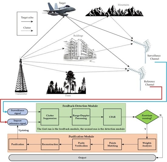
Figure 1 illustrates a representative detection scenario in the PBR system, considering the presence of the impure reference signal. The received signal within the surveillance channel adheres to the conventional assumptions of the PBR system, encompassing components such as direct path or multipath clutter, target echo, and noise signal. In contrast to the traditional reference signal, the reference channel in the newly proposed signal model not only comprises the direct path clutter, a limited amount of multipath clutter, and noise signal, but it also incorporates the reception of target echo signals. The presence of moving echo signals within the reference channel induces unexpected Doppler frequency shifts, posing several challenges to the conventional target detection methods employed in PBR systems.
Following the process of analog-to-digital sampling and subsequent digital down-conversion, the ideal reference signal is characterized by the following model:
with
where
Sref [
l] denotes the
nth sampling datum received by the reference channel,
d[
l] represents the
lth sampling data of the direct path signal,
is the corresponding complex amplitude, the received noise signal is represented by
, and
L is the data length. When a target appears in the airspace in the direction the reference channel is pointed at, the reference signal represented by (1) can be rewritten as:
where
,
, and
denote the complex amplitude, range unit respecting to direct path signal, and Doppler frequency shift of the
nth target echo in the reference signal, respectively. Moreover,
is the baseband signal sampling rate, and
NT represents the number of targets in the reference signal.
Similarly, the surveillance signal received by the surveillance channel can be represented as:
where
and
are the complex amplitude and range cell of the direct path or multipath clutter in the surveillance signal, respectively;
NC is the number of clutters;
,
, and
denote the complex amplitude, range unit, and Doppler frequency shift of the
mth target echo in the surveillance signal, respectively;
NM is the target number; and
is the echo noise.
Generally, the target echo received by the reference channel can also be simultaneously detected by the surveillance channel, that is,
NM ≥
NT. For the sake of analytical convenience and without sacrificing generality, let
NT = 2 and
NT = 1, so the reference signal and echo signal represented by (3) and (4), respectively, can be further updated as:
2.2. Analysis of the Influence of Signal Model on Target Detection
In this subsection, the impact of the new signal model on the PBR target detection is analyzed from two aspects:
(1) Influence on Clutter Suppression: In the PBR, the extensive cancellation algorithm (ECA) [
27,
28] is a widely used algorithm for clutter suppression. The fundamental concept behind the ECA is to reduce clutter by projecting the surveillance signal onto the orthogonal subspace created by the reference signal and its time-delayed cells, and its projection coefficients vector is given by:
where (•)
H represents the Hermitian transpose operation and
V denotes the orthogonal subspace created by the reference signal
Sref and its time-delayed cells. Furthermore, the key expression of the ECA can be given as:
where
Serr and
W denote the residual signal and the corresponding projection matrix of the ECA, respectively. In addition,
K represents the maximum time-delayed cells of the reference signal. Substituting (5) and (6) into the above formula, (8) is further expressed as:
where
where
,
,
, and
denote residual clutter, the echo around target 1, the echo around target 2, and the noise, respectively. For comparison, in the same way, substituting (1) and (6) into (8) produces:
where
,
, and
are the same as the three terms in (9), and the only difference between (9) and (14) is
, which is given by:
From (11) and (15), when the reference signal is impure, it can be inferred that in the presence of an impure reference signal, the target echo within the surveillance signal after the ECA will inevitably be influenced by the same target signal received by the reference channel. The potential impact on target detection can be categorized as follows: firstly, the amplitude of the real target will experience attenuation, thereby reducing the signal-to-noise ratio (SNR) associated with the target. Then, some false targets attached to the real target may appear.
(2) Influence on the Cross-Ambiguity Function (CAF): Followed by the RDCC, in the PBR, the SNR of target detection is improved by utilizing the RDCC based on CAF [
29], which is defined as:
where (•)* means the conjugate operation,
denotes the range cell of the target of interest, and
is the corresponding Doppler cell. Substituting (5) and (9) into (16) yields:
where
where
,
, and
represent the matching results of the residual clutter with the direct path clutter, target echo, and noise in the reference signal, respectively.
,
, and
denote the matching results of the target existing in both the surveillance channel and reference channel, respectively.
,
, and
are the matching results of the false targets, respectively.
,
, and
are the matching results of the target only received by the surveillance channel, respectively.
refers to the matching results of the noise.
After the ECA, theoretically, the residual clutter will not affect the CAF of the target. In addition, due to the random nature of noise, the CAF of the noise does not matter. Furthermore, although the target signal in residual surveillance signal and the one in the reference signal can be matched, the energy intensity is negligible. Therefore, the matching results involved in these cases will be ignored in the following analysis, and (17) is further simplified as:
Following a similar derivation, substituting (5) and (14) into (16) produces:
Comparing (31) and (32), it can be found that the amplitude of target T1 in (31) is lower than that of target T1 in (32); that is, the impure reference signal will negatively benefit the detection of the target received by both the surveillance channel and reference channel. On the other hand, compared to (32), (31) has one more matching term, which has the same Doppler shift as target T1, but the range cells demonstrate a pseudo-random distribution related to the clutter suppression coefficients, thereby interfering with the normal detection of target T1.
3. Proposed Target Detection Method under the Condition of Impure Reference Signal
To overcome the negative impact of the impure reference signal on target detection, a novel target detection method based on fusion feedback and reference signal purification is proposed. The detailed process is introduced as follows.
3.1. Localization of Impure Terms in the Reference Signal
As discussed in the previous section, when the reference signal is perturbed by target echoes, resulting in signal impurity, the presence of false targets originating from real targets becomes apparent. These false targets share the same Doppler shifts as their corresponding real targets, while their range cells exhibit a pseudo-random distribution influenced by clutter suppression coefficients. That is to say, in this case, there will be several sparsely distributed points exceeding the detection threshold in a certain Doppler channel of the Range–Doppler detection plane. These points comprise a mixture of real and false targets, presenting challenges for direct identification. However, exploiting the relative positions of these points, which are associated with clutter suppression weights, enables the distinction and localization of real and false targets. To illustrate this concept, we consider a scenario where the direct path and multipath clutters in the surveillance signal occur on the 1st, 8th, and 19th range cells. Consequently, during the projection process of clutter suppression, the projection coefficients will have peaks on the 1st, 8th, and 19th cells, while the remaining range cells demonstrate negligible projection coefficients due to the absence of significant clutter. By building upon this quantitative analysis, (9) can be further expanded as:
From (33), it is not difficult to deduce that four targets will be generated after the RDCC, among which and are real targets, while and are false. Moreover, the range cells of the two false targets are located at and , respectively. That is, the relative distances between the real target and the two false targets are 7 and 18 range cells, respectively. Therefore, the positions where the false targets appear are related to the peak values of the projection weight coefficients of the clutter suppression. Employing the prior information, the impure terms in the reference signal introduced by the target echo can be located.
3.2. Reference Signal Purification Method
Based on the method proposed in the previous subsection, the identification of the impure component within the reference signal can be achieved. The subsequent focus of this subsection revolves around the reconstruction of the signal and the subsequent purification of the reference signal through subtraction from the original reference signal. This purification process aims to mitigate the adverse impact of impurities on target detection.
Comparing (9) and (14), it can be seen that the only difference between the two formulas is
in (9). For analysis, here,
is rewritten as:
Due to the fact that a target is received by both the reference channel and the surveillance channel, the two channels should be very close to each other. As a result, it can be considered that the energy of the target received by the two channels is approximately equal, i.e.,
. In the practical scenarios of the PBR, in order to achieve full coverage of the airspace, multiple digital wave beams are generally employed for target detection. Among them, one wave beam serves as the reference channel, used to receive the reference signal, while the rest are surveillance channels, used to detect signals from the targets of interest. These digital wave beams overlap and cover each other. Therefore, this approximation is reasonable for the surveillance channels adjacent to the reference channel, but it does not hold true for other surveillance channels that are far away from the reference channel. Based on this approximation, (34) is further expressed as:
where
is the real target term after clutter suppression, while
is the original term of this target, and the other term is the set of false targets originated from the real target. When the target in the reference signal is eliminated, the false targets will also disappear. In other words, if
can be reconstructed, and then the impure reference signal with the existence of
can be purified. Although it is almost impossible to reconstruct
directly, it can be reconstructed indirectly from
.
Among
,
and
can be obtained by the proposed localization method, while
is known. Therefore, as long as
is estimated,
can be reconstructed. To achieve this purpose, inspired by the ECA,
in
can be estimated by utilizing the subspace projection method similar to the ECA. Given
and
, the subspace of the estimated impure term constructed by the impure reference signal is represented as:
Replacing
Ssur with
Serr, the weights of the ECA can be updated as:
Equation (37) indicates that the residual signal
Serr after clutter suppression is projected onto the subspace
of the estimated impure term in the reference signal to obtain the energy projection coefficients
of the signal, which matches the impure term in
Serr. Therefore, based on
, the impure term in
Ssur can be estimated as:
After rearranging, (38) is given by:
The left term of (39) is equal to the impure term introduced by the reference signal in (5), and the right one is the corresponding reconstruction term. Obviously, by subtracting (39) from (5), the purified reference signal can be obtained, which is expressed as:
From (40), it is easy to see that the purified reference signal and (1) are almost equivalent. Treating (40) as the reference signal for target detection, theoretically normal detection results can be obtained.
3.3. Target Detection Method Based on Impure Reference Signal
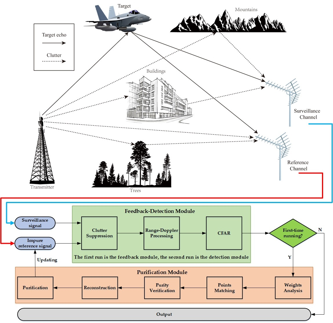
Combined with the localization and reconstruction methods proposed above, the flowchart of the target detection method under the condition of an impure reference signal is shown in
Figure 2, while the detailed steps of the proposed method are summarized in Algorithm 1.
| Algorithm 1 The core steps of the target detection method under the condition of impure reference signal. |
| 1 | Input: Original reference signal Sref, surveillance signal Ssur. |
| 2 | Initialization: and other related parameters. |
| 3 | Clutter suppression: Apply ECA on Sref and Ssur to obtain the residual signal Serr and weight coefficients W. |
| 4 | RDCC:. |
| 5 | Points detection: Go through each p channel in [1, F] with interval 1 to achieve all the points exceeding the detection threshold.
For p = 1, 2, …, F do
Each cell is detected in turn as follows:
end |
| 6 | Weights analysis: Sort the weight coefficients of W, and save the corresponding range cells l1 and l2 of the two coefficients with the largest values. |
| 7 | Points matching, go through each p channel in [1, F] with interval 1 to distinguish between real and false targets, while saving real targets information, which is performed as
For p = 1, 2, …, F do
Pairwise matching is conducted for range cells with a value of one within the channel as follows
.
end |
| 8 | Purity verification:, go through each p channel in [1, F] with interval 1 to determine whether the reference signal is pure.
For p = 1, 2, …, F do
, record the corresponding range cell r and Doppler cell p, and pass them to next step; otherwise, enter the next loop.
end |
| 9 | Reconstruction: Based on the saved r and p, the target signal in the reference signal is reconstructed via (20). |
| 10 | Purification: The reference signal is purified via (21). |
| 11 | Target detection: Based on the purified reference signal and surveillance signal, go back to step 3, 4, and 5 to obtain the updated . |
| 12 | Output: Save the detection result matrix and then output it for subsequent signal processing. |
4. Simulations and Analysis
In this section, the effectiveness of the proposed method is validated and analyzed by using both it and a traditional method to process the simulated data. In the experiments, the FM signal is utilized as the transmitting signal of the PBR. The key system parameters used for simulated data are listed in
Table 1 and the detailed parameters of the reference signal and surveillance signal are described in
Table 2 and
Table 3, respectively. From
Table 2 and
Table 3, it can be seen that the only difference between the pure case and the impure case is whether the surveillance signal is included in the reference signal. Next, the proposed target detection method and conclusions of the theoretical analysis are verified from two aspects.
(1) Validation of the impact of impure reference signals on target detection performance: In this subsection, the traditional target detection method is employed for target detection in the pure case and the impure case. First, the ECA is used to suppress clutter in both cases, and the difference between them in clutter suppression is evaluated using the clutter suppression factor (CSF), which is defined as:
where
y stands for the CSF, and the bigger, the better. The values of the CSF for those two target methods are shown in
Figure 3. From
Figure 3, it can be observed that, regardless of whether the reference signal is pure or not, the values of the CSFs of the two methods are almost equivalent, and the value of the proposed method is slightly higher. The main reason for this difference is the additional target term in (9). On the other hand, it is further shown that in the surveillance signal, the energy of the targets is almost negligible compared to that of the clutter. Then, the RDCC processing results of the traditional target detection method in the pure case and the impure case are given in
Figure 4a,b, respectively. As is apparent, more suspected real targets can be observed clearly in
Figure 4b and the energy of the real target, whose range cell is 73, is also weakened, thus verifying the negative benefit of the impure reference signals on target detection. Furthermore, the unit average detection method is applied to detect the targets, and the detection results are shown in
Figure 5a,b. By comparison, it is not difficult to see that more false targets will be detected in the impure case, among which, in addition to real targets, some of them are random false targets, and the rest are false targets derived from the real target. There is no doubt that the existence of more false targets will bring more interference to the localization and tracking of real targets.
(2) Effectiveness of the proposed target detection method: In this subsection, based on the impure reference signal and the surveillance signal, the proposed method and the traditional method are utilized to detect the three targets in the surveillance signal, respectively. Firstly, the ECA is performed to obtain the weights of the clutter suppression of the two methods, and the amplitudes of the weights of the proposed method are presented in detail in
Table 4. As is shown, within the range cells where the clutter actually appears, such as in cells 1, 10, and 25, the corresponding weight values will have obvious peaks, while those corresponding to the other range cells are very small, which is consistent with the previous analysis. The core reason for this phenomenon is that clutter plays a major role due to the orthogonality between targets and the reference signal subspace. Then, the detection results of the two methods for target 1 and target 2 are depicted in
Figure 6 and
Figure 7, respectively. By comparison, it can be found that exploiting the proposed method for target detection can effectively overcome the problems of weakening target energy and generating false targets occurring in the conventional detection method. Next, the detection results of target 3 using the two methods are given in
Figure 8. Clearly, target 3 existed only in the surveillance signal and is insensitive to whether the reference signal is disturbed by other targets or not; at the same time, the proposed method will not have any negative impact on the detection of target 3. Moreover,
Figure 9 shows an overall comparison of the detection results obtained by using the proposed method and the traditional method to process the impure reference signal. It is easy to observe that the proposed method effectively purifies the reference signal and achieves cleaner target detection results. Finally, based on Matlab2020b and Intel i5 CPU processors, the execution efficiency of the two methods is compared in
Figure 10. It can be seen that the execution efficiency of the proposed method is lower than that of the traditional method. The main reason for this problem is that the proposed method regards the detection results of the traditional method as feedback information, and on this basis, signal recognition and reconstruction are added successively, thus reducing the computational efficiency. Furthermore, according to the flowchart of the proposed method in
Figure 2, the proposed method is divided into three modules: one is the feedback module, another is the detection module, and the last one is the reference signal purification module.
Table 5 provides the running time and proportion of time each module takes up in the proposed method. It is evident that the main computational cost of the proposed method lies in the feedback and detection modules. These two modules process different data, but the methods are the same, allowing them to be accelerated through parallel computing.
Although the foregoing contents demonstrate the effectiveness of the proposed method in dealing with the problem of the impure reference signal, it is undeniable that the proposed method still has certain limitations. Firstly, for multiple targets with the same velocity, such as grouped targets, the tracks of these targets may fall into the same Doppler cell, causing interference in distinguishing real and false targets, thereby rendering the proposed method ineffective. Secondly, the proposed method is not applicable in cases where the surveillance channel is far from the reference channel––for example, when the surveillance channel and the reference channel are deployed back-to-back. The overlap of the main lobe of the surveillance channel and the reference channel is a fundamental condition for applying the proposed method. Lastly, although the proposed method can theoretically handle any targets with different Doppler frequencies in the reference signal, in practice, there is a trade-off between performance and efficiency.
5. Conclusions
In this paper, a comprehensive investigation was conducted to analyze the implications of target-echo-induced disturbances within the reference signal on conventional target detection methods. Subsequently, a pioneering approach for addressing this scenario was introduced. Specifically, leveraging the distinctive attributes of impure reference signals, a novel signal model was devised, followed by a detailed examination of its impact on the principal components of target detection. Drawing upon the valuable information embedded within the reference signal, a novel target detection method was proposed that incorporates a two-step process involving signal localization and subsequent signal reconstruction. In comparison to traditional methods, the proposed approach effectively mitigates the adverse effects of impure reference signals on target detection, thereby enhancing the integrated gain of the RDCC for specific real targets while minimizing the occurrence of false targets. Extensive simulation results have corroborated the superiority of the proposed method. However, although the proposed method has achieved some satisfying results, there are still some remaining issues that deserve to be studied in the future. For example, the current implementation of the proposed method exhibits relatively low computational efficiency, which may impede its practical application. Enhancing the execution efficiency of the proposed method through the integration of parallel processors is an ongoing effort. In addition, how to deal with the problem of impure reference signals when the main lobe of the reference channel and the surveillance channel do not overlap is another valuable research topic.


