1. Introduction
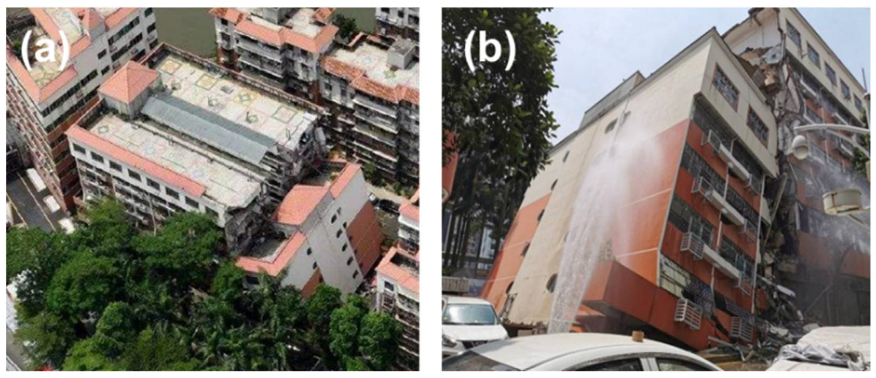
In recent years, the urbanization processes of emerging super-large agglomerations have accelerated rapidly, and the disturbance caused by human activities to the environment has been increasing. In subway and large-diameter shield tunneling projects, underground space is constantly being developed to create the spatial layout required in regional development. Among the world’s 25 most advanced large-diameter shield machines, 18 are in China, and 6 are in Shenzhen. In 2020, more than 200 shield machines were being used to carry out underground projects in Shenzhen. Large-scale underground construction brings about potential threats to aging buildings. In Shenzhen, the total number of historical illegally built buildings exceeds 50%, and 7.38 million residents live in 1836 urban villages in the city. Most buildings in urban villages are aging, and densely built areas can easily be affected by multiple risks, such as subway construction, concealed culverts, and geo-hazards. In August 2019, a settlement and inclination incident occurred in a seven-story aging building in Hepingxinju, Shenzhen, due to underground construction. When the accident happened, the eastern side of the building inclined into the western structure (as shown in
Figure 1). Personnel in the building were evacuated in advance, and fortunately, no casualties were caused. In this situation, establishing a monitoring and evaluation method for post-tunneling building damage is particularly important to ensure the safety of people’s lives and properties.
Traditional monitoring techniques for buildings and infrastructure are generally divided into manual inspection and in situ monitoring techniques. While the accuracy of both means is reliable, only a small number of structures can be monitored consistently in the long-term. Nowadays, with the development of Earth observation technologies, satellite remote sensing can be used in conjunction with traditional monitoring techniques to provide multi-scale information about buildings and infrastructures.
Interferometric Synthetic Aperture Radar (InSAR) measures relative surface displacement within the sensor’s LOS (line of sight), whose imagery is not affected by daylight or cloud cover [
1,
2]. Thus, InSAR has attracted attention from scholars in the field of Earth sciences for a long time [
3,
4,
5]. To solve several problems that limit the accuracy and reliability of traditional differential InSAR, time-series InSAR has been developed and popularized [
6,
7]. The algorithms mainly fall into two main categories: one is persistent scatterer InSAR (PSI), with a single image as the primary image [
8,
9,
10]; the other is small baseline subsets (SBAS), with multiple images as the primary image [
11,
12]. Other algorithms developed on the basis of PSI are IPTA [
13], PSP [
14], etc. In addition to SBAS, TCP-InSAR [
15], PSIG [
16], etc., have been developed on the basis of small baselines. StaMPS [
17] exists, which is a hybrid approach incorporating PSI and SBAS. These algorithms have been effectively used in traditional subsidence and deformation monitoring application scenarios, such as volcanic activity [
18], earthquake and faulting activity [
19], landslide instability [
20], groundwater and mining exploitation [
21], and urban land subsidence [
22]. With the increase in image resolution, these methods are gradually being applied to research into buildings and infrastructure, including railways and highways [
23,
24], buildings [
25,
26], bridges [
26,
27], and transportation hubs [
28,
29]. Despite the wide range of applications, the interpretations and analyses based on existing time-series InSAR techniques still separate themselves from directly indicating the risk conditions of buildings and infrastructure, which obstruct time-series InSAR techniques from having effective operational applications.
In this study, we addressed the above problems by developing a subsequent analysis method of time-series InSAR. First, a Nonuniform Settlement Index was developed by generating a 3D settlement plane and calculating the inclination angle on the basis of time-series InSAR processing. Next, we tested the performance of the proposed Nonuniform Settlement Index using an inclined aging building (Hepingxinju), whose safety condition had been disturbed by tunneling works. The deformation conditions of the overall surface along the tunnel and the test buildings were revealed using COSMO-SkyMed acquisitions. Finally, the inclination and settlement trend revealed using the InSAR Nonuniform Settlement Index are cross-compared with in situ investigations in other aging buildings, which verifies the efficiency of the proposed methodology.
2. Methodology
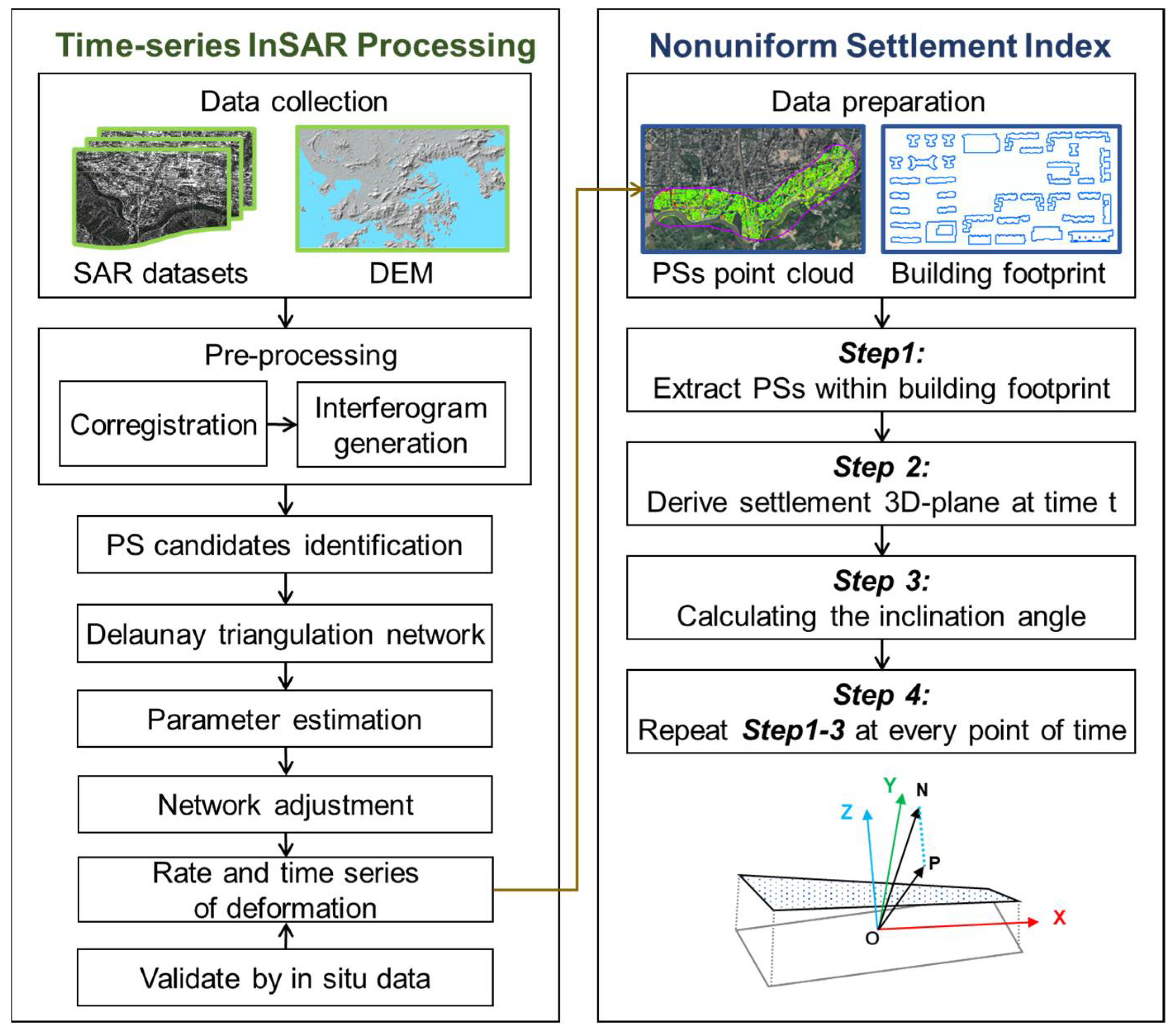
Time-series InSAR has been applied not only to the large-scale geological processes, but also to the refined monitoring of a single building or structure by inversing the general parameters of persistent scatterers (PSs), such as deformation rate and time series. Nevertheless, it is impossible to determine the safety condition of buildings and infrastructures by relying solely on these parameters. We developed the Nonuniform Settlement Index (NSI) as an evaluation method of time-series InSAR. First, PSInSAR is used to process high-resolution SAR images to determine spatio-temporal trends in the test area. The monitoring result is cross-validated by static level. Then, NSI is introduced to calculate the 3D settlement plane and inclination angle with InSAR-derived spatio-temporal information of the test buildings. The workflow of the proposed methodology is given in
Figure 2.
2.1. Time-Series InSAR Monitoring
2.1.1. Time-Series InSAR Processing
In this study, we employed an improved time-series InSAR algorithm [
29] to extract the PSs of the study area. Using a stack of M + 1 SAR images, M interferograms were generated by master–slave pairs. Then, the interferometric pairs were used as the input of the detecting workflow for PS target detection. First, the amplitude dispersion index (ADI) [
8,
9] and averaging coherence coefficient were jointly adopted to select PS candidates. Second, the Delaunay triangulation network was formed, consisting of arcs with PS candidates on the endpoints. Third, values of velocity and height were calculated through the comprehensive use of beamforming and M-estimator, to robustly estimate the parameters of the PSs [
25]. To further determine the density of the measuring points, adaptive densification and omnidirectional expansion were applied to densify the PSs [
30]. Finally, the derived deformation rate along the satellite line of sight was projected to the vertical direction to characterize the uneven situation of the buildings.
2.1.2. Validation
A static level is a fine instrument for measuring subsidence; it is commonly used in Structural Health Monitoring. It obtains the relative subsidence between the measuring points by recording the change in liquid level in connected pipes. In our study, the processing results of time-series InSAR were validated by static level. The measuring points by static level were installed on the corners of the building roofs. Two issues should be stressed by cross-comparing data from these two measuring systems.
The first issue is spatio-temporal alignment. Since InSAR monitors a longer period with a lower temporal sampling frequency compared with the static level, accuracy evaluations are carried out within the sensing period of static level, and each time point is basically based on time-series InSAR. For the geolocation inconsistency of the static level points and PSs, clusters of PSs around static level points are processed by Kriging interpolation so that the geolocation of the representatives of the PSs is consistent with static level points.
The other one is the inconsistency of the physical significance of the measured parameters. Time-series InSAR calculates the deformation rate relative to the reference point (with a deformation rate of 0 mm/year), which is often selected on a stable target in the centered position of the SAR image. A static level measures the subsidence of the roof corners by choosing one corner as the reference. Supposing A–B–C–D are the corners of a tested building, and A is the reference point of static level, then the deformation of corner B–C–D by static level can be written as:
The measurement by InSAR is
Then, the transferring can be given as:
Additionally, the error of time-series InSAR can be expressed as:
However, due to specific side-looking angle, the results of time-series InSAR may exhibit a lack of PSs around the reference point of static level. Therefore, double difference should be made by transferring the benchmark of the two techniques. Assuming there is a lack of PSs around corner A, and the benchmark for comparison is transferred to corner B, double difference can be made as:
In this case, the error of time-series InSAR can be expressed as:
The accuracy analysis is evaluated by two indexes, mean error and root mean square error, which are formulated by:
where
is the mean error,
m is the root mean square error, and
is the number of the time points. To this end, the validated PSs are generated as an input of index analysis to further analyze the safety conditions of the buildings.
2.2. Nonuniform Settlement Index (NSI)
2.2.1. Problem Description
On the basis of the time-series InSAR processing described above, in the SAR monitoring area, a point cloud dataset consisting of N + 1 PSs is obtained, which is denoted as:
where
represent the three-dimensional coordinates of PSs, respectively, and the observed deformation variable of the point at time t is denoted as
. At the same time, the vector footprint layer of the buildings in the SAR monitoring area is georeferenced in the same coordinate system as the PSs. The problem that needs to be solved is to utilize the available PSs point cloud and the building footprint vector data to classify the ground buildings into two types of building risk categories: risky or non-risky.
2.2.2. Algorithm Description
Aiming at the problems raised above, this paper proposes the use of Nonuniform Settlement Index (NSI) to identify building risk categories. The calculation of the designed index is as follows.
Step 1: In order to characterize the settlement information of a single building, it is necessary to segment the input PSs point cloud according to the geographical coordinates of each individual building provided by the building footprint vector data. To this end, we define the spatial relationship between each single building footprint vector and each PS as follows. A PS is inside, outside, or at the edge of the single building footprint, and one of the three must be chosen. Based on this spatial relationship, a subset of point clouds inside the corresponding building vector box, j, can be extracted by further screening the height of the PSs compared with surrounding PSs on the ground, denoted as .
Step 2: The next step is to use the extracted point cloud subset to find the settlement plane of the single building at time t. To this end, the z component representing the elevation information in the coordinates of each point in the point cloud is replaced by the component representing the settlement information. Using the modified point cloud data, a parametric 3D plane can be estimated based on the least-square principle, which is formulated as follows:
where
are the fitting parameters of the plane.
Step 3: The 3D fitting plane obtained in step 2 can already represent the inclination degree of the corresponding single building at time
, but it is still not convenient to directly compare the plane parameters obtained at different times to represent the change information of the single building inclination over time. Therefore, the tangent value of the plane inclination angle is calculated through the plane equation parameters, which reflects the inclination degree of the single building at time t with respect to the horizontal direction:
Step 4: Repeat steps 1 to 3 for each different time to obtain the entire time series of the plane inclination of a single building, followed by calculation of the acceleration rate of the index in order to more intuitively observe the rate of change in the plane inclination over time.
Notably, the precision of the evaluated result in the previous introduced algorithm highly relies on the precision of the sample points used and their spatial distribution; we cannot guarantee that the settings are always optimal. In this way, we modified the traditional least-square principle to improve the estimation accuracy in two ways. First, we estimated the parameters repeatedly rather than only once. In each iteration step, the Huber loss function [
31] is used to evaluate the residual of sample data and assign the weight factor accordingly for the next iteration. In this way, the influence of most singular samples is mitigated. Second, the calculation of the matrix inverse is conducted via singular value decomposition (SVD) to handle the numerical issues. Mathematically, a symmetric matrix can be decomposed by SVD as follows:
where
are the singular values of matrix P, and the columns of orthogonal matrices U and V are formed by the left- and right-singular vectors of P. Thus, the matrix inverse via SVD has following form:
We analyzed the singular values and compared their values to determine whether the rank of the design matrix was not full. In this situation, the ratio between the smallest and the largest singular values is near zero, and an empirical threshold (ratio = 0.1) is used to identify this situation. If this is the case, we set the reciprocal of the smallest singular value to zero during the calculation of inverse matrix. In this way, we imposed a rank constraint to the calculation of matrix inverse and mitigated numeric inaccuracies.
Through NSI calculation, when the acceleration rate was greater than a preset threshold, it was determined that the corresponding single building belonged to the risky category; otherwise, it was determined to be the non-risk category. In practice, the threshold should be determined based on trial calculations of a multitude of deformed and inclined samples of buildings, which is not easy to require due to limited samples. In preliminary practice, the risky conditions can be considered by comparison with buildings in assured safety status.
3. Test Site and Data
3.1. Test Site
3.1.1. The Aging Buildings
Nine aging buildings, including the inclined Hepingxinju located in the Luohu District of Shenzhen, were chosen as our test sites.
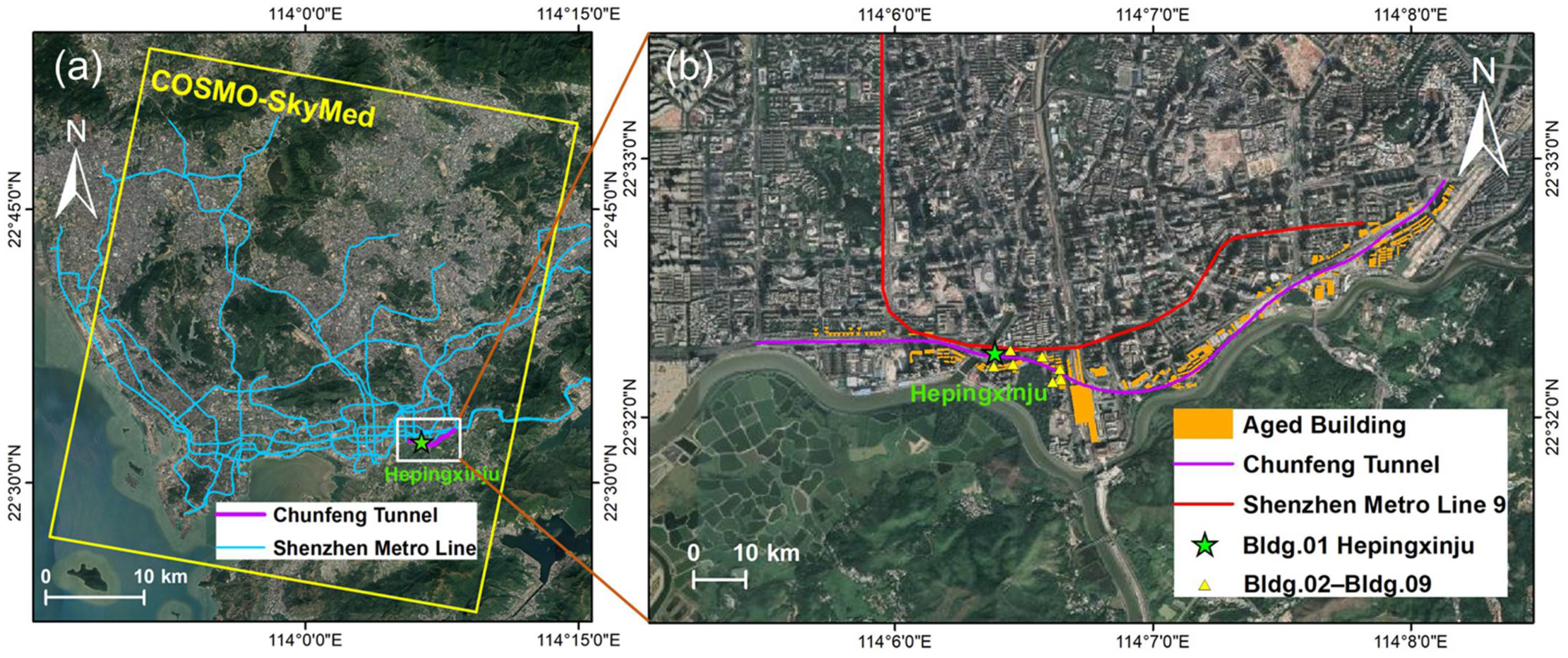
Figure 3 illustrates the spatial distribution of the tested buildings, and
Table 1 gives the basic information of the sites. The surrounding environment of the buildings belongs to the early development and construction area in Shenzhen. In this old urban area, aging buildings with a service time of more than 20 years are widely distributed; these structures are prone to external disturbances, especially large-diameter-tunneling-induced deformation. As shown in
Figure 3b, the purple line denotes the centerline of Chunfeng Tunnel, which was the largest diameter shield tunnel when its construction started in 2019.
3.1.2. Hepingxinju
Hepingxinju (Bldg.01 of the tested buildings) was constructed in June 1989 and was completed in January 1990; it has been in service for more than 30 years. It is about 50 m long from east to west, and 20 m wide from north to south. The underground foundations of the building are built on a trunk canal, which is the main drainage channel in the low-lying areas of the central urban area of Luohu District. Referring to the geology condition, there is a thick mud layer under the building, and the sand layer is unevenly distributed beneath the mud layer. The settlement and inclination incident of Hepingxinju occurred on 28 August 2019. After that, an investigation of the incident was gradually carried out.
3.1.3. Tunneling Works
There are two tunneling projects located around Hepingxinju, which potentially threaten to the safety condition of the building at various periods.
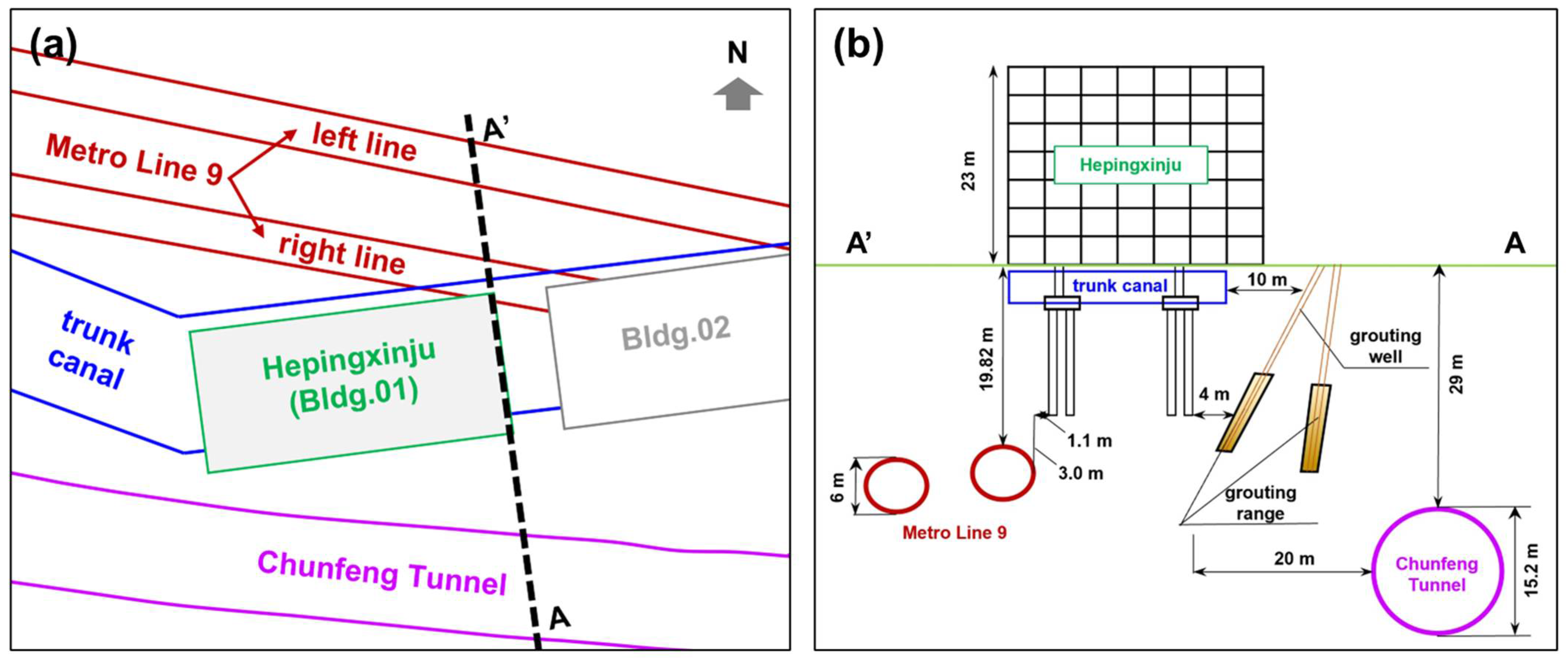
One of these is the Shenzhen Metro Line 9. It passes through Hepingxinju in the Luren section, on which construction started in 2014 and finished at the end of 2016. The right line of the tunnel in the Luren section runs through the northeast corner of the building. The horizontal distance between the tunnel vault and the bottom of the immersed pipe pile of Hepingxinju is 1.1 m, and the vertical distance is 3.0 m, as shown in
Figure 4b.
The other one is Chunfeng Tunnel. This passes through the old urban area, with complex engineering geological conditions. The urban area locating above Chunfeng Tunnel is shown by the optical image in
Figure 3b, where the purple solid line is the central line of the tunnel, and the orange polygons are 150 aging buildings located in the 100 m buffer zone along the tunnel central line. These aging buildings have been in service for over 20 years. The foundation forms are mostly natural foundation and small-diameter friction piles, and the above-ground structures are masonry and bottom frames, which have weak resistance to nonuniform deformation. On the corresponding ground surface, public facilities are densely covered, including the Shangbu overpass and Luohu Railway Station. Chunfeng Tunnel passes through this area from the southern side of Hepingxinju (shown in
Figure 4a). The horizontal and vertical distances between the tunnel and the building are about 20 m and 29 m, respectively, as shown in
Figure 4b.
3.2. Data
3.2.1. SAR Data
In total, 147 scenes of COSMO-SkyMed images obtained from 2013 to 2022 were used in our study. The whole dataset was processed by three groups by dividing from November 2016 and August 2019, since single processing can hardly preserve high coherence during nine years. These three groups were all acquired in descending orbit with 3 × 3 spatial resolution and HH polarization. The satellite observes the test site with a frequency of two times per month on average. The coverage of the COSMO-SkyMed acquisition is shown by the yellow polygon in
Figure 3a, which covers most of the central and western parts of Shenzhen. The basic information of the three SAR datasets is given in
Table 2.
3.2.2. In Situ Observations
To validate the reliability of time-series InSAR processing, data collected by in situ static level were employed for cross-comparison with satellite-derived subsidence. In our study, 34 static level points installed on five buildings were collected.
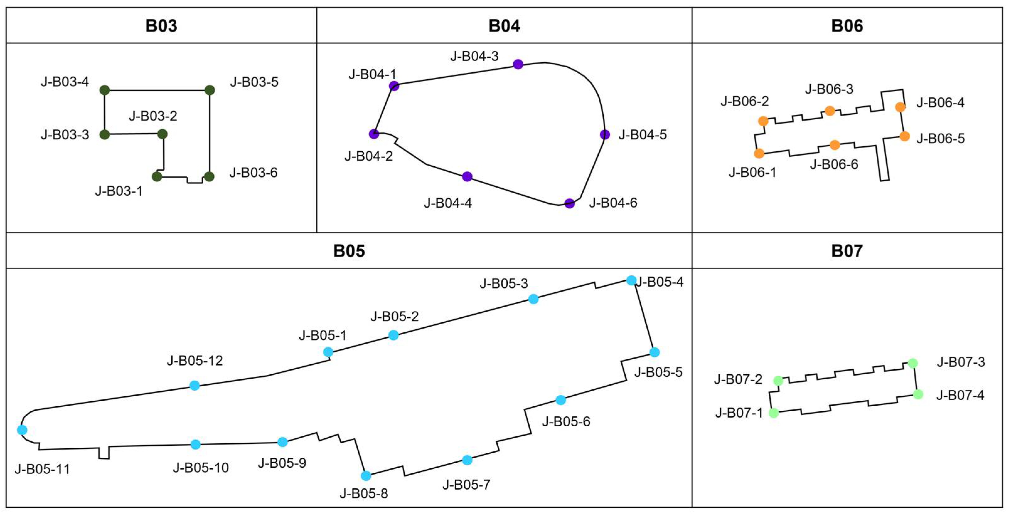
Table 3 shows the number of points;
Figure 5 gives the static level layout of each building. Generally, the No.1 point on each building is the reference of the static level. The static level points were installed on other adjacent aging buildings along Chunfeng Tunnel after the inclination incident of Hepingxinju; data were collected after September 2020, and could only be prepared with SAR dataset III. To verify the proposed NSI, grades by manual inspection of each building were employed here; these were collected by carrying out in situ investigations in 2017, following the local standard [
32]. In addition, this study used the footprint vector data of the aging buildings along the tunnel to extract PSs clusters belonging to each building (see the orange polygon proposed in
Figure 3b).
4. Results and Analysis
4.1. Monitoring Result
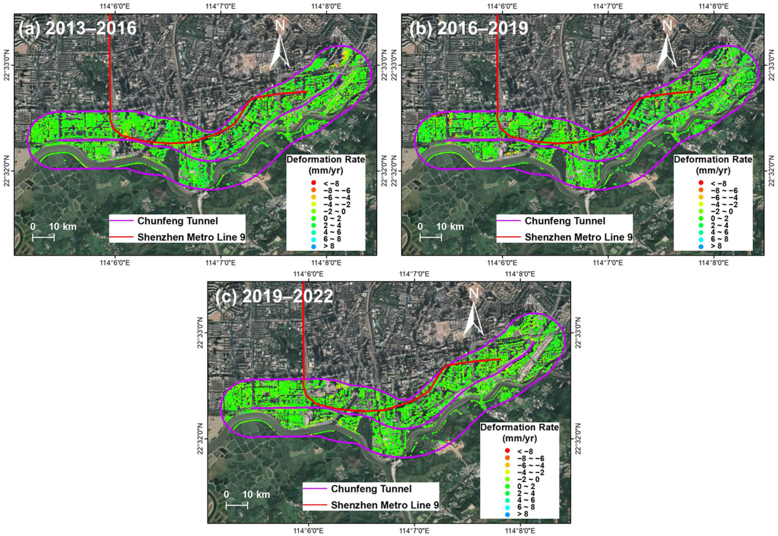
The vertical deformation rates derived by time-series InSAR from COSMO-SkyMed datasets are given in
Figure 6. PSs within the 500 m buffer zone of Chunfeng Tunnel have been retained, where the red points represent a subsidence rate of less than −8 mm/year; the blue points represent an uplift rate of larger than 8 mm/year; and the green points represent the deformation rate ranging from −4 mm/year to 4 mm/year, which can be considered stable on the surface. In the period of 2013 to 2016, a stable pattern with deformation rate ranging from −10.98 mm/year to 9.78 mm/year was recognized along the centerline of the tunnel. From 2016 to 2019, an uneven deformation pattern was exhibited by PSs ranging from −15.91 mm/year to 12.20 mm/year. Subsidence mainly occurred to the western side when the cut-and-cover section was constructed here. During the third period, the overall pattern stabilized, with the deformation rate ranging from −11.40 mm/year to 9.34 mm/year.
The time-series InSAR monitoring results were cross-validated by static level data in the five tested buildings. The sensing period of the static level was from October 2020 to September 2021; therefore, validation was conducted on the PSs generated from dataset III. As described in
Section 2.1.2, due to the side view of SAR, PSs could only be generated on specific sides of the building; only part of the points of static level can be taken advantage of. By double difference illustrated in
Section 2.1.2, spatio-temporal aligned results from two techniques are generated and compared in ten locations, as listed in
Table 4. The mean error and root mean square error of the measured results were ±1.97 mm and ±2.2 mm, respectively. The evaluation results indicate that time-series InSAR monitoring shows preferable consistence with in situ measurement.
Focusing on Hepingxinju,
Figure 7a,c display the PSs generated that belong to the polygon vectors of Hepingxinju as well as its adjacent building. Although the aging Hepingxinju building finally inclined, precursor information cannot be obtained by only determining from the deformation velocity. The deformation rate varied from −4.39 mm/year to 3.14 mm/year during 2013 to 2016, and from −0.74 mm/year to 3.24 mm/year during 2016 to 2019, neither of which denoted significant risky conditions of the two buildings.
4.2. Risk Analysis of Bldg.01–02
4.2.1. NSI Analysis
Hepingxinju and its adjacent building, which are marked as Bldg.01 and Bldg.02, respectively, were first analyzed and compared using InSAR NSI. Since Bldg.01 had been inclined and damaged in August 2019, its adjacent Bldg.02, which shared very similar above-ground and underground environment, was kept unoccupied and until finally being demolished in 2020, even though no obvious uneven subsidence occurred. Therefore, no PSs belonging to these two buildings were generated from the processing of dataset III. Additionally, the NSI developed in 2.2 could be calculated from 2013 to August 2019 for these two buildings.
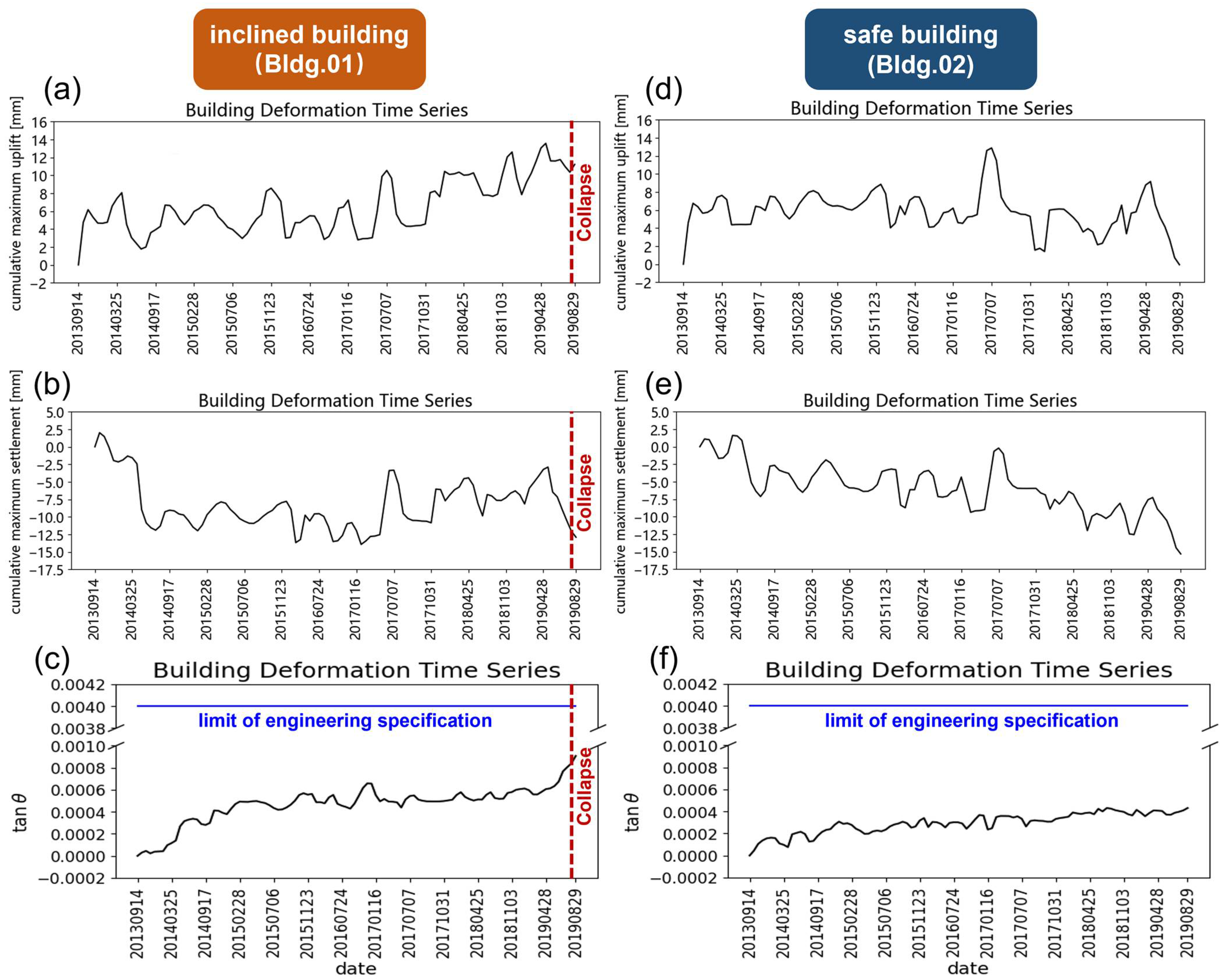
Figure 8 presents the calculation results, showing the time-series curves of the PS point clouds of the two buildings.
Figure 8a–c were derived from the settlement data of the inclined building Hepingxinju, and
Figure 8d–f show the comparison curves calculated from the normal building settlement data in the same period. The curves were calculated at each time point using screened PSs. Compared with existing analysis methods of selecting single or multiple points as representatives, calculation results from the whole point clouds indicating the settlement plane and the inclination angle may better reflect the objective conditions of the buildings.
By comparison, it is easy to notice that the curves of the cumulative maximum uplift and settlement in the first and second rows have larger fluctuations and higher frequencies than the curves in the third row, whereas the nonuniform settlement curves in the third row are more stable in numerical values. Comparing the overall trends in the left and right columns, the curves of the normal building on the right show a certain degree of global linear trend in the three indices, while the three indices of the inclined building on the left stabilize in the middle part and start climbing at the end of the curves. The acceleration rate of the first line on the left is significantly weaker compared with the upward trend of the third line on the left at the end of the curve.
4.2.2. Trend Analysis
In order to further compare the differences in each settlement index between inclined buildings and normal buildings and exclude the influence of random noise in the indices on the building risk distinguishment, this study used the open-source third-party function library PolyTrend to perform trend analysis and remove the noise of the time series signal. PolyTrend has been applied and verified in many fields of remote sensing as an effective trend fitting method which uses the least-square principle to fit time series data according to a group of models, including the cubic polynomial, quadratic polynomial, and linear equation. Then, it uses the t-Distribution Statistical Hypothesis Test to compare the coefficients of the highest-order terms obtained by fitting each model with a value of zero. It selects the effective model according to statistical significance, and retains the highest-order model as the final fitting result.
Considering that the first part of the time series data was the initial construction stage, which was quite different from the subsequent observation data and had a weaker correlation with the mechanism behind the settlement and inclination incident, this study fitted the time series data of one and a half years, one year, and half a year before the settlement and inclination incident to present the long-term, medium-term, and short-term trend curves, respectively.
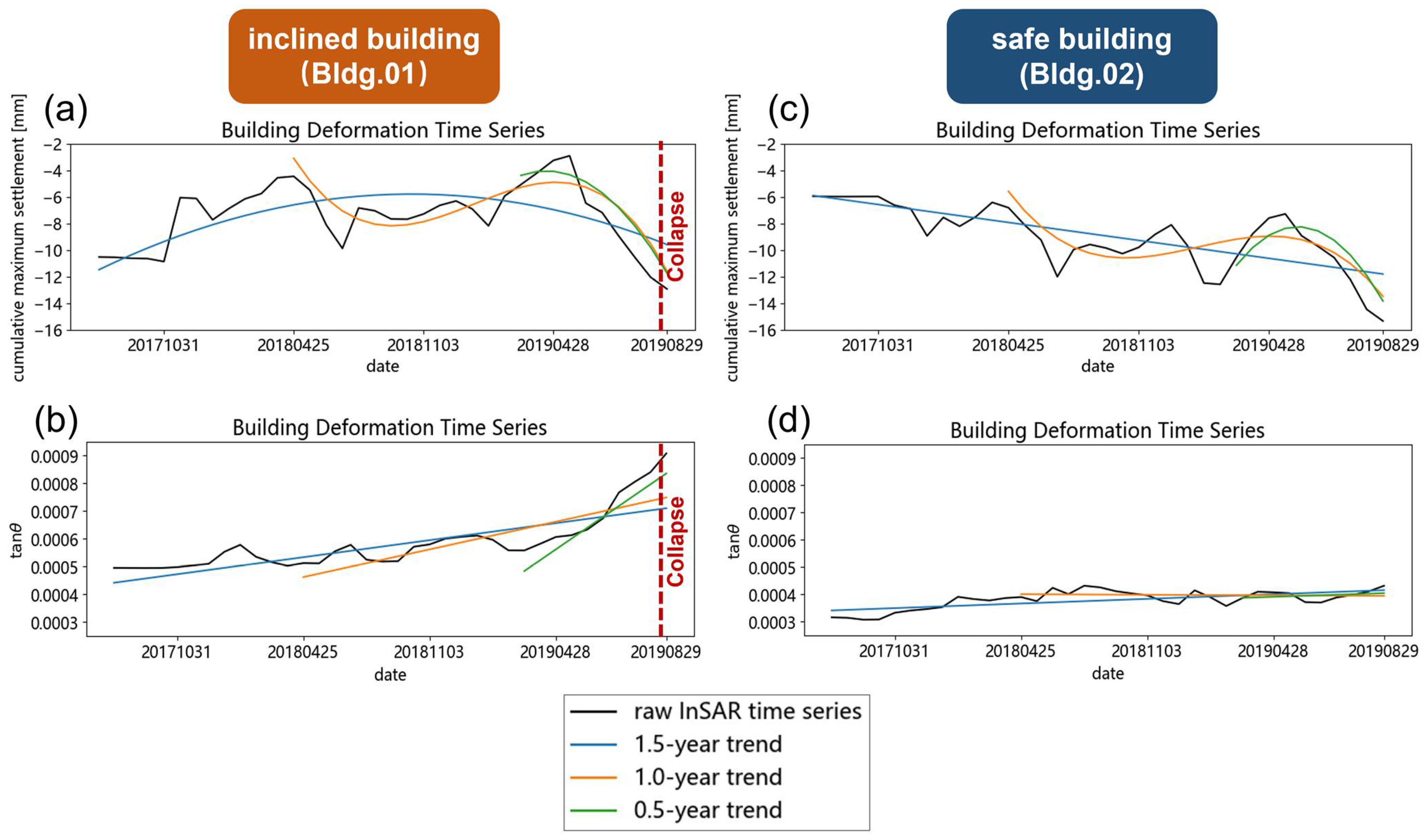
As shown in
Figure 9, the left-hand column is the fitting curves of the settlement index of the inclined Hepingxinju, and the right-hand side is the curves of the normal building for comparison. The top line of the graph represents the fitting curve of the accumulated maximum settlement, while the bottom line of the graph represents the fitting curve of the inclination angle, respectively. The black line represents the original time series data, and the blue, orange, and green lines represent the long-term, medium-term, and short-term fitting trends, respectively.
It is easy to identify that the cumulative sedimentation indices in the first row represent a long-term linear trend. As the time interval shortens, the trend fitting results become cubic and quadratic, respectively. This variation lies in the fact that the original cumulative settlement index has strong volatility in the medium and short term, resulting in the model used for trend analysis needing to increase its complexity to fit the local fluctuations of the data. When using this index to analyze the risk of a building, it is necessary to design sophisticated determination rules to describe this model’s complexity.
However, because short-term data have a stronger correlation with the current building risk status, this has a greater impact on the discrimination results. However, in the first row, the short-term trend curves of accumulated settlements show a rapid decline in accumulated settlements before the settlement and inclination incidents. Usually, a decrease in cumulative settlement represents a decrease in the risk of building safety. Therefore, it is impossible to give timely warning to the settlement and inclination incident only based on short-term trends in cumulative settlement.
Compared with the first row, the settlement inclination represented by the second row shows a clear linear trend in the long-term, medium-term, and short-term trends in the inclined building on the left, and the slopes of the three straight lines change significantly, with a clear acceleration trend. Based on this index, it is easy to determine that the risk of the Bldg.01 (Hepingxinju) is increasing, which is consistent with the fact that the data reflect the imminent inclined trend. It is also worth noting that, as has been marked in
Figure 7c, even though Hepingxinju finally collapsed, and the InSAR NSI retrospective analysis showed strong indication of its risky condition, the calculated
had a maximum value of 0.0009, which was still significantly less than the threshold of 0.004, given by the engineering specifications.
From the trend analysis in the second row on the right, which represents the condition of Bldg.02, the three trend curves almost overlap with each other. This shows that the NSI changed very little for a long time before the collapse of the adjacent Hepingxinju. According to the index, it is easy to determine that Bldg.02 is in a stable state, which is consistent with the fact that the data on the right reflect the safe status of the building.
Comparing the graphs in the first row and the second row, the time series shows obvious slope changes in the inclined Hepingxinju, whereas the index shows strong stability in the case of Bldg.02. Due to the high degree of discrimination displayed by the settlement inclination index in the two samples, efficient building safety risk analysis can be carried out by setting a reasonable threshold for this index.
4.2.3. Cause Analysis of the Incident
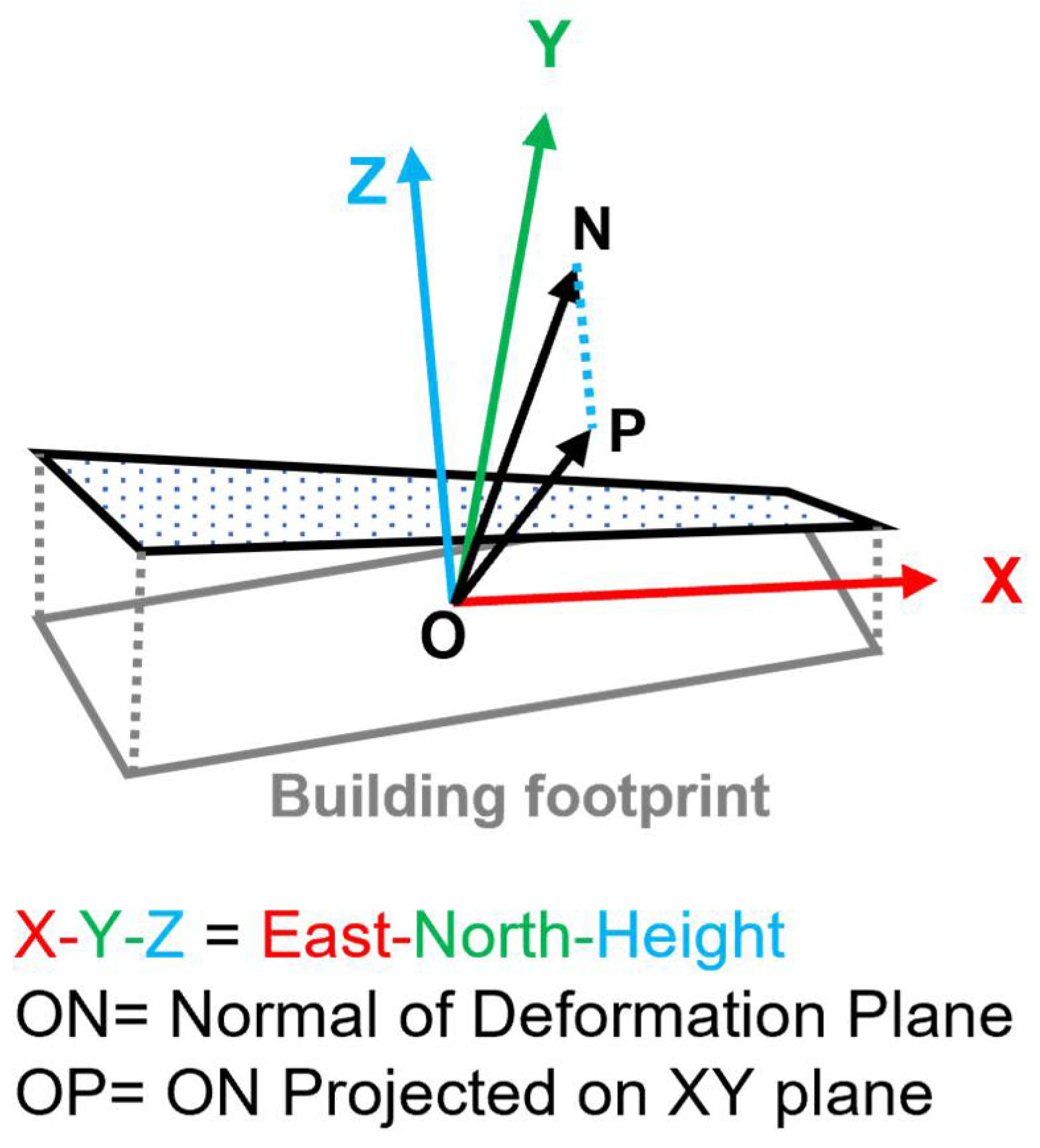
We also calculated the spatial orientation of the nonuniform settlement plane. The results showed that the settlement plane sank towards the northeast with an azimuth of 29 degrees with respect to the north orientation, as shown in
Figure 10.
According to the field investigation and analysis, it was found that the construction and the operation of Metro Line 9 were continuously disturbing the aging building at the northeast corner and its surrounding surface, resulting in a subsidence trend. Before the incident on 28 August 2019, the shield has not started tunneling, whilst grouting works has been implemented on 25 June 2019 at the southeast part of the building to prevent potential deformation caused by tunneling. The minimum horizontal distance between the grouting well to the building is only about four meters. The grouting works give the building an upward force on the southeast corner, which was opposite to the influence of Metro Line 9 on the northeast corner (see
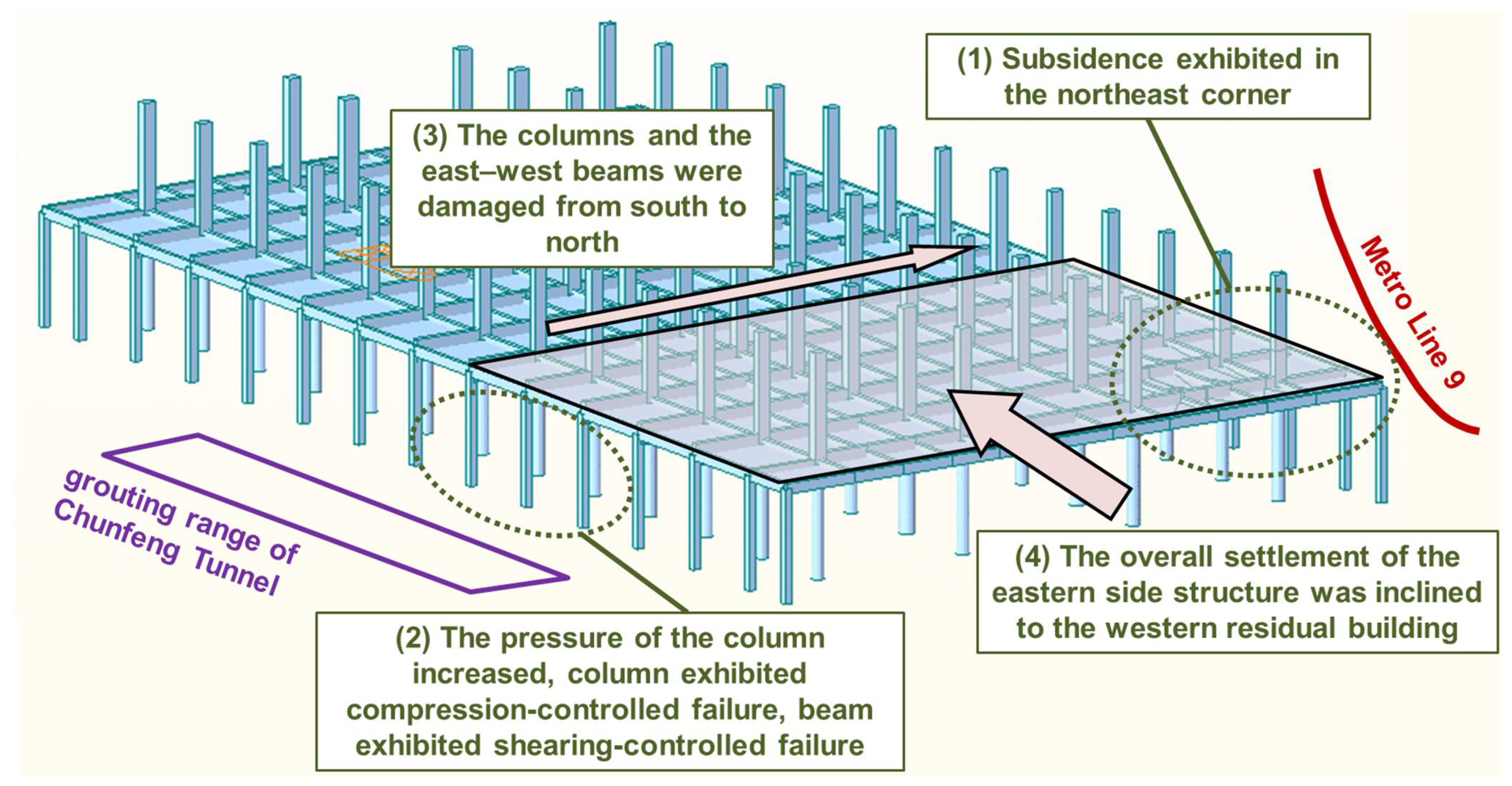
Figure 4b). The surrounding two underground works induced uneven deformation of the building. In addition, the concealed culvert caused corrosion and deterioration of the main stressed component. Consequently, the nonuniform settlement of the pile foundation cap was intensified; the northeast side caps of the building were separated from the foundation due to the large settlement. In this case, internal force was redistributed because the foundation bearing capacity of southwest was higher than others, and the southwest columns bore a larger superstructure weight. Then, as the pressure of the beam and column damage on the south side of axes 10 and 11 gradually increased, the column eventually exhibited compression-controlled failure; the east–west main beam also occurred shearing-controlled failure. Finally, the column and the east–west girder on the south side of axis 10 and axis 11 were damaging from south to north, and the overall settlement of the eastern side structure was inclined to the western residual part. The directions of inclination and collapse were highly consistent with InSAR NSI analysis, from the general comparison of
Figure 10 and
Figure 11.
4.3. Risk Analysis of Bldg.03–09
On the basis of the analysis of Bldg.01–02, seven aging buildings, marked as Bldg.03–09 along Chunfeng Tunnel, were introduced to further verify the effectiveness of the proposed NSI. As described in
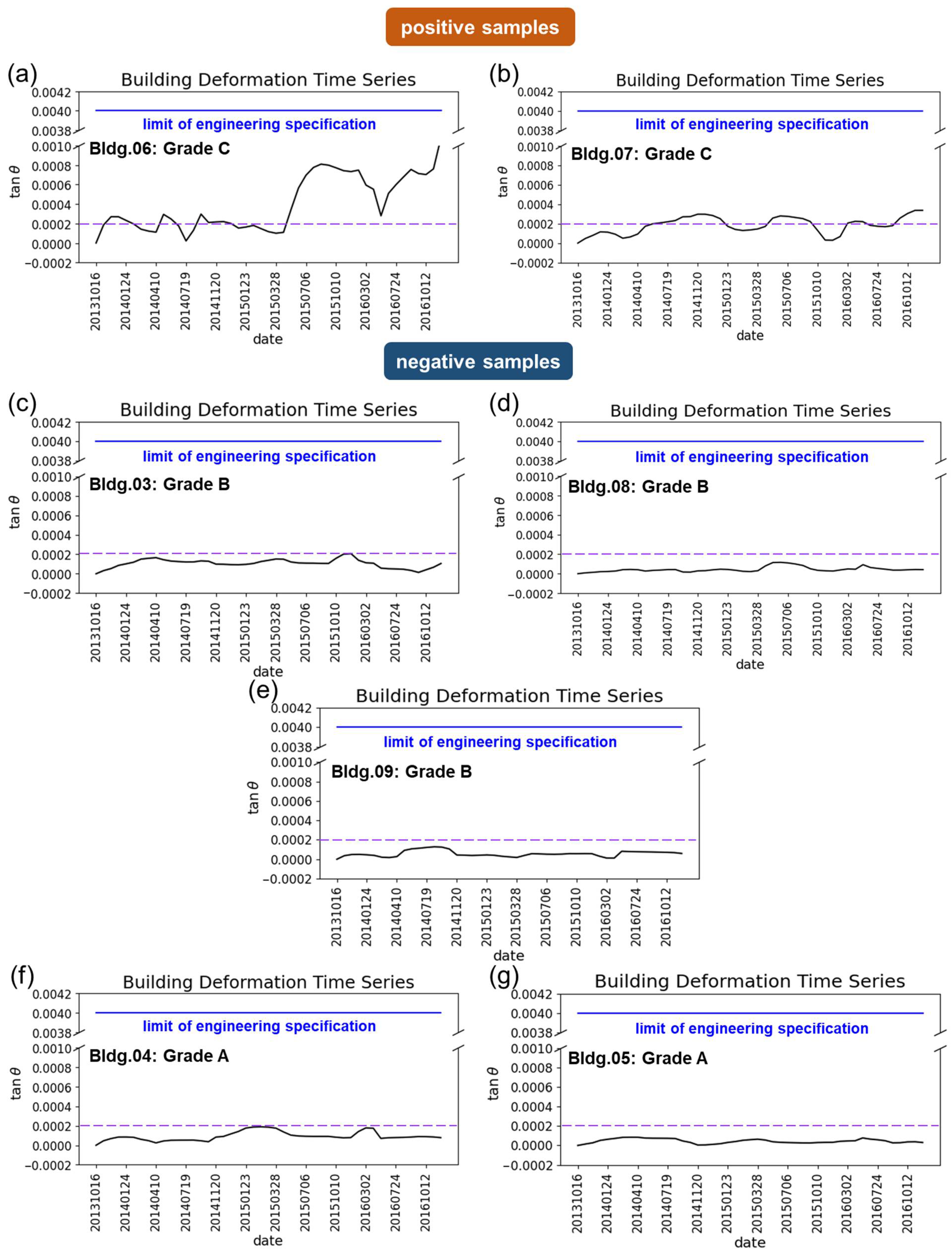
Section 3.2.2, the grades of each building were determined by following local standards. The standard defines the grades as follows. Grade A buildings can continue to be used or can be used after the necessary treatment of damage. Grade B buildings should be carefully observed, with damage properly addressed. When abnormal situations occur, structure testing is mandatory. Both these grades of building should be inspected every ten years and every five years, respectively. Grade C buildings require measures to be taken immediately, including structural tests, reinforcement, keeping the building unoccupied, or even demolition. Among the seven samples we collected, Bldg.06–07 were grade C, which we defined as positive samples; the other five buildings were grade A and B, which we defined as negative samples. The grades were specified in 2017, denoting the safety conditions of corresponding buildings at that time; NSI analysis was performed from 2013 to 2016, comparing between the grades.
Figure 12 depicts the nonuniform settlement curve of the seven buildings. Positive samples and negative samples exhibit significant differences in the variation in NSI. From
Figure 12a, the tangent value of the inclination angle reached 0.0009 at the grade C Bldg.06, which was equivalent to the value of Hepingxinju (0.0009 before collapse). Additionally, the other grade C building (Bldg.07 shown in
Figure 12b) had a maximum value of 0.0003. Even though this is much lower than that of Bldg.06, the time series also showed a value exceeding 0.0002 (marked with a purple dashed line in
Figure 12) in four periods, which almost accounted for half of the temporal domain. Among the negative samples, the values of Bldg.03, 08, 09, and 04 were generally lower than 0.0002 (see
Figure 12c–f). Additionally, Bldg.05 showed almost flat trends with values consistently lower than 0.0001, which coincided well with the safe conditions of grade A.
5. Discussion
In our study, we propose the NSI as an evaluation method of time-series InSAR. Compared with existing risk assessment methods, we suggest that the strength of the NSI is building-oriented, which may influence long-term structural health monitoring. Given that using too large a time series dataset for PSInSAR processing will result in a lack of PSs due to signal decorrelation, the available SAR data were divided into several continuous batches to perform time-series InSAR processing separately. Then, the calculated PSs were spliced together to form a complete long time series. In general, the PSs obtained by separate calculations did not coincide completely in space, which may have caused data mismatching as well as failure in generating long time series for the single PS. In our method, the full cluster of PSs was used to simulate the plane, which characterizes the status of the building rather than a single point at each temporal batch. In this way, the mismatching of PSs during different temporal batches has little influence on the proposed method. Moreover, the focus is shifted from monitoring each single point on a building to a quantitative index related to each building.
However, the proposed NSI still has limitations that need to be improved in future studies. First and foremost, the setting of a threshold is critical to risk assessments of building clusters. From a data-driven perspective, accurate determination of the threshold depends on sufficient samples, especially the proportion of positive samples to the overall samples, which is commonly unavailable. In our study, based on limited positive samples, we may preliminarily suggest that a value of 0.0009 indicates the risk of uneven subsidence in buildings. A more rigorous threshold could be given by quantitative and systematical comparison between space- and ground-based monitoring. From a mechanism-driven perspective, structure types, usages, foundations, geological conditions, and external disturbances should be taken into consideration. It is impossible to apply a set of fixed thresholds to assess all individual buildings in the area. For example, reaching values of 0.0009 during temporal evolution, Hepingxinju collapsed, and Bldg.09 remained standing, since these two buildings varied not only in location, but in many mechanical aspects as well. Therefore, the accurate index threshold still needs to be determined through the analysis of many samples in different scenarios.
Second, fluctuations exist in nonuniform settlement curves. Clusters of PSs corresponding to the top of the building were utilized to generate the NSI, with the thermal expansion component not being removed. We suggest that trend analysis can be an effective way to follow the overall temporal evolution in NSI, especially the short-term increase in the index that indicates the unsafety condition of a building.
Third, the requirement of NSI is crucial. Ideally, PSs identical in height should be evenly distributed on a building to enable correct estimation of the deformation plane. However, these requirements are hard to meet due to the side-looking geometry of satellite SAR sensors. We omitted buildings where fewer than 5 points were acquired, and applied the SVD-based least-square method to mitigate the effect of a degraded plane model. At the same time, the accuracy of PS geolocations and heights should be taken into account, because they both have strong impact on point extraction for individual buildings. In this study, we inflated the building footprint with a buffer of 2 m to compensate for the geolocation error of PSs, and set an empirical threshold of 10 m to filter the height of the PSs on each building roof. Additionally, these empirical parameters need to be adjusted for specific SAR data processing.
Last, the applicability of the method is still limited. The method developed in our study was tested on existing multistory buildings, particularly aging structures. Considering high-rise buildings, rare PSs can be used due to the limited extent of building footprints. In this situation, other indexes that characterize the safety conditions of buildings should also be introduced, such as the inclined condition generated by PSs on the facades.
6. Conclusions
This study developed a Nonuniform Settlement Index as a subsequent evaluation method of time-series InSAR monitoring. The NSI calculated the inclination angle and generated a 3D settlement plane for performing building risk assessments. Compared with screening by thresholds of the deformation rate and the cumulative settlement of specific points, it provides a more intuitive evaluation of buildings using complete spatio-temporal information of the building’s PSs. This new method was first applied to an aging building, Hepingxinju, which had inclined and subsequently collapsed on 28 August 2019 due to tunneling works and culvert erosion; Hepingxinju was assessed using X-band COSMO-SkyMed images. The Nonuniform Settlement Index of Hepingxinju PSs showed significant risk characteristics compared with an adjacent safe building. The settlement plane sank towards the northeast, with an azimuth of 29 degrees with respect to the north orientation, which is highly consistent with the conclusions of the investigation performed by the government into the incident. Further verification of the method on eight aging buildings demonstrated the positive effectiveness of the method. We suggest that such a methodology can be applied as a subsequent analyzing tool of time-series InSAR, which also has promising prospects in the risk management of building clusters over wide coverage.
