Abstract
Distributed array radar achieves high angular resolution and measurement accuracy, which could provide a solution to suppress digital radio frequency memory (DRFM) repeater jamming. However, owing to the large aperture of a distributed radar, the far-field plane wave assumption is no longer satisfied. Consequently, traditional adaptive beamforming methods cannot work effectively due to mismatched steering vectors. To address this issue, a DRFM repeater jamming suppression method based on joint range-angle sparse recovery and beamforming for distributed array radar is proposed in this paper. First, the steering vectors of the distributed array are reconstructed according to the spherical wave model under near-field conditions. Then, a joint range-angle sparse dictionary is generated using reconstructed steering vectors, and the range-angle position of jamming is estimated using the weighted L1-norm singular value decomposition (W-L1-SVD) algorithm. Finally, beamforming with joint range-angle nulling is implemented based on the linear constrained minimum variance (LCMV) algorithm for jamming suppression. The performance and effectiveness of proposed method is validated by simulations and experiments on an actual ground-based distributed array radar system.
1. Introduction
In recent years, repeater jamming generated by digital radio frequency memory (DRFM) technology [1] has severely threatened modern radar systems. DRFM jammers can generate a large number of active false targets similar to actual radar targets in time, frequency, and spatial domain [2], which may seriously affect radar target detection and tracking. Especially when jamming enters at the angle of the radar mainlobe, the jamming effect on the radar becomes more significant. To tackle this issue, the idea of using distributed radar systems to counter DRFM repeater jamming has been proposed and received attention [3]. Distributed radar consists of multiple spatially separated nodes working in synchronization, with high angular resolution, a wide detection range, and high node redundancy [4]. Therefore, in the field of electronic counter-countermeasures (ECCM), distributed array radar has broad prospects, and research on its anti-jamming methods is valuable.
Several studies have been conducted on anti-jamming methods for distributed array radar, but the total number of studies is still limited. Anti-jamming approaches for distributed radar systems consist of two aspects: one is to use the distributed array as a large-aperture, sparse-phased array and suppress jamming by beamforming methods; the other aspect is to consider the distributed array as a MIMO radar with widely separated antennas and use the difference between the target echo and the jamming signal received by each antenna to identify and suppress the jamming [5]. Regarding the first aspect, the authors of [3] proposed the basic idea of adding multiple distributed auxiliary arrays to a single array to suppress the jamming and used the MMSE and MSINR criteria to complete spatial jamming suppression. Based on this, the authors of [6,7] studied jamming suppression methods for wideband signals in distributed arrays using frequency-domain beamforming. The authors of [8] used an iterative adaptive approach (IAA) to reconstruct the jamming covariance matrix and used it as a training sample for mainlobe repeater jamming suppression. Reference [9] proposed a subarray-based joint beamforming method to save system degrees of freedom (DOFs) and computation. Reference [10] proposed a method that combines spatial mainlobe jamming cancellation and clutter suppression, which was applied to airborne distributed array platforms. Regarding the second aspect, reference [11] applied Fisher z-transform to determine target correlation, identify the target and jamming, and perform spatial filtering. Reference [12] applied joint blind-source separation methods to separate the target and main lobe jamming and used the separated signal form to design corresponding spatial filters to complete jamming suppression.
The distributed radar-jamming suppression methods mentioned above usually assume that the received signal satisfies the far-field plane wave assumption. However, in scenarios such as ground-based, large-aperture distributed radar and airborne distributed MIMO SAR, the equivalent aperture of the distributed array can be very large, and the angle at which the target signal arrives at each node may be different, so the received signal can no longer be approximated as a plane wave model. In this case, the problem of jamming suppression is transformed into the problem of near-field beamforming for a large-aperture array. Research on near-field beamforming methods for large-aperture arrays has mainly been conducted in the communication field, requiring signal coding [13,14]. In the radar field, reference [15] proposed a frequency-domain adaptive beamforming method based on the Fresnel model to improve beamforming accuracy in broadband scenarios. Reference [16] proposed a near-field high-resolution spatial filter based on a deconvolution beamformer. However, the above methods based on the Fresnel near-field signal model cannot accurately estimate the range parameters of the jamming, resulting in a decrease in the jamming suppression effect.
Inspired by the idea of space-time adaptive processing (STAP) [17] and space-fast-time adaptive processing (SFTAP) [18,19], a DRFM repeater jamming suppression method based on joint range-angle sparse recovery and joint range-angle beamforming is proposed. First, the joint range-angle two-dimensional (2D) steering vector is created based on the near-field spherical wave model. Then, a sparse dictionary within only the mainlobe scope is constructed, and weighted L1-SVD sparse recovery is proposed to estimate the jamming position. Subsequently, LCMV beamforming is carried out using jamming position estimation results for jamming cancellation.
This paper is developed as follows. In Section 2, the distributed array radar model and corresponding near-field signal model are established. In Section 3, the details of the proposed method are introduced. In Section 4, the advantages of the proposed method compared with other methods are verified by numerical simulations and experiments. The conclusion is presented in Section 5.
2. Signal Model of Distributed Array Radar
Large-aperture distributed array radar consists of one main array and several independent receiving auxiliary arrays, which are connected to an operation center and work cooperatively [20]. In this paper, one main array with a large aperture in meters and M auxiliary receiving arrays with smaller apertures are arranged to form the distributed array radar, as shown in Figure 1. The phase-center positions of each array are optimized by an adaptive genetic distributed radar node position optimization algorithm [21], which can suppress the grating lobe and maintain the equivalent mainlobe width. In the following description, we refer to a single main array or auxiliary array as a unit array.
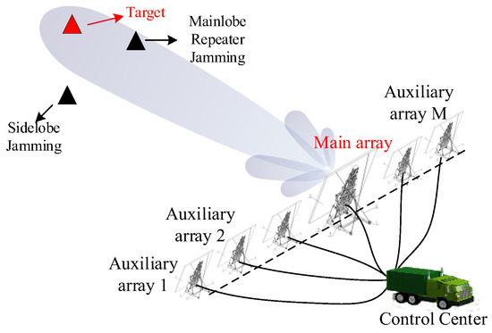
Figure 1.
Configuration of distributed array radar.
The chirp-form signal transmitted by a certain unit array can be expressed as
The target signal received by the unit array can be expressed as
Repeater jamming is performed by alternately acquiring and repeating a sampling paragraph of a radar-transmitted signal. This repeating is normally achieved by means such as direct repeating and repetitive repeating without losing generality, e.g., full-pulse repetitive repeating jamming. Assuming that there are a total of J jamming signals from different directions received by the unit array, the j-th jamming signal (j = 1, …, J) can be expressed as
where Aj is the amplitude of the jamming, L is the total number of false targets of sj, and tl is the time delay of the l-th false target. It can be seen from (3) that the pulse modulation rate and other characteristics of the jamming and the target are quite similar. Thus, a certain pulse compression (PC) gain can be obtained by jamming, and a series of false target peaks in different range units can be formed after pulse compression.
Because the auxiliary array and the main array can be used as one equivalent array after time-frequency synchronization, the array echo can be expressed as
where a(θ0) = [amain(θ0), aa1(θ0), …, aaM(θ0)] is the steering vector of the target signal, a(θj) = [amain(θj), aa1(θj), …, aaM(θj)] (j = 1, …, J) is the steering vector of the j-th jamming signal, and N(t) refers to array noise. Considering a far-field plane wave model, the far-field steering vector a(θ) can be expressed as
As for distributed array radar, its equivalent aperture can reach over several hundred meters. As a result, the distance from the signal source to the phase center of each unit array differs considerably, and the time delay from the target to a different unit array cannot be ignored. This time delay difference may lead to a signal amplitude envelope error and a phase error. Although the amplitude envelope can be corrected by time–frequency synchronization, the phase error in the steering vector model cannot be neglected. Thus, the signal model of the distributed array cannot be simply equivalent to the plane wave model. In this paper, the near-field spherical wave model is employed to revise the steering vector of the original far-field model. The spherical wave model is chosen instead of the Fresnel model mentioned in [15,16] because the Fresnel model is an approximate model of the spherical wave model after Taylor expansion. If the target’s position falls outside the range , the accuracy of the model decreases, resulting in performance degradation. As shown in Figure 2, assume that Rmain is the distance between the phase center of the main array and the signal source, and Rai (i = 1, …, M) is the distance between the phase center of each auxiliary array and the signal source. According to the cosine theorem, the distance between each unit array can be expressed as
where xmain is the position of the main array, and xai (i = 1, …, M) is the position of each auxiliary array.
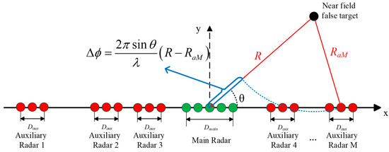
Figure 2.
Calculation of phase difference of jamming of different array elements under a near-field spherical wave model.
Then the near-field spherical wave model steering vector can be obtained as
Although the revised steering vector can improve the performance of spatial beamforming, there are still two obstacles that lead to the dissatisfactory performance of spatial beamforming. On the one hand, the spherical wave model needs range information to form an accurate steering vector, while the unknown range information about the jamming signal may lead to steering vector mismatch. On the other hand, when jamming occurs near or in the main lobe of the distributed array radar, beam distortion occurs and leads to heavier losses of target energy.
3. Proposed Jamming Suppression Method
The proposed joint range-angle sparse recovery and beamforming method can be implemented by following three main steps, as shown in Figure 3. First, the received signal is preprocessed by pulse compression and subarray-level sidelobe jamming cancellation. Secondly, the overcomplete basis for sparse recovery is created based on the revised spherical wave model steering vector. Next, jamming joint range-angle positions are estimated by the weighted L1 norm singular value decomposition (W-L1-SVD) method. Then, joint range-angle beamforming is proposed for jamming cancellation. Finally, the jamming residual and beam loss are judged, and the jamming estimation and beamforming processes are iterated until the jamming is fully suppressed and the beam loss reaches the lowest value.
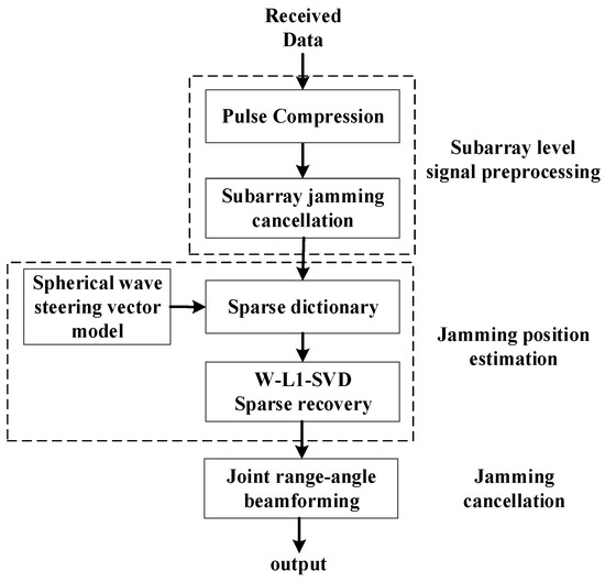
Figure 3.
Block diagram of the proposed method.
3.1. Sparse Dictionary Generation
Subarray-level jamming cancellation is proposed first to suppress the sidelobe jamming for each subarray to save the degree-of-freedom (DOF). Subarray-level sidelobe jamming cancellation adds an extra constraint to adaptive beamforming to maintain the mainlobe shape. Under constrained beamforming, only sidelobe jamming is cancelled, while DRFM repeater jamming and the target are preserved. Then, the jamming joint range-angle position is estimated with reference to the idea of SFTAP proposed in [18] and the idea of sparse recovery direction of arrival estimation proposed in [22]. Instead of a large number of slow-time samples used in STAP, echoes in one period of time (PRT) are used in proposed method. A range-angle data vector is generated for sparse recovery by transforming the array element fast time 6 × N two-dimensional echo matrix is into 6N × 1 one-dimensional echo vectors. The sparse recovery data vector of only one target-signal echo corresponding to any (θ, R) position can be represented as
where Xmain(t) is the pulse compression result of the echo received by the main array from (θ, R). Similarly, Xai(t) (i = 1, , M) is the pulse compression result of the echo received by each auxiliary array from (θ, R).
Noticing that the PC result of repeater jamming forms multiple sparse peaks in the joint range-angle plane, an overcomplete basis, also known as a sparse dictionary, can be generated for sparse recovery jamming position estimation. Since sidelobe jamming can be suppressed through subarray-level cancellation, a smaller dictionary can be created within the mainlobe area instead of using the whole airspace. The small dictionary also reduces the computation of sparse recovery. Specifically, is the angle scope within the mainlobe area, and is the range scope covering the range corresponding to the time duration in one PRT. To construct the sparse dictionary, (θ, R) is traversed at a certain interval to construct the following matrix:
where .
The sparse dictionary is constructed by vectorizing by column, which can be expressed as
3.2. W-L1-SVD Sparse Recovery for Jamming Position Estimation
Similar to constructing a data vector corresponding to any (θ, R) position in (8), the pulse compression result of distributed array echo is used to construct a data vector. Assuming that the array echo S(t) defined in (4) is pulse-compressed to Y, the data vector of Y can be obtained as follows
Then, the data vector of the distributed array echo () can be proposed by the following sparse representation:
where B is the sparse vector with a sparsity of Q containing the range-angle information of signal sources.
In this paper, the L1-SVD method [23] is used to solve the sparse recovery problem. The L1-SVD method uses singular value decomposition (SVD) to reduce the dimension of the received data matrix and extracts the signal subspace for signal estimation. The algorithm first performs SVD on the echo data, which can be expressed as
where U and V are matrices composed of the left singular vector and the right singular vector of XT, respectively. The elements on the diagonal of Λ are the singular values of XT and are arranged in descending order. The dimension of XT is reduced by using the results of SVD:
where , is the identity matrix, and P is the number of signals. The elements on the diagonal of Λ are the singular values of X and are arranged in descending order. Similarly, , and . Then, (14) can be replaced by
Thus, the L1 norm minimization constraint model can be expressed as
where β is a hyperparameter related to the noise level; and , in which is the L2 norm of all elements in row Q of matrix B, that is
However, the L1-SVD method suffers from pseudo-peaks and peak offset under low interference-to-noise ratio (INR) conditions because the algorithm directly imposes the L1 norm constraint on the sparse recovery instead of the L0 norm constraint. The L0 norm of the vector only exists as 0 or 1, so the contribution of large coefficients and small coefficients to the objective function is the same. However, in the L1 norm constraint model, the contributions of large coefficients and small coefficients to the objective function are different. The modulus corresponding to a large coefficient is large, and the corresponding contribution is relatively large, and vice versa. To ensure the convergence of the objective function, the constraints on large coefficients must be larger, and the constraints on small coefficients must be smaller. Since small coefficients usually correspond to noise components, in noisy scenes, the noise components are difficult to be strictly constrained. As a result, the performance of the algorithm is reduced.
To solve this problem, a weighted L1 norm constraint SVD method, namely the W-L1-SVD method, is applied. By weighting the norm constraint model, the large coefficient in the constraint model is subject to a small weight penalty, and the small coefficient is subject to a large weight penalty. This adaptive adjustment mechanism enables the weighted L1 norm constraint model to better approximate the L0 norm model. The specific steps are as follows.
When performing SVD in (13), U is separated into signal subspace (Us) and noise subspace (Un).
It can be proven that the signal subspace spanned by the noise subspace (Un) and the array manifold matrix (A) is orthogonal. Considering the relationship between the overcomplete basis set () and the array manifold (A), can be written as
By using the orthogonal properties between signal subspace and noise subspace,
the weight vector can be written as
where and . The updated optimization model can be expressed as
The optimization problem can be solved by cone programming software packages such as the CVX toolbox [24]. After the sparse vector is obtained, joint range-angle position estimation of jamming can be performed by searching the corresponding peaks in the sparse dictionary. In this paper, the number of peaks in the range domain is used to identify the target and jamming. After obtaining a sparse recovery range-angle two-dimensional plane, a signal from a single angle with only one peak is considered a target. On the contrary, a signal from a single angle with multiple peaks is considered jamming.
3.3. Beamforming with Joint Range-Angle Nulling
Range-angle joint beamforming with multiple nulling is performed using the jamming position estimation results obtained by sparse recovery. The joint beamforming weight is constructed according to the linear constrained minimum variance (LCMV) criterion.
When the range-angle position of DRFM repeater jamming is known, the linear constrained minimum variance (LCMV) criterion makes the output power,
reach its minimum value under constraint
where is the linear constraint using the jamming position estimation results, is the covariance matrix of YT, and . In a practical situation, the constraint of target is not a priori knowledge, the target position information of the previous PRT is used as the target position, and an iterative process is proposed in the LCMV beamforming process to obtain more accurate .
The initial values for iteration are set to the target range and angle at the previous pulse repetition time (PRT) before the distributed radar receives jamming during the tracking process. The estimated target peak () in the PC result after jamming suppression is used to modify . The angle value is obtained by traversing within a certain range around the initial angle and selecting the angle value with the smallest target loss. Through iteration, the target position can be updated until the number of cycle iterations reaches the limit or the signal loss reaches the minimum.
According to the Lagrange multiplier method, the 2D beamforming weight vector can be calculated as
After using the modified weighted vector, a series of nulls at the joint range-angle positions of false targets is formed. As a result, the false targets caused by DRFM repeater jamming can be suppressed. The LCMV weight vector is applied to the data vector of the distributed array received echo, and the output result pointing to the target position can be obtained.
4. Numerical Simulations and Experimental Analysis
In this section, the performance of the proposed method is verified by numerical simulation and experiments based on a ground-based air detection distributed array radar system. The results are as follows.
4.1. Numerical Simulation Analysis
In the numerical simulation section, a one-dimensional large-aperture distributed array radar system that consists of one main array and five auxiliary arrays is arranged. The positions of unit arrays of the distributed array are designed to form a non-uniform sparse linear array using the adaptive genetic algorithm proposed in [21] for grating lobe suppression. The detailed simulation parameters are shown in Table 1. The mainlobe width of the main radar is 2°, and the equivalent mainlobe width of the distributed array is calculated as 0.1°. The performance of the proposed method is studied and compared with the JADBF [9], SFTAP [19], and JBSS [12] methods. To fully verify the effectiveness and universality of the method, the proposed method and other methods are tested in single-jamming and two-jamming situations.

Table 1.
Simulation parameter settings.
The sparse recovery estimation results of simulated jamming signals obtained by W-L1-SVD are shown in Figure 4. As seen from Figure 4, the false target position of single jamming and two jamming can both be accurately displayed by the W-L1-SVD method. The range-angle position of jamming peaks can be further extracted by detecting the two-dimensional peak position of sparse recovery results.
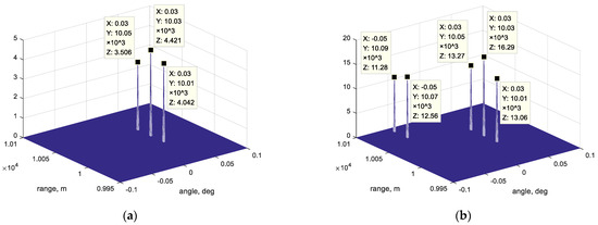
Figure 4.
Jamming peaks estimated by W-L1-SVD: (a) single jamming; (b) two jamming.
After joint range-angle position estimation, range-angle joint beamforming with multiple nulling is performed to form multiple nulls. Figure 5 shows the range-angle joint beam pattern formed by the proposed range-angle joint beamforming method and the SFTAP method for comparison. It can be seen from the figure that joint range-angle nulls can be generated at the estimated jamming position by the proposed 2D-LCMV beamforming method, while the peak value at the joint range-angle position is not reduced. Moreover, the mainlobe at target range unit is also not offset, which proves the accuracy of the proposed near-field spherical wave-steering vector model. In comparison, the SFTAP method cannot accurately form nulls in both single-jamming and two-jamming situations, and the mainlobe offset is severe because of the mismatch between the steering vectors used in the SFTAP method and the near-field steering vector model.
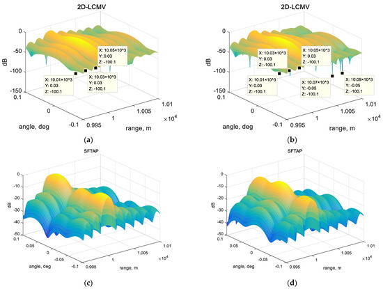
Figure 5.
Range-angle joint beam pattern of (a) the proposed method in a single-jamming situation, (b) the proposed method in a two-jamming situation, (c) SFTAP in a single-jamming situation, and (d) SFTAP in a two-jamming situation.
To further compare the performance of the proposed method with that of other DRFM repeater jamming suppression methods, the beam patterns of the proposed method, SFTAP, JADBF, and JBSS and the ideal quiescent pattern, are shown in Figure 6 and Figure 7, respectively. In the one-jamming situation, the beam pattern of the proposed method shown in Figure 6a is sliced from the target signal range unit (10 km) of the 2D beam pattern, and the pattern shown in Figure 6b is sliced from the first false target jamming range unit (10.01 km) of the beam pattern. Similarly, the beam patterns in Figure 7a–c are sliced from 10 km, 10.01 km (corresponding to the jamming in 0.03°), and 10.07 km (corresponding to the jamming in −0.05°). As can be found from Figure 6a, the pattern of the proposed method is more consistent with the quiescent pattern, which means the proposed method may achieve lower target loss. However, other methods suffer from pattern offset and target loss. As shown in Figure 6b, the proposed method can form more accurate and deeper nulls than the compared methods, resulting in a lower jamming residual. Beam patterns of the JADBF and JBSS are similar in Figure 6a,b, while the proposed method and SFTAP show significant differences because JADBF and JBSS are spatial-domain methods. The beam patterns of these two methods do not change with the range. The beam pattern of the proposed method and that of the SFTAP method may change with the range because these methods impose constraints on both range and angle. Similar conclusions can be found in Figure 7 corresponding to two-jamming situations. The proposed method shows better performance in maintaining the target signal and accurate jamming cancellation compared with the other methods.
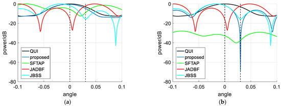
Figure 6.
Beam patterns of the proposed method and comparison methods in a single-jamming situation: (a) at the target range unit; (b) at the jamming range unit.
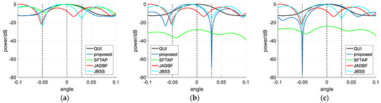
Figure 7.
Beam patterns of the proposed method and comparison methods in a two-jamming situation: (a) at the target range unit; (b) at the jamming range unit corresponding to 0.03°; (c) at the jamming range unit corresponding to −0.05°.
The pulse compression results of the proposed method, JADBF, SFTAP, and JBSS are shown in Figure 8. It can be seen that the target PC peak of the proposed method can be accurately detected. On the other hand, the comparison methods suffer from serious jamming residuals, and the target PC peak is difficult to accurately detect. It can also be seen that in the two-jamming situation, the peaks caused by jamming residuals in the comparison methods are more numerous and higher in amplitude. In particular, the JBSS method shows much worse performance because of the misjudgment of the target channel after the separation of the target and jamming channel.
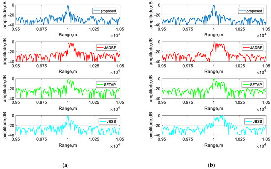
Figure 8.
Pulse compression results of the proposed method and comparison methods: (a) in a single-jamming situation; (b) in a two-jamming situation.
For further comparison of the performance of the proposed method and other methods, the output signal-interference-to-noise ratio (SINR) versus input signal-to-noise ratio (SNR) of the proposed method, SFTAP, JADBF, and JBSS are shown in Figure 9. It is found that the output SINR of the proposed method is better than the output SINR of SFTAP, JADBF, and JBSS. This is because the proposed method achieves lower target loss and less jamming residual compared with other methods.
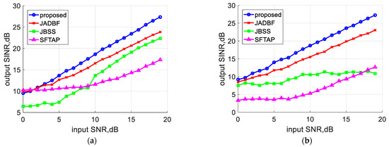
Figure 9.
Output SINR versus input SNR of the proposed method and comparison methods: (a) in a single-jamming situation; (b) in a two-jamming situation.
In practical situations, array calibration error is often non-negligible. Array calibration error includes the antenna location error and mutual coupling error, resulting in subarray-level amplitude and phase differences. The calibration error may cause mainlobe offset and target degradation after utilizing the proposed method. Additional simulation results validate the effects of calibration error, as shown in Figure 10 below. In this simulation, 10% array position error is added to the received signal. Comparing Figure 10 with Figure 9a, it can be observed that both the proposed method and the comparison method experience a small decrease in output SINR when calibration error occurs.
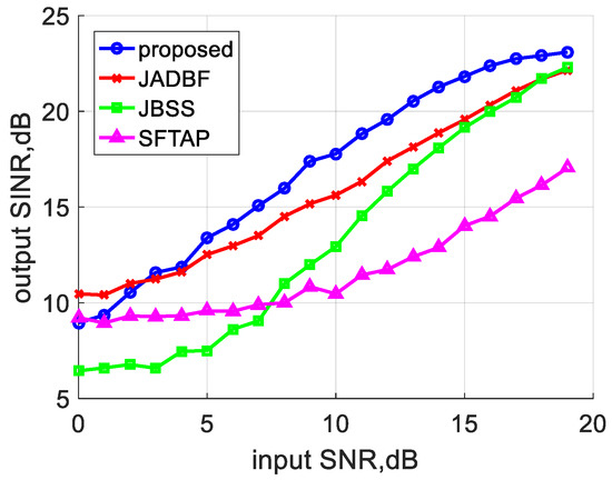
Figure 10.
Output SINR versus input SNR of the proposed method and comparison methods with calibration error.
4.2. Experimental Analysis
The experimental data of a ground-based distributed array radar system are used to verify and analyze the proposed algorithm. The experimental scene is shown in Figure 11. The array arrangement is similar to the distributed array radar used in the simulation part and is used to detect high-altitude civil aircraft targets at an elevation angle of 20°. The azimuth aperture of the distributed array is 100 m, and the position of auxiliary arrays are also optimized by the algorithm in [21]. The aperture of the distributed array radar used in the experiment is 100 m. The position of each subarray is [0, 28.57, 34.22, 42.94, 52.55, 100], and the main array is located at 34.22 m. The mainlobe width of the main array is 1°, the mainlobe width of each auxiliary array is 5°, and the mainlobe width of the whole DAR is 0.11°. The jamming is transmitted by a large unmanned aerial vehicle (UAV), and the time delay is added in advance to approximate the real jammer position. In the experimental environment, a dense false target jamming signal with 20 false peaks comes from 0.112°, the target signal comes from 0°, the target distance is 15.21 km, and input SNR is evaluated as 20 dB after pulse compression.
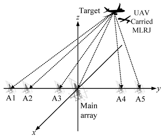
Figure 11.
Schematic diagram of the experimental scene.
The jamming position estimation results obtained using the experimental data are shown in Figure 12, and the range-angle joint beam pattern of the proposed method is shown in Figure 13. It can be seen from these figures that the proposed method can accurately estimate the location of jamming false target peaks, and the corresponding nulls can be formed by the joint beamforming method. The target can also be maintained in the joint beam pattern.
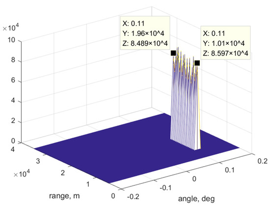
Figure 12.
Jamming position estimation results obtained using experimental data.
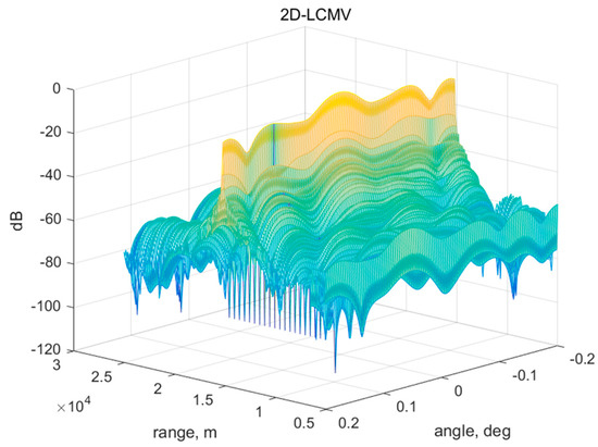
Figure 13.
Range-angle joint beam pattern of the proposed method obtained using experimental data.
The pulse compression results before and after jamming cancellation obtained by the proposed method and comparison methods are shown in Figure 14. The signal can be correctly detected, while comparison methods cannot fully suppress the jamming or have target loss. The output SINRs of the proposed method and comparison methods based on 20 received pulses are shown in Figure 15, and the average SINR improvement is calculated and shown in Table 2. It is obvious that the proposed method can obtain better anti-jamming results than other methods, and the average SINR improvement reaches more than 3.72 dB. During the experiment, the impact of calibration error was reduced by two-stage calibration using a signal calibration tower and unmanned aerial vehicles. As a result, good anti-jamming performance is shown in the experimental results.
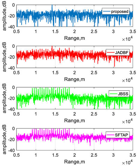
Figure 14.
Pulse compression results of the proposed method and comparison methods obtained using experimental data.
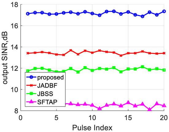
Figure 15.
Output SINR of the proposed method obtained using experimental data.
Table 2.
Average output SINR of various methods.
5. Conclusions
A DRFM repeater jamming suppression beamforming method based on joint range-angle sparse recovery and joint range-angle beamforming for distributed array radar is proposed in this paper. In the proposed method, the steering vectors of a distributed array are reconstructed according to the spherical wave model under near-field conditions. Then, the L1-SVD sparse recovery method with a two-dimensional sparse dictionary is proposed to estimate the range-angle position of jamming. Finally, beamforming with joint range-angle nulling is performed for jamming suppression. The proposed method can enhance the anti-jamming performance of distributed array radar in the presence of multiple DRFM repeater jamming.
Author Contributions
B.H. performed the theoretical study, conducted the experiments, processed the data, and wrote the manuscript. X.Q. helped with the theoretical study, provided research suggestions, and revised the manuscript. X.Y. provided the experimental equipment and revised the manuscript. W.L. and Z.Z. helped in performing the experiments and provided suggestions for the manuscript. All authors have read and agreed to the published version of the manuscript.
Funding
This research was supported by the National Natural Science Foundation of China (NSFC) under grant 61860206012.
Data Availability Statement
The data presented in this study are available on request from the corresponding author. The data are not publicly available due to confidentiality requirements.
Conflicts of Interest
The authors declare no conflict of interest.
References
- Sparrow, M.J.; Cikalo, J. ECM Techniques to Counter Pulse Compression Radar. U.S. Patent 7,081,846, 25 July 2006. [Google Scholar]
- He, X.; Liao, K.; Peng, S.; Tian, Z.; Huang, J. Interrupted-Sampling Repeater Jamming-Suppression Method Based on a Multi-Stages Multi-Domains Joint Anti-Jamming Depth Network. Remote Sens. 2022, 14, 3445. [Google Scholar] [CrossRef]
- Yang, X.; Yin, P.; Zeng, T.; Sarkar, T.K. Applying Auxiliary Array to Suppress Mainlobe Interference for Ground-Based Radar. Antennas Wirel. Propag. Lett. 2013, 12, 433–436. [Google Scholar] [CrossRef]
- Nanzer, J.A.; Mghabghab, S.R.; Ellison, S.M.; Schlegel, A. Distributed Phased Arrays: Challenges and Recent Advances. IEEE Trans. Microw. Theory Techn. 2021, 69, 4893–4907. [Google Scholar] [CrossRef]
- Haimovich, A.M.; Blum, R.S.; Cimini, L.J. MIMO Radar with Widely Separated Antennas. IEEE Signal Process. Mag. 2008, 25, 116–129. [Google Scholar] [CrossRef]
- Zhang, H.; Luo, J.; Chen, X.; Liu, Q.; Zeng, T. Whitening Filter for Mainlobe Interference Suppression in Distributed Array Radar. In Proceedings of the 2016 CIE International Conference on Radar (RADAR), Guangzhou, China, 10–13 October 2016; pp. 1–5. [Google Scholar]
- Li, S.; Zhang, H.; Yang, X.; Sun, Y.; Liu, Q. Spatial Multi-Interference Suppression Based on Joint Adaptive Weight for Distributed Array Radar. In Proceedings of the 2019 IEEE Radar Conference (RadarConf), Boston, MA, USA, 22–26 April 2019; pp. 1–5. [Google Scholar]
- Chen, J.; Chen, X.; Zhang, H.; Zhang, K.; Liu, Q. Suppression Method for Main-Lobe Interrupted Sampling Repeater Jamming in Distributed Radar. IEEE Access 2020, 8, 139255–139265. [Google Scholar] [CrossRef]
- Chen, X.; Shu, T.; Yu, K.-B.; He, J.; Yu, W. Joint Adaptive Beamforming Techniques for Distributed Array Radars in Multiple Mainlobe and Sidelobe Jammings. Antennas Wirel. Propag. Lett. 2020, 19, 248–252. [Google Scholar] [CrossRef]
- Miao, Y.; Liu, F.; Liu, H.; Li, H. Clutter Jamming Suppression for Airborne Distributed Coherent Aperture Radar Based on Prior Clutter Subspace Projection. Remote Sens. 2022, 14, 5912. [Google Scholar] [CrossRef]
- Zhao, S.; Liu, Z. Deception Electronic Counter-countermeasure Applicable to Multiple Jammer Sources in Distributed Multiple-radar System. IET Radar Sonar Navig. 2021, 15, 1483–1493. [Google Scholar] [CrossRef]
- Ge, M.; Cui, G.; Kong, L. Mainlobe Jamming Suppression for Distributed Radar via Joint Blind Source Separation. IET Radar Sonar Navig. 2019, 13, 1189–1199. [Google Scholar] [CrossRef]
- Cui, M.; Dai, L.; Schober, R.; Hanzo, L. Near-Field Wideband Beamforming for Extremely Large Antenna Arrays. arXiv 2021, arXiv:2109.10054. [Google Scholar]
- Ramezani, P.; Björnson, E. Near-Field Beamforming and Multiplexing Using Extremely Large Aperture Arrays. arXiv 2022, arXiv:2209.03082. [Google Scholar]
- Zhang, Y.; Wu, X.; You, C. Fast Near-Field Beam Training for Extremely Large-Scale Array. IEEE Wirel. Commun. Lett. 2022, 11, 2625–2629. [Google Scholar] [CrossRef]
- Liang, J.; Zhang, T.; Xu, W.; Zhao, H. A Linear Near-Field Interference Cancellation Method Based on Deconvolved Conventional Beamformer Using Fresnel Approximation. IEEE J. Ocean. Eng. 2023, 48, 365–371. [Google Scholar] [CrossRef]
- Yang, X.; Sun, Y.; Yang, J.; Long, T.; Sarkar, T.K. Discrete Interference Suppression Method Based on Robust Sparse Bayesian Learning for STAP. IEEE Access 2019, 7, 26740–26751. [Google Scholar] [CrossRef]
- Rosenberg, L.; Gray, D.A. Constrained Fast-Time STAP for Interference Suppression in Multichannel SAR. IEEE Trans. Aerosp. Electron. Syst. 2013, 49, 1792–1805. [Google Scholar] [CrossRef]
- Björklund, S.; Nelander, A.; Pettersson, M.I. Fast-Time and Slow-Time Space-Time Adaptive Processing for Bistatic Radar Interference Suppression. In Proceedings of the 2015 IEEE Radar Conference (RadarCon), Arlington, VA, USA, 10–15 May 2015; pp. 0674–0678. [Google Scholar]
- Coutts, S.; Cuomo, K.; McHarg, J.; Robey, F.; Weikle, D. Distributed Coherent Aperture Measurements for Next Generation BMD Radar. In Proceedings of the Fourth IEEE Workshop on Sensor Array and Multichannel Processing, Waltham, MA, USA, 12–14 July 2006; pp. 390–393. [Google Scholar]
- Yang, X.; Li, Y.; Liu, F.; Lan, T.; Teng, L.; Sarkar, T.K. Antenna Position Optimization Method Based on Adaptive Genetic Algorithm with Self-Supervised Differential Operator for Distributed Coherent Aperture Radar. IET Radar Sonar Navig. 2021, 15, 677–685. [Google Scholar] [CrossRef]
- Hu, N.; Ye, Z.; Xu, D.; Cao, S. A Sparse Recovery Algorithm for DOA Estimation Using Weighted Subspace Fitting. Signal Process. 2012, 92, 2566–2570. [Google Scholar] [CrossRef]
- Xu, X.; Shen, M.; Wu, X.; Wu, D.; Zhu, D. Direction of Arrival Estimation Based on Modified Fast Off-grid L1-SVD. Electron. Lett. 2021, 58, 32–34. [Google Scholar] [CrossRef]
- Malioutov, D.; Cetin, M.; Willsky, A.S. A Sparse Signal Reconstruction Perspective for Source Localization with Sensor Arrays. IEEE Trans. Signal Process. 2005, 53, 3010–3022. [Google Scholar] [CrossRef]
Disclaimer/Publisher’s Note: The statements, opinions and data contained in all publications are solely those of the individual author(s) and contributor(s) and not of MDPI and/or the editor(s). MDPI and/or the editor(s) disclaim responsibility for any injury to people or property resulting from any ideas, methods, instructions or products referred to in the content. |
© 2023 by the authors. Licensee MDPI, Basel, Switzerland. This article is an open access article distributed under the terms and conditions of the Creative Commons Attribution (CC BY) license (https://creativecommons.org/licenses/by/4.0/).