Article

Collaborative Trajectory Planning and Resource Allocation for Multi-Target Tracking in Airborne Radar Networks under Spectral Coexistence

1
Key Laboratory of Radar Imaging and Microwave Photonics (Nanjing University of Aeronautics and Astronautics), Ministry of Education, Nanjing 210016, China
2
No. 8511 Research Institute of CASIC, Nanjing 210007, China
3
Department of Engineering, Durham University, Durham DH1 3DE, UK
4
Beijing Institute of Control and Electronics Technology, Beijing 100045, China
*
Author to whom correspondence should be addressed.
These authors contributed equally to this work.
Remote Sens. 2023, 15(13), 3386; https://doi.org/10.3390/rs15133386
Submission received: 18 May 2023 / Revised: 5 June 2023 / Accepted: 8 June 2023 / Published: 3 July 2023
(This article belongs to the Special Issue Advances in Radar Systems for Target Detection and Tracking)

Abstract

:
This paper develops a collaborative trajectory planning and resource allocation (CTPRA) strategy for multi-target tracking (MTT) in a spectral coexistence environment utilizing airborne radar networks. The key mechanism of the proposed strategy is to jointly design the flight trajectory and optimize the radar assignment, transmit power, dwell time, and signal effective bandwidth allocation of multiple airborne radars, aiming to enhance the MTT performance under the constraints of the tolerable threshold of interference energy, platform kinematic limitations, and given illumination resource budgets. The closed-form expression for the Bayesian Cramér–Rao lower bound (BCRLB) under the consideration of spectral coexistence is calculated and adopted as the optimization criterion of the CTPRA strategy. It is shown that the formulated CTPRA problem is a mixed-integer programming, non-linear, non-convex optimization model owing to its highly coupled Boolean and continuous parameters. By incorporating semi-definite programming (SDP), particle swarm optimization (PSO), and the cyclic minimization technique, an iterative four-stage solution methodology is proposed to tackle the formulated optimization problem efficiently. The numerical results validate the effectiveness and the MTT performance improvement of the proposed CTPRA strategy in comparison with other benchmarks.

1. Introduction

For the past few years, airborne radar networks have been gaining popularity and attention from technologists in different military and research organizations. The resulting great advantages over traditional static radar systems, such as the enhanced degree of freedom in geometric diversity and high flexibility and mobility of airborne platforms, can deliver powerful capabilities and better system performances for remote sensing, area surveillance, target detection, multi-target tracking (MTT), and parameter estimation [1,2]. To best utilize the potential of airborne radar networks, resource-aware scheduling is of crucial importance in different missions, which has been a research hot issue thus far.

1.1. Literature Review and Motivation

In principle, the resource-aware scheduling problem is built as a mathematical problem of optimizing the objective utility function while meeting some resource constraints, which can be divided into two typical categories according to the type of task purpose. The first type is to maximize the system performance for various applications in the context of satisfying the available system conditions [3,4,5,6,7,8,9,10,11,12]. As an example, in [3], the authors propose a joint node selection and power allocation algorithm for MTT in decentralized radar networks, which utilizes the feedback information in the tracking recursion to implement the appropriate resource allocation, aiming to improve the worst-case tracking accuracy. The work in [4] develops joint detection threshold optimization and the dwell time allocation scheme in order to minimize the MTT error in asynchronous radar networks, and a three-step-based solution is adopted to deal with the underlying optimization problem. In [5], an online joint beam and power scheduling approach is developed for distributed multi-target tracking in networked colocated multiple-input multiple-output (MIMO) radar systems, which controls the generated beams and the emitted power of multiple radar nodes to fulfill MTT and reduce the communication requirements. Taking the beampattern design into account, Sun et al. [6] investigate cooperative radar scheduling and the beampattern design for MTT in a networked colocated MIMO radar system. The authors of [7] focus on composed resource management for MTT in active and passive radar networks, the purpose of which is to collaboratively optimize the illumination resources of active radars and receive processing resources from passive radars to enhance the MTT performance. The studies in [8,9] apply the idea of time and aperture allocation to the inverse synthetic aperture radar imaging area. Other related studies can be found in [10,11,12].
For resource-aware applications, another requirement is to limit the total resource consumption of the radar system while meeting the predefined performance demands in order to maintain a low probability of interception (LPI) and prolong its lifetime [13,14,15,16]. Reference [17] presents a cooperative route design and multidimensional resource management algorithm for airborne radar networks, which aims to reduce the predicted Bayesian Cramér–Rao lower bound (BCRLB) for single target tracking and intercepted performance simultaneously by jointly adjusting the flight path and probing the resources of each airborne radar for some system constraints. Since the direct resource minimization algorithm might not result in a feasible solution when the available illumination resource is not sufficient to track all the targets with the predetermined accuracies, Yuan et al. [18] put forward a robust power allocation strategy for MTT with colocated MIMO radars, which minimizes the resource consumption while considering the importance levels of different tracked targets. In [19], Shi et al. combine the transmit resource management and waveform selection sub-problems into a unified problem and develop a joint optimization algorithm for target tracking in a decentralized phased array radar network. The resulting problem is built as a bi-objective optimization model, and an efficient three-step solution method is presented to tackle it efficiently. Other related work can be found in [20,21,22,23,24].
Although the above fruitful studies provide us some promising approaches to deal with transmit resource scheduling problems in networked radar systems, there are still some open issues in resource-aware management that should be highlighted and further addressed. Due to the increasing congestion of the radio spectrum, the coexistence between radar and communication systems has raised serious compatibility problems [25]. Numerous studies in the last few years have proposed various techniques to enable spectrum sharing for radar and communications and made seminal contributions to the field of spectral coexistence [26,27,28]. Nevertheless, the works in [6,7,8,9,10,11,12,13,14,15,16,17,18,19,20,21,22,23,24] do not take the spectrum sharing paradigm with communication systems into account. In such a case, the spectral coexistence will result in harmful interference between the two systems and have a direct and great impact on resource allocation schemes. It is inaccurate to adopt a BCRLB that has been calculated in an ideal environment to assess the MTT task performance with spectral coexistence. Moreover, the distributed nature of radar networks, the platform motion of airborne nodes, and the increasing deployment of wireless communications make optimal resource optimization rather difficult in a dynamic scenario. That is to say, since the airborne radar networks coexist in the same frequency band as wireless communications, the mathematical derivations and the computational complexity unavoidably become much more complicated and intractable. Some recent state-of-the-art studies [29,30,31] investigate transmit resource scheduling for MTT in radar networks under a spectrum sharing environment, whereas the flight trajectory and different kinds of illumination resources of airborne radar are not optimized as adaptable parameters. As far as the authors know, research on collaborative trajectory planning and resource allocation (CTPRA) for MTT in airborne radar networks in spectral coexistence environments is lacking in the literature, and thus this article provides theoretical results to fill this gap.

1.2. Our Contributions

In light of the aforementioned problems, we develop a CTPRA strategy for MTT in airborne radar networks in a spectral coexistence environment. In particular, the variables of interest in terms of kinematic velocity, course angle, target-to-radar assignment, transmit power, dwell time, and signal effective bandwidth of each airborne radar node are jointly adjusted to minimize the criterion function for the MTT task subject to the specified tolerable threshold of interference energy produced by multiple radars of communication systems with platform kinematic limitations and several resource constraints. In summary, we focus on how to optimize the flight trajectory and transmit resource allocation in order to enhance the MTT accuracy of the overall system. It is also shown that the formulated CTPRA problem is a mixed-integer programming, non-linear, and non-convex optimization model due to its highly coupled binary and continuous parameters. By incorporating semi-definite programming (SDP), particle swarm optimization (PSO), and the cyclic minimization technique, an iterative four-stage solution technique is put forth to tackle the resulting optimization problem. The simulation results demonstrate the effectiveness and superior performance of the proposed CTPRA strategy compared with other existing benchmarks.
The major contributions of this article are fourfold:
  • A closed-form expression for the Bayesian Cramér–Rao lower bound (BCRLB) with the consideration of spectral coexistence is theoretically calculated and employed as the performance metric to quantify the precision of target state estimates. As stated previously, it is incorrect to adopt the traditional BCRLB in an ideal situation to evaluate MTT performance for radar systems with spectral coexistence. In the current study, we analytically derive the BCRLB for airborne radar networks with spectral coexistence in terms of the kinematic velocity, course angle, radar selection, illumination power, dwell time, and signal effective bandwidth of multiple airborne radars. In contrast to the target tracking performance metric computed in [29,30,31], we extend the BCRLB from the power domain of the static radar networks to the multi-domain of airborne radar networks, where the computational complexity of BCRLB grows exponentially with the number of radar nodes and available resources.
  • The problem of CTPRA for MTT in airborne radar networks with the consideration of spectral coexistence is formulated as a mathematical optimization model under the constraints of the predetermined tolerable level of interference energy, platform kinematic limitations, and several illumination resource budgets. Previously, most of the resource allocation studies were based on ideal detection or clutter scenarios, whereas the resource-aware management problem for MTT in airborne radar networks under the consideration of spectral coexistence has not been investigated yet. In such a case, these transmit resource allocation schemes are no longer applicable. Thus, we need to establish a suitable resource management mechanism and coordinate appropriate working parameters to track multiple targets with certain resource budgets in a spectral coexistence environment. To be more specific, the ultimate goal of the CTPRA strategy is to enhance the tracking accuracies of multiple targets of the underlying system under the spectral coexistence environment by collaboratively adapting the kinematic velocity, course angle, radar assignment, transmit power, dwell time, and signal effective bandwidth of each airborne radar node while satisfying the given constraint conditions.
  • In order to tackle the resulting mixed-integer programming, non-linear, non-convex optimization problem, we design an iterative and efficient four-stage solution algorithm, which incorporates the SDP, PSO, and cyclic minimization algorithm. In the CTPRA problem, the intractability originates from the following: (i) the target-to-radar assignment is a binary parameter, whereas the kinematic velocity, course angle, transmit power, dwell time, and signal effective bandwidth of each airborne radar are continuous parameters, respectively, and (ii) the six adaptable parameters are highly coupled regarding the objective function and constraints. Hence, it is challenging and rather difficult to solve the original problem and determine its optimal solutions in real time. To realize this, we develop the following four-stage solution algorithm to obtain one of its feasible solutions, which significantly lowers the computational complexity when compared with that of the exhaustive-search-based technique.
  • A resource-aware closed-loop feedback processing framework for MTT in airborne radar networks under spectral coexistence is established. Owing to the non-linear characteristics of the measurement model and the convergence speed demand, the extended Kalman filtering (EKF) approach is used to estimate the multi-target states. The multi-target state estimates collected by all the individual airborne radars are directly sent to the fusion center for further processing to obtain the optimal MTT accuracy. Next, the MTT results for the next time interval are utilized to calculate the criterion function for the MTT task. After solving the CTPRA problem, the flight trajectory and resource optimization results are sent back to local airborne platforms to implement the MTT operation for the next round of transmission.

1.3. Organization of the Article

The rest of this article is structured in the following way: Section 2 describes the system model. In Section 3.1, the basis of the technique is introduced. By adopting the BCRLB derived in Section 3.2 to gauge the MTT performance under a spectral coexistence environment, the formulation of the CTPRA strategy and the corresponding solution method are presented in Section 3.3 and Section 3.4, respectively. Section 3.5 presents a resource-aware closed-loop processing framework for MTT in airborne radar networks. The simulation results and performance analyses are provided in Section 4. Finally, Section 5 concludes this paper.

2. System Model

Consider airborne radar networks with N spatially separated airborne radar nodes over the surveillance area in a spectral sharing environment, which guarantee synchronized time and coexistence with M communication systems in the same frequency band. In such a case, the interference signals generated by the airborne radars to the communication systems, and those from communication transmitters to the radar receivers, should be studied. For simplicity, it is assumed that each airborne radar works in a monostatic way and can only process the target echoes from its own transmitted waveforms. The multiple airborne radars are labelled 1 , 2 , , N , with the position of the n-th radar node at tracking instant k denoted as x n , k R = ( x n , k R , y n , k R ) , while the positions of the communication systems m { 1 , 2 , , M } are denoted by x m C = ( x m C , y m C ) . There exists Q widely spread and independent point-targets in the surveillance region, whose paths can be initialized in advance by using various techniques [3], such as the maximum likelihood probabilistic data association method, the multi-frame detection algorithm, and so forth. Then, the state vector of the q-th target at instant k is defined as x k q = [ x k q , y k q , x ˙ k q , y ˙ k q ] , where the superscript { · } represents the transpose operator.

2.1. Target Dynamic Model

Let us consider that the motion model of each target follows the constant velocity model, which can be written as follows:
x k q = F x k 1 q + u k 1 q ,
where
F = 1 0 Δ T 0 0 1 0 Δ T 0 0 1 0 0 0 0 1
indicates the target transition matrix, Δ T is the observation period, and  u k 1 q denotes the process noise, which is assumed to follow a zero-mean Gaussian distribution with a known covariance matrix
Q k 1 q = ( δ q I 2 ) ( Δ T ) 3 3 ( Δ T ) 2 2 ( Δ T ) 2 2 Δ T ,
where ⊗ is the Kronecker product operator, I 2 indicates the 2 × 2 identity matrix, and  δ q represents the intensity of process noise. It is also supposed that the process noise follows a known Gaussian distribution.

2.2. Airborne Radar Kinematic Model

As implied in [17], it is worth pointing out that the motion of each airborne platform can be established as a discrete time kinematic model, which contains its position, kinematic velocity, and course angle. The conceptional diagram of the kinematic model of an airborne radar platform is illustrated in Figure 1. Thus, the dynamic model of the n-th airborne platform can be given by:
x n , k R = x n , k 1 R + v n , k cos θ n , k + v n , k 1 cos θ n , k 1 2 Δ T , y n , k R = y n , k 1 R + v n , k sin θ n , k + v n , k 1 sin θ n , k 1 2 Δ T ,
where v n , k and θ n , k indicate the kinematic velocity and course angle of the corresponding airborne platform in the k-th tracking interval, respectively.

2.3. Measurement Model

To reduce the complexity of mathematical calculations, a Boolean variable μ n , k q is defined to describe the target-to-radar assignment, and we have
μ n , k q = 1 , if   the   q - th   target   is   observed by   airborne   radar   n , 0 , otherwise .
It is noteworthy that airborne radar networks illuminate multiple targets at each tracking instant and obtain the measurements corresponding to target echoes for joint processing. In such a case, the measurement model represents the non-linear mapping of the target state vector x k q in the presence of additive Gaussian noise. Then, the measurement for the q-th target with respect to the n-th airborne radar node is of the following form:
z n , k q = h n , k ( x k q ) + u n , k q , if   μ n , k q = 1 , , if   μ n , k q = 0 ,
where ∅ is the empty set and  h n , k ( x k q ) indicates the non-linear measurement function:
h n , k ( x k q ) = r n , k q φ n , k q = ( x k q x R , n ) 2 + ( y k q y R , n ) 2 arctan 2 y k q y R , n x k q x R , n ,
where r n , k q and φ n , k q denote the range and bearing angle of the target q with respect to the n-th airborne radar, respectively. The term u n , k q represents the communication interference and measurement noise, which follows a zero-mean Gaussian process with a covariance matrix
Ω n , k q = Ψ n , k q + σ r n , k q 2 0 0 σ φ n , k q 2 ,
where Ψ n , k q denotes the interference covariance matrix generated by communication systems to the n-th airborne radar, which can be written as:
Ψ n q = 2 P t , n , k q ( Γ n , k q ) H ( Λ n ) 1 Γ n , k q 1 ,
where the superscript { · } H represents the conjugate transpose operator, P t , n , k q represents the probing power of the n-th airborne radar with respect to target q, Λ n denotes the spatial-temporal covariance matrix due to the interference from communication systems to airborne radar n, Γ n , k q = u ( r n , k q ) r n , k q v ( φ n , k q ) , u ( r n , k q ) v ( φ n , k q ) φ n , k q , u ( r n , k q ) denotes the transmitted waveform sequence of the n-th airborne radar, and  v ( φ n , k q ) denotes its steering vector with respect to target q. The terms σ r n , k q 2 and σ φ n , k q 2 represent the Cramér–Rao lower bounds of the estimation accuracy of range and bearing with respect to target q, respectively, which have the following proportional relationships:
σ r n , k q 2 P t , n , k q T d , n , k q σ RCS , n q ( β n , k q ) 2 1 , σ φ n , k q 2 P t , n , k q T d , n , k q σ RCS , n q / B NN 1 ,
where β n , k q represents the effective bandwidth of the transmit signal, σ RCS , n q is the target q’s radar cross-section (RCS) with respect to radar n, and  B NN is the null-to-null beamwidth of the receiving antenna.
In this work, the measurements from all the airborne radar nodes at the k-th tracking frame are collected, which can be given by:
Z k q = z 1 , k q , , z n , k q , , z N , k q ,
where the centralized fusion framework is employed in the underlying system.

3. Proposed CTPRA Strategy for MTT

3.1. Basis of the Technique

From a mathematical perspective, the CTPRA strategy established here can be viewed as an optimization problem of minimizing a cost function about the MTT accuracy subject to the tolerable threshold of interference energy, platform physical limitations, and several resource budgets. Since the BCRLB is able to bound the error variance of the unbiased estimates of a target state, we derive the predicted BCRLB and adopt it as the performance metric to evaluate the tracking accuracies of multiple targets for the developed CTPRA strategy. In this paper, the adaptable parameters are the kinematic velocity vector v k , the course angle vector θ k , the radar assignment vector μ k q , the transmit power vector P t , k q , the dwell time vector T d , k q , and the signal effective bandwidth vector β k q , which can be written as:
v k = [ v 1 , k , , v n , k , , v N , k ] , θ k = [ θ 1 , k , , θ n , k , , θ N , k ] , μ k q = [ μ 1 , k q , , μ n , k q , , μ N , k q ] , P t , k q = [ P t , 1 , k q , , P t , n , k q , , P t , N , k q ] , T d , k q = [ T d , 1 , k q , , T d , n , k q , , T d , N , k q ] , β k q = [ β 1 , k q , , β n , k q , , β N , k q ] .
Subsequently, the primary goal of the CTPRA strategy is to design the variables of interest in order to achieve better MTT accuracy while meeting the available resource constraints. The detailed steps of the CTPRA strategy are described in the following, and  feasible solutions to the resulting optimization problem are also provided.

3.2. MTT Performance Metric under Spectral Coexistence

The standard BCRLB is able to provide a tight lower bound for the MSE of any unbiased estimator; thus, it is widely adopted as the performance metric for the MTT task in various resource-aware management problems. It should be pointed out that the state estimates acquired from local airborne radars with respect to different targets are independent from each other. In the context of spectrum sharing between radar and communication systems, the predicted Bayesian information matrix (BIM) for the q-th target can be approximately written as:
J ( x k | k 1 q ) Q k 1 q + F q J 1 ( x k 1 q ) ( F q ) 1 + n = 1 N μ n , k q ( G n , k q ) ( Ω n , k q ) 1 G n , k q | x k | k 1 q ,
where x k | k 1 q denotes the predicted state vector of target q at the ( k 1 ) -th tracking frame and  G n , k q represents the Jacobian matrix of the observation function.
Hence, the predicted BCRLB of target q can be defined as the inverse of the predicted BIM, which is written as:
C k q ( x k | k 1 q , v k , θ k , μ k q , P t , k q , T d , k q , β k q ) = J ( x k | k 1 q ) 1 ,
where the diagonal elements of C k q ( x k | k 1 q ) are the lower bounds of the variances of the target state estimates.
In this article, the objective function F ( v k , θ k , μ k q , P t , k q , T d , k q , β k q ) is utilized to characterize the tracking accuracy of target q, which is defined as:
F ( v k , θ k , μ k q , P t , k q , T d , k q , β k q ) Tr C k q ( x k | k 1 q , v k , θ k , μ k q , P t , k q , T d , k q , β k q ) ,
where Tr [ · ] represents the matrix trace operator.

3.3. Problem Formulation

In the MTT scenario, when operating the CTPRA strategy, some physical limitations and constraints must be taken into consideration. First, since the airborne radar networks coexist with several communication systems in the same frequency band, the interference signals generated by the different radar nodes to the communication systems should be addressed. In this context, the tolerable interference energy produced by multiple airborne radars to the m-th communication system should be below the threshold E max to maintain the communication performance, that is:
E ( μ k q , P t , k q ) E max ,
where the interference from airborne radars to communication systems, which is characterized by the spatial and spectral energy distribution of the radar signal, can be formed as:
E ( μ k q , P t , k q ) q = 1 Q n = 1 N μ n , k q P t , n , k G n q ( x n , k R ) s n H Φ n , m s n ,
where s n = [ s n ( 1 ) , , s n ( L ) ] denotes the finite interval waveform sequence of length L, G n q ( x n , k R ) denotes the spatial distribution of the radiated energy of the n-th airborne radar with respect to target q, and the definition of Φ n , m is provided in [29,30], which is omitted here for brevity.
In reality, the kinematic velocity and course angle should satisfy the platform limitations, such that:
v min ¯ v n , k v max ¯ , n , | θ n , k θ n , k 1 | θ max ¯ , n ,
where v min ¯ and v max ¯ represent the minimum and maximum values of the kinematic velocity, respectively, and  θ max ¯ represents the maximum turning angle.
Then, the transmit power, dwell time, and signal effective bandwidth in each airborne radar node are finite, and the illumination resources allocated to each target are usually limited, that is:
P min ¯ P t , n , k q P max ¯ , T min ¯ T d , n , k q T max ¯ , β min ¯ β n , k q β max ¯ , n = 1 N P t , n , k q P tot , n = 1 N T d , n , k q T tot , n = 1 N β n , k q β tot ,
where P min ¯ and P max ¯ denote the minimum and maximum values of the transmit power in each airborne radar node, respectively, T min ¯ and T max ¯ denote the lower and upper bounds of the dwell time in each node, respectively, β min ¯ and β max ¯ denote the corresponding minimum and maximum values of the signal effective bandwidth, respectively, and P tot , T tot , and β tot denote the total illumination power, dwell time, and signal effective bandwidth allocated to each target, respectively.
Furthermore, each airborne radar node can track at most one target at the k-th tracking frame, while the maximum number of radars dispatched to track target q at each instant cannot exceed N max , namely:
q = 1 Q μ n , k q 1 , n = 1 N μ n , k q N max , μ n , k q { 0 , 1 } .
Generally speaking, the main aim of the CTPRA strategy is to appropriately design the flight trajectory and optimize the radar assignment, transmit power, dwell time, and signal effective bandwidth allocation of different airborne radar nodes subject to the constraints of the tolerable threshold of interference energy, physical platform limitations, and given illumination resource budgets, which can result in the minimization of the cost function provided in (15). As a consequence, the mathematical representation of the optimization model at the k-th tracking instant can be posed as follows:
min v k , θ k , μ k q , P t , k q , T d , k q , β k q , q F ( v k , θ k , μ k q , P t , k q , T d , k q , β k q ) , s . t . : ( 16 ) ,   ( 18 ) ( 20 ) ,
for n = 1 , , N and  q = 1 , , Q .

3.4. Solution Technique

The formulated optimization problem in (21) for the CTPRA strategy involves six parameters of interest, namely an integer variable for target-to-radar assignment and five continuous value variables for flight trajectory and illumination resources. On the other hand, since the six adaptable parameters are highly coupled in the objective function and constraints, it is rather difficult and challenging to obtain the optimal solutions in real time. Thus, it is obvious that the underlying problem is a mixed-integer programming, non-linear, non-convex optimization model, where the standard convex techniques cannot be exploited to deal with the underlying formulation. One direct idea is to partition the discrete parameter and other continuous parameters. To this end, an efficient four-stage-based solution technique is put forth in the following to find sub-optimal solutions timely through exploiting the structure of the above problem.
Stage (1) Target-to-Radar Assignment with Given Flight Trajectory and Illumination Resource Allocation: In order to tackle the non-linear and non-convex optimization problem (21), it is intuitive and reasonable to partition the airborne radar assignment and other parameter optimizations. Then, for the specified kinematic velocity v ^ k , course angle θ ^ k , illumination power P ^ t , k q , dwell time T ^ d , k q , and signal effective bandwidth β ^ k q , the original problem (21) can be simplified as:
min μ k q , q F ( v ^ k , θ ^ k , μ k q , P ^ t , k q , T ^ d , k q , β ^ k q ) , s . t . : E ( μ k q , P ^ t , k q ) E max , q , q = 1 Q μ n , k q 1 , n = 1 N μ n , k q N max , μ n , k q { 0 , 1 } .
Then, we replace the non-convex constraint μ n , k q { 0 , 1 } with convex ones 0 μ n , k q 1 to obtain the convex relaxation of the target-to-radar assignment problem, which can equivalently be converted into an SDP problem as follows:
min μ k q , Ξ k q , q Tr [ Ξ k q ] , s . t . : Ξ k q I 4 I 4 J ( x k | k 1 q ) 0 , q , q = 1 Q μ n , k q 1 , n = 1 N μ n , k q N max , 0 μ n , k q 1 ,
where Ξ k q is an auxiliary matrix and  I 4 is the identity matrix of order 4. Although the problem in (23) is a convex optimization model [32], the solution μ ^ k q is fractional. As such, we impose a rounding technique directly on the obtained solution μ ^ k q to achieve a sub-optimal airborne assignment result. To execute the rounding method, we arrange μ ^ k q in descending order. In this way, the radar nodes with higher weight coefficients are much more likely to be selected to observe the corresponding targets, which is able to guarantee the best target tracking performance of the overall system. Subsequently, we set the N max largest elements of μ ^ k q as 1, while others are set to 0. The radar assignment process does not stop until the number of airborne radars allocated to the multiple targets meets the constraints in (20).
Stage (2) Illumination Resource Allocation with Given Flight Trajectory and μ ^ k q : After the feasible target-to-radar assignment result μ ^ k q is obtained, we can remove the relevant parameters and subsequently convert the optimization problem in (21) to the following form:
min P t , k q , T d , k q , β k q , q F ( v ^ k , θ ^ k , μ ^ k q , P t , k q , T d , k q , β k q ) , s . t . : E ( μ ^ k q , P t , k q ) E max , q , P min ¯ P t , n , k q P max ¯ , T min ¯ T d , n , k q T max ¯ , β min ¯ β n , k q β max ¯ , n = 1 N P t , n , k q P tot , n = 1 N T d , n , k q T tot , n = 1 N β n , k q β tot .
Likewise, with the specified kinematic velocity, course angle, and radar assignment, the probing power, dwell time, and signal bandwidth allocation results of airborne radar networks can also be obtained separately by solving the SDP problem [32], which is similar to Stage (2) and omitted for brevity.
Stage (3) Flight Trajectory Planning with Given μ ^ k q and Illumination Resource Allocation: After the airborne radar assignment and transmit resource allocation results are acquired, the original problem in (21) can be reformulated as:
min v k , θ k , q F ( v k , θ k , μ ^ k q , P ^ t , k q , T ^ d , k q , β ^ k q ) , s . t . : v min ¯ v n , k v max ¯ , n , | θ n , k θ n , k 1 | θ max ¯ , n .
It is implied in [17,19] that the above complex optimization problem is difficult to deal with by employing the traditional convex optimization algorithms. Thus, we use the PSO technique for tackling the problem of flight trajectory planning. It is well known that the PSO technique is a population-based metaheuristic approach, which is able to achieve a better trade-off between local and global exploration of the search space, overcome premature convergence, and improve the search capability. In addition, since the PSO method is not affected by the convexity and convergence requirements of the optimization model, the standard PSO and its different variants have been extensively used in various applications. Since the purpose of the problem in (25) is to minimize the target tracking error by optimally designing the flight trajectory of each airborne platform, these motion variables can be mapped to different positions of the particles, that is:
W s = [ v s , 1 , k , , v s , N , k , θ s , 1 , k , , θ s , N , k ] , V s = [ V s , 1 , k v , , V s , N , k v , V s , 1 , k θ , , V s , N , k θ ] ,
where W s and V s represent the position and velocity of the s-th particle, respectively.
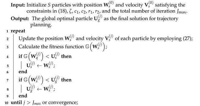
During the iteration procedure, each particle represents a single solution, which coordinates the position and velocity according to the best previous search experience and the best experience of other particles [19]. The  position and velocity of the s-th particle are updated as follows:
W s ( j + 1 ) = W s ( j ) + V s ( j + 1 ) , V s ( j + 1 ) = ζ V s ( j ) + c 1 r 1 U s ( j ) W s ( j ) + c 2 r 2 U g ( j ) W s ( j ) ,
where W s ( j + 1 ) and V s ( j + 1 ) indicate the position and velocity of particle s-th at the j-th iterations, respectively; ζ is the inertia weight;  c 1 0 and c 2 0 are two acceleration factors, respectively; r 1 and r 2 are uniformly distributed random numbers between 0 and 1, respectively; U s ( j ) denotes the best solution that the s-th particle has obtained until the j-th iteration; and  U g ( j ) denotes the best solution achieved in the whole population at the j-th iteration.
The objective utility function given in (25) can be exploited as the fitness function G W s ( j ) to optimize the flight trajectory of each airborne platform. In the end, all the particles can converge to the global optimal points via iteration and interaction with one another. The detailed steps of the PSO method for trajectory planning are shown in Algorithm 1, on the basis of which we can obtain the best flight trajectory subject to the predefined physical limitations.
Algorithm 1: The Detailed Steps of the PSO Method for Trajectory Planning in Airborne Radar Networks
Remotesensing 15 03386 i001
Stage (4) Cyclic Iteration: The flight trajectory optimization, resource allocation result, and the corresponding value of the objective function are recorded at each iterative step. Then, Stages (1)∼(3) are iterated until the gap in the acquired value of objective function between one iteration and another is smaller than a specified threshold. In the end, the smallest value of the criterion function in (21) is recorded as the final result, and the corresponding collaborative optimization results are considered as the reasonable feasible solutions.

3.5. Resource-Aware Closed-Loop Signal Processing Framework for MTT

The primary objective of the CTPRA strategy for MTT in airborne radar networks under the consideration of spectral coexistence is to optimally design the kinematic velocity, course angle, target-to-radar assignment, transmit power, dwell time, and signal effective bandwidth allocation at each instant in order to improve the tracking accuracies of multiple targets in the context of several constraints on the tolerable level of interference energy, platform kinematic limitations, and certain illumination resource budgets. In order to clearly illustrate the working mechanism, Figure 2 shows the flow chart of the joint optimization process for MTT in airborne radar networks under spectral coexistence. The multi-target state measurements obtained by all the local airborne radars are sent directly to the fusion center for further processing to acquire the optimal MTT accuracy. Due to the non-linear characteristics of the observation function in (7) and the convergence requirement, the EKF technique is adopted to track multiple targets. In the closed-loop process, the measurement of each target from the previous tracking instant is regarded as the prior knowledge for the current instant to calculate the state prediction. It can be observed from Equations (10) and (13) that the covariance matrix of measurement noise and the predicted BCRLB are both functions of the flight trajectory and transmit resource of the overall system, which have great impacts on the MTT accuracy. Then, the estimated states of multiple targets are retrieved and employed to compute the performance metric for tracking target q in the spectral coexistence environment. After that, the parameters of interest, v n , k , θ n , k , μ n , k q , P t , n , k q , T d , n , k q , and β n , k q , can be obtained by solving the CTPRA problem. The outcome is sent back to individual airborne platforms to guide trajectory planning and resource allocation and obtain new measurements for the next recursion.

4. Numerical Results

4.1. Parameter Designation

To demonstrate the effectiveness and advantages of the developed CTPRA strategy, several numerical examples are presented here. The airborne radar networks are composed of N = 6 separately deployed airborne radar nodes, which coexist with M = 2 communication systems in the same frequency band. Each airborne radar can only track one target during each tracking frame. Q = 2 targets are tracked by the radar system, whose initial states are shown in Table 1. The time interval between two consecutive tracking frames is set as Δ T = 3 s, and a sequence of L Fr = 50 data frames is utilized to support the numerical simulations. Unless otherwise specified, the tolerable level of interference energy produced by different radars in the m-th communication system is E max = 10 J. The total illumination power, dwell time, and signal bandwidth assigned to each target are P tot = 700 W , T tot = 0.1 s , and β tot = 3 MHz , respectively. In the PSO algorithm, the total number of particles is S = 20 , ζ = 1 , c 1 = 0.8 , c 2 = 0.8 , and J max = 50 . Other simulation parameters are provided in Table 2, and the initial states of multiple airborne platforms are summarized in Table 3.

4.2. Experiment 1

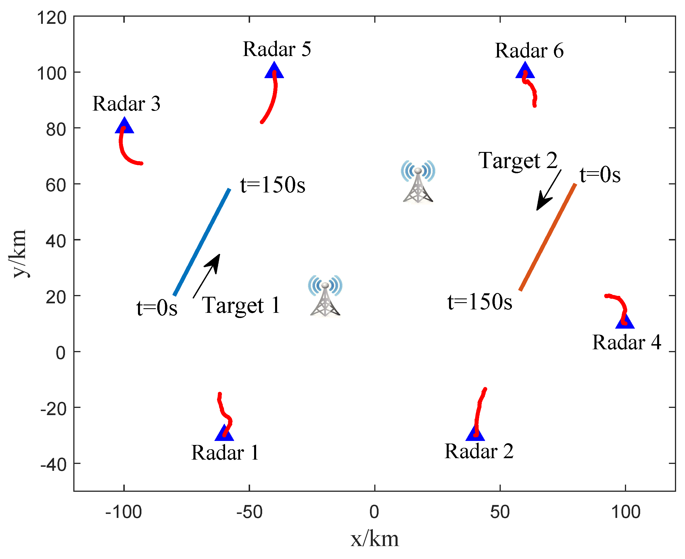
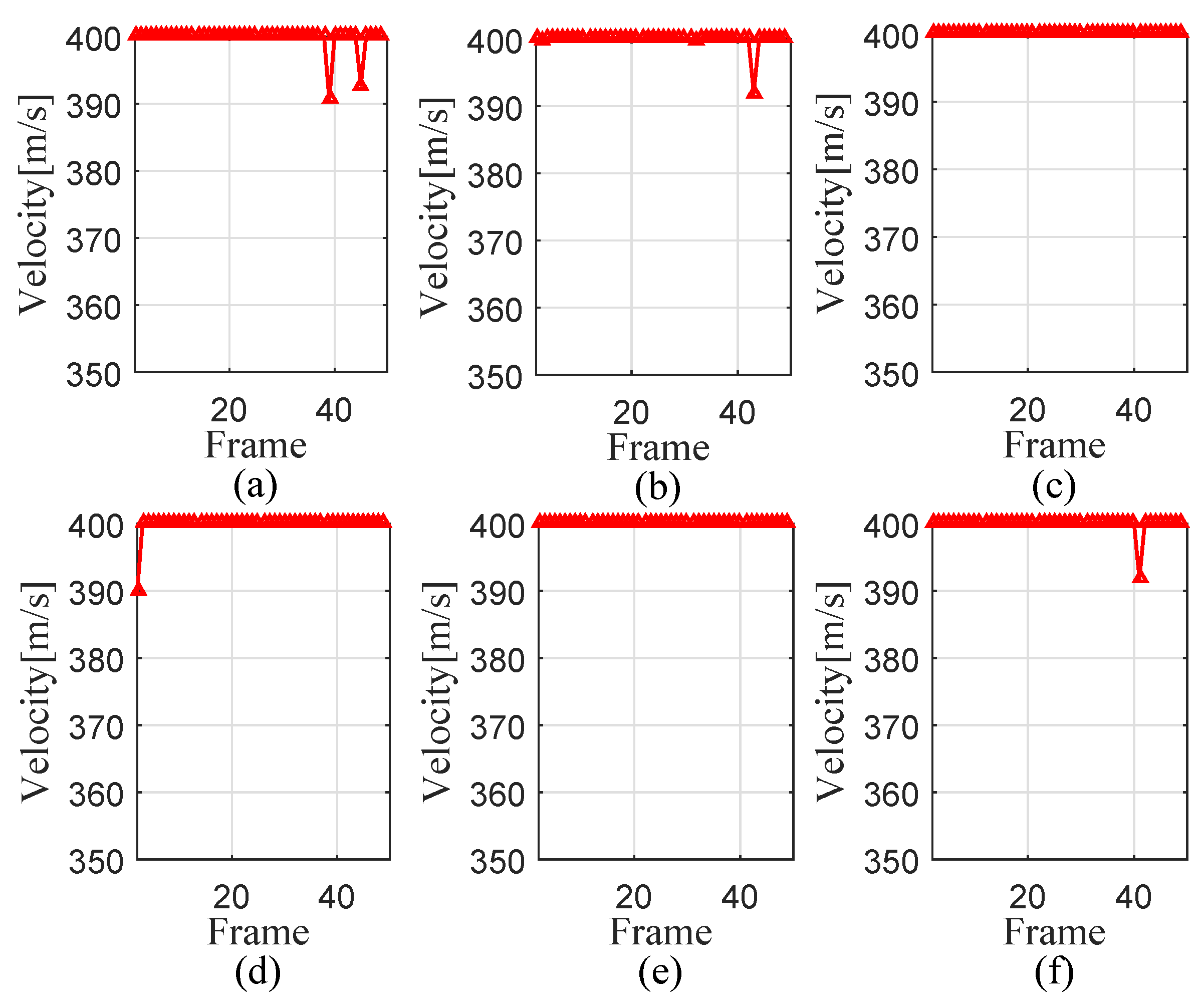
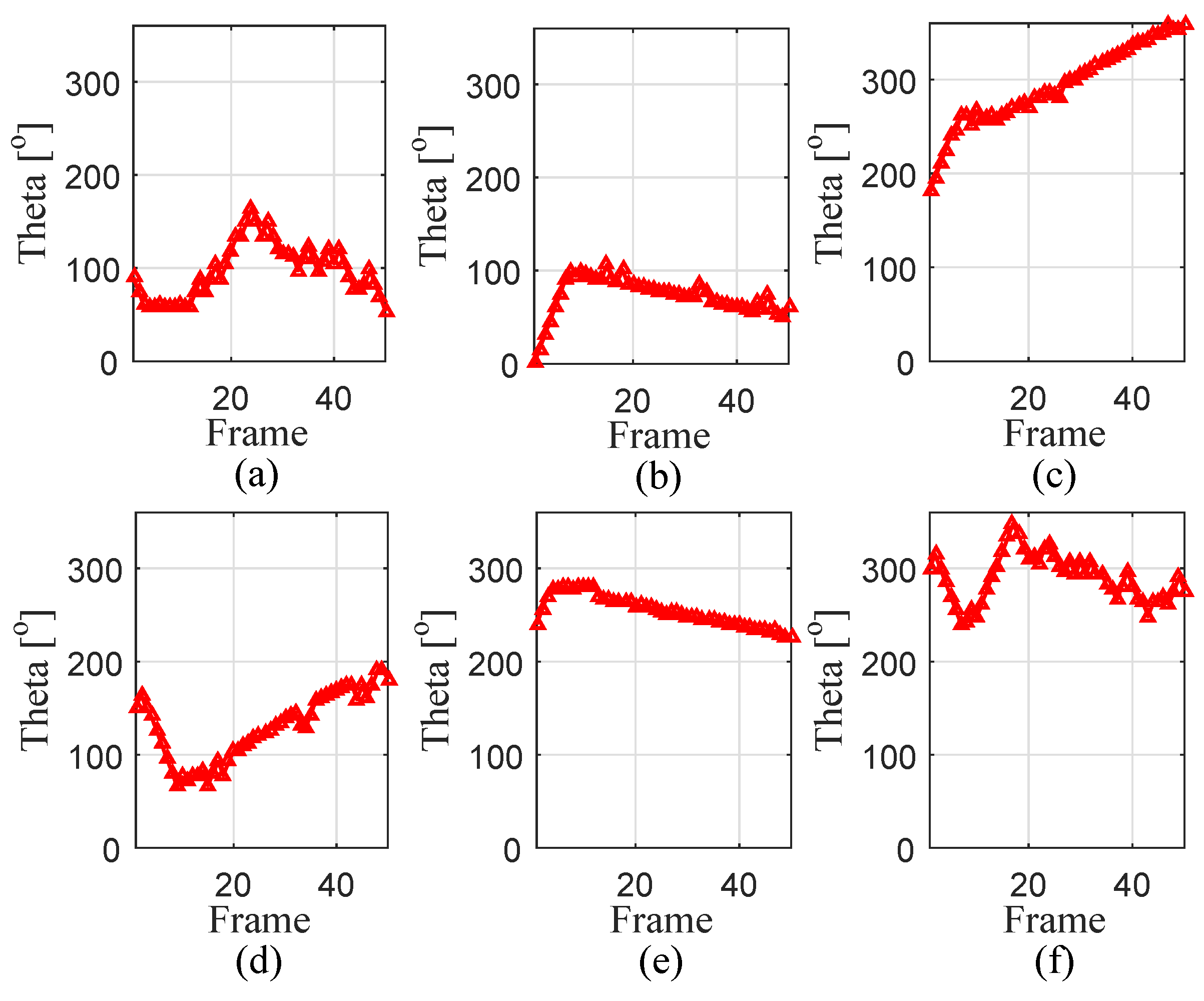
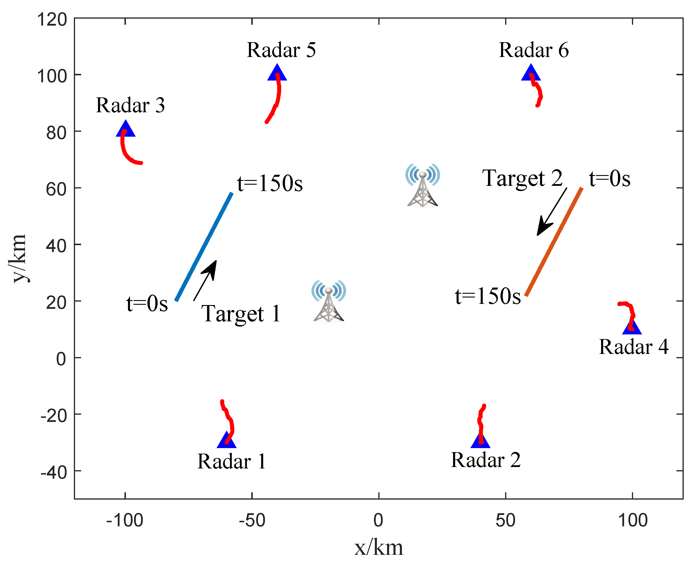
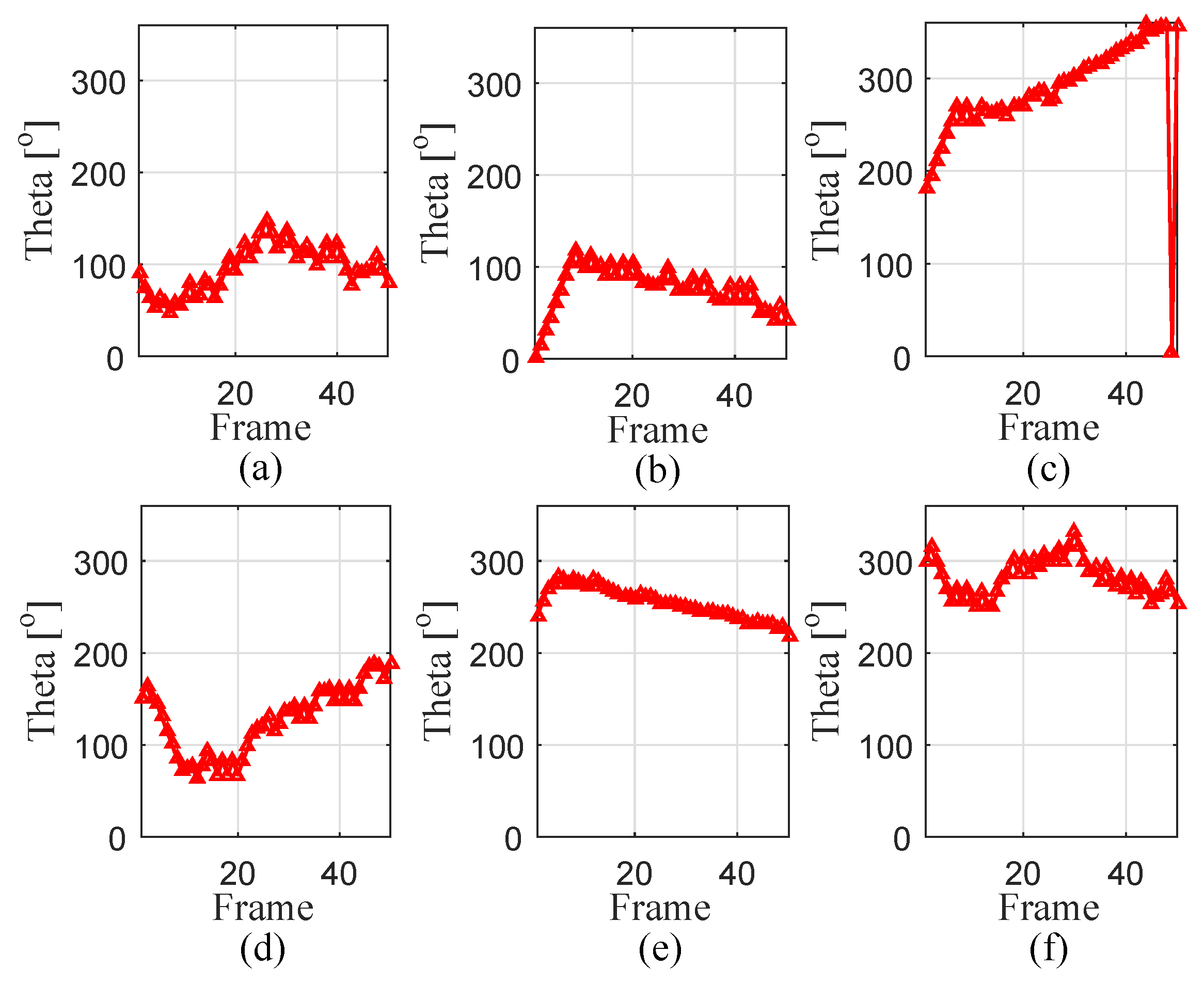
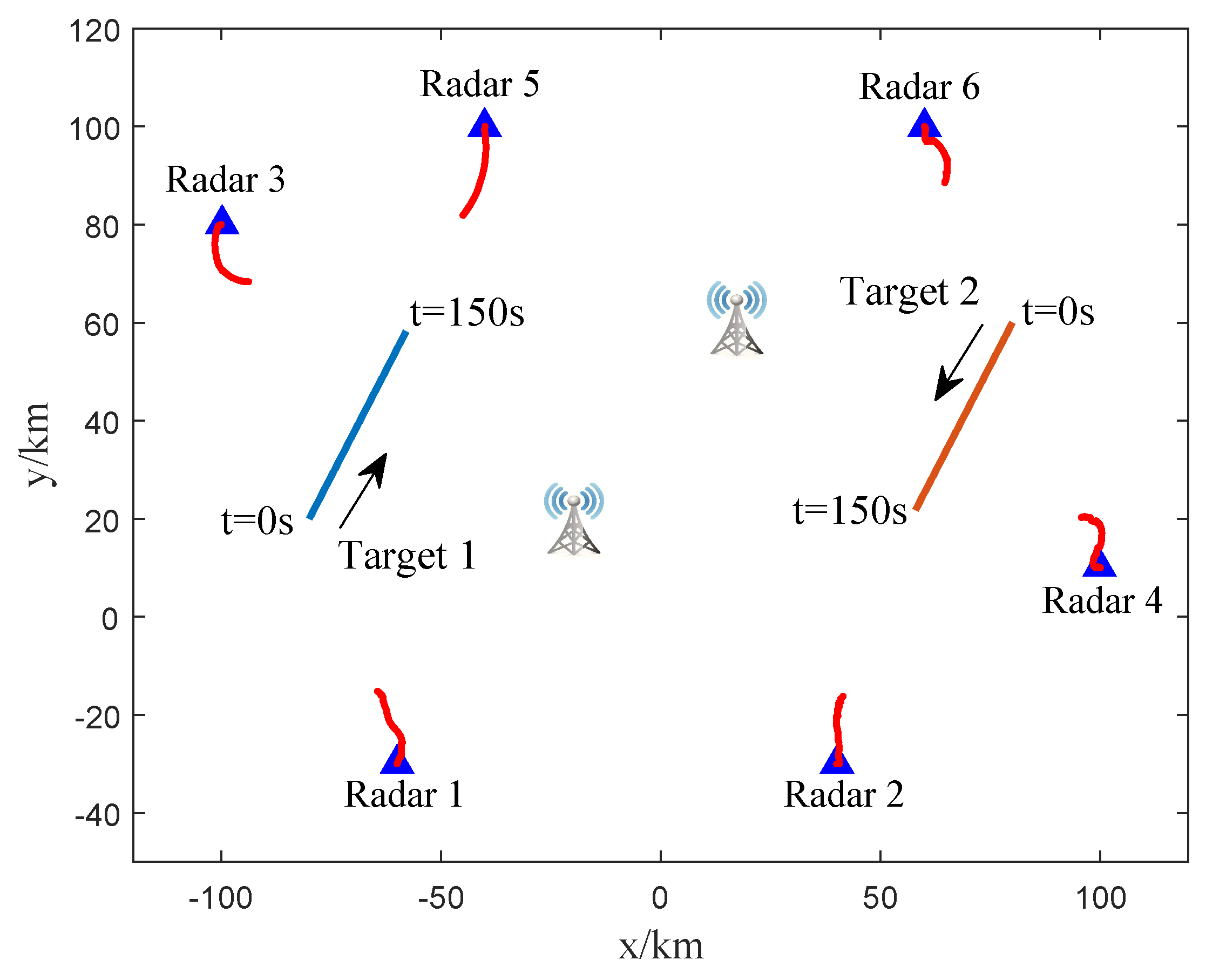
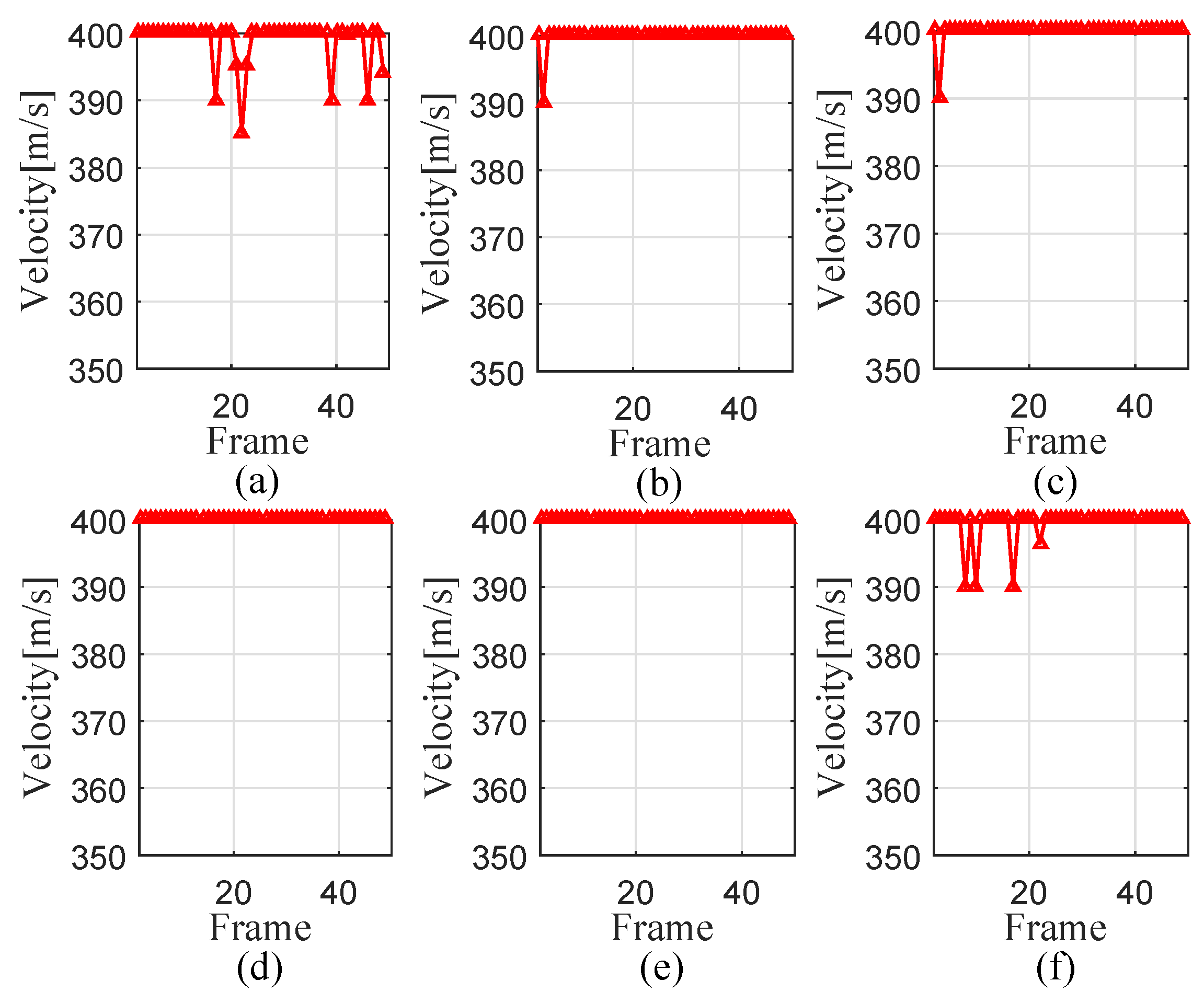
In this experiment, the RCSs of multiple targets with respect to all the airborne radars are the same, namely σ RCS , n q = 1 m 2 , which factors out the influence of target reflectivity. Figure 3 illustrates the simulated target tracking scenario, where the thick solid red lines mean the optimized trajectories of multiple airborne radar platforms. Figure 4 and Figure 5 depict the optimization results of the kinematic velocity and course angle of multiple airborne platforms, respectively, where one can notice that the planned trajectory of each airborne platform is smooth due to the physical limitations.
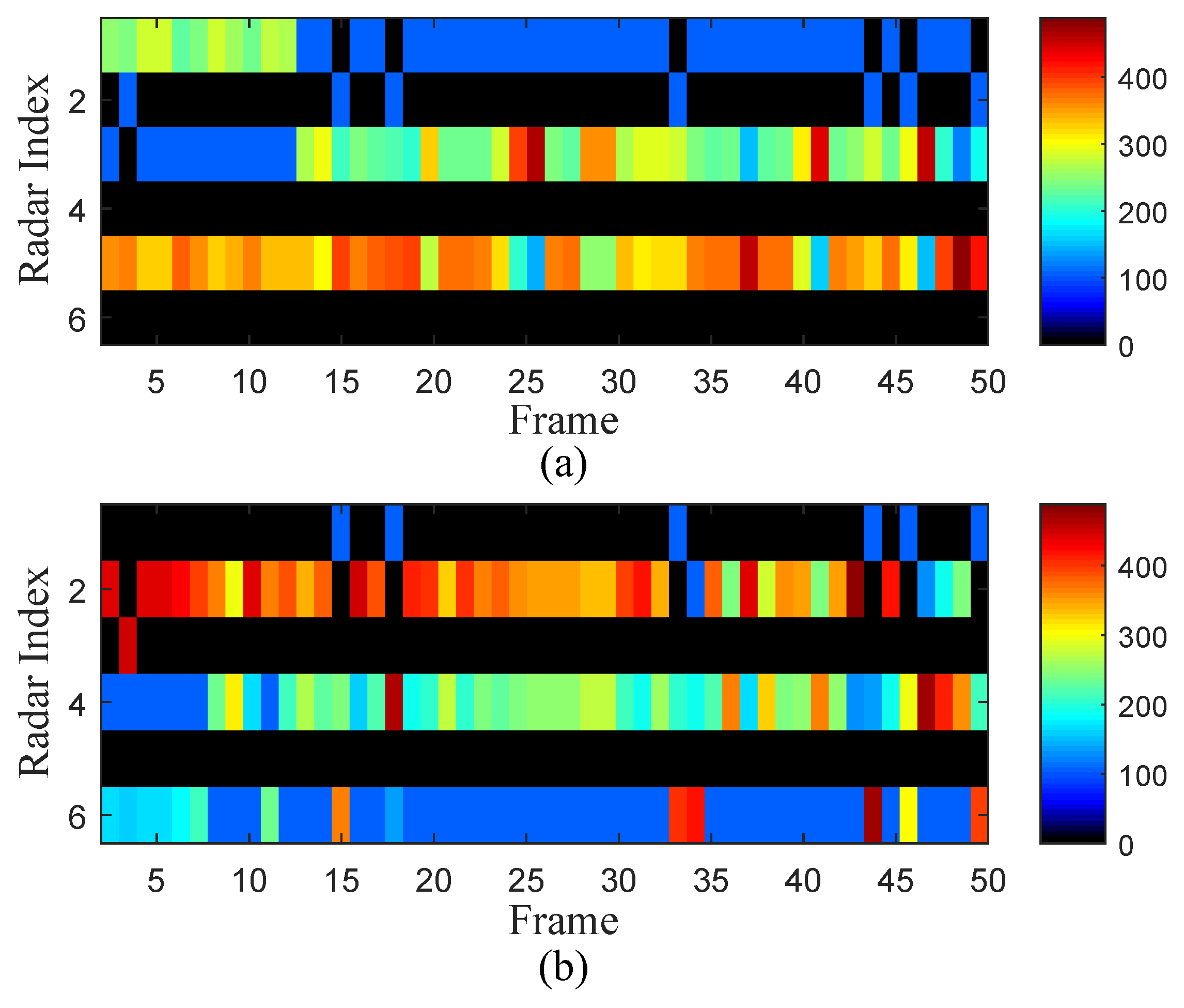
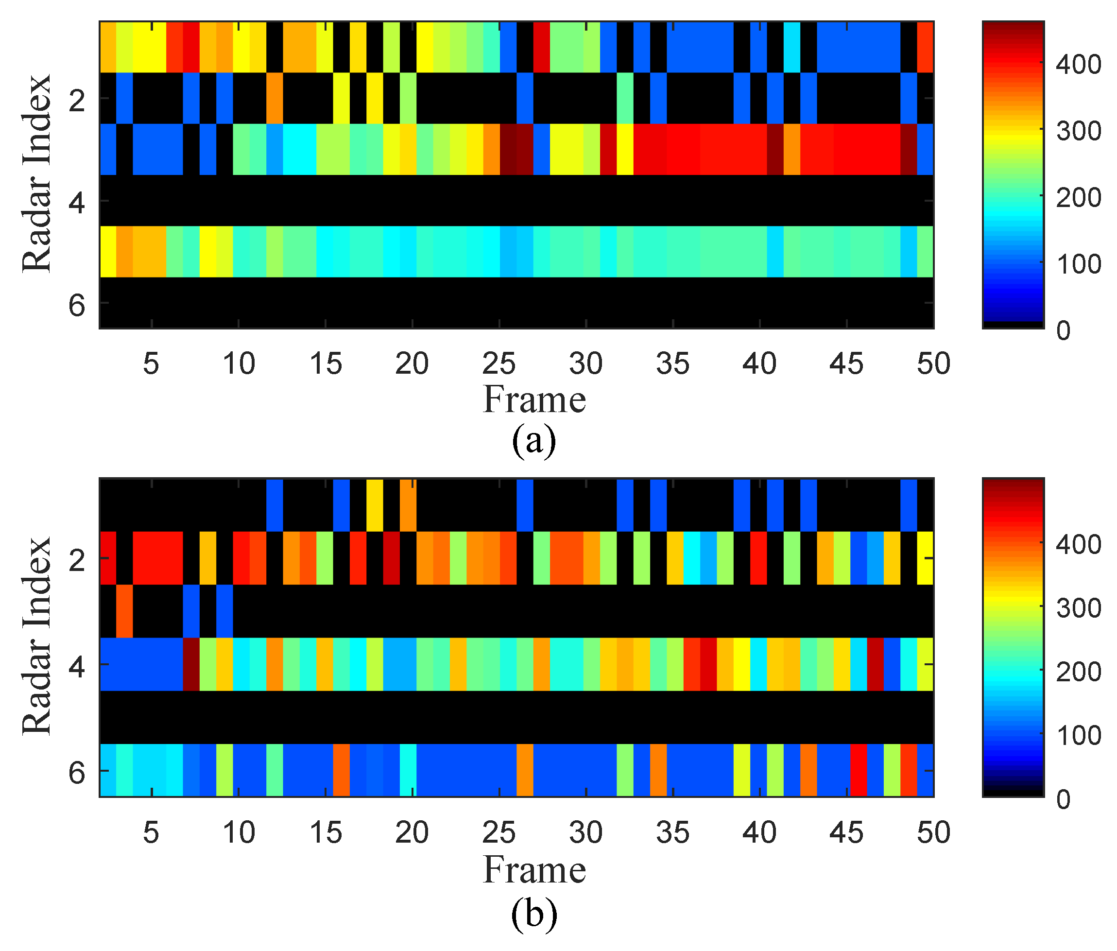
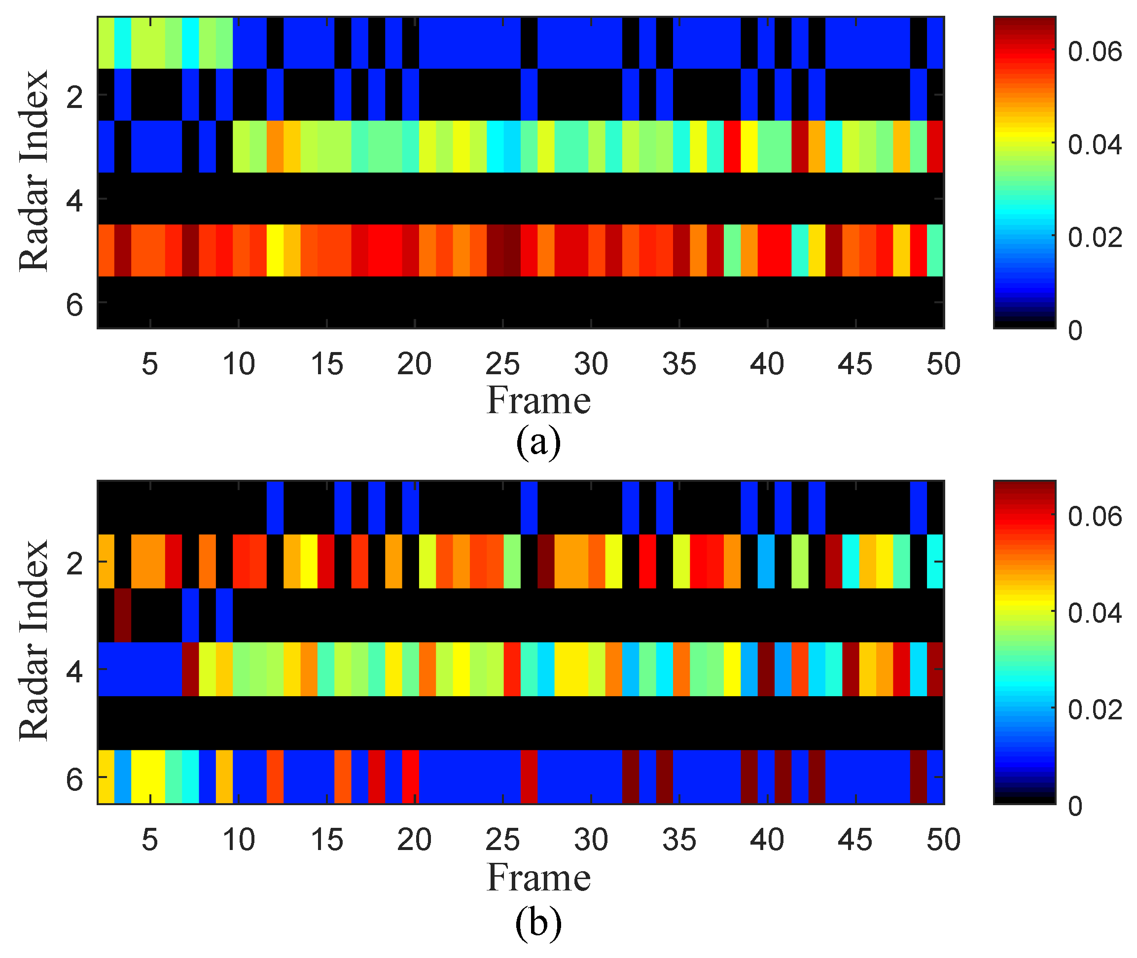
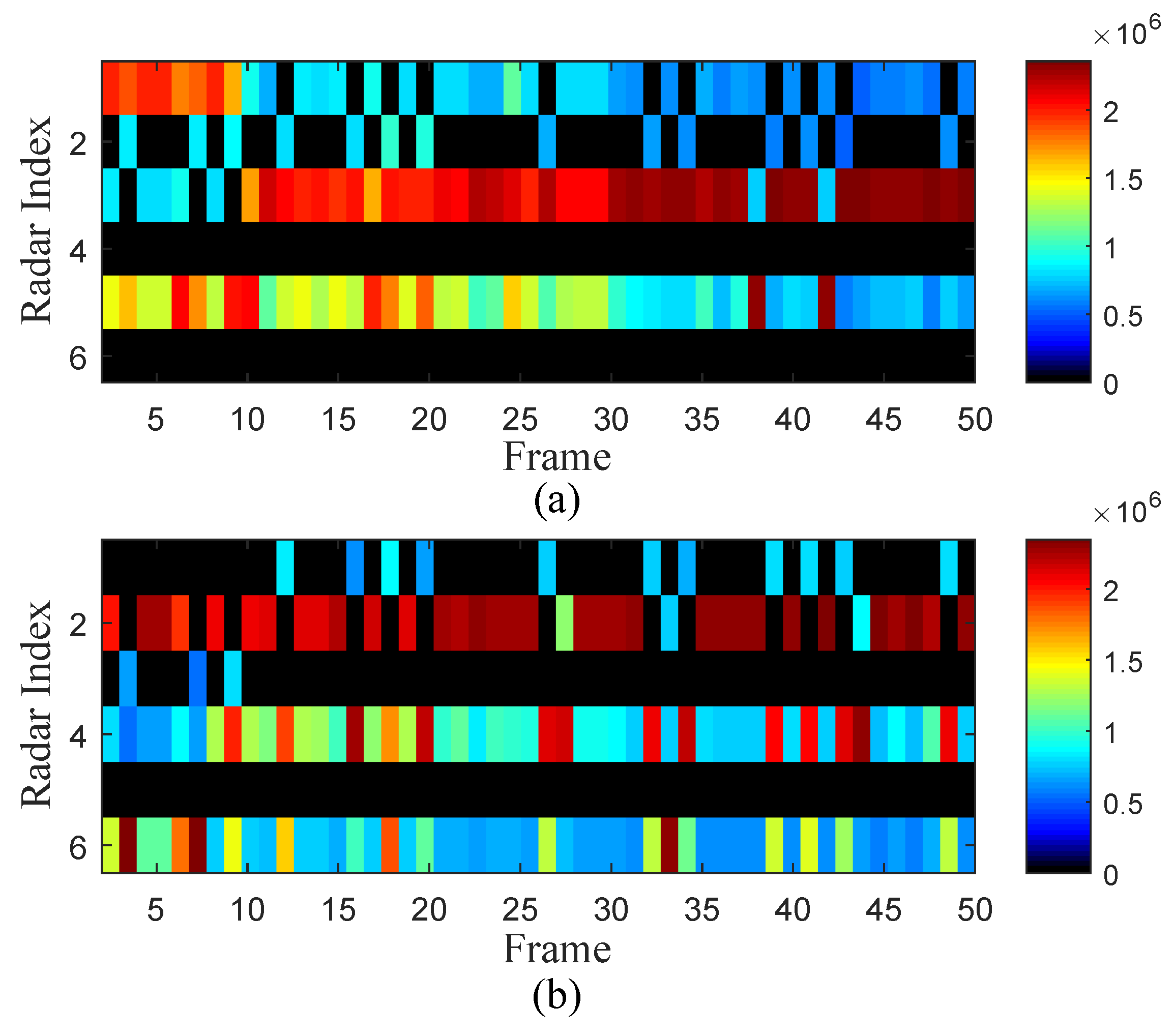
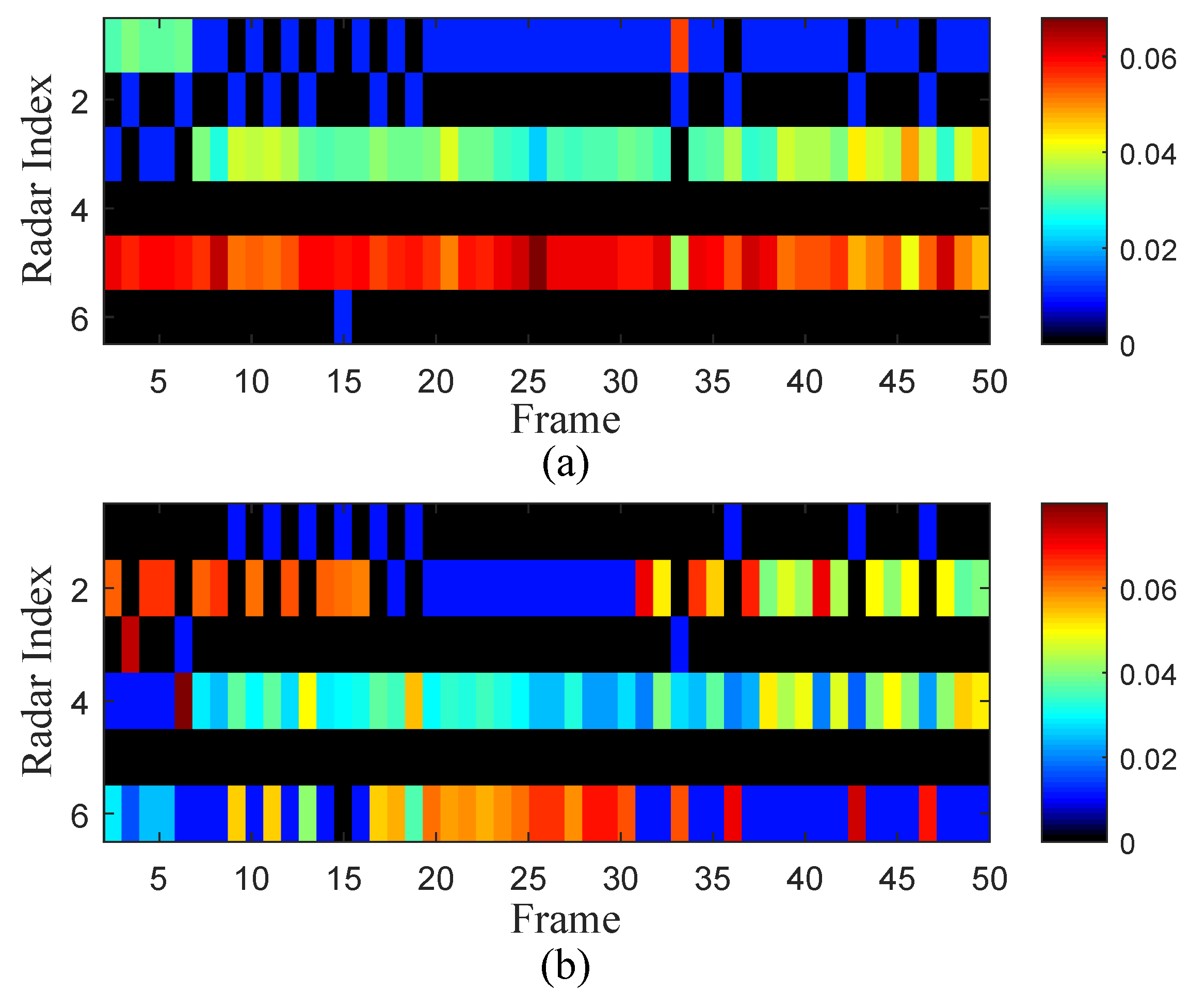
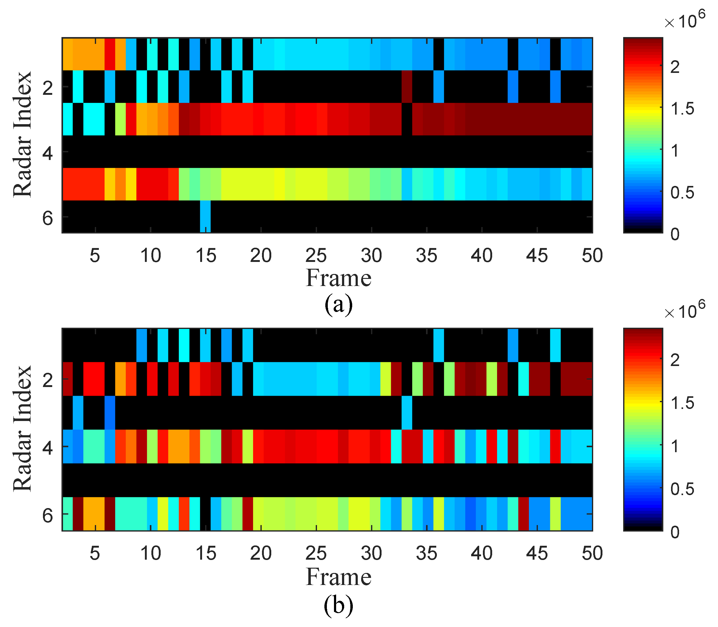
The illumination power, dwell time, and signal effective bandwidth allocation results of the developed CTPRA strategy with respect to different targets are depicted in Figure 6, Figure 7 and Figure 8, respectively, where black areas mean that μ n , k q = 0 , and other areas imply that μ n , k q = 1 , with different colors representing the value of assigned resources to the q-th target from airborne radar n. It is noteworthy that, in Figure 6, Radar 1, Radar 3, and Radar 5 are dispatched to observe Target 1, whereas the other radars are chosen to track Target 2. In addition, more transmit resources are distributed to Radar 2 and Radar 5, as the corresponding targets are flying towards them. The same can be observed for resource allocation in Figure 7 and Figure 8. Generally speaking, the results suggest that closer airborne radars with a better angular spread are more likely to be selected to track the corresponding targets. Moreover, more illumination resources are assigned to the selected airborne radar nodes with worse propagation path conditions, which leads to a better MTT performance.
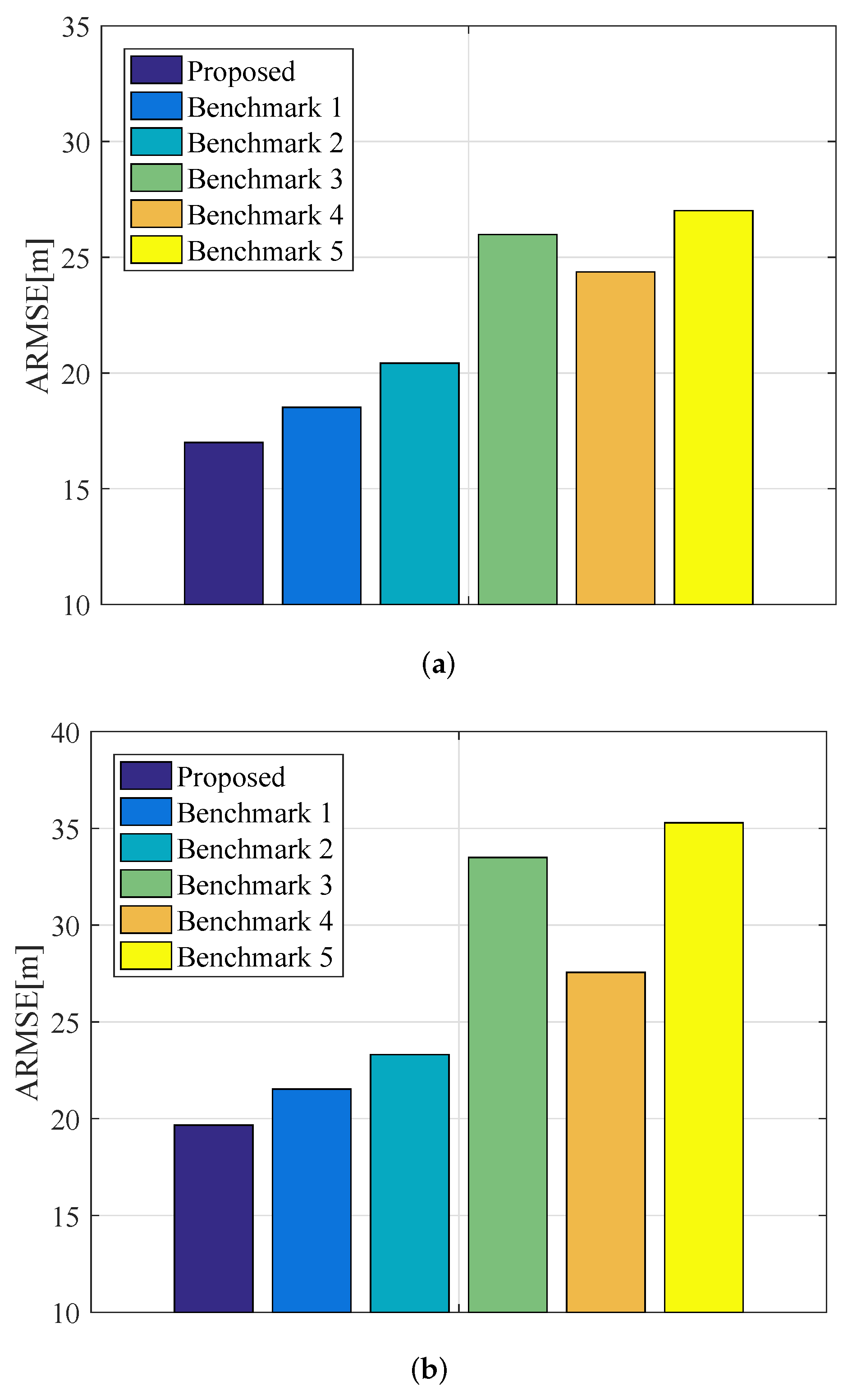
To further demonstrate the superiority of the proposed CTPRA strategy in terms of the obtained MTT accuracy, Figure 9 compares its averaged root mean square error (ARMSE) of radar networks with those of the following five benchmarks, which are obtained from 100 independent Monte-Carlo trials:
  • Benchmark 1: This benchmark jointly optimizes the kinematic velocity, course angle, radar assignment, transmit power, and dwell time of each airborne radar node by utilizing the developed four-stage-based solution technique, whereas the signal effective bandwidth of multiple airborne radars is uniformly allocated [17].
  • Benchmark 2: This benchmark adopts the developed four-stage-based solution algorithm to collaboratively coordinate the kinematic velocity, course angle, radar assignment, and transmit power of each airborne radar node, while the dwell time and signal effective bandwidth of multiple airborne radars are uniformly distributed [2].
  • Benchmark 3: In this benchmark, only the kinematic velocity, course angle, and radar assignment of each airborne platform are jointly optimized, whereas the other illumination resources are uniformly allocated to the chosen airborne radar nodes.
  • Benchmark 4: This benchmark employs the proposed four-stage-based solution methodology to solve the problem in (21), whereas the corresponding kinematic velocity and course angle are fixed to their initial values, respectively [29,30].
  • Benchmark 5: This benchmark randomly assigns the airborne radars to multiple targets. For the selected radar nodes with respect to the corresponding targets, the flight trajectory and illumination resource are optimally designed by solving the problem in (21) with the four-stage-based solution approach.
    Figure 9. Comparison of the achievable ARMSE by employing various algorithms for different targets in Experiment 1: (a) target 1; (b) target 2.
    Figure 9. Comparison of the achievable ARMSE by employing various algorithms for different targets in Experiment 1: (a) target 1; (b) target 2.
    Remotesensing 15 03386 g009
The tracking ARMSE for multiple targets at the k-th tracking instant is given as follows:
ARMSE q = 1 Q 1 M c i = 1 M c 1 L Fr k = 1 L Fr ( x k q x ^ i , k | k q ) 2 + ( y k q y ^ i , k | k q ) 2 ,
where M c is the number of Monte-Carlo trials and [ x ^ i , k | k q , y ^ i , k | k q ] represents the position estimate of target q at the i-th trial. From Figure 9, we can notice that the proposed CTPRA strategy exhibits the smallest ARMSE compared with the results obtained from other methods. This is due to the fact that the CTPRA strategy is able to collaboratively adjust the kinematic velocity, course angle, target-to-radar assignment, illumination power, dwell time, and signal effective bandwidth of the overall system to minimize the objective function in (21) for the tolerable threshold of interference energy, whereas less degrees of freedom are available for other benchmarks, which confirms the statement that the proposed scheme can effectively improve the MTT accuracy and increase the resource usage efficiency of airborne radar networks. These results indicate the superiority of the developed CTPRA strategy.

4.3. Experiment 2

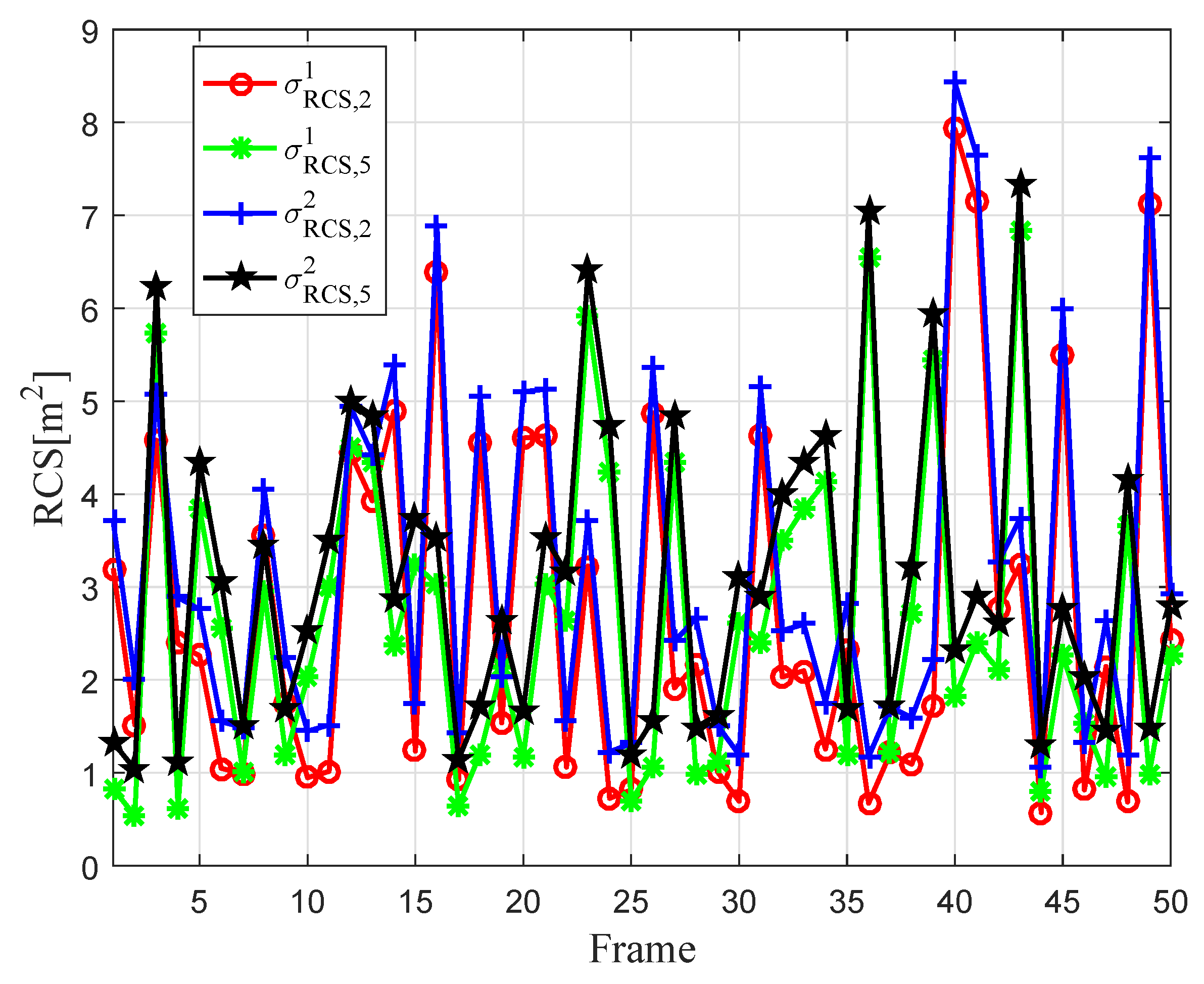
In this experiment, we reveal the impact of target reflectivity on the flight trajectory optimization and resource allocation results. Figure 10 shows the second RCS model of different targets with respect to multiple airborne radars at each tracking instant, which fluctuate according to the Swerling I model, while the other RCS parameters stay the same at 1 m 2 . The simulated target tracking scenario in Experiment 2 is depicted in Figure 11. The optimization results of the kinematic velocity and course angle of different airborne platforms in Experiment 2 are provided in Figure 12 and Figure 13, respectively, and the corresponding resource allocation results are shown in Figure 14, Figure 15 and Figure 16, which are acquired from a single Monte-Carlo simulation run. The above results are quite different from the phenomena in Experiment 1, whereas the tendencies are the same. It is implied that the CTPRA strategy can automatically select the most appropriate airborne radars to track the targets while optimizing the flight trajectories and transmit resources of those preferred radar nodes. That is to say, the airborne radars with shorter distances to the targets, better angular spread, and stronger reflectivity tend to be chosen over other nodes. Particularly, as shown in the above-mentioned figures, Radar 2 is more likely to be dispatched to illuminate Target 1 along with Radar 3 and Radar 5 due to the RCS value of Target 1 with respect to Radar 2 being much larger than 1 m 2 during most tracking frames. In addition, more probing power and dwell time resources are allocated to the dispatched airborne radars with weaker measurement conditions. Therefore, it can be concluded that the target RCS has a great impact on the trajectory planning and resource allocation of airborne radar networks.
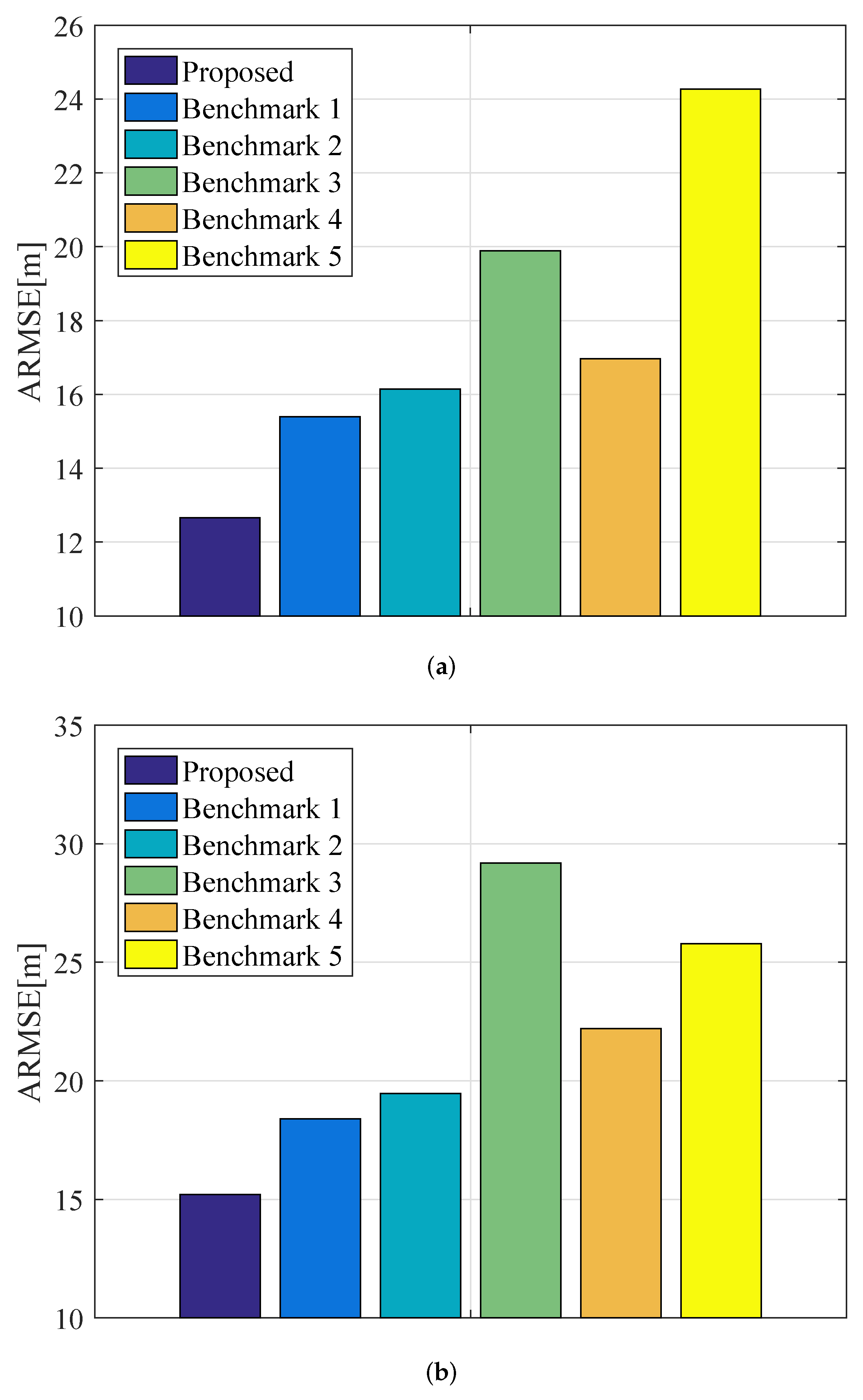
In Experiment 2, the achievable ARMSE for MTT by exploiting the proposed CTPRA strategy is also adopted as a metric to compare with the five baseline algorithms, as illustrated in Figure 17. Overall, with the specified thresholds of interference energy, platform kinematic limitations, and given resource budgets, the developed strategy can make better use of the available illumination resources of airborne radar networks to achieve an enhanced MTT accuracy.

4.4. Experiment 3

In this experiment, we examine the impact of the tolerable threshold of interference energy generated by multiple airborne radars to communication systems on the collaborative optimization results, which is set to be E max = 8 J . Figure 18 illustrates the simulated target tracking scenario. The optimization results in terms of the kinematic velocity, course angle, transmit power, dwell time, and signal effective bandwidth of each airborne radar node are shown in Figure 19, Figure 20, Figure 21, Figure 22 and Figure 23, respectively. An interesting phenomenon is that, although the radar assignment principle stays the same as before, much more probing power and dwell time resources are assigned to the selected airborne radars. The reason for this is that with the decrease in the tolerable threshold of interference energy, less illumination resources are available to track the targets at each frame, resulting in a limited MTT performance improvement.
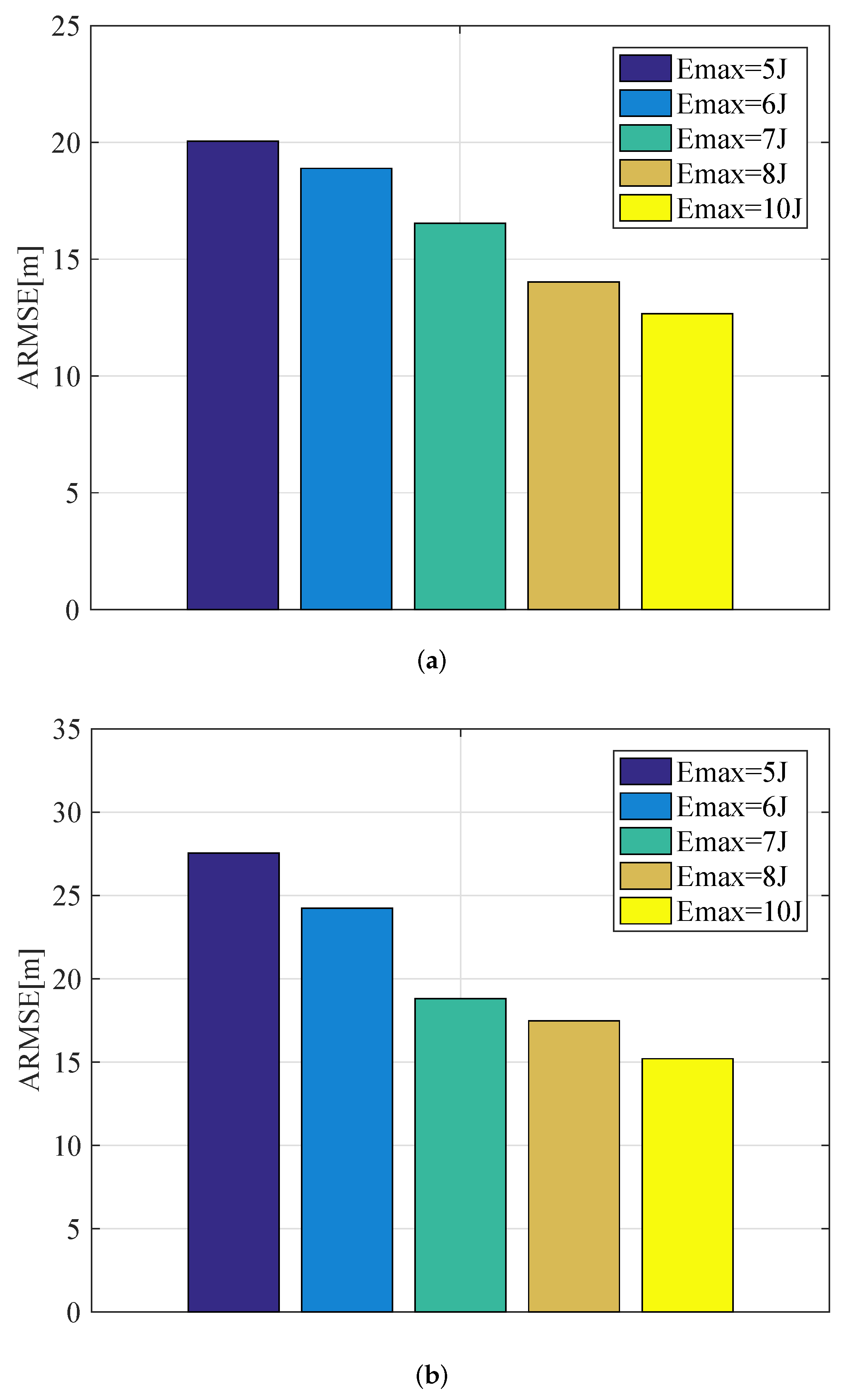
Finally, Figure 24 compares the achievable ARMSE by using the proposed CTPRA strategy with different values of E max . It is worth noting that with the increase in the tolerable level of interference energy generated by airborne radars to communication receivers, much more transmit resources can be used to improve the tracking performance of multiple targets, and thus the ARMSE for MTT can be further reduced.

5. Concluding Remarks

This article proposes a CTPRA strategy for MTT in a spectral coexistence environment employing ] airborne radar networks, whose main purpose is to adopt the optimization technique to jointly coordinate the working parameters at both the airborne platforms and the radar transmitters in order to reach a better MTT performance for the tolerable thresholds of interference energy, platform physical limitations, and overall resource constraints. The formulated mixed-integer programming, non-linear, non-convex optimization problem is solved through a comprehensive four-stage solution methodology incorporating the SDP, PSO, and cyclic minimization algorithm, where the flight trajectory, target-to-radar assignment, transmit power, dwell time, and signal effective bandwidth allocation of airborne radar networks can be controlled effectively. The numerical results demonstrate the superiority of the proposed CTPRA scheme in terms of the achieved MTT accuracy. It is noteworthy that the locations of different radars have an important impact on system performance. In the near future, we might focus on the problem of cooperative detection threshold optimization and probing resource scheduling for MTT in airborne radar networks.

Author Contributions

C.S., J.D. and Z.W. conceived and designed the experiments; C.S., J.D. and Z.W. performed the experiments; S.S. and J.Z. analyzed the data; C.S. wrote the paper; S.S. and J.Z. contributed to data analysis revision; S.S. and J.Z. contributed to English language corrections. All authors of article provided substantive comments. All authors have read and agreed to the published version of the manuscript.

Funding

This work was supported in part by the National Natural Science Foundation of China under grant 62271247, in part by the Defense Industrial Technology Development Program under grant JCKY2021210B004, and in part by the Fund of Prospective Layout of Scientific Research for NUAA (Nanjing University of Aeronautics and Astronautics).

Conflicts of Interest

The authors declare no conflict of interest.

References

  1. Zhang, W.W.; Shi, C.G.; Zhou, J.J.; Lv, R.G. Joint aperture and transmit resource allocation strategy for multitarget localization in the phased array radar network. IEEE Trans. Aerosp. Electron. Syst. 2023, 59, 1551–1565. [Google Scholar]
  2. Zhang, Y.S.; Pan, M.H.; Han, Q.H.; Long, W.J.; Yang, S.W. Joint power allocation and route planning scheme for multitarget tracking in airborne radar network under multiuncertainty. IEEE Sens. J. 2023, 23, 7705–7718. [Google Scholar] [CrossRef]
  3. Xie, M.C.; Yi, W.; Kirubarajan, T.; Kong, L.J. Joint node selection and power allocation strategy for multitarget tracking in decentralized radar networks. IEEE Trans. Signal Process. 2018, 66, 729–743. [Google Scholar] [CrossRef]
  4. Zhang, H.W.; Liu, W.J.; Shi, J.P.; Fei, T.Y.; Zong, B.F. Joint detection threshold optimization and illumination time allocation strategy for cognitive tracking in a networked radar system. IEEE Trans. Signal Process. 2022, 70, 5833–5847. [Google Scholar] [CrossRef]
  5. Yi, W.; Yuan, Y.; Kirubarajan, T.; Kong, L.J. Resource scheduling for distributed multi-target tracking in netted colocated MIMO radar systems. IEEE Trans. Signal Process. 2020, 68, 1602–1617. [Google Scholar] [CrossRef]
  6. Sun, H.; Li, M.; Zuo, L.; Zhang, P. Joint radar scheduling and beampattern design for multitarget tracking in netted colocated MIMO radar systems. IEEE Signal Process. Lett. 2021, 28, 1863–1867. [Google Scholar] [CrossRef]
  7. Dai, J.H.; Yan, J.K.; Lv, J.D.; Ma, L.; Pu, W.Q.; Liu, H.W.; Greco, M. Composed resource optimization for multitarget tracking in active and passive radar network. IEEE Trans. Geosci. Remote Sens. 2022, 60, 1–15. [Google Scholar] [CrossRef]
  8. Du, Y.; Liao, K.F.; Ouyang, S.; Li, J.J.; Huang, G.J. Time and aperture resource allocation strategy for multitarget ISAR imaging in a radar network. IEEE Sens. J. 2020, 20, 3196–3206. [Google Scholar] [CrossRef]
  9. Wang, D.; Zhang, Q.; Luo, Y.; Liu, X.W.; Ni, J.C.; Su, L.H. Joint optimization of time and aperture resource allocation strategy for multi-target ISAR imaging in radar sensor network. IEEE Sens. J. 2021, 21, 19570–19581. [Google Scholar] [CrossRef]
  10. Su, Y.; Cheng, T.; He, Z.S. Joint resource and detection threshold optimization for maneuvering targets tracking in colocated MIMO radar network. IEEE Trans. Aerosp. Electron. Syst. 2023. [Google Scholar] [CrossRef]
  11. Yan, J.K.; Pu, W.Q.; Zhou, S.H.; Liu, H.W.; Bao, Z. Collaborative detection and power allocation framework for target tracking in multiple radar system. Inf. Fusion 2020, 55, 173–183. [Google Scholar] [CrossRef]
  12. Li, X.; Cheng, T.; Su, Y.; Peng, H. Joint time-space resource allocation and waveform selection for the collocated MIMO radar in multiple targets tracking. Signal Process. 2020, 176, 107650. [Google Scholar] [CrossRef]
  13. Lawrence, D.E. Low probability of intercept antenna array beamforming. IEEE Trans. Antennas Propag. 2010, 58, 2858–2865. [Google Scholar] [CrossRef]
  14. Govoni, M.A.; Li, H.B.; Kosinski, J.A. Low probability of intercept of an advanced noise radar waveform with linear-FM. IEEE Trans. Aerosp. Electron. Syst. 2013, 49, 1351–1356. [Google Scholar]
  15. Shi, C.G.; Wang, F.; Sellathurai, M.; Zhou, J.J.; Salous, S. Power minimization-based robust OFDM radar waveform design for radar and communication systems in coexistence. IEEE Trans. Signal Process. 2018, 66, 1316–1330. [Google Scholar] [CrossRef] [Green Version]
  16. Zhou, C.W.; Gu, Y.J.; He, S.B.; Shi, Z.G. A robust and efficient algorithm for coprime array adaptive beamforming. IEEE Trans. Veh. Technol. 2018, 67, 1099–1112. [Google Scholar] [CrossRef]
  17. Shi, C.G.; Dai, X.R.; Wang, Y.J.; Zhou, J.J.; Salous, S. Joint route optimization and multidimensional resource management scheme for airborne radar network in target tracking application. IEEE Syst. J. 2022, 16, 6669–6680. [Google Scholar] [CrossRef]
  18. Yuan, Y.; Yi, W.; Hoseinnezhad, R.; Varshney, P.K. Robust power allocation for resource-aware multi-target tracking with colocated MIMO radars. IEEE Trans. Signal Process. 2021, 69, 443–458. [Google Scholar] [CrossRef]
  19. Shi, C.G.; Wang, Y.J.; Salous, S.; Zhou, J.J.; Yan, J.K. Joint transmit resource management and waveform selection strategy for target tracking in distributed phased array radar network. IEEE Trans. Aerosp. Electron. Syst. 2022, 58, 2762–2778. [Google Scholar] [CrossRef]
  20. Su, Y.; Cheng, T.; He, Z.S.; Li, X. Joint waveform control and resource optimization for maneuvering targets tracking in netted colocated MIMO radar systems. IEEE Syst. J. 2022, 16, 3960–3971. [Google Scholar] [CrossRef]
  21. Shi, Y.C.; Jiu, B.; Yan, J.K.; Liu, H.W.; Li, K. Data-driven simultaneous multibeam power allocation: When multiple targets tracking meets deep reinforcement learning. IEEE Syst. J. 2021, 15, 1264–1274. [Google Scholar] [CrossRef]
  22. Deligiannis, A.; Panoui, A.; Lambotharan, S.; Chambers, J.A. Game-theoretic power allocation and the Nash equilibrium analysis for a multistatic MIMO radar network. IEEE Trans. Signal Process. 2017, 65, 6397–6408. [Google Scholar] [CrossRef] [Green Version]
  23. Yan, J.K.; Pu, W.Q.; Liu, H.W.; Jiu, B.; Bao, Z. Robust chance constrained power allocation scheme for multiple target localization in colocated MIMO radar system. IEEE Trans. Signal Process. 2018, 66, 3946–3957. [Google Scholar] [CrossRef]
  24. Shi, C.G.; Ding, L.T.; Wang, F.; Salous, S.; Zhou, J.J. Joint target assignment and resource optimization framework for multitarget tracking in phased array radar network. IEEE Syst. J. 2021, 15, 4379–4390. [Google Scholar] [CrossRef]
  25. Qian, J.H.; Lops, M.; Zheng, L.; Wang, X.D.; He, Z.S. Joint system design for coexistence of MIMO radar and communication. IEEE Trans. Signal Process. 2018, 66, 3504–3519. [Google Scholar] [CrossRef]
  26. Qian, J.H.; Venturino, L.; Lops, M.; Wang, X.D. Radar and communication spectral coexistence in range-dependent interference. IEEE Trans. Signal Process. 2021, 69, 5891–5906. [Google Scholar] [CrossRef]
  27. Bica, M.; Koivunen, V. Radar waveform optimization for target parameter estimation in cooperative radar-communications systems. IEEE Trans. Aerosp. Electron. Syst. 2019, 55, 2314–2326. [Google Scholar] [CrossRef] [Green Version]
  28. Wang, F.Z.; Li, H.B. Power allocation for coexisting multicarrier radar and communication systems in cluttered environment. IEEE Trans. Signal Process. 2021, 69, 1603–1613. [Google Scholar] [CrossRef]
  29. Lu, Y.X.; He, Z.S.; Liu, S.L.; Sun, G.H. Communication-awareness joint beams and power allocation scheme of radar network for manoeuvring targets tracking. IET Radar Sonar Navig. 2020, 14, 207–215. [Google Scholar] [CrossRef]
  30. Su, Y.; Cheng, Z.Y.; He, Z.S.; Deng, M.L. Communication-awareness adaptive resource scheduling strategy for multiple target tracking in a multiple radar system. IET Signal Process. 2022, 16, 750–761. [Google Scholar] [CrossRef]
  31. Wu, L.L.; Mishra, K.V.; Shankar, M.R.B.; Ottersten, B. Resource allocation in heterogeneously-distributed joint radar-communication under asynchronous Bayesian tracking framework. IEEE J. Sel. Areas Commun. 2022, 40, 2026–2042. [Google Scholar] [CrossRef]
  32. Boyd, S.P.; Vandenberghe, L. Convex Optimization; Cambridge University Press: Cambridge, UK, 2004. [Google Scholar]
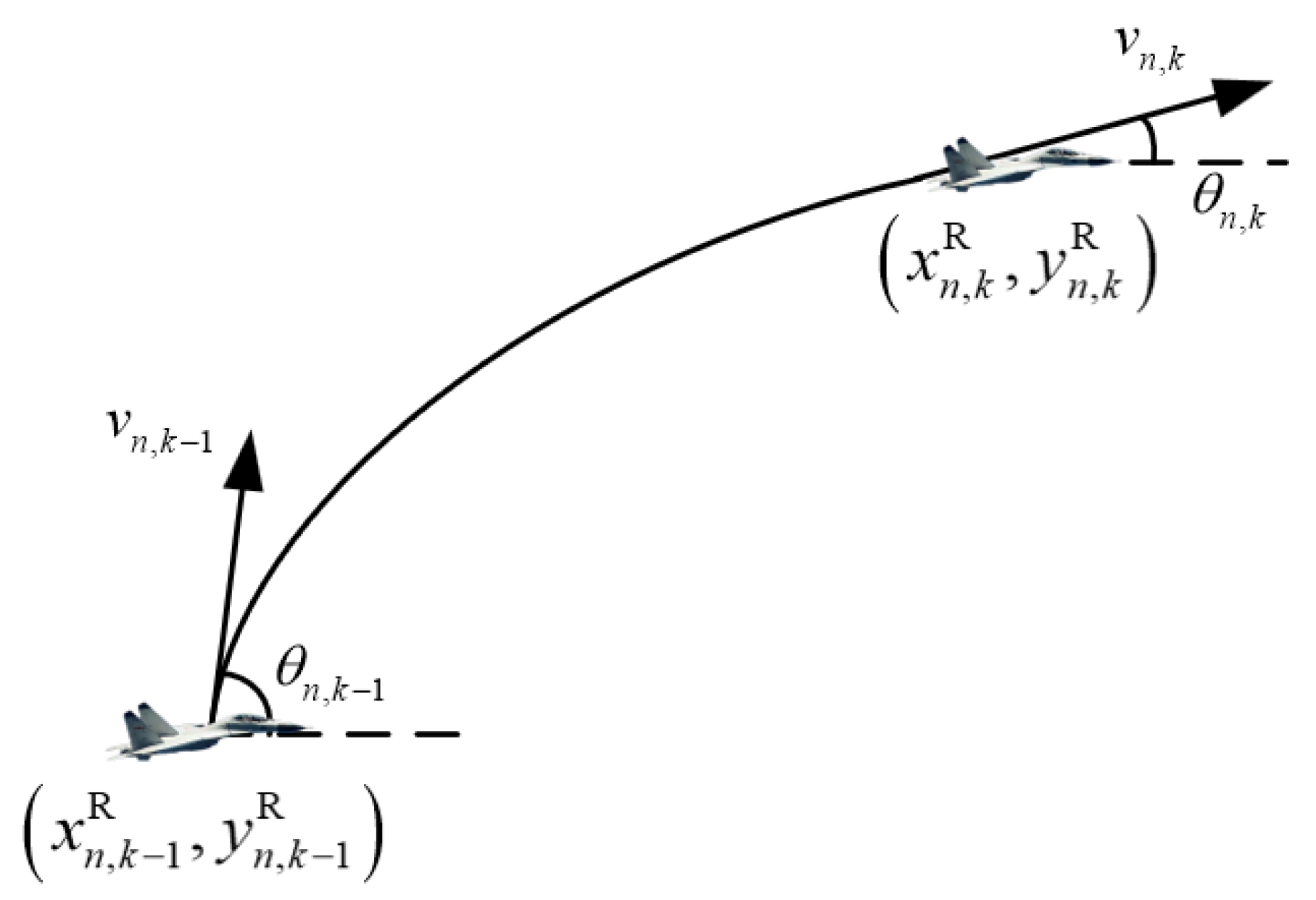
Figure 1. The kinematic model of an airborne radar platform.
Remotesensing 15 03386 g001
Figure 2. General schematics of the closed-loop process of CTPRA for MTT in airborne radar networks under spectral coexistence.
Remotesensing 15 03386 g002
Figure 3. Simulated tracking scenario in Experiment 1.
Remotesensing 15 03386 g003
Figure 4. The kinematic velocity optimization results of the CTPRA strategy in Experiment 1: (a) airborne platform 1; (b) airborne platform 2; (c) airborne platform 3; (d) airborne platform 4; (e) airborne platform 5; (f) airborne platform 6.
Remotesensing 15 03386 g004
Figure 5. The course angle optimization results of the CTPRA strategy in Experiment 1: (a) airborne platform 1; (b) airborne platform 2; (c) airborne platform 3; (d) airborne platform 4; (e) airborne platform 5; (f) airborne platform 6.
Remotesensing 15 03386 g005
Figure 6. Transmit power allocation results of the CTPRA strategy with respect to different targets in Experiment 1: (a) target 1; (b) target 2.
Remotesensing 15 03386 g006
Figure 7. Dwell time allocation results of the CTPRA strategy with respect to different targets in Experiment 1: (a) target 1; (b) target 2.
Remotesensing 15 03386 g007
Figure 8. Signal effective bandwidth allocation results of the CTPRA strategy with respect to different targets in Experiment 1: (a) target 1; (b) target 2.
Remotesensing 15 03386 g008
Figure 10. The second RCS model of the targets with respect to multiple airborne radars at each tracking frame.
Remotesensing 15 03386 g010
Figure 11. Simulated tracking scenario in Experiment 2.
Remotesensing 15 03386 g011
Figure 12. The kinematic velocity optimization results of the CTPRA strategy in Experiment 2: (a) airborne platform 1; (b) airborne platform 2; (c) airborne platform 3; (d) airborne platform 4; (e) airborne platform 5; (f) airborne platform 6.
Remotesensing 15 03386 g012
Figure 13. The course angle optimization results of the CTPRA strategy in Experiment 2: (a) airborne platform 1; (b) airborne platform 2; (c) airborne platform 3; (d) airborne platform 4; (e) airborne platform 5; (f) airborne platform 6.
Remotesensing 15 03386 g013
Figure 14. Transmit power allocation results of the CTPRA strategy with respect to different targets in Experiment 2: (a) target 1; (b) target 2.
Remotesensing 15 03386 g014
Figure 15. Dwell time allocation results of the CTPRA strategy with respect to different targets in Experiment 2: (a) target 1; (b) target 2.
Remotesensing 15 03386 g015
Figure 16. Signal effective bandwidth allocation results of the CTPRA strategy with respect to different targets in Experiment 2: (a) target 1; (b) target 2.
Remotesensing 15 03386 g016
Figure 17. Comparison of the achievable ARMSE by employing various algorithms for different targets in Experiment 2: (a) target 1; (b) target 2.
Remotesensing 15 03386 g017
Figure 18. Simulated tracking scenario in Experiment 3.
Remotesensing 15 03386 g018
Figure 19. The kinematic velocity optimization results of the CTPRA strategy in Experiment 3: (a) airborne platform 1; (b) airborne platform 2; (c) airborne platform 3; (d) airborne platform 4; (e) airborne platform 5; (f) airborne platform 6.
Remotesensing 15 03386 g019
Figure 20. The course angle optimization results of the CTPRA strategy in Experiment 3: (a) airborne platform 1; (b) airborne platform 2; (c) airborne platform 3; (d) airborne platform 4; (e) airborne platform 5; (f) airborne platform 6.
Remotesensing 15 03386 g020
Figure 21. Transmit power allocation results of the CTPRA strategy with respect to different targets in Experiment 3: (a) target 1; (b) target 2.
Remotesensing 15 03386 g021
Figure 22. Dwell time allocation results of the CTPRA strategy with respect to different targets in Experiment 3: (a) target 1; (b) target 2.
Remotesensing 15 03386 g022
Figure 23. Signal effective bandwidth allocation results of the CTPRA strategy with respect to different targets in Experiment 3: (a) target 1; (b) target 2.
Remotesensing 15 03386 g023
Figure 24. Comparison of the achievable ARMSE by employing the CTPRA strategy with different values of E max in Experiment 3: (a) target 1; (b) target 2.
Remotesensing 15 03386 g024
Table 1. Initial States of Multiple Targets.
IndexInitial PositionInitial Velocity
1 [ 80 , 20 ] km [ 150 , 260 ] m / s
2 [ 80 , 60 ] km [ 150 , 260 ] m / s
Table 2. Simulation Parameters.
SymbolValueSymbolValue
v max ¯ 400 m / s v min ¯ 300 m / s
β max ¯ 15 ° N max 3
P max ¯ 600 W P min ¯ 100 W
T max ¯ 0.08 s T min ¯ 0.01 s
β max ¯ 2.4 MHz β min ¯ 0.6 MHz
Table 3. Initial States of Multiple Airborne Platforms.
IndexInitial PositionInitial VelocityInitial Course Angle
1 [ 60 , 30 ] km 400 m / s 90 °
2 [ 40 , 30 ] km 400 m / s 0 °
3 [ 100 , 80 ] km 400 m / s 60 °
4 [ 100 , 10 ] km 400 m / s 150 °
5 [ 40 , 100 ] km 400 m / s 240 °
6 [ 60 , 100 ] km 400 m / s 300 °
Disclaimer/Publisher’s Note: The statements, opinions and data contained in all publications are solely those of the individual author(s) and contributor(s) and not of MDPI and/or the editor(s). MDPI and/or the editor(s) disclaim responsibility for any injury to people or property resulting from any ideas, methods, instructions or products referred to in the content.