3.1. Dublin Residential Areas
For the residential areas, we chose locations where various types of LPS lighting dominated. This is because these older units have the widest distribution of light, and so the largest proportion of direct to diffuse emission, with up to 10% of the lamp output being directly emitted above the horizontal for LPS 55 W prismatic lens units [
9]. Our aim was also to model locations which can be readily compared with spacecraft data, and the relatively monochromatic light provided by LPS units facilitates calculations to convert from lumens to watts, which are the more standard units for earth observation (see also
Section 3.7).
We used colour imagery obtained from the International Space Station (ISS) in conjunction with our public lighting databases to identify contiguous areas which contained LPS lighting with similar wattage predominantly throughout, either 55 W, 90 W, or 135 W, depending on location. In a search of the NASA archive we located image ISS045-E-170140 from 2015, which is roughly contemporaneous with our lighting database and elevation data. We also used this image to identify areas which were uncontaminated by neighbouring lighting, such as commercial or architectural floodlighting. In this regard, the ability to determine both intensity and colour from the ISS camera data proved useful in distinguishing useful areas, as these locations are easily distinguishable in the imagery and—for the wattages used in our study—at intensities where the camera response is linear. Our chosen areas lie at distances ranging from two to nine kilometres from the centre of Dublin, with the bulk being beyond four kilometres.
The representative residential areas chosen were sufficiently large to contain tens to just over one hundred lanterns (see
Table 2). In terms of the general environment, residential streets had roadways 6 to 8 m wide, with tree-lined pavements and an average building height (ABH)—defined as height above roadway of 3 m or more, to exclude walls, shrubs, etc.—of 7.1 m, with a standard deviation (SDBH) of 2.36 m. The residential public lighting lanterns were typically located at 6 to 7 m above the ground, while higher wattage lighting was located at 8 to 10 m above the roadway on busier roads which were up to 11 m wide. The geometry of the individual areas varied from housing estates to single streets and are classed as discontinuous urban fabric in the EU Corine 2018 land cover database. Modelling of the areas to produce azimuthally averaged emission functions followed the procedure outlined in Paper One, and we refer the reader to that paper for details. A point to note for all results reported in this work is that, although the lantern photometry only provides data for a discrete set of angles, we have fitted a sixth-order polynomial to the calculated values in order to produce a smooth curve for both display and also numerical integration purposes.
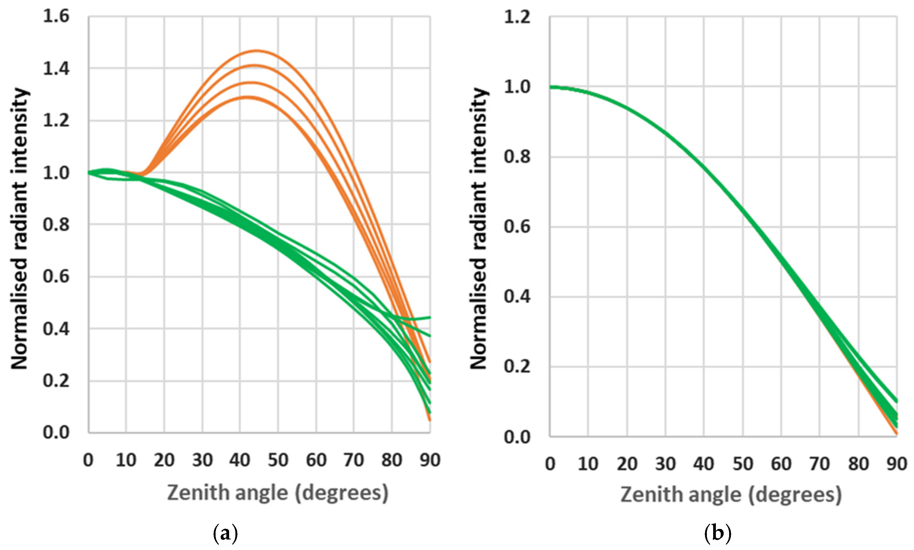
The results presented in
Figure 1 show the azimuthally averaged radiant intensity emission functions. Each curve is normalised to its zenithal value so that the relative behaviour of the curves can be readily seen with the data falling into two broad categories, dependent on the nature of the lantern. The curves with the highest emission correspond to locations where there is a large component of emission to intermediate angles from 55 W LPS lanterns with prism lenses. The local environment is a secondary effect which generates the spread of results within both broad categories, though the direct emission from the 55 W lanterns exaggerates this behaviour.
To illustrate the importance of direct emission in these cases, we show in
Figure 1b the reflected component only, which illustrates that there is little difference between any of the areas in terms of environmental modification of emission. As a side note, this plot also indicates the expected behaviour when older prismatic lanterns are replaced with more modern units with better light control, where less light is emitted in directions where it misses the ground. The contribution of this light can also be inferred from
Table 2, where the integrated light ratio is shown under the column “Direct/Total”.
3.2. Irish Towns
We also modelled entire rural Irish towns, comprising the towns in the Cork area introduced in Paper One supplemented by larger towns. These towns were selected on the basis of available digital elevation models, whose details are presented in
Table 2. As in the case of the residential areas, Irish towns are generally low- to mid-rise in height with a mix of street widths: for market towns, there is a wider street or square, but narrower streets elsewhere. For these locations, the lighting is again predominantly of LPS and HPS type, though not as uniform in wattage as the Dublin residential areas, which were chosen to be near uniform in character. Additionally, when moving to these larger towns, there may be a range of road sizes and also a larger contribution from commercial lighting. The current work does not intend to provide a complete model for these towns in terms of all lighting components, but rather to test our model over larger areas with more numerous lights. The intended goal is to determine whether there are any commonalities in terms of emission function for this range of locations and to study how differences in the nature of the wider urban environment may influence the emission of light into the surrounding countryside and to space.
The largest town modelled, Tralee in County Kerry, is the administrative centre of the county with over 5000 public lights within an area of 19 km
2. As a test case, we modelled the entire town, assuming that all public lighting was of the worst controlled type, i.e., the LPS 55 W prismatic lanterns present in the residential areas as described above. Our results are shown in
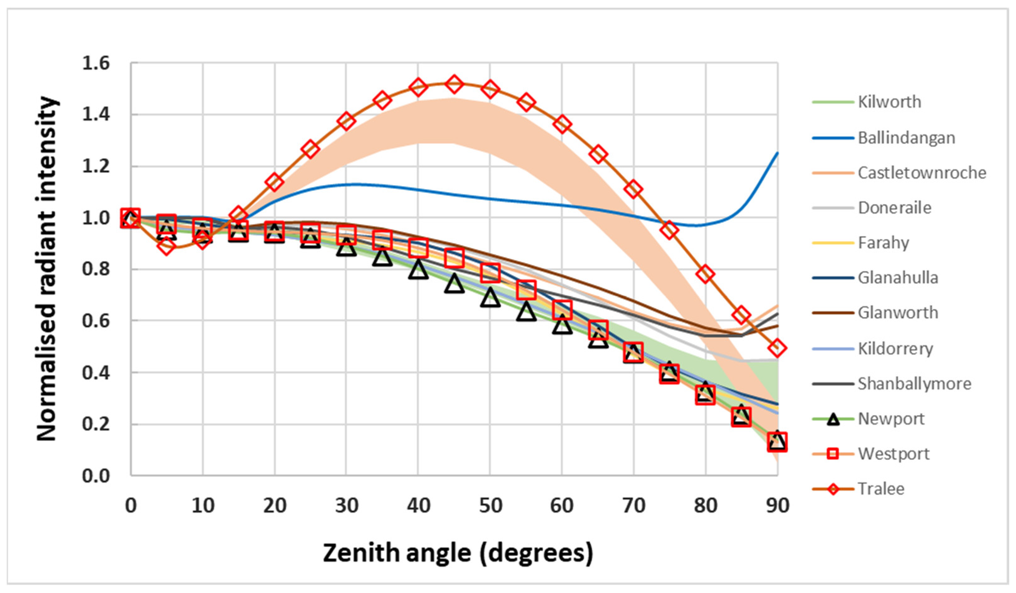
Figure 2, where the towns from Paper One are shown as lines, while the new towns introduced in this paper are shown with a combination of lines and open symbols. It is readily apparent that the results for Tralee follow the same trend as the residential cases containing this type of lantern, but since all the lighting is set to this one type, the model output is at the upper bound of the previous results and can be taken as the worst case scenario in terms of light pollution. We note that the diffuse component for this town follows almost exactly a pure Lambertian distribution, although, as noted in
Table 2, the fraction of the total upward emission escaping from individual areas varies from town to town and is always less than the obstruction-free case.
Figure 2 also shows that the town of Ballindangan, which we reported in Paper One to have the worst-case light emission, also has the largest near-horizontal emission and remains the worst example of this in the combined towns sample, although it has lower emission to intermediate angles. This low angle excess is due to the presence of LPS 55 W prismatic lensed lighting combined with a very open environment consisting of relatively wide streets and detached single-storey dwellings, which permit the escape of near-horizontal light to the wider environment.
3.3. Dublin City
To compare our results with those for more urbanised areas, we analysed the central Dublin test area presented in Paper One. This area lies approximately one kilometre from the city centre and consists mainly of mid-rise commercial buildings set along wide streets with narrower streets off them. Within the area are a number of enclosed public parks, and there are also a few boulevard areas. The 1 m resolution LiDAR data presented in Paper One were obtained in March 2015 when the trees were in leaf, while the 2 m resolution data presented here were obtained between December 2011 and February 2012. The model output for these two datasets is indicated in
Figure 3 by the curves marked “NYU area,” as the original dataset was taken as part of a New York University programme. There is very good agreement between the models based on the two seasonal datasets, with less than a 1% difference between the results in terms of both the total emission and its dominant diffuse component, and only a 3% increase in the weaker direct emission component between the summer and winter datasets. These results are, perhaps, to be expected as there is generally little tree cover aside from along the margins of the public parks where some lights are located, and also only relatively few cases where there are trees bordering the roadways.
In keeping with our previous observation that the biggest difference between models is due to the photometry of the predominant lantern type, we find that our result for the inner city area is roughly similar to that expected from one of the smaller residential areas with better-controlled lighting, consistent with the small proportion of 55 W LPS lanterns present in the inner city, which is dominated by higher wattage HPS lighting (see
Table 2 for numbers). In the same Figure, we also plot the curve derived by Falchi et al. [
8] from their inversion of global skyglow measurements, and it is heartening to see the close agreement between the two sets of results derived by different means, particularly in the case of the residential areas. We interpret this finding as follows: although other locations may have high-rise structures, it would be expected that the bulk of the emission at near-horizontal angles that contributes to skyglow in surrounding regions escapes from the low- and mid-rise areas with relatively few obstructions at low elevation angles. We also expect that the bulk of public lighting in the areas studied by Falchi et al. would now be of HPS type with better lighting control.
Also included in
Figure 3 is a test of our modelling approach to the entire Dublin City Council (DCC) area, amounting to over one hundred square kilometres and over 40,000 lanterns of both LPS and HPS types. The intention of this model was twofold: to see if the code would work efficiently with such a large area and the number of lanterns, and also to obtain an estimate of what the entire City Emission Function looks like for the case of well-controlled lanterns with no (or very little) direct emission above the horizontal. We thus restricted the model to a diffuse component only, and the model, including the generation of the base map of light pools around each light location and also the grid of shading models, ran in less than two hours on a modern 3.6 GHz CPU. It is notable that this model is almost identical to a Lambertian distribution, although, as seen in
Table 2, the emission to space is reduced relative to a model with no obstructions.
We calculated a version of the Li et al. [
12] “blocking index” for the whole of the DCC area for the case of the two azimuthal angles from which the city of Dublin is viewed by the SUOMI satellite, viz. 99° and 289°. Our approach differs from that of the Li et al. paper in that we used the GIS plugin for shadow depth to generate a raster masked to show the visible areas from a given azimuth and elevation—see
Appendix B for details. Having obtained masks for the required range of azimuths and elevations, a final output raster was generated for each azimuth in which each pixel contains the smallest elevation angle when that location first becomes visible, i.e., the blocking index value. Our approach has the advantage that it includes all obstructions over the entire mapped area simultaneously and is computationally efficient.
As the lit areas are also available, we can use these to weight the blocking index raster to select areas of relevance to the lit model. This has two advantages: firstly, that the numbers derived are for the individual locations, rather than random points along the street, and secondly, that better-lit locations receive a higher weighting, so the angle derived is more representative of the installed lighting. From our analysis, the minimum elevation angle required for a pixel to become visible is similar for both SUOMI azimuths and is equivalent to a zenith angle of 64° when averaged over the entire Dublin City Council (DCC) area. However, for an inner 2 km radius around the commercial heart of the city, the zenith angle is smaller by 6° (i.e., the elevation angle is larger) due to the presence of higher structures in this region. This finding indicates why the poorer lighting control of the 55 W LPS units is reduced towards higher zenith angles, as shown in
Figure 3. This reduction is important as light emission in the range 80° < zenith angle < 90° is the dominant contributor to rural skyglow. In comparison, the relatively unobstructed emission at lower zenith angles contributes predominantly to the urban skyglow [
13].
Although we do not incorporate an atmospheric scattering model in our calculations, we can give some approximate indications of potential light pollution through numerical integration of the light in the above angular ranges. One result is that we find that the ratio of light that can contribute in the “rural” to “urban” range is marginally lower in the LPS 55 W-dominated residential areas due to the increased proportion of light to lower zenith angles. When seasonal information is considered, this ratio increases from 4% in the winter data to 8% in the summer months, though it is also influenced by the restriction in light towards the zenith by tree canopies. For comparison, the ratio for towns (summer data only) ranges from 4% to 6%. Overall, we suggest that a “rural”/“urban” light pollution ratio of 6–7% during the summer months when foliage is present is a representative value for all locations examined.
3.4. Comparison with SUOMI Satellite Measurements
It has been pointed out by other authors ([
12,
14,
15]) that the SUOMI satellite observations of cities taken at different nadir angles show discrepancies in the observed radiance, indicative of variations in light output with angles that differ from a simple Lambertian assumption. There are two general effects which can be observed: a light distribution in which the observed radiance initially decreases with increasing zenith angle, and a distribution where there is an increase with zenith angle. The former behaviour is ascribed to the effect of high-rise buildings obstructing emission towards the horizon, and the latter occurs where low-rise buildings are present. While there are relatively few high-rise buildings in Irish cities, we can compare our predicted low-rise area light to that observed for other such locations using the atmospherically corrected fits reported in Table 3 of [
15].
For comparison with the Li et al. fits, in
Figure 4 we plot our model results in terms of radiance, i.e., with a correction for areal projection effects, consistent with the way data from the SUOMI or NOAA-20 VIIRS DNB instruments are processed and reported. Similarly, we restrict the plotted range to a maximum zenith angle of 70° for consistency with the range of reported satellite data. Plotted like this, a true Lambertian response will follow a horizontal line of unity as demonstrated, for example, by the case for the citywide diffuse-only model for Dublin (marked DCC in
Figure 4). A reasonable upper limit is provided by the topmost line, which represents the results for the town of Tralee, modelled assuming the worst-case 55 W LPS lanterns. The plot shows that the majority of our results lie within the boundaries of the observed global low-rise areas, which suggests that our models have a generic application.
3.5. Seasonal Effects
Although the impact of the high reflectivity of snow on light pollution has been discussed for other locations, snow events are relatively unimportant in the mild Irish maritime climate. However, the effect of snow on the ground is to increase the ground reflectivity, while leaving the direct emission unaffected, so we expect that for lanterns with relatively poor lighting control, the total detected output under such conditions will more closely approximate Lambertian emission when snow conditions are present.
Other than snow, a relatively large seasonal effect in temperate latitudes results from the change in vegetation levels over the year [
16]. Such effects can also be examined in our models as datasets covering a range of dates are available. For the case of Dublin, the higher resolution dataset was obtained in the months of May 2013 and June 2018, while the lower resolution dataset was obtained in the period from mid-December 2011 to early February 2012. We return to the residential areas previously discussed as these consist of relatively open areas of two-storey housing with differing amounts of trees lining the roads and so might show seasonal variations. In Paper One, we noted that aggregating digital elevation data from 1 m to 2 m pixels does not affect the overall normalised emission results, and we appeal to this finding when comparing these two datasets to determine the effects of foliage cover on the emission function.
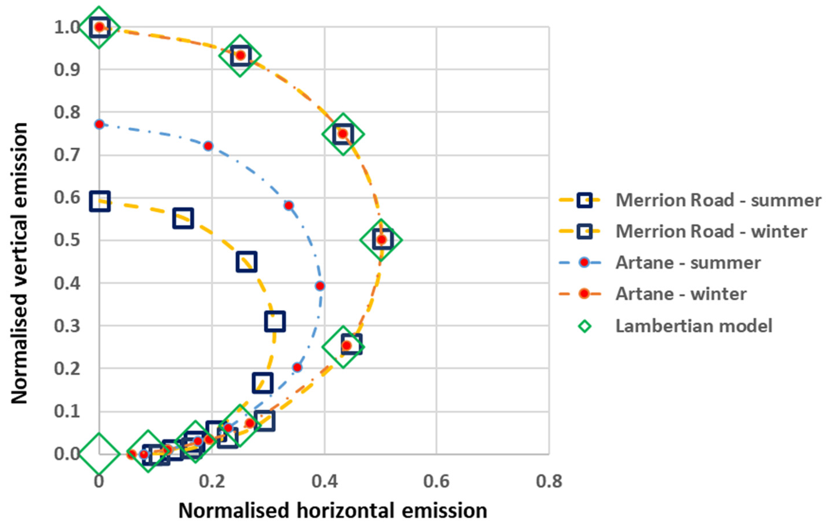
In
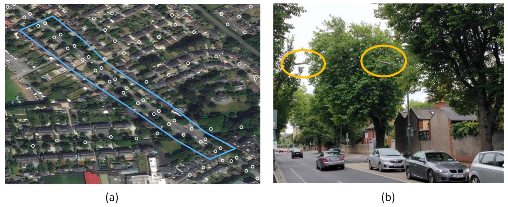
Figure 5, we plot two extreme cases of behaviour due to seasonal effects, normalised to the winter zenithal emission in each case. The upper (winter) curves for both locations agree with a Lambertian model to a high degree, but there is a noticeable reduction of light output during the summer months, which differs between the sites. The region with the largest effect is a straight road with fully mature tree canopies up to 13 m high, while the lanterns are 10 m above the roadway—see
Figure 6 for an illustration of the proximity of the tree canopies.
A comparison of the seasonal results shows a maximum decrease in total output by 38% between winter and summer for the Merrion Road case, which compares favourably with the 31% value reported for tree-lined streets in Cambridge, Massachusetts [
17]. Their result was obtained from sky visibility analysis derived from Google Street View imagery, though we note that our approach is much less computationally intensive. Representative results for other locations are listed in
Table 2.
3.6. Azimuthal Photometry
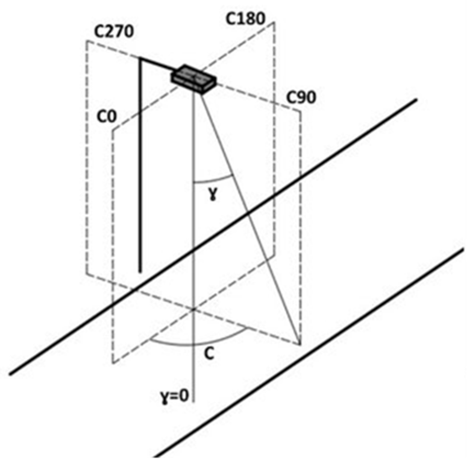
Our work to this point has made use of azimuthally averaged direct emission values based on similarly averaged luminaire photometry. This averaged direct emission is combined with the diffuse component to provide the total emission to space and the surrounding environment. The justification for this is that for relatively large numbers of well-distributed light sources, sampling of viewpoints to each light location should be (relatively) random, so azimuthally averaged values should be sufficient to provide relatively robust results. However, when we want to study small numbers of lights and/or a reduced set of orientations (e.g., when modelling a single straight road), then we need to consider that the lantern photometry is non-uniform in both azimuth and elevation and may, indeed, vary by location if lantern types differ. This is particularly true at low elevation angles (large zenith angles) as different light distributions are available for otherwise similar lanterns depending on the illumination required, e.g., on whether one or more carriageways of a road is to be illuminated. For most streetlights, the lighting distribution is chosen to produce an elliptical light distribution with its dominant direction along the street axis, i.e., in lighting photometric terms along the direction 0° < C < 180° (see
Appendix A for an illustration).
We updated our model to include a photometric angular dependence by incorporating OpenStreetMap data to determine the azimuth of the road segment closest to each light. A suitable change of reference then provides the C-angle appropriate to a viewpoint from due North, which is easily modified to deal with any given line-of-sight azimuth (see
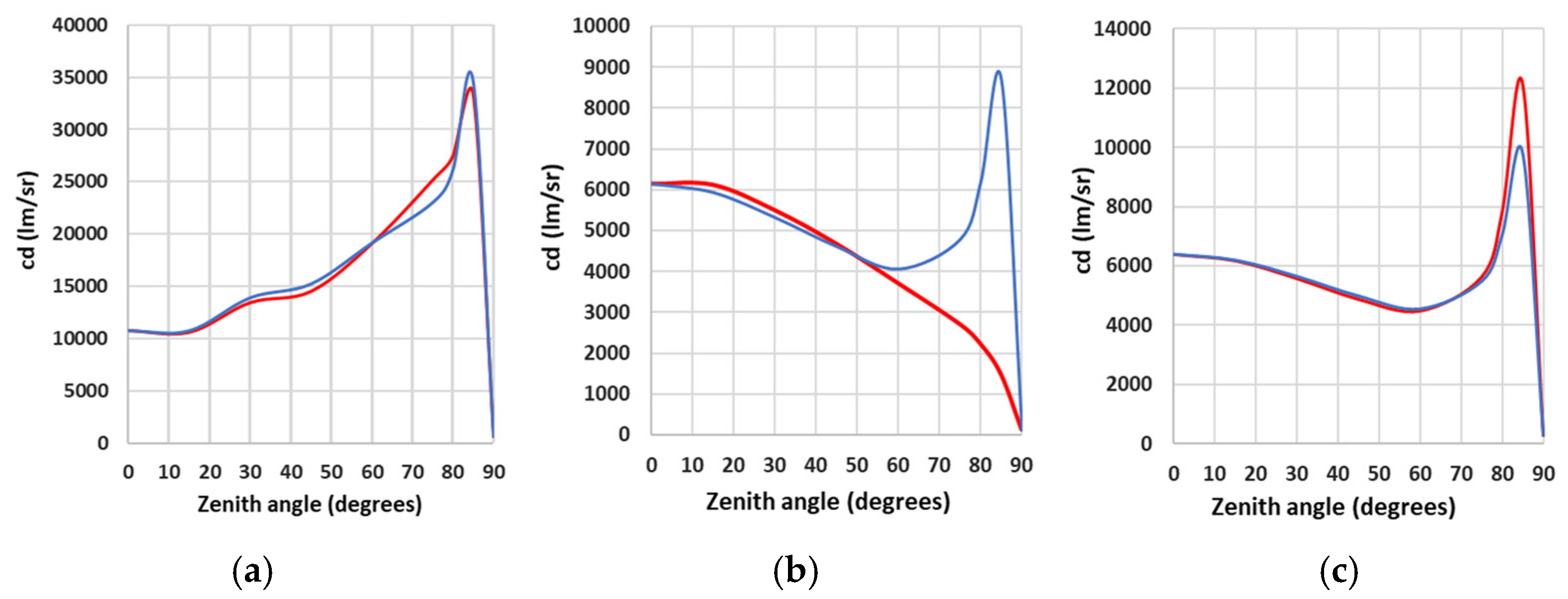
Appendix B). Finally, by referencing the specific photometric tables appropriate to each lantern, we can determine the appropriate value of direct emission in our calculations. In
Figure 7, we present a set of plots of the calculated total emission (diffuse + direct) for both azimuthally averaged and azimuth-specific values of direct emission to illustrate a range of conditions. By comparing the plots, it can be readily seen that at zenith angles below roughly 60°, there is relatively little difference between the two approaches, but for larger values, there is a variation in behaviour which is dependent on the lighting distribution and the relative orientation of the line-of-sight. As expected, the housing estate case with a more random distribution of orientations (
Figure 6a) is closest to the averaged values, but relatively large deviations (and in opposite senses) are found for the other two cases, which model single lines of streetlights.
The results suggest that large-scale modelling can be approached using averaged photometry, particularly for near-nadir satellite observations, but there can be differences in detail when individual areas are intercompared. This is especially true when modelling or comparing observations of areas of differing geometry and/or complexity, particularly in the case of light emission at near-horizontal angles appropriate to health and environmental impact studies.
3.7. Quantitative Comparison to ISS Data
As noted earlier, we located an image of Dublin (ISS045-E-170140) taken from the International Space Station in winter 2015, which had both good resolution (≈16 m/pixel) and was roughly contemporaneous with both the digital elevation and public lighting data. This image was georeferenced, calibrated to radiance units and corrected for atmospheric absorption and scattering by Dr. Alejanandro Sanchez de Miguel. We used the radiance-calibrated images in the G (green) band as these are roughly coincident with the photopic band used for determining our model radiances and hence facilitated comparison with our model output. In addition, by incorporating the known image corner coordinates into the NASA image footprint calculator spreadsheet, we could determine the location of the viewpoint relative to the ground and hence the appropriate azimuth and nadir angle to model (
https://eol.jsc.nasa.gov/SearchPhotos/Low_Oblique_301_Locked.xls (accessed on 3 June 2023)).
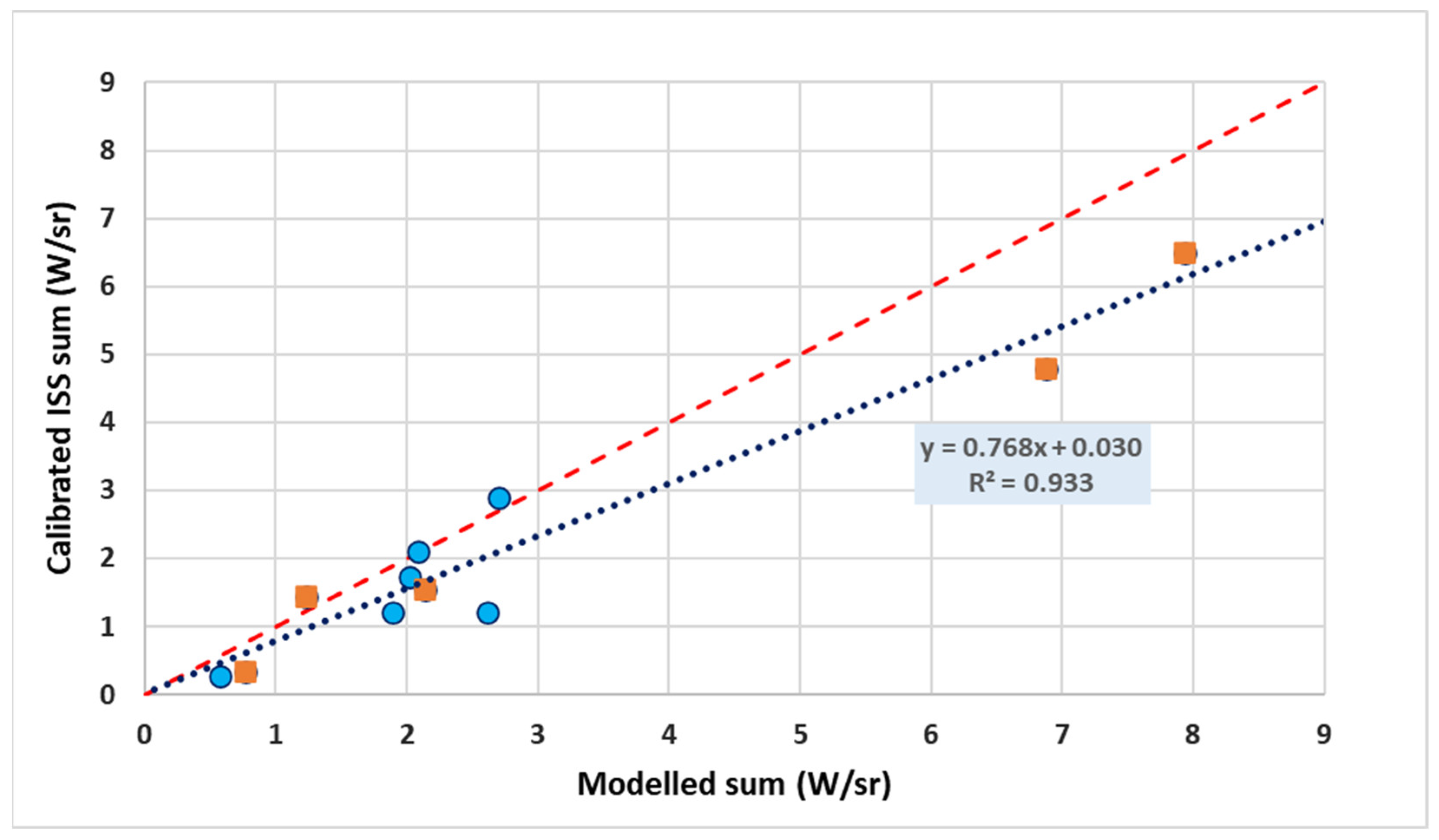
As test areas, we used the Dublin residential locations discussed above, which we knew to be dominated by LPS emission. By using vector shapefiles, we were able to extract both model and observed radiances for each of the residential areas and compare them after converting both sets of measurements to watts per steradian. As before, we used a uniform reflectance of 10% for all areas and did not adjust the model output to account for any differences in environment or orientation beyond the selection of the appropriate azimuthal photometry for the observation geometry. The data can be seen in
Figure 8, together with the best-fit linear model to the data. From the correlation coefficient of 0.93, it can be seen that there is a very good agreement between the model output and the observations. While our model results are, in general, slightly offset to higher values than observed, we note that we have not attempted to account for degradation in light output due to the total failure of individual lamps nor for the progressive decrease in output due to lamp degradation and/or dirty lantern lenses; in technical terms, the maintenance factor has been set to unity for all locations.
This approach to testing our model makes use of the near-monochromatic output of LPS lamps present at the time of observation and modelling. Our approach would be more complicated to apply with broad-spectrum lighting sources or for detectors with different spectral responses or, indeed, panchromatic imagers such as VIIRS DNB, even without consideration of the more complex atmospheric transfer for broadband spectra. However, we believe that this result is the first such detailed comparison between model and observation and that it vindicates our overall approach.
