Article

Research on Arc Sag Measurement Methods for Transmission Lines Based on Deep Learning and Photogrammetry Technology

1
Chinese Academy of Surveying & Mapping, Beijing 100036, China
2
School of Geomatics, Liaoning Technical University, Fuxin 123008, China
3
China Huaneng Zhalainuoer Coal Industry Co., Ltd., Hulunbuir 021000, China
4
College of Ecology and Environment, Xinjiang University, Urumqi 830046, China
*
Author to whom correspondence should be addressed.
Remote Sens. 2023, 15(10), 2533; https://doi.org/10.3390/rs15102533
Submission received: 23 February 2023 / Revised: 6 May 2023 / Accepted: 9 May 2023 / Published: 11 May 2023

Abstract

:
Arc sag is an important parameter in the design and operation and maintenance of transmission lines and is directly related to the safety and reliability of grid operation. The current arc sag measurement method is inefficient and costly, which makes it difficult to meet the engineering demand for fast inspection of transmission lines. In view of this, this paper proposes an automatic spacer bar segmentation algorithm, CM-Mask-RCNN, that combines the CAB attention mechanism and MHSA self-attention mechanism, which automatically extracts the spacer bars and calculates the center coordinates, and combines classical algorithms such as beam method leveling, spatial front rendezvous, and spatial curve fitting, based on UAV inspection video data, to realize arc sag measurement with a low cost and high efficiency. It is experimentally verified that the CM-Mask-RCNN algorithm proposed in this paper achieves an AP index of 73.40% on the self-built dataset, which is better than the Yolact++, U-net, and Mask-RCNN algorithms. In addition, it is also verified that the adopted approach of fusing CAB and MHSA attention mechanisms can effectively improve the segmentation performance of the model, and this combination improves the model performance more significantly compared with other attention mechanisms, with an AP improvement of 2.24%. The algorithm in this paper was used to perform arc sag measurement experiments on 10 different transmission lines, and the measurement errors are all within ±2.5%, with an average error of −0.11, which verifies the effectiveness of the arc sag measurement method proposed in this paper for transmission lines.

Graphical Abstract

1. Introduction

Arc sag is one of the important parameters in the design, operation, and maintenance of transmission lines, reflecting the tightness of overhead lines. Arc sag that is too large or too small brings safety risks to the operation of transmission lines; arc sag that is too small can easily lead to greater stress inside the wire, which leads to wire fracture and tower collapse, as well as other accidents; arc sag that is too large can easily lead to wire-and-ground physical contact, and discharge accidents. As the line ages, the operating load and the surrounding environment cause changes in the arc sag, so there is a need for regular testing of arc sag. An early commonly used method is the manual observation method, which is able to measure the transmission line arc sag with high accuracy, but this method is greatly limited by the often-complex terrain and harsh environment along high-voltage transmission lines. Many studies have therefore proposed methods that can calculate arc sag and identify key features on transmission lines. For example, the theoretical values of arc sag are calculated by obtaining mechanical parameters such as conductor tension, material properties, wind speed, and power line temperature. Ramachandran and Vittal et al. [1] proposed a computer program to calculate arc sag on transmission lines based on conductor tension and temperature, and Lijia et al. [2] used monitoring of real-time tension to calculate arc sag values for stall distances. However, the line equation to calculate arc sag based on these parameters is very complex, and only a few studies have established the corresponding line equation for each stall distance. For example, Dong et al. [3] used a single equation to determine the conductor tension within a stall distance to calculate the arc sag using the relationship between the temperature, tension, and strain of the conductor, achieving an error of less than 1%.
To directly measure the arc sag, several real-time arc sag monitoring devices have been developed and produced by domestic and foreign power departments. For example, the CAT-1 produced by The Valley Group Inc. in the United States calculates the arc sag by measuring the wire stress [4], and the Power-Donut2 produced by USI in the United States and the MT series produced by Haikang Thunderbird in Hangzhou calculate the arc sag in real time by measuring the temperature of the wire or the dip angle of the suspension point [4]. In addition, Mensah-Bonsu et al. [5] used a relatively advanced technique called differential GPS (DGPS) to measure arc sag, where the positioning signal obtained from an arc sag detection device installed on a transmission line is corrected for differential errors by a DGPS base station to obtain more accurate information about the location of the transmission line. Wydra et al. [6] introduced a chirped fiber Bragg grating (CFBG)-based optical sensor to determine the correlation between spectral width and arc sag variation to measure arc sag. There have also been studies using cable climbing robots to measure transmission line arc sag [7], but the practical application of this method has not been proven. Invariably, these arc sag monitoring devices require the installation of various sensing devices on transmission lines, such as magnetic field sensors and transmission line reconnaissance robots, which, in addition to being expensive to detect and maintain, are difficult to operate properly in environments with strong electromagnetic fields, making long-term operation a challenging task.
Synchronized voltage and current phase quantities have also been used for arc sag monitoring with the help of synchronous phase measurement units (PMUs) [8]. Oleinikova et al. [9] presented a method to calculate real-time arc sag values and transmission line temperatures using different transmission line parameters obtained from synchronized PMUs. In addition, it was shown that magnetic fields generated by power lines can also be used to calculate arc sag. Khawaja et al. [10] correlated arc sag with propagating signals between power line carrier (PLC) stations to measure arc sag, and Sun et al. [11] proposed a magnetic-field-based technique for noncontact operational condition monitoring of high-voltage transmission lines, for the ground elevation of transmission lines operating in different states, while measuring electrical and spatial real-time parameters to calculate the arc sag.
With the development of UAV technology, the use of airborne visible, infrared, and LiDAR equipment to collect a large amount of transmission line data and obtain the operational status of transmission lines through the processing of these data has become the current mainstream technology [12,13,14]. Unmanned airborne LiDAR power inspection technology measures arc sag values by acquiring high-precision and high-density 3D spatial point cloud data of transmission lines and reconstructing the point cloud data. Ma et al. [15] used reconstructed 3D spatial models of transmission lines with arc sag simulation equations to realize 3D spatial morphology simulations of transmission line arc sags under different meteorological conditions. Du et al. [16] used laser point clouds of transmission lines and the BIM design model as the basis of data fusion and obtained the arc sag measurement results by inter-model comparison. These methods are based on the reconstruction of the transmission line 3D model method, combined with the spatial curve fitting technique to calculate the arc sag parameters. However, the expensive LiDAR equipment and a large amount of point cloud data lead to the high cost of this type of method, which is not suitable for rapid inspection of transmission lines on a large scale and periodically.
In contrast, the technique of transmission line arc sag measurement based on aerial images from UAVs is more popular. Sermet et al. [17] proposed a mobile application to monitor transmission line arc sag by enhancing image recognition. Lu et al. [18] used beam method parity optimization and built a cubic grid point model to obtain line parameters of transmission lines in solid space to achieve arc sag measurement. Tong et al. [19] measured the coordinates of the isolated bar center using the image processing method and calculated the arc sag of the transmission line based on the stereo vision technique and the least squares linear regression algorithm. These methods mostly use traditional algorithms such as image matching to identify the spacing bars when extracting the feature points on the transmission conductors, which leads to unstable matching accuracy that is easily affected by the noise in the image background and requires manual intervention, which is less efficient. In addition, some scholars use digital image processing techniques to locate and extract transmission lines, reconstruct the lines’ 3D vector to calculate the arc sag index through the hanging chain line fitting technique [20], or use computer vision technology and photoelectric technology to perform noncontact measurement of the transmission line arc sag [21]. However, these methods have the same drawbacks: low efficiency, high cost, more manual intervention required, and the inability to overcome the interference of complex image backgrounds.
For the above problems with these methods, this paper proposes a transmission line arc sag measurement method based on UAV aerial photography. This method is based on UAV aerial video and uses the transmission line spacer bar automatic segmentation algorithm CM-Mask-RCNN, which incorporates the coordinate attention block (CAB) [22,23,24] and multi-head self-attention (MHSA) [25,26,27] attention mechanisms; using these, the automatic segmentation of spacer bars and extraction of center coordinates, combined with the algorithms of beam method leveling, spatial front rendezvous, and spatial curve fitting can quickly achieve transmission line arc sag measurement. This method has the advantages of high efficiency, speed, reliability, low cost, and independence from geographical influence, which can allow it to realize the measurement of arc sag parameters in the daily inspection process and has high engineering application value.

2. Related Work

2.1. Survey Area Overview

The study area for the arc sag measurement experiment of this transmission line was selected in the line from tower 09 to tower 37 of the Yangu line in Daling village, Dapu town, Hengdong county, Hunan province, China (as shown in Figure 1). The study area is mainly plain; the average elevation of the ground is about 80 m; the maximum height difference is about 22 m, adjacent to the village; and there are no tall buildings around. The study area covers a variety of land types such as houses, roads, forests, farmlands, grasslands, ponds, and water surfaces, which comprehensively reflects the complex geographic environment around the transmission line.

2.2. Data Acquisition

After setting up control points in the study area, a Phantom 4 RTK UAV was used to collect video data of the transmission lines. The UAV has a centimeter-level navigation and positioning system for precise positioning, navigation, and route planning, and is capable of sensing the three-dimensional spatial environment. It is capable of capturing 4K slow-motion video at a high bit rate of 100 Mbps at 60 frames per second. Therefore, it is often used for low-altitude photogrammetry in forestry, agriculture, and power inspection. Its parameters are shown in Table 1.
The UAV camera needs to be calibrated for aberrations and internal orientation elements before data acquisition. There are two main types of camera aberrations: cushion aberrations and barrel aberrations.
The camera calibration formula is as follows:
Δ x = ( x x 0 ) ( k 1 r 2 + k 2 r 4 ) + p 1 [ r 2 + 2 ( x x 0 ) 2 ] + 2 p 2 ( x x 0 ) ( y y 0 ) + α ( x x 0 ) + β ( y y 0 ) Δ y = ( y y 0 ) ( k 1 r 2 + k 2 r 4 ) + p 2 [ r 2 + 2 ( y y 0 ) 2 ] + 2 p 1 ( x x 0 ) ( y y 0 )
The camera can be calibrated to obtain the internal orientation elements and distortion parameters of the lens, as shown in Table 2.
When using unmanned aerial vehicles to collect data, we used manual control mode to approach the transmission line as close as possible under the premise of meeting the safety distance from the electric tower. Considering the regional environment and security constraints, the drone flew directly above the power transmission line at a height of 45 m from the ground and 10 m from the highest point of the electric tower. In addition, the camera carried by the drone was set to the following parameters: the shutter time was 1/1000 s; automatic aperture was used; the sensitivity was ISO200; and the fixed focus f was 8.8 mm. At this time, the ground resolution was about 1.5 cm, and the spacer resolution was about 1 cm.

3. CM-Mask-RCNN-Based Transmission Line Spacer Bar Automatic Segmentation Network

3.1. CM-Mask-RCNN Framework

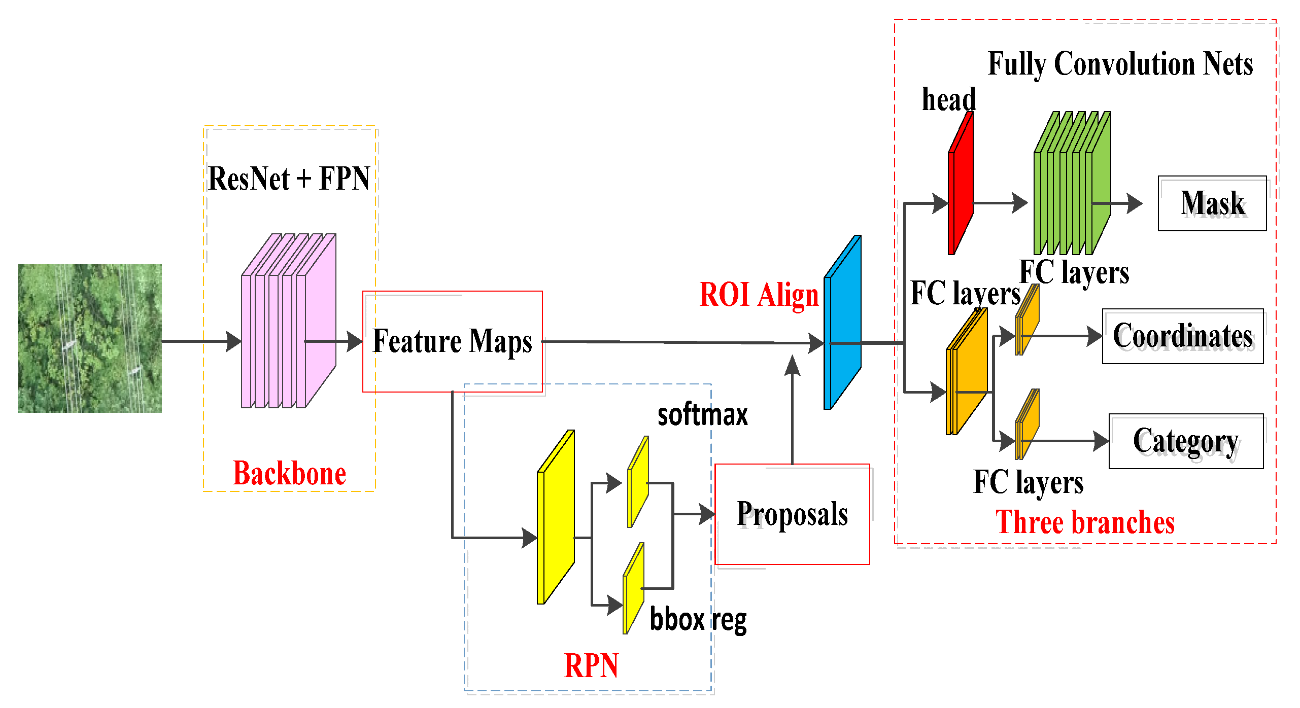
When extracting the spacer bars in transmission lines, to make the model allocate more attention to the spacer bar region, suppress useless information, and then improve the feature learning and feature representation capability of the network, we reconstructed the feature extraction network based on the Mask-RCNN [28,29,30] network, designed and added a coordinate attention block after each residual block of ResNet50, introduced a multi-head self-attention block to replace the 3 × 3 spatial convolution in C5 of ResNet50, and proposed the transmission line spacer bar automatic segmentation network CM-Mask-RCNN.
As shown in Figure 2, CM-Mask-RCNN has the same overall framework as Mask-RCNN, which mainly consists of three parts: a feature extraction network, region candidate networks (RPNs), and a head network. After the feature extraction network extracts the feature map of the input image, the candidate region is obtained by RPNs, and the candidate region feature map is obtained through the ROI Align layer and input to the head network, where the probability of the presence of lesions in the candidate region is evaluated, and the location and size of the candidate region are corrected to segment the spacer bar lesion region within the candidate region. The candidate regions with a small probability of the presence of lesions and the candidate regions with high overlap are removed using the non-maximum suppression method to obtain the final candidate region and lesion segmentation results.
Unlike the Mask-RCNN network, CM-Mask-RCNN introduces CAB and MHSA in ResNet50 to improve the feature extraction network. ResNet50 in Mask-RCNN is divided into Stage 1–Stage 5, where Stage 1 consists of a convolutional layer and a maximum pooling layer. Stage 2–Stage 5 consist of a stack of residual blocks. By reconstructing the residual blocks and designing and adding CAB after the three convolutional layers in the residual blocks, the position information of the spacer bars is also embedded in the channel attention when feature learning is performed, so that the model can not only capture long-range correlations along one spatial direction, but also retain the precise position information along another spatial direction, and devote more attention and resources to the target region of the spacer bars while still retaining the precise location of the spacer bar, improving the efficiency and accuracy of the model’s visual information processing. In addition, to improve the performance of the model for the small target segmentation task, we introduced a multi-head self-attention block to replace the 3 × 3 spatial convolution in Stage 5 of ResNet50, using the global self-attentive mechanism to process the information contained in the feature maps captured with the aggregated convolution.

3.2. Mask-RCNN Network

Mask-RCNN [30] is a classical instance segmentation algorithm whose main idea is to resegment based on the target detection algorithm Faster-RCNN [31], and its performance in target recognition and image segmentation makes it one of the best algorithms at present [32,33,34,35]. Mask-RCNN is further extended based on Faster-RCNN, and can overall be divided into three parts: a feature extraction network, a region candidate network, and a function network. In the feature extraction network, ResNet [36,37,38] is used as the backbone network to extract feature elements at multiple scales by building bottom-up feature pyramid networks (FPNs) [39,40,41]. The regional candidate network generates feature maps based on Faster-RCNN with ROI Align instead of ROI Pooling, which can effectively improve the accuracy of the model. Finally, full connection classification, border regression, and mask regression are used in the functional network branch to realize the instance segmentation task, and its network structure is shown in Figure 3.

3.3. Coordinate Attention Block

The spacer bars only occupy a small part of the image area, and most of the content is the natural background. To eliminate redundant feature information irrelevant to the spacer bars and improve the feature extraction capability of the spacer bar detection model, the residual blocks are reconstructed in ResNet50, the backbone network of Mask-RCNN, and the CAB attention module is designed and added. The features of the extracted spacer bars are feature rescaled to automatically filter unimportant information and devote more attention to the target regions that need to be focused, improving the efficiency and accuracy of spacer bar extraction.
CAB is a lightweight convolutional attention module that, unlike classical attention mechanisms such as SE that only consider inter-channel information for coding, embeds location information into channel attention as well, allowing the model to capture long-range correlations along one spatial direction while retaining accurate location information along another spatial direction, and its network structure is shown in Figure 4. In using this module, the global average pooling (AvePooling) operation is first used to obtain the height feature M a v e H e i g h t and the width feature M a v e w i d t h of the feature map F G . Subsequently, the features in both directions are concatenated, and a 2D convolutional layer, BN layer, and h_swish activation function are accessed to construct the remote dependencies. The purpose of blending the information in X and Y directions is achieved. The blending process is shown in Equation (2):
M ave θ = AvgPooling ( F G ) M XY = δ   [ Conv 2 D M ave Height M ave Width ]
where θ { Height ,   Width } , ⊕ denotes feature connectivity and δ denotes the h_swith activation function. At this point, each dimension of the feature map M XY contains all the global information. Next, we access the feature map M XY to create a split function to separate it and scale the values between 0 and 1 using the Sigmoid activation function to obtain two sets of weight maps along the two directions of height and width. Finally, we perform the dot product operation on these two sets of weight maps to obtain weight maps with weights in X and Y directions.

3.4. Multi-Head Self-Attention Block

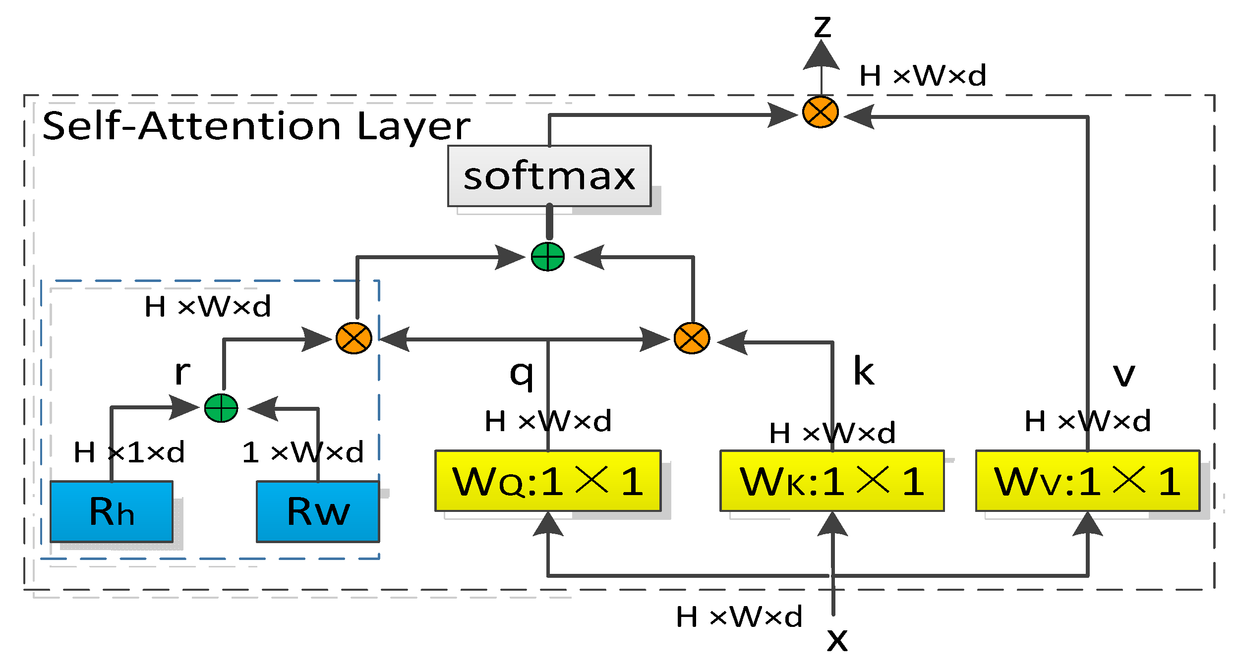
To improve the performance of the model in small target detection, we introduced multi-head self-attention (MHSA) in the backbone network. Compared with the traditional convolutional structure that captures local information in a global aggregate by stacking many convolutional layers, MHSA uses a global self-attention mechanism to process and aggregate the information contained in the feature maps captured by the convolution. It is very similar to multi-head self-attention in Transformer, but the difference is that MSHA treats position encoding as spatial attention, embedding two learnable vectors as spatial attention in both the horizontal and vertical dimensions, and then the summer and fused spatial vector is multiplied with q to obtain the protect-position, and the content-position and content-content are multiplied to obtain the spatial sensitive similarity feature (as shown in Figure 5).
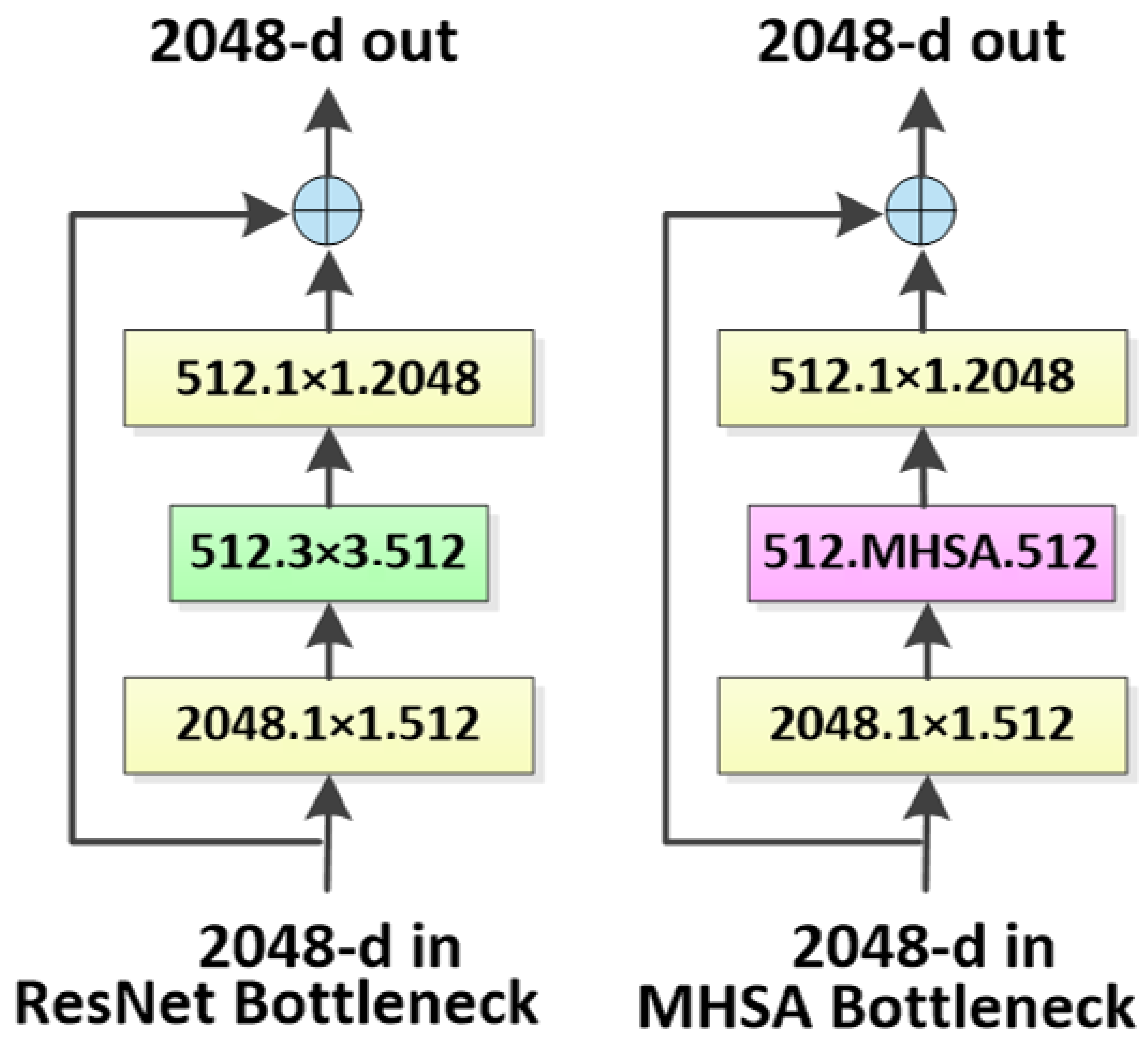
By replacing the 3 × 3 spatial convolution in the last three bottleneck blocks of ResNet using MHSA (as shown in Figure 6), global self-attention on the 2D feature maps enables the model to process and summarize the information contained in the feature maps while effectively learning the abstract and low-resolution feature maps in large-scale images using convolution, which can effectively improve the performance of the model’s feature extraction.

4. Transmission Line Arc Sag Measurement

Transmission line arc sag refers to the transmission line, the lowest point of the transmission line between two adjacent towers, and the vertical distance between the two hanging suspension point lines. Due to the self-weight of the conductor, the overall shape of the transmission line is within a distance similar to a parabola, so the arc sag measurement is commonly used to fit the data regression algorithm space curve equation (parabolic equation) to calculate the arc sag. When fitting the parabolic equation, multiple feature points need to be selected on the transmission line, but the transmission conductor has a single feature and it is difficult to select the feature points. In a stall distance, there are about 5–9 spacer bars, and using the spacer bar center as a feature point becomes a good choice. By extracting the coordinates of the center of the spacer bar, combining the imaging parameters obtained by the beam leveling method, establishing the image point relationship of the same spatial point in different images, and using the spatial front rendezvous algorithm to obtain the spatial coordinates of the feature points, the three-dimensional information of the scene is recovered.
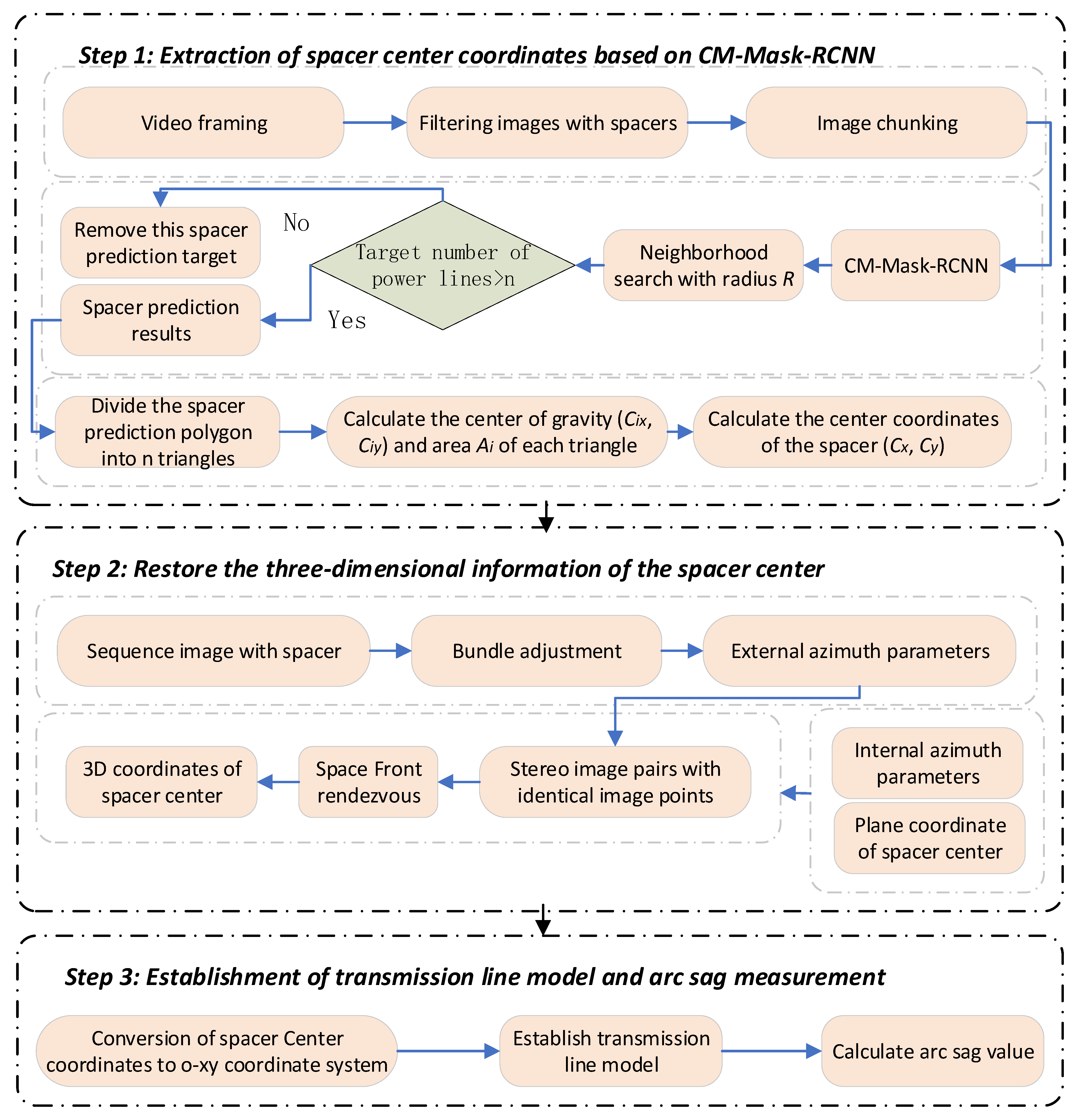
To solve the problems of the manual selection of feature points and time-consuming image matching during arc sag measurement, this paper proposes a new method for transmission line arc sag measurement, which is divided into three steps: in the first step, the coordinates of the center of the spacer bar are extracted based on CM-Mask-RCNN; in the second step, the 3D information of the center of the spacer bar is recovered; and in the third step, the transmission line model and arc sag measurement are established. The technical flow of the method is shown in Figure 7.

4.1. Extraction of Spacer Bar Center Coordinates Based on CM-Mask-RCNN

Sequence images are obtained using frame extraction of the UAV transmission line inspection video. Due to the faint spacing bars and power line targets, the pixel share is small, which brings greater difficulties to the feature extraction stage. Given this, this paper uses the chunking strategy with the idea of local first and then whole, chunking the images and then inputting them into CM-Mask-RCNN in sequence for prediction, and finally stitching the obtained local prediction result map to obtain the complete output map.
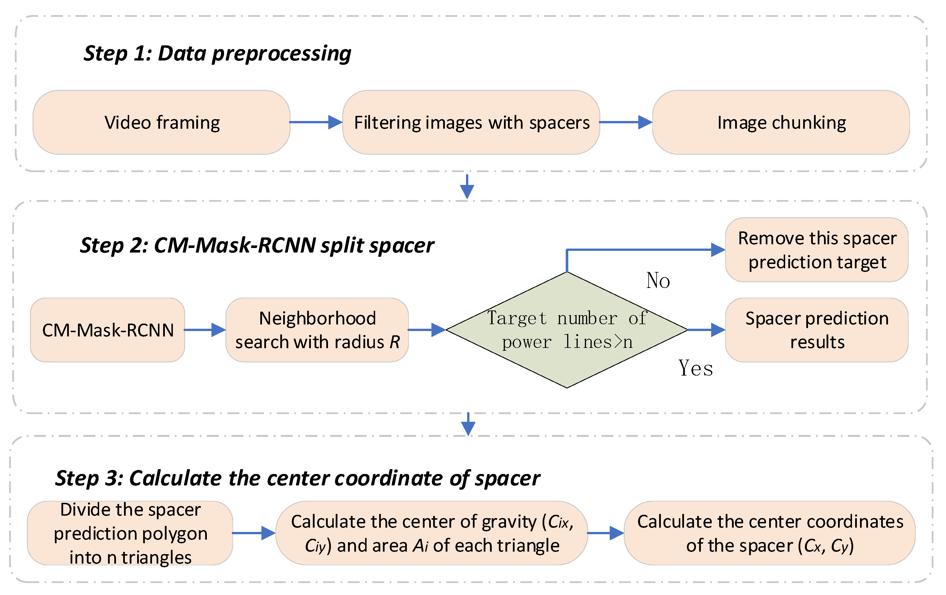
There are inevitably some targets with similar characteristics to the spacer bars in the transmission corridor under complex scenes, which leads to some false detections in the predicted results by the CM-Mask-RCNN model, which causes greater interference in the later task of spacer bar center coordinate extraction. In this paper, the joint features of spacer bars and transmission lines were combined to eliminate false detection targets. In constructing the joint features, considering that each spacer bar is connected with power lines, we searched the mask graph predicted by CM-Mask-RCNN with the center of the spacer bar as the center and R as the radius, and if there were n power line pixel points in the range, it was marked as a spacer bar; otherwise, it was a false detection target. A flowchart of extracting spacer bar center coordinates using CM-Mask-RCNN is shown in Figure 8.
In calculating the center coordinates of the spacer bar, the mask of the spacer bar is viewed as a polygon, so the task can be classified as calculating the center-of-gravity coordinates of the polygon. First, the polygon is dissected into n triangles X1, X2, ..., Xn, the center-of-gravity point ( C i x , C i y ) of each triangle is calculated with area A i ; then, the center-of-gravity coordinates of this polygon are ( C x , C y ) , and the calculation formula is as follows:
{ C x = C i x A i A i C y = C i y A i A i

4.2. Recovery of 3D Information in the Center of the Spacer Bar

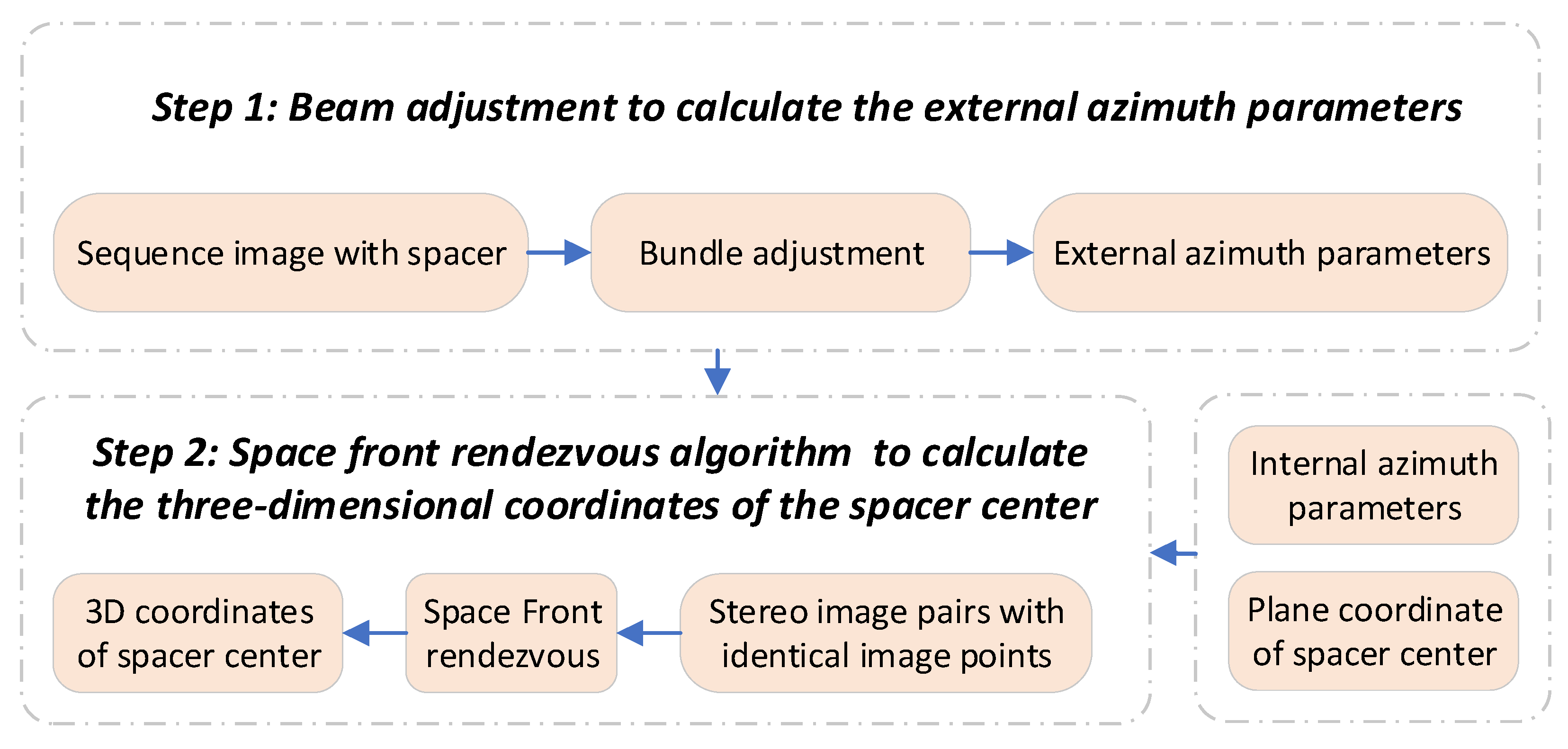
CM-Mask-RCNN extracts the spacer bar center coordinates as image plane coordinates, and the spacer bar center coordinates are used to fit the power line model to the 3D spatial coordinate system. The technique is divided into two steps: in the first step, the beam leveling algorithm solves the external orientation parameters; in the second step, the space front rendezvous algorithm solves the 3D coordinates of the spacer bar center. The flow of this technique is shown in Figure 9.

4.2.1. Calculation of External Azimuth Parameters with Bundle Adjustment

The accuracy of calculating the coordinates of the target point in solid space depends entirely on the accuracy of the parameters at the time of camera imaging. The DJI Genie Phantom 4 RTK UAV is a consumer-grade product, and its result error is hardly satisfactory. Therefore, the beam method area network leveling method is used, in which each beam (image) is used as the basic leveling unit, the colinear equation of the central projection is used as the base equation for leveling, and the leveling process is carried out uniformly in the whole area to solve the external orientation parameters of each photograph.

4.2.2. Space Front Rendezvous Algorithm for Computing Ground Coordinates of Spacer Center

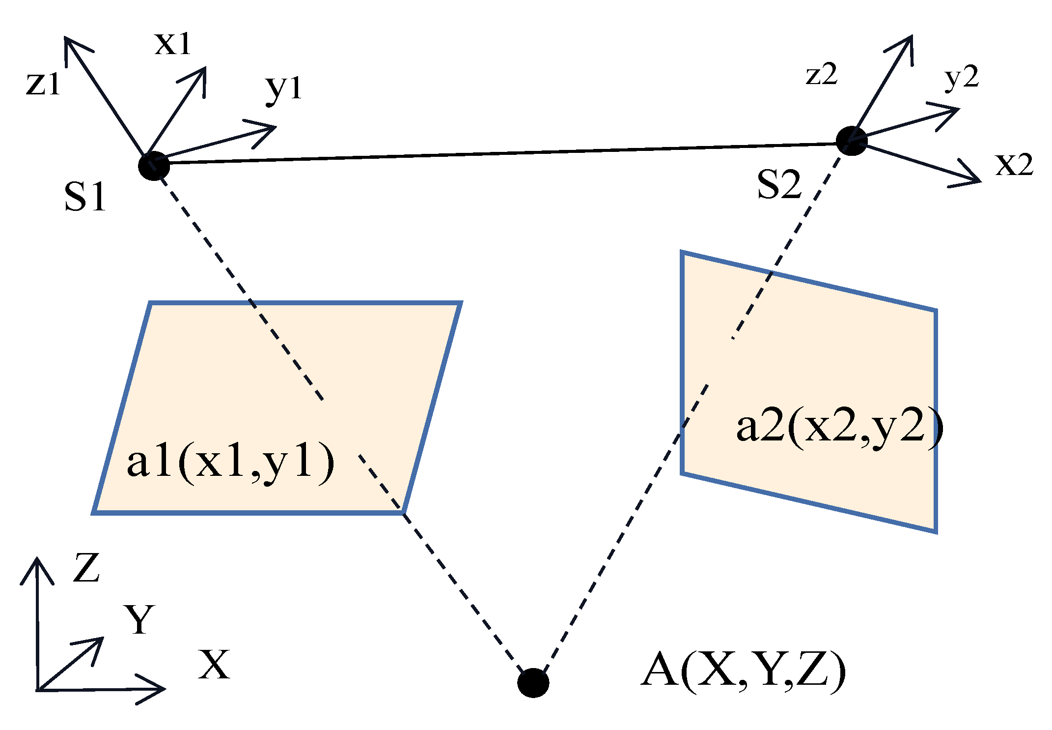
The point where the two rays intersect in space, i.e., the spatial position of the ground point, can be obtained using the eponymous image point of the stereo image pair. The algorithm for the spatial front rendezvous of a stereo image pair determines the ground coordinates of the corresponding ground point by using the internal and external orientation elements of the stereo image pair and the coordinates of the eponymous image point; the principle of the algorithm is shown in Figure 10.

4.3. Establishment of Transmission Line Model and Arc Sag Measurement

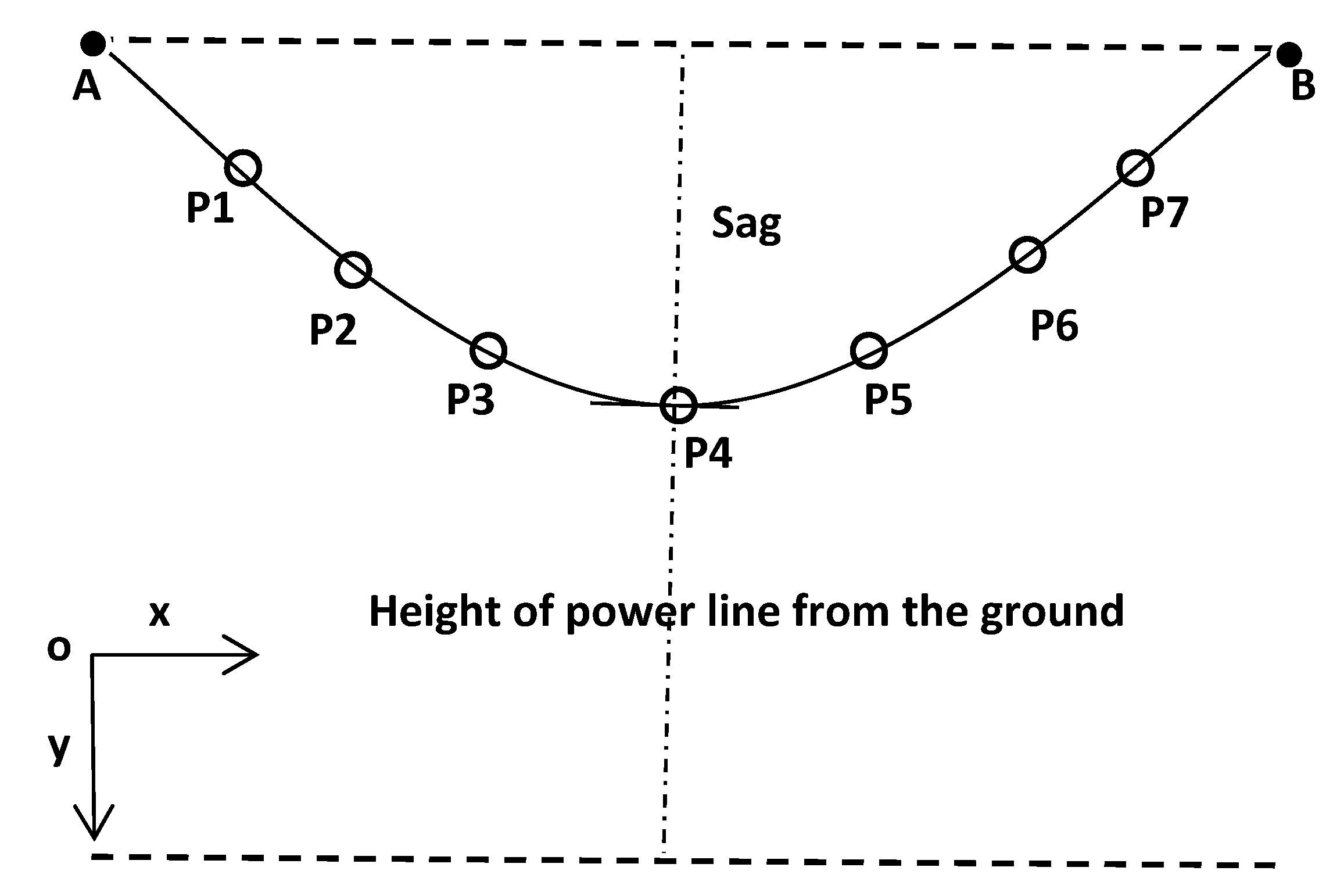
The parabolic equation of a transmission line within a stall distance can be calculated by data regression if multiple feature points are extracted from the transmission line due to the overall parabolic-like shape of the self-weight. The parabolic equation of the transmission line is fitted by using the center of the spacer bar as a feature point, plus two lifting points on the front and rear towers. To facilitate the calculation, the spatial coordinates of these points ( x i ,   y i ,   z i ) are converted to the o-xy coordinate system as shown in Figure 11. This coordinate system takes the electric tower crane point A as the origin of the coordinate system; the line connecting A and B is the x-axis and points to B, and the y-axis is perpendicular to the x-axis and points to the ground direction.
The transmission line parabolic equation is expressed as follows:
y = a 0 + a 1 x + a 2 x 2
where y is the vertical coordinate of a point on the transmission line; x is the spacing between two towers; and a0, a1, and a2 are the coefficients to be determined.
E = i = 1 7 δ i 2 = i = 1 7 | y i y ( x i ) | 2 = min
Combined with the above equation, the spacer bar center coordinate data are fitted; then, the pending coefficients a0, a1, and a2 can be calculated to obtain the spatial curve equation of the transmission line, when y is the maximum value, that is, the arc drape value of the transmission line.

5. Experimental Results and Analysis

5.1. Dataset and Evaluation Criteria

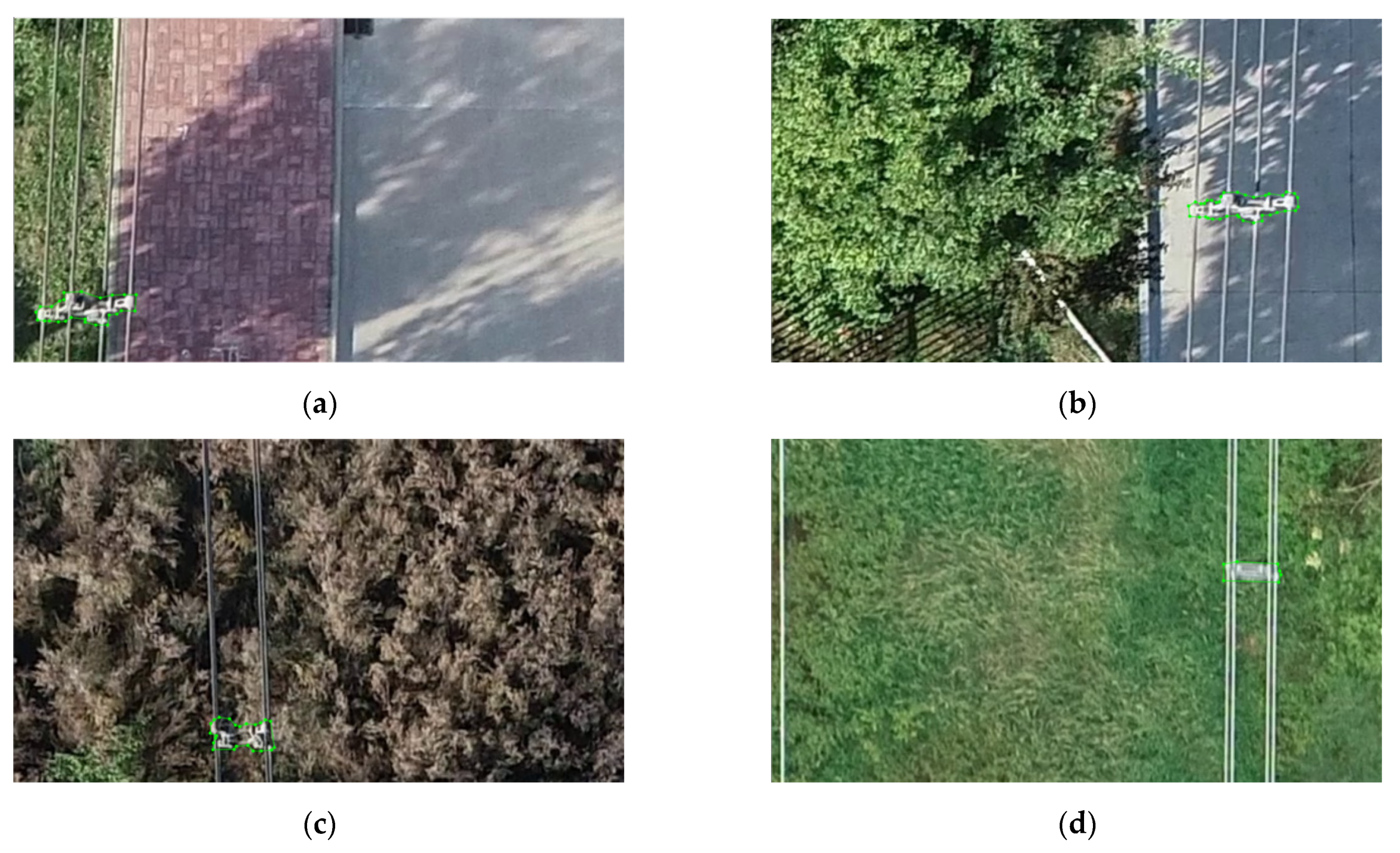
To verify the performance of the CM-Mask-RCNN transmission line spacer bar automatic segmentation model proposed in this paper, 850 UAV transmission line spacer bar images with image backgrounds covering forests, grasslands, cultivated land, roads, houses, and pond water were selected and labeled with labelme to divide the training set and test set according to the ratio of 7:3. An example of this dataset is shown in Figure 12.
In this dataset, the prediction results of the spacer bars were evaluated using average precision (AP), calculated as follows:
AP = i ( R i R i 1 ) P i
where P i is the checking accuracy of target category i, and R i is the checking rate of target category i.
In addition, the commonly used evaluation metrics are AP50, AP75, APS, and APM, where AP50 and AP75 are the average segmentation accuracies calculated when the IOU is 0.5 and 0.75, respectively, and APS and APM are the average segmentation accuracies of small and medium-sized targets, respectively.

5.2. CM-Mask-RCNN Model Training

Before the transmission line spacer bar automatic segmentation model training begins, the dataset needs to be converted to the COCO dataset format. The pretraining file is mask_rcnn_R_50_FPN_3x with the CM-ResNet50-FPN model as the backbone network and the hyperparameters of the model are obtained using a genetic algorithm. The initial hyperparameters are shown in Table 3.

5.3. Comparison and Analysis of Transmission Line Spacer Bar Extraction Experiments

The spacer bar detection model is obtained based on the self-built transmission line spacer bar dataset for training, and the CM-Mask-RCNN model proposed in this paper was compared with the Yolact++ [42,43], U-net [44,45,46], Mask-RCNN, SE-Mask-RCNN, and CBAM-Mask-RCNN models, to validate the detection performance of the models. Among them, the Yolact++, U-net, and Mask-RCNN models are classical semantic segmentation models, and SE-Mask-RCNN and CBAM-Mask-RCNN are models that add the SENet [47,48,49] attention mechanism and the convolutional block attention module (CBAM) [50,51,52] attention mechanism to semantic segmentation models. The evaluation results are shown in Table 4.
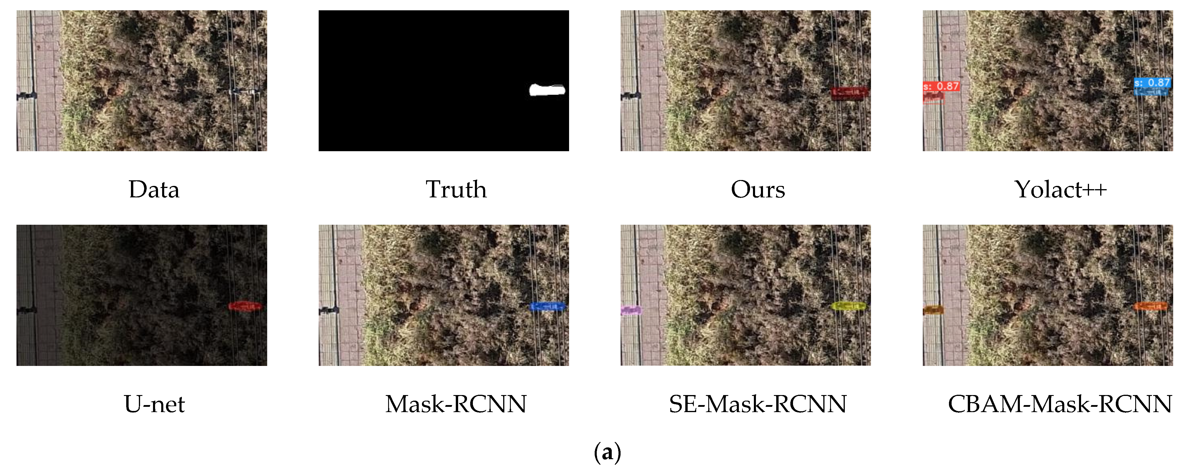
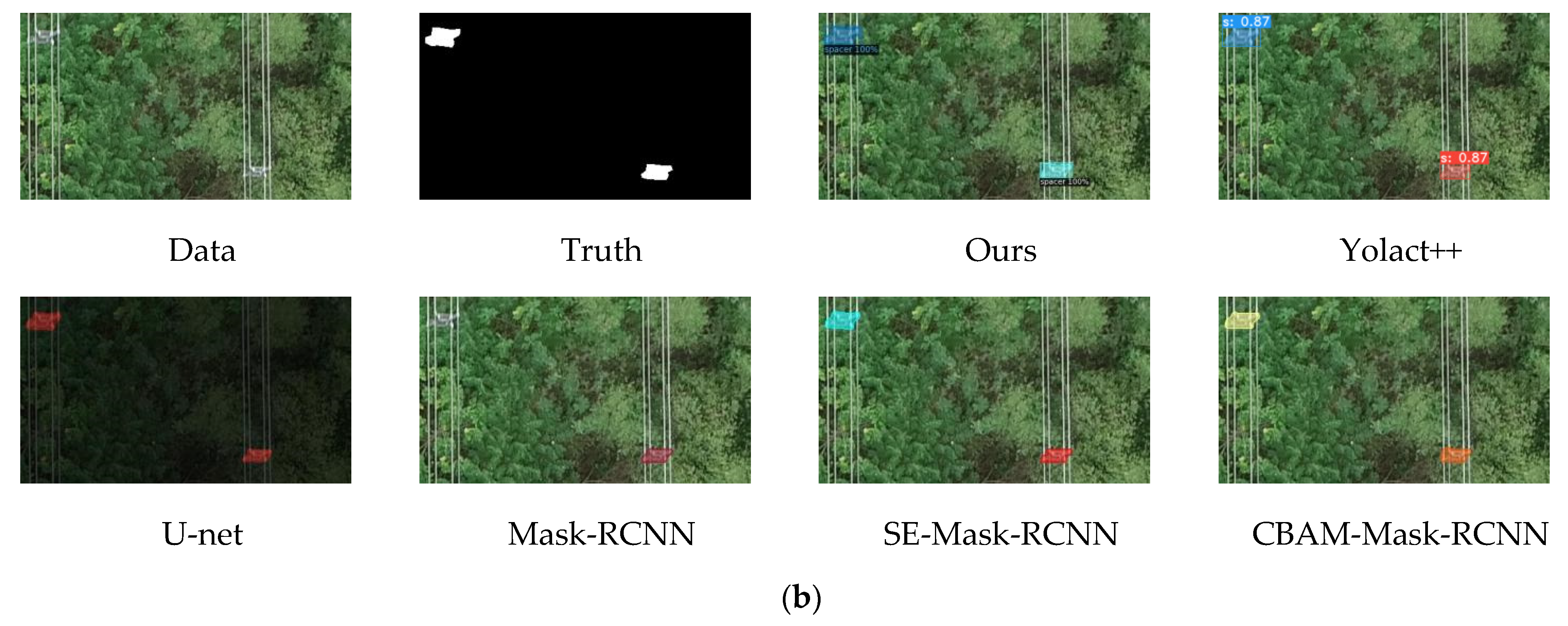
From Table 4 we can see that the best performance of the transmission line spacer bar automatic segmentation model proposed in this paper has the highest AP value of 73.399. Combined with Figure 13, we can see the performance of each model in predicting transmission line spacer bars; (a) in the group prediction results, the Yolact++, SE-Mask-RCNN, and CBAM-Mask-RCNN models all have the problem of identifying some spacer bars as complete targets, and this situation brings large errors to the subsequent work of spacer bar center coordinate extraction; (b) in the group prediction results, the Mask-RCNN model predicts only one target. Our proposed CBAM-Mask-RCNN model performed well in the prediction experiments for both sets of data.

5.4. Transmission Line Arc Sag Measurement Experiment

Ten transmission line spans of UAV aerial transmission line images are selected for arc sag measurement experiments; each transmission line span has 6–9 spacer bars, according to the transmission line spacer bar automatic segmentation model proposed in this paper to detect the spacer bars, and the center coordinates of the spacer bars are calculated; the beam method leveling algorithm and forward rendezvous algorithm are used to recover the center coordinates of the spacer bars to the 3D ground coordinates, as shown in Table 5; these points are considered as characteristic points on the transmission conductor, and combined with the spatial curve fitting algorithm to obtain the arc sag model and measure the arc sag value.
In Table 5, * indicates encrypted display of the data. Based on the ground coordinates obtained for the center of the spacer bar, we modeled the transmission lines for each stall distance. The spacer bar center coordinates were first converted to the o-xy coordinate system (as shown in Table 6).
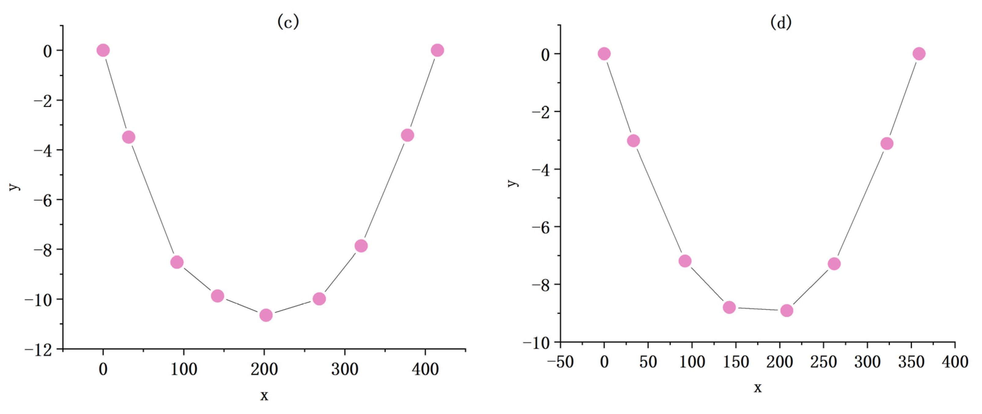
The transmission line model is established by obtaining the coordinate value of the spacer center in the o-xy coordinate system, as shown in Figure 14.
In the transmission line arc sag model, when the absolute value of y is the largest, the point is the arc sag point for this transmission line span, and the absolute value of y is the arc sag value for this transmission line span. In this paper, error and error rates are used to evaluate the accuracy of the sag values measured by this method. The calculation formula for error and error rate is as follows:
error = calculated   value true   value error   rate = error / true   value
The sag measurement results for 10 transmission line spans are shown in Table 7.
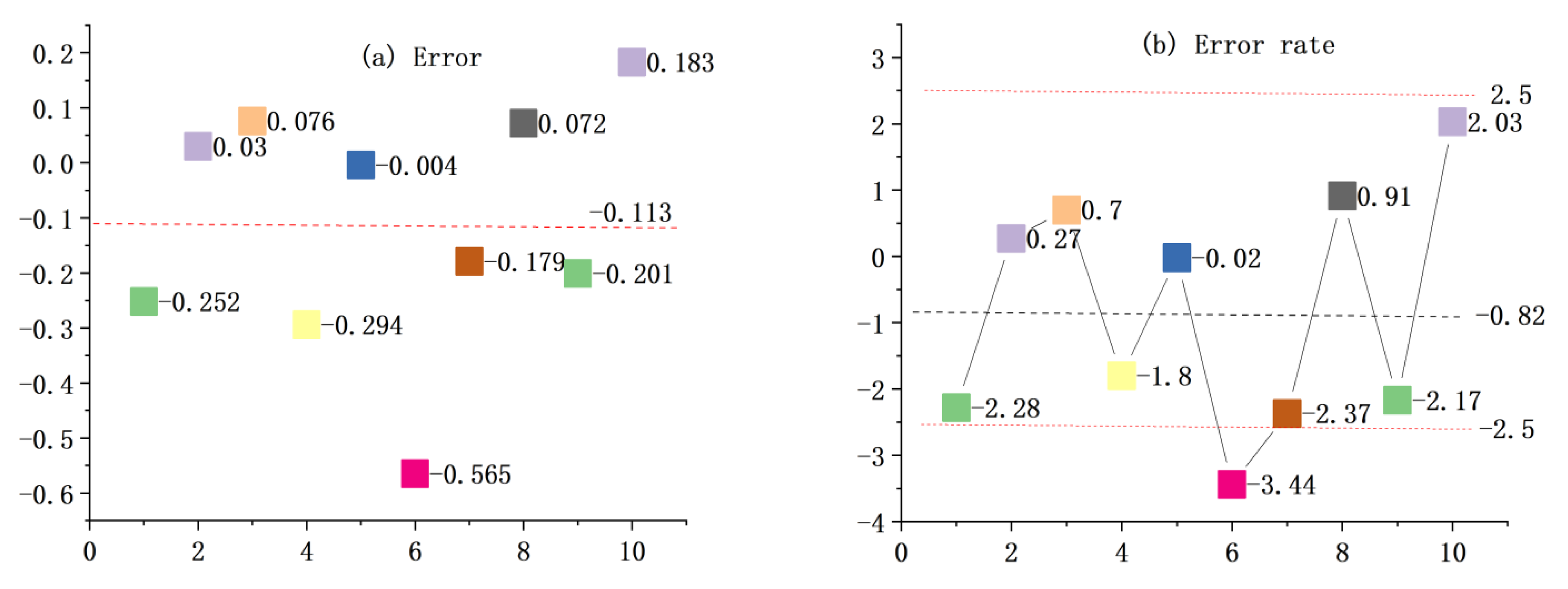
From the results in Table 7, we can see that, except for the sixth group of data, the error rate between the calculated and measured values of the algorithm is within ±2.5%, which meets the error range required by the regulations. Combined with Figure 15, we can see that the average error of the 10 groups of data is −0.113 and the average error rate is −0.82. For the sixth group of data, the error reaches −0.565 and the error rate reaches −3.44. According to analysis of the source of the error, in addition to the instrument and human operation, this may also be due to the time difference between the actual measurement and the transmission line data collection with UAV aerial photography in the two time periods. The transmission line was affected by the wind and the state changed. Additionally, when the center of the spacer bar is positioned at the edge of the image, it can result in significant errors in the calculated coordinates. This occurs because the center point is located at the very edge of the image, and the lens of the optical camera exhibits significant aberration near the edge due to mechanical processing and the main optical axis of the lens group not being perfectly aligned during installation. This results in reduced measurement accuracy of stereo pairs near the edges, which applies to both conventional measuring cameras and non-measuring cameras. To mitigate this, data is typically not collected within the 10% of the image closest to the edge, but instead obtained through adjacent stereo pairs. In the future, this issue could be addressed by adding a different camera setup or by increasing the altitude of the aerial camera appropriately. However, this transmission line arc sag measurement experiment can still reflect the effectiveness of the method of this paper.

6. Discussion

6.1. Ablation Experiments

To verify the effectiveness of the modules used in the CM-Mask-RCNN model, the following comparison experiments were performed with the same experimental parameter settings, and the experimental results are shown in Table 8.
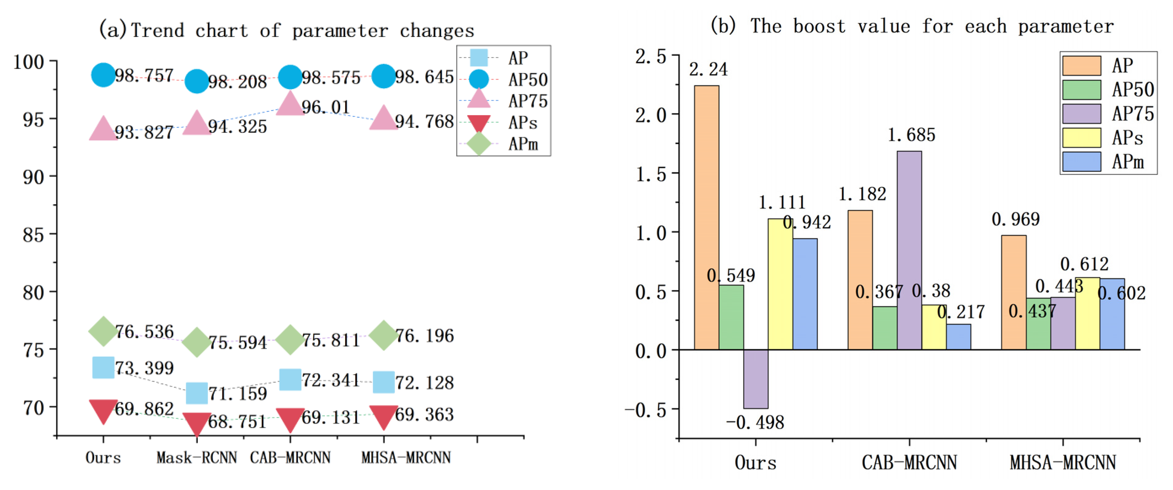
From Table 8, we can see that the performance of the model is improved by adding the CAB attention mechanism and MHSA self-attention mechanism in Mask-RCNN consecutively, but the effect of spacer bar segmentation is improved significantly when CAB and MHSA are added at the same time, which indicates that the method in this paper can pay more attention to the spacer bar region in the image and effectively improve the ability of the model to focus on the target information. Combining with Figure 16, we can see that, except for AP75, all other parameter values of this method are the maximum values, and the performance of the model is greatly improved by adding both the CAB and MHSA attention mechanisms in Mask-RCNN, in which the improvement of the AP value is as high as 2.24, reflecting that the introduction of both the CAB attention mechanism and the MHSA self-attention mechanism in this method can improve the performance of the model more comprehensively. The performance of the model is improved, especially in the case of small target extraction.

6.2. The Superiority of Combining CAB Attention Mechanism with MHSA Attention Mechanism

To verify that the CAB attention mechanism can improve the model performance more effectively in combination with MHSA than other attention mechanisms, we introduced the CBAM attention mechanism and SENet attention mechanism consecutively in combination with MHSA, the model structure of the feature extraction network was designed in line with the model structure of the method in this paper, and the superiority of the combination of the CAB attention mechanism and MHSA was verified through experiments, whose experimental results are shown in Table 9.
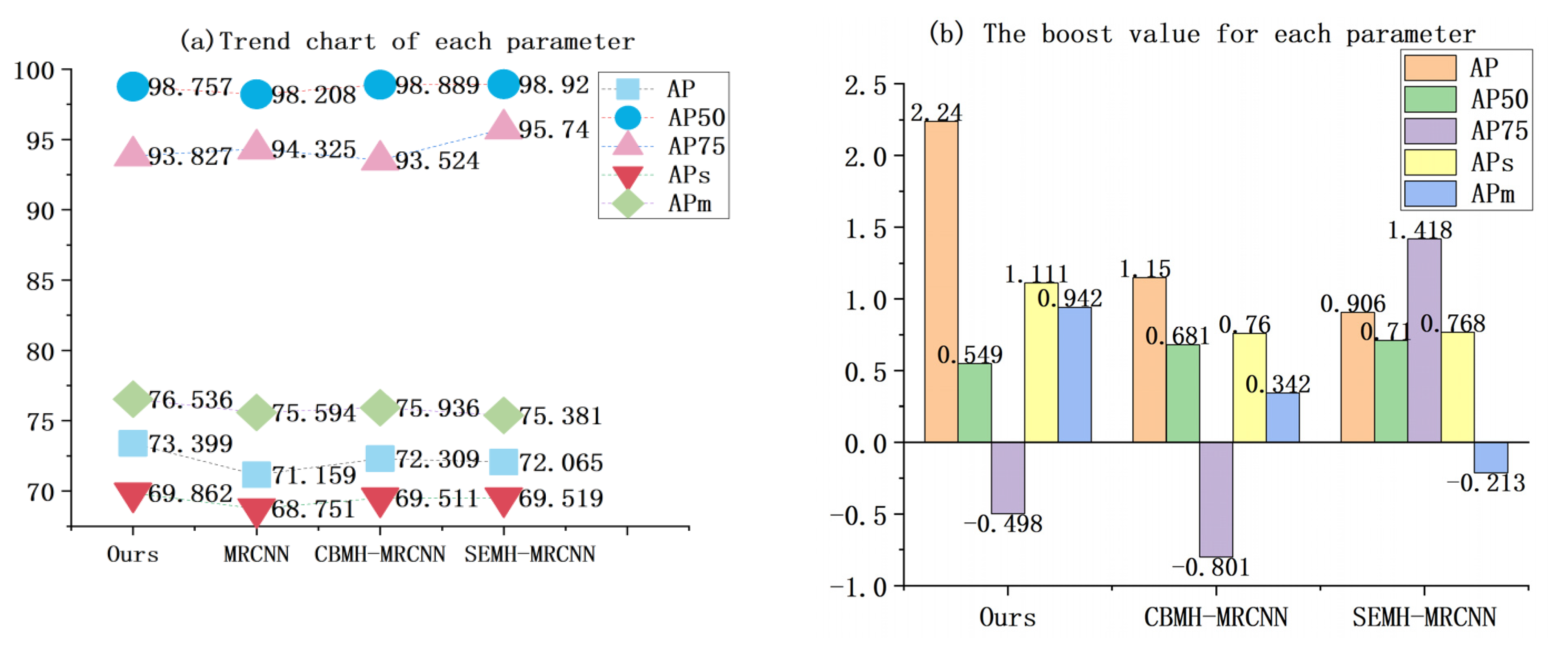
We can see from Table 9 and Figure 17 that the AP, APs, and APm of this paper’s algorithm are 73.399, 69.862, and 76.536, respectively, which are the maximum values, reflecting that this paper’s method combined with the CAB attention mechanism is more effective in improving the segmentation performance of the model than the other two methods. In addition, the AP values of all three methods improve based on Mask-RCNN, and are 2.24, 1.15, and 0.906, respectively, compared with the most obvious improvement of this paper’s method, thus further reflecting the superiority of this paper’s method using the CAB attention mechanism in combination with MHSA.

7. Conclusions

In comparison with the existing transmission line arc sag measurement method that has low efficiency, high cost, and difficulty in meeting the engineering needs of rapid inspection, this paper proposes a transmission line arc sag measurement method based on unmanned aerial photography, and the following conclusions can be obtained through experimental verification.
(1) The method proposed in this paper is based on UAV aerial photography transmission line data for arc sag measurement, which have the advantages of high efficiency, low cost, suitability for transmission line sections in harsh geographical environments, and suitability for periodic transmission line rapid inspection.
(2) The CM-Mask-RCNN spacer stick automatic segmentation algorithm proposed in this paper introduces the CAB attention mechanism and MHSA self-attention mechanism based on Mask-RCNN, which can effectively improve the segmentation performance of the model; among these improvements, the AP value is improved significantly by 2.24%.
(3) The CM-Mask-RCNN algorithm automatically segments the spacer bars and calculates the spacer bar center coordinates instead of the traditional manual marking step, which reduces manual intervention, improves the automation of the arc sag measurement, solves the traditional method’s disadvantages of low efficiency and high cost, and has high engineering application value.

Author Contributions

Conceptualization, J.S., Z.L. and Y.L.; Data curation, J.Q.; Formal analysis, J.S., J.Q. and Z.L.; Funding acquisition, Y.L. and Y.C.; Investigation, J.S., Z.L. and Y.L.; Methodology, J.S. and Y.L.; Project administration, Y.C.; Resources, Z.L. and Y.L.; Supervision, Y.J., J.G., Z.W., J.Z. and Y.C.; Validation, J.S. and J.Q.; Writing—original draft, J.S.; Writing—review & editing, J.S. and J.Z. All authors have read and agreed to the published version of the manuscript.

Funding

This research was funded by the National Key Research and Development Program of China (2018YFB0504504); the Funded Project of Fundamental Scientific Research Business Expenses of the Chinese Academy of Surveying and Mapping (AR2203); and the Overall Design of Intelligent Mapping System and Research on Several Technologies (A2201).

Data Availability Statement

The data in this study are owned by the research group and will not be transmitted.

Conflicts of Interest

The authors declare no conflict of interest.

References

  1. Ramachandran, P.; Vittal, V. On-line monitoring of sag in overhead transmission lines with leveled spans. In Proceedings of the 2006 38TH Annual North American Power Symposium, NAPS-2006 Proceedings, Carbondale, IL, USA, 17–19 September 2006; p. 405. [Google Scholar]
  2. Ren, L.; Li, H.; Liu, Y. On-line Monitoring and prediction for transmission line sag. In Proceedings of the 2012 IEEE International Conference on Condition Monitoring and Diagnosis (IEEE CMD 2012), Bali, Indonesia, 23–27 September 2012; pp. 813–817. [Google Scholar]
  3. Dong, X. Analytic Method to Calculate and Characterize the Sag and Tension of Overhead Lines. IEEE Trans. Power Deliv. 2016, 31, 2064–2071. [Google Scholar] [CrossRef]
  4. Xu, Q.; Ji, H.; Wang, M. Real-time Monitoring of Transmission Line Sag. High Volt. Technol. 2007, 176, 206–209. [Google Scholar] [CrossRef]
  5. Mensah-Bonsu, C.; Heydt, G.T. Overhead transmission conductor sag: A novel measurement technique and the relation of sag to real time circuit ratings. Electr. Power Compon. Syst. 2003, 31, 61–69. [Google Scholar] [CrossRef]
  6. Wydra, M.; Kisala, P.; Harasim, D.; Kacejko, P. Overhead Transmission Line Sag Estimation Using a Simple Optomechanical System with Chirped Fiber Bragg Gratings. Part 1: Preliminary Measurements. Sensors 2018, 18, 309. [Google Scholar] [CrossRef]
  7. Abraham, A.P.; Ashok, S. Gyro-Accelerometric SAG analysis and Online-Monitoring of Transmission Lines using Line Recon Robot. In Proceedings of the 2012 Annual IEEE India Conference (INDICON), Kochi, India, 7–9 December 2012; pp. 1036–1040. [Google Scholar]
  8. Yan, D.; Liao, Y. Online estimation of power transmission line parameters, temperature and sag. In Proceedings of the 2011 North American Power Symposium, Boston, MA, USA, 4–6 August 2011; pp. 1–6. [Google Scholar]
  9. Oleinikova, I.; Mutule, A.; Putnins, M. PMU measurements application for transmission line temperature and sag estimation algorithm development. In Proceedings of the 2014 55th International Scientific Conference on Power and Electrical Engineering of Riga Technical University (RTUCON), Riga, Latvia, 14 October 2014; pp. 181–185. [Google Scholar]
  10. Khawaja, A.H.; Huang, Q.; Li, J.; Zhang, Z. Estimation of Current and Sag in Overhead Power Transmission Lines With Optimized Magnetic Field Sensor Array Placement. IEEE Trans. Magn. 2017, 53, 2657490. [Google Scholar] [CrossRef]
  11. Sun, X.; Huang, Q.; Hou, Y.; Jiang, L.; Pong, P.W.T. Noncontact Operation-State Monitoring Technology Based on Magnetic-Field Sensing for Overhead High-Voltage Transmission Lines. IEEE Trans. Power Deliv. 2013, 28, 2145–2153. [Google Scholar] [CrossRef]
  12. Li, L.; Zhang, B.; Zhu, Y. Research on Sag Measurement System of Transmission Line Based on UAV Image and Catenary Model. Electromech. Inf. 2020, 33, 36–38. [Google Scholar] [CrossRef]
  13. Zhang, C.; Xu, Z.; Yang, S.; Liu, Z. Analysis and Application of Power Line Sag Assisted by Airborne LiDAR. Bull. Surv. Mapp. 2017, 7, 94–98+107. [Google Scholar] [CrossRef]
  14. Zhou, Y.; Guo, Q.; Mao, Q.; Zhang, S.; Kong, L.; Zhang, S.; Liu, D. Sag State Estimation of Transmission Line Based on Airborne LiDAR Data. Power Sci. Eng. 2020, 36, 58–63. [Google Scholar]
  15. Ma, W.; Wang, J.; Wang, C.; Ma, Y. Sag Simulation of Airborne Lidar Point Cloud Data Transmission Line. J. Surv. Mapp. Sci. Technol. 2019, 36, 394–399+405. [Google Scholar]
  16. Du, C.; Chen, B.; Yu, Y.; Sun, M.; Yuan, X.; Wang, Z.; Zhong, J. Transmission Line Sag Detection Method Based on 3D Model Comparison. Power Grid Clean Energy 2021, 37, 35–42+50. [Google Scholar]
  17. Sermet, M.Y.; Demir, I.; Kucuksari, S. Overhead Power Line Sag Monitoring through Augmented Reality. In Proceedings of the 2018 North American Power Symposium (NAPS), Fargo, ND, USA, 9–11 September 2018. [Google Scholar]
  18. Lu, Q.; Chen, W.; Wang, W. Research on Sag Measurement of Transmission Line Based on Aerial Image. Comput. Appl. Softw. 2019, 36, 108–111. [Google Scholar]
  19. Tong, W.; Li, B.; Yuan, J.; Zhao, S. Sag Measurement Method of Transmission Line Based on Aerial Sequence Image. Chin. J. Electr. Eng. 2011, 31, 115–120. [Google Scholar] [CrossRef]
  20. Wang, L.; Shao, F.; Xiao, B. Transmission Line Sag Measurement Method Based on Binocular Vision Sparse Point Cloud Reconstruction. J. Taiyuan Univ. Technol. 2016, 47, 747–751+785. [Google Scholar] [CrossRef]
  21. Li, J. Sag Measurement of Transmission Line Based on Computer Vision. Master’s Thesis, North China Electric Power University (Hebei), Beijing, China, 2009. [Google Scholar]
  22. Hou, Q.; Zhou, D.; Feng, J. Coordinate Attention for Efficient Mobile Network Design. In Proceedings of the 2021 IEEE/CVF Conference on Computer Vision and Pattern Recognition, CVPR 2021, Nashville, TN, USA, 20–25 June 2021; pp. 13708–13717. [Google Scholar]
  23. Xie, C.; Zhu, H.; Fei, Y. Deep coordinate attention network for single image super-resolution. IET Image Process. 2022, 16, 273–284. [Google Scholar] [CrossRef]
  24. Zhang, J.; Wang, K.; He, Y.; Kuang, L. Visual Object Tracking via Cascaded RPN Fusion and Coordinate Attention. CMES-Comput. Model. Eng. Sci. 2022, 132, 909–927. [Google Scholar] [CrossRef]
  25. Chang, X.; Zhang, Y.; Yang, L.; Kou, J.; Wang, X.; Xu, D. Speech enhancement method based on the multi-head self-attention mechanism. J. Xidian Univ. 2020, 47, 104–110. [Google Scholar]
  26. Guo, Q.; Huang, J.; Xiong, N.; Wang, P. MS-Pointer Network: Abstractive Text Summary Based on Multi-Head Self-Attention. IEEE Access 2019, 7, 138603–138613. [Google Scholar] [CrossRef]
  27. Jin, Y.; Tang, C.; Liu, Q.; Wang, Y. Multi-Head Self-Attention-Based Deep Clustering for Single-Channel Speech Separation. IEEE Access 2020, 8, 100013–100021. [Google Scholar] [CrossRef]
  28. Chang, C.-C.; Wang, Y.-P.; Cheng, S.-C. Fish Segmentation in Sonar Images by Mask R-CNN on Feature Maps of Conditional Random Fields. Sensors 2021, 21, 7625. [Google Scholar] [CrossRef]
  29. Degawa, N.; Lu, X.; Kimura, A. A performance improvement of Mask R-CNN using region proposal expansion. In Proceedings of the International Workshop on Advanced Image Technology (IWAIT) 2019, Singapore, 6–9 January 2019. [Google Scholar]
  30. He, K.; Gkioxari, G.; Dollár, P.; Girshick, R. Mask R-CNN. In Proceedings of the 2017 IEEE International Conference on Computer Vision (ICCV), Venice, Italy, 22–29 October 2017; pp. 2980–2988. [Google Scholar]
  31. Ren, S.; He, K.; Girshick, R.; Sun, J. Faster R-CNN: Towards Real-Time Object Detection with Region Proposal Networks. IEEE Trans. Pattern Anal. Mach. Intell. 2017, 39, 1137–1149. [Google Scholar] [CrossRef]
  32. Chen, H.; Yu, X. The Segmentation Algorithm of Marine Warship Image Based on Mask RCNN. In Proceedings of the Twelfth International Conference on Signal Processing Systems, Shanghai, China, 6–9 November 2021. [Google Scholar]
  33. Gong, Y.; Yu, X.; Ding, Y.; Peng, X.; Zhao, J.; Han, Z. Effective Fusion Factor in FPN for Tiny Object Detection. In Proceedings of the 2021 IEEE Winter Conference on Applications of Computer Vision (WACV 2021), Waikoloa, HI, USA, 3–8 January 2021; pp. 1159–1167. [Google Scholar]
  34. Li, X.; Liu, G.; Qiao, D. Application of Improved Mask RCNN in Offshore Ship Instance Segmentation. Ship Eng. 2021, 43, 166–171. [Google Scholar]
  35. Yang, C.; Wu, Z.; Zhou, B.; Lin, S. Instance Localization for Self-supervised Detection Pretraining. In Proceedings of the 2021 IEEE/CVF Conference on Computer Vision and Pattern Recognition, CVPR 2021, Nashville, TN, USA, 20–25 June 2021; pp. 3986–3995. [Google Scholar]
  36. Krueangsai, A.; Supratid, S. Effects of Shortcut-Level Amount in Lightweight ResNet of ResNet on Object Recognition with Distinct Number of Categories. In Proceedings of the 2022 International Electrical Engineering Congress (iEECON), Khon Kaen, Thailand, 9–11 March 2022; pp. 1–4. [Google Scholar]
  37. Li, B.; He, Y. An Improved ResNet Based on the Adjustable Shortcut Connections. IEEE Access 2018, 6, 18967–18974. [Google Scholar] [CrossRef]
  38. Zhou, T.; Huo, B.; Lu, H.; Ren, H. Research on Residual Neural Network and Its Application on Medical Image Processing. Acta Electron. Sin. 2020, 48, 1436–1447. [Google Scholar]
  39. Lin, T.Y.; Dollár, P.; Girshick, R.; He, K.; Hariharan, B.; Belongie, S. Feature Pyramid Networks for Object Detection. In Proceedings of the 2017 IEEE Conference on Computer Vision and Pattern Recognition (CVPR), Honolulu, HI, USA, 21–26 July 2017; pp. 936–944. [Google Scholar]
  40. Liu, X.; Pan, H.; Li, X. Object detection for rotated and densely arranged objects in aerial images using path aggregated feature pyramid networks. In Proceedings of the MIPPR 2019: Pattern Recognition and Computer Vision, Wuhan, China, 2–3 November 2020. [Google Scholar]
  41. Wu, Y.; Tang, S.; Zhang, S.; Ogai, H. An Enhanced Feature Pyramid Object Detection Network for Autonomous Driving. Appl. Sci. 2019, 9, 4363. [Google Scholar] [CrossRef]
  42. Bolya, D.; Zhou, C.; Xiao, F.; Lee, Y.J. YOLACT++ Better Real-Time Instance Segmentation. IEEE Trans. Pattern Anal. Mach. Intell. 2022, 44, 1108–1121. [Google Scholar] [CrossRef]
  43. Wang, J.; Zhuang, W.; Shang, D. Light Enhancement Algorithm Optimization for Autonomous Driving Vision in Night Scenes based on YOLACT++. In Proceedings of the 2022 3rd International Conference on Information Science, Parallel and Distributed Systems (ISPDS), Guangzhou, China, 22–24 July 2022; pp. 417–423. [Google Scholar]
  44. Alom, M.Z.; Yakopcic, C.; Hasan, M.; Taha, T.M.; Asari, V.K. Recurrent residual U-Net for medical image segmentation. J. Med. Imaging 2019, 6, 014006. [Google Scholar] [CrossRef]
  45. Chen, K.; Xu, G.; Qian, J.; Ren, C.-X. A Bypass-Based U-Net for Medical Image Segmentation. In Proceedings of the Intelligence Science and Big Data Engineering: Visual Data Engineering, PT I, Nanjing, China, 17–20 October 2019; pp. 155–164. [Google Scholar]
  46. Siddique, N.; Paheding, S.; Elkin, C.P.; Devabhaktuni, V. U-Net and Its Variants for Medical Image Segmentation: A Review of Theory and Applications. IEEE Access 2021, 9, 82031–82057. [Google Scholar] [CrossRef]
  47. Hu, J.; Shen, L.; Sun, G. Squeeze-and-Excitation Networks. In Proceedings of the 2018 IEEE/CVF Conference on Computer Vision and Pattern Recognition, Salt Lake City, UT, USA, 18–23 June 2018; pp. 7132–7141. [Google Scholar]
  48. Lyu, Z.; Xu, X.; Zhang, F. Lightweight attention mechanism module based on squeeze and excitation. J. Comput. Appl. 2022, 42, 2353–2360. [Google Scholar]
  49. Ovalle-Magallanes, E.; Gabriel Avina-Cervantes, J.; Cruz-Aceves, I.; Ruiz-Pinales, J. LRSE-Net: Lightweight Residual Squeeze-and-Excitation Network for Stenosis Detection in X-ray Coronary Angiography. Electronics 2022, 11, 3570. [Google Scholar] [CrossRef]
  50. Wang, C.; Li, B.; Jiao, B.; Liang, Y.; Cheng, P. Convolutional Block Attention Module (CBAM)-Based Convolutional Neural Network Rolling Bearing Fault Diagnosis Method, Involves Inputting Detected Rolling Bearing Data Set to Trained CBAM-Based Network to Output Fault Diagnosis Result. CN111458148-A, 28 July 2020. [Google Scholar]
  51. Woo, S.; Park, J.; Lee, J.-Y.; Kweon, I.S. CBAM: Convolutional Block Attention Module. In Proceedings of the Computer Vision–ECCV 2018, PT VII, Munich, Germany, 8–14 September 2018; pp. 3–19. [Google Scholar]
  52. Xiang, L.; Zhou, Z.; Miao, L.; Chen, Q. Signal Recognition Method of X-ray Pulsar Based on CNN and Attention Module CBAM. In Proceedings of the 33rd Chinese Control and Decision Conference (CCDC 2021), Kunming, China, 22–24 May 2021; pp. 5436–5441. [Google Scholar]
Figure 1. Overview of survey area.
Remotesensing 15 02533 g001
Figure 2. Structure of CM-Mask-RCNN.
Remotesensing 15 02533 g002
Figure 3. Structure of Mask-RCNN.
Remotesensing 15 02533 g003
Figure 4. The details of the coordinate attention block.
Remotesensing 15 02533 g004
Figure 5. MHSA block schematic.
Remotesensing 15 02533 g005
Figure 6. Bottleneck after adding MHSA.
Remotesensing 15 02533 g006
Figure 7. Arc sag measurement technical route.
Remotesensing 15 02533 g007
Figure 8. Flowchart of CM-Mask-RCNN extracting spacer bar center coordinates.
Remotesensing 15 02533 g008
Figure 9. Technical process for recovering 3D information of spacer center.
Remotesensing 15 02533 g009
Figure 10. Principle of stereo image to space front rendezvous.
Remotesensing 15 02533 g010
Figure 11. Sag in a span.
Remotesensing 15 02533 g011
Figure 12. This is an example dataset diagram. (a) Image background shows sidewalk. (b) Image background shows road. (c) Image background shows bushes. (d) Image background shows grass.
Remotesensing 15 02533 g012
Figure 13. Comparison of some results of transmission line spacer bars predicted by each model. (a,b) show the prediction result plots for two different image backgrounds, each with eight plots for the test set image (Data), the truth image (Truth), and the prediction results of six methods (Ours, Yolact++, U-Net, Mask-RCNN, SE-Mask-RCNN, and CBAM-Mask-RCNN, respectively).
Remotesensing 15 02533 g013aRemotesensing 15 02533 g013b
Figure 14. Transmission line model with partial span. (ad) are transmission line models numbered 1, 2, 3, and 10, respectively.
Remotesensing 15 02533 g014aRemotesensing 15 02533 g014b
Figure 15. Trend graph of distance error and error rate for each dataset. (a) is error distribution graph; (b) is trend graph of error rate change.
Remotesensing 15 02533 g015
Figure 16. Variation of segmentation performance parameters by method. (a) is trend graph of split performance parameters; (b) is the variation values of each segmentation performance parameter for each method.
Remotesensing 15 02533 g016
Figure 17. Variation of segmentation performance parameters by method. (a) is trend graph of split performance parameters; (b) is the variation values of each segmentation performance parameter for each method.
Remotesensing 15 02533 g017
Table 1. UAV parameters.
Camera, GNSSParameters
Image sensor2048 million total pixels
Video resolution4K: 3840 × 2160
Maximum photo resolution5472 × 3078 (16:9)
4864 × 3648 (4:3)
5472 × 3648 (3:2)
Hovering accuracyWhen RTK is enabled and RTK is working normally.
Vertical: ±0.1 m; Horizontal: ±0.1 m
Without RTK enabled.
Vertical: ±0.1 m (when visual positioning is working properly)
±0.5 m (when GNSS positioning is working properly)
Horizontal: ±0.3 m (when visual positioning is working properly)
±1.5 m (when GNSS positioning is working properly)
Positioning accuracyVertical: 1.5 cm + 1 ppm (RMS)
Horizontal: 1 cm + 1 ppm (RMS)
Table 2. Internal orientation parameters and distortion parameters of the lens.
NumCameraLens Distortion ParametersInterior Orientation Element
Radial DistortionTangential DistortionNon-Square Correction FactorImage Main Point and Focal Length (pixels)
k1k2p1p2abx0y0f
1Phantom 4 RTK1.06 × 10−9−9.60 × 10−173.23 × 10−79.19 × 10−7−3.42 × 10⁻⁶−0.000271911.8671055.7822668.048
Table 3. Training parameters.
ParameterValue
weight decay0.0001
lr0.001
Max-iteration36,000
ims_per_batch4
Batch_size_per_image128
Table 4. Comparison of test results of different models on transmission line spacer dataset.
MethodAP
Ours73.399
Yolact++71.081
U-net71.352
MRCNN71.159
SE-MRCNN72.299
CBAM-MRCNN72.441
Table 5. Three-dimensional coordinates of characteristic points.
NumP-numXYZ
1A**7818.455**67,936.626781.100
1**7843.433**67,957.120778.112
2**7889.561**67,994.134774.038
3**7929.365**68,026.084773.759
4**7975.983**68,063.355773.138
5**8027.400**68,104.606774.481
6**8068.621**68,137.530777.582
7**8113.931**68,173.788782.366
B**8142.398**68,196.196786.410
...............
10A**1688.332**71,433.326783.372
1**1687.413**71,466.734781.056
2**1685.257**71,525.498778.137
3**1683.751**71,576.037777.594
4**1681.730**71,641.541778.871
5**1680.008**71,695.496781.641
6**1678.343**71,755.476787.08
B**1677.107**71,791.992790.971
Table 6. Coordinates of feature points in the o-xy coordinate system.
NumP-numxy
1A00
132.2547−3.4008
291.3517−8.2311
3142.3831−9.9629
4202.0574−10.5473
5267.9887−10.0476
6320.7794−7.6216
7378.8667−3.5803
B415.14260
10A00
133.3502−3.0228
292.0913−7.1864
3142.6291−8.7997
4208.1781−8.9105
5262.2067−7.284
6322.3114−3.1166
B358.92270
Table 7. Experimental results of arc sag measurement.
NumCalculated Values/mTrue Value/mError/mError Rate/%
110.78111.033−0.252−2.28
211.04111.0110.030.27
310.88410.8080.0760.70
416.0516.344−0.294−1.80
516.76416.768−0.004−0.02
615.87616.441−0.565−3.44
77.3787.557−0.179−2.37
87.9857.9130.0720.91
99.059.251−0.201−2.17
109.2089.0250.1832.03
Table 8. Comparison of ablation test results.
MethodAPAP50AP75APsAPm
Ours73.39998.75793.82769.86276.536
MRCNN71.15998.20894.32568.75175.594
CAB-MRCNN72.34198.57596.01069.13175.811
MHSA-MRCNN72.12898.64594.76869.36376.196
Table 9. Comparison of experimental results of each attention mechanism combined with MHSA.
MethodAPAP50AP75APsAPm
Ours73.39998.75793.82769.86276.536
Mask-RCNN71.15998.20894.32568.75175.594
CBMH-MRCNN72.30998.88993.52469.51175.936
SEMH-MRCNN72.06598.92095.74369.51975.381
Disclaimer/Publisher’s Note: The statements, opinions and data contained in all publications are solely those of the individual author(s) and contributor(s) and not of MDPI and/or the editor(s). MDPI and/or the editor(s) disclaim responsibility for any injury to people or property resulting from any ideas, methods, instructions or products referred to in the content.