Abstract
The increasing number of flood events combined with coastal urbanization has contributed to significant economic losses and damage to buildings and infrastructure. Development of higher resolution SAR flood mapping that accurately identifies flood features at all scales can be incorporated into operational flood forecasting tools, improving response and resilience to large flood events. Here, we present a comparison of several methods for characterizing flood inundation using a combination of synthetic aperture radar (SAR) remote sensing data and machine learning methods. We implement two applications with SAR GRD data, an amplitude thresholding technique applied, for the first time, to Sentinel-1A/B SAR data, and a machine learning technique, DeepLabv3+. We also apply DeepLabv3+ to a false color RGB characterization of dual polarization SAR data. Analyses at 10 m pixel spacing are performed for the major flood event associated with Hurricane Harvey and associated inundation in Houston, TX in August of 2017. We compare these results with high-resolution aerial optical images over this time period, acquired by the NOAA Remote Sensing Division. We compare the results with NDWI produced from Sentinel-2 images, also at 10 m pixel spacing, and statistical testing suggests that the amplitude thresholding technique is the most effective, although the machine learning analysis is successful at reproducing the inundation shape and extent. These results demonstrate the effectiveness of flood inundation mapping at unprecedented resolutions and its potential for use in operational emergency hazard response to large flood events.
1. Introduction
Flooding is one of the most frequent hydro-meteorological hazards, with annual losses totaling approximately $10 billion (USD) [1], and average losses are expected to increase to more than $1 trillion annually by 2050 [2]. In 2004, it was estimated that more than half a billion people are impacted every year worldwide. That number could double by 2050 [3]. It is anticipated that increasing populations, regional subsidence, and climate change will exacerbate both annual flooding and extreme events, particularly in large coastal cities [4]. Improved remote sensing instrumentation and analysis will be critical tools in the assessment of flood risk through improved characterization of flood inundation, providing insights into the dynamics of coastal and riverine water bodies, their incorporation into flood models, and improved flood risk mapping, impact assessments, forecasting, alerting, and emergency response systems.
Accurate information about impending and ongoing hazards is critical to aid effective preparation and subsequent response to reduce the impact of large flood events [5,6,7]. Technological advancements have enabled rapid dissemination of hazard information via mobile communication and social networking [8,9]. DisasterAWARE®, a platform operated by the Pacific Disaster Centre (PDC), provides warning and situational awareness information support through mobile apps and web-based platforms to millions of users worldwide for multiple hazards. DisasterAWARE® is developing a component that will integrate high-resolution SAR images of flood extent and inundation depth into hydrological models of flood forecasting and impact assessment.
Due to the extensive cloud cover during large precipitation events, flood mapping offers particular challenges for many types of remote sensing. For example, while optical satellite imagery such as that from Landsat or the Moderate Resolution Imaging Spectroradiometer (MODIS) has been successfully employed to derive flood inundation maps [10,11,12,13], their operational effectiveness can be limited by extended periods of precipitation and cloud cover. However, because SAR is an all-weather collection system that sees through clouds, it is extremely useful for real-time, or near real-time, flood mapping [14]. For the purposes of flood mapping, real-time flood mapping would produce images as flood water rose, approximately daily or even hourly. Because SAR satellites that produce freely available images today operate with repeat times of 6-to-12 days, SAR near real-time flood mapping often is limited to a few days into the flood event.
A variety of satellite SAR images have been used for water surface detection [15,16,17,18,19,20], including X-band (COSMO-SkyMed, TerraSAR-X), L-band (ALOS PALSAR), and C-band (RADARSAT-1/2, ENVISAT ASAR, Sentinel-1A/B) sensors. Additional applications include flood depth estimation [21,22,23] and flooding beneath vegetation [24,25,26,27]. SAR-based flood extent mapping algorithms broadly include visual interpretation [28,29], supervised classification and image texture methods [14,30,31,32], active contour modeling [33,34], multitemporal change detection methods [35,36], and histogram thresholding [37,38]. Histogram thresholding relies on the ability to separate inundated from non-flooded areas over large areas based the specular backscattering of active radar pulses on smooth water surfaces and the resultant low intensity of the signal return. Here, we present research aimed at improving the resolution and accuracy of those SAR images of flood extent.
In this work, we compare advanced methods for discriminating between land and water pixels at spatial resolutions of 10 m, using ground range detected (GRD) data imagery from the European Space Agency (ESA) Sentinel-1A/B C-band SAR satellite. We apply an amplitude thresholding algorithm to identify inundation using SAR data to flooding associated with Hurricane Harvey (Harvey). Harvey, a slow-moving Category 4 event, struck the Houston, TX, region on 26 August 2017. We also implemented a machine learning (ML) algorithm, DeepLabv3+, to increase image quality and improve identification of water pixels. We present the results from applying DeepLabv3+ to both the original SAR GRD data and to the results of applying a false RGB classification scheme using the different SAR polarizations.
2. Materials and Methods
In this work, we apply two different methods to SAR GRD data with a pixel spacing of 10 m, to produce flood inundation maps at 10 m resolution. The first is a thresholding technique [37,38], while the second is based on an RGB classification scheme [31]. We also apply a machine learning technique, DeepLabv3+, to the same GRD data and to the classification outputs. All analyses are applied to SAR GRD data with 10 m pixel spacing, and the results are decimated to 10 m spacing. We use both the Normalized Difference Water Index (NDWI) estimated from ESA’s Sentinel-2 optical images and the NOAA data to validate the results.
2.1. Data
For this study, we downloaded high-resolution ground range detected (GRD) images from ESA’s Sentinel-1A/B satellite (C-band SAR, IW mode) with a 6–12 day repeat time. Images were downloaded from the National Aeronautics and Space Administration’s (NASA) Alaska Satellite Facility Distributed Active Archive Center (ASFDAAC) (https://search.asf.alaska.edu/ (accessed on 9 June 2021)). Here, we downloaded GRD images at 10 m resolution for 29 August 2017. Figure 1 shows the Houston, TX, study area and the footprints of the Sentinel-1 and Sentinel-2 scenes used in this study. The northern SAR image is from Path 34, Frame 95, and the southern SAR scene is from Path 34, Frame 90.
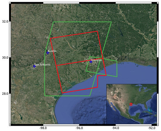
Figure 1.
Map of study area. Red squares outline of the two ascending SAR images used in this analysis, 29 August 2017. The northern SAR image is Path 34, Frame 95, and the southern SAR scene is Path 34, Frame 90. The Sentinel-2 scenes are outlined in green; the large swath was acquired on 30 August 2017, and the smaller scene on 1 September 2017.
Additionally, we preprocess the GRD product into a σ0 (sigma nought) product using the Sentinel-1 Toolbox Command Line Tool [39]. σ0 is the backscatter coefficient, the normalized measure of the radar return from a distributed target per unit area on the ground.
This preprocessing consists of the following algorithms attached to the Sentinel-1 Toolbox: Apply Orbit File, Remove GRD Border Noise, Calibration, Speckle Filter, and Terrain Correction. In the Calibration step, we derive the σ0 band [40]. Thus, we call the final, preprocessed product the σ0 SAR image.
The National Oceanic and Atmospheric Administration (NOAA) acquired aerial optical imagery of the region to support emergency response activities after the hurricane. The NOAA Remote Sensing Division acquired airborne digital optical imagery of the Houston area between 27 August and 3 September 2017, in response to Hurricane Harvey. The images were acquired from an altitude between 2500 to 5000 feet using a Trimble Digital Sensor System (DSS). Individual images were combined into a mosaic and tiled for distribution (Figure 2). Approximate ground sample distance (GSD) for each pixel is between 35 and 50 cm (https://storms.ngs.noaa.gov/storms/harvey/download/metadata.html (accessed on 1 February 2021)). These data were used to identify flooded polygons for ground truthing of our results.
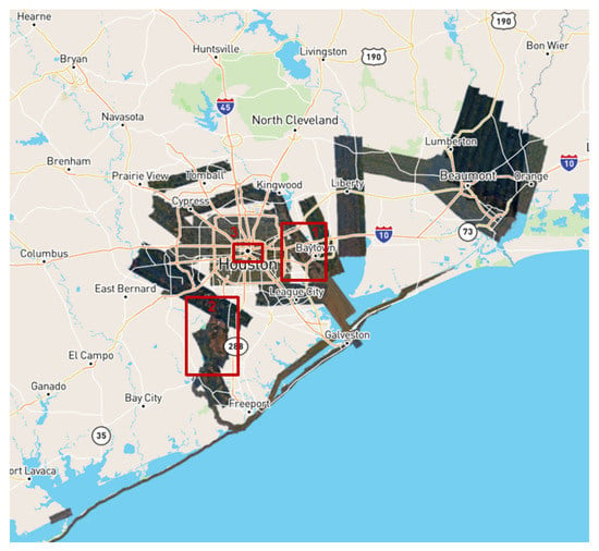
Figure 2.
NOAA Remote Sensing Division airborne digital optical imagery of the Houston area acquired between 27 August and 3 September 2017, in response to Hurricane Harvey. Approximate GSD for each pixel ranges between 35 and 50 cm (https://storms.ngs.noaa.gov/storms/harvey/download/metadata.html (accessed on 1 February 2021)). Red squares outline three areas selected for comparison with results of flood detection and DeepLabv3+ analysis.
The Dartmouth Flood Observatory (DFO) provides detailed information on flood inundation for global event in recent decades, largely derived from satellite data, and includes an “Active Archive of Large Flood Events, 1985–present”. Collection of these data has been carried out by G. R. Brakenridge and co-workers, first at Dartmouth College and then at the University of Colorado Boulder [41]; http://floodobservatory.colorado.edu (accessed on 22 February 2021). For this event, DFO flood estimates are derived from NASA MODIS, ESA Sentinel-1, Cosmo SkyMed, and Radarsat2 satellite data. Here, we use the DFO MODIS data, at 250 m pixel spacing.
Figure 3a shows the global water mask (GWM), derived from the Global Surface Water map [42], where blue is permanent water. Figure 3b shows the MODIS-derived DFO water map for flooding from Hurricane Harvey at pixel spacing of 250 m, 28 August–4 September 2017 [41].
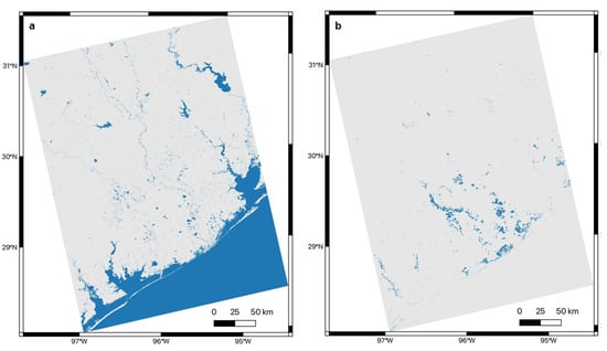
Figure 3.
(a) GWM (water pixels in blue) [https://global-surface-water.appspot.com/download (accessed on 17 May 2021)]; (b) MODIS-derived flood inundation, 250 m pixel spacing, for 28 August–4 September 2017, courtesy of DFO (water in blue) [41], with the GWM removed to characterize temporary water only.
For our analysis of the NDWI of this time, we acquired two Sentinel-2 scenes. We selected the two best Sentinel-2 scenes that are the closest in time to our SAR scene (footprints shown in Figure 1). The first scene is a large swath from 30 August 2017, and the second scene is a smaller swath from 1 September 2017, as shown in Figure 1. Since our SAR data were acquired on 29 August 2017, this gives a time difference of 1 and 3 days respectively between the Sentinel-2 images and the Sentinel-1 images from 29 August 2017. We obtained 37 Sentinel-2 images from the GEE platform [43], 31 acquired on 30 August 2017, and 6 acquired on 1 September 2017.
2.2. Methods
Methods most commonly applied to the detection of inundation include automatic histogram thresholding-based methods [37,38], multitemporal change detection-based methods [44,45], and machine learning and neural network methods [46,47,48]. Here, we implement both a thresholding technique and a false RGB classification scheme [31].
2.2.1. NDWI Analysis
For additional comparison with our results, we estimated the Normalized Difference Water Index (NDWI) on multispectral Sentinel-2 imagery over Houston [49]. Using Google Earth Engine [43], we extracted the B03 band and B08 band only from the Sentinel-2 MSI Level-1C products, 10 m pixel spacing. These bands correspond to the wavelength of green and near-infrared (NIR) light, respectively.
The majority of the Sentinel-1 area is covered by the large Sentinel-2 swath, as it encompasses a larger area. Unfortunately, a large cloud inhabits the northeast corner of this image. To combat this, we use the smaller Sentinel-2 swath to fill in some of the area in the northeast. Both images have smaller clouds present, but the calculation of NDWI should mask out these clouds sufficiently for accurate comparison.
The NDWI equation is given by
(GREEN − NIR)/(GREEN + NIR).
The result is an image with values in the range [−1, 1]. To achieve a ground truth binary classification of water pixels and non-water pixels, we must select a threshold value to make this distinction. According to [49], positive values are determined to be open water, although others have suggested that manually choosing a threshold leads to higher accuracy in classifying water [50]. However, we opted for the threshold of 0, as in [49], for simplicity and to avoid any potential bias incurred in a manual decision.
We then stitch the two resulting NDWI images together and crop and resample to match the resolution and bounds of the SAR data. The resulting NDWI map is shown in Figure 4.
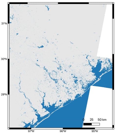
Figure 4.
NDWI derived from Sentinel-2 images, acquired on 30 August and 1 September 2017. Water is shown in blue, and pixel spacing is 10 m.
2.2.2. SAR Water Detection
Thresholding
The first method applied to SAR images in this study of Hurricane Harvey flooding was a thresholding technique applied to map inundated regions based on the low backscatter coefficient of the GRD SAR data. The distribution of SAR amplitudes, with the appropriate power transform, is a bimodal Gaussian distribution that can be used to separate water and non-water pixels [37]. This characteristic can be exploited to automatically identify a threshold of the pixel values to classify inundated areas.
The SAR image is subdivided into tiles, due to the wide SAR swath. The maximum normalized between-class variance (BCV) is used to identify those pixels within each tile that have a bimodal distribution [37,51]. From simulations, a distribution can be assumed bimodal for a maximum value of BCV greater than 0.65 [37,38]. Each tile is further split into an array of s x s pixels, where the value of s is varied to determine an optimal threshold for each tile. Bimodal pixels are identified, and an automatic threshold is selected from either the local minimum (LM) separating the peaks in the bimodal distribution or the mode of the distribution itself. Finally, the threshold for the entire tile is equal to the mean of all the thresholds for every subset of s x s pixels. We repeat this process for every tile to generate a binary output that identifies the pixels classified as water. Note that this method also classifies permanent water bodies, in addition to transient flooded pixels, so that, for flood hazard characterization, it is necessary to take into account the common classifications in all images using an earlier set of images, assuming sufficient temporal coverage, or the Global Surface Water map [42]; https://global-surface-water.appspot.com/download (accessed on 17 May 2021). This method also can be applied to VV (vertical-vertical) and VH (vertical-horizontal) SAR polarizations, separately or jointly, to improve accuracy.
RGB Classification
We also implemented an RGB classification scheme, providing an additional data set for input into the machine learning algorithm using the same SAR images. In this application, dual-polarization SAR images, VV and VH, are used to construct a false color RGB image [44]. We leverage the dual-polarization of Sentinel-1 GRD products to construct a similar 3-channel image using the σ0 SAR images from the SNAP pre-processing above. We designate the channels as colors (red, green, and blue), but it is important to note that colors do not represent the same physical features as that of an optical image. In the RGB composite here, the VH band is assigned to the red channel, the VV band is assigned to the green channel, and the ratio of VH to VV (VH/VV) is assigned to the blue channel.
The following steps are necessary to transform the data before constructing the RGB composite. First, pixel values are converted from a linear scale to a decibel scale, as in [44]:
Here, σ0 denotes the σ0 SAR image. Then, the ratio of the VH polarization to the VV polarization is computed. To prevent numerical instability, VH/VV = 0 when VV = 0. We then perform quantile clipping to diminish the effect of outliers or extremely bright scatterers. To accomplish this, we find the 99th percentile of each band and set all values above the 99th percentile equal to the value at 99th percentile. Use of the 99th percentile was chosen empirically because it reduced the outliers enough with minimal change in the pixel distribution. Finally, all three bands are mapped to the interval [0, 1]
Figure 5a shows the original σ0 SAR image, while Figure 4b is the false color RGB image derived from the image in Figure 4a, where VH is blue, VV is green, and VH/VV is blue.
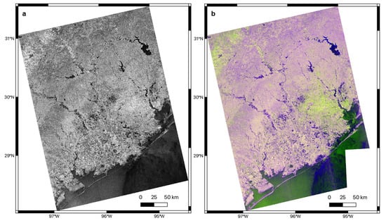
Figure 5.
(a) Sentinel-1 SAR image, 29 August 2017, 10 m pixel spacing; (b) false color RGB image, where VH is blue, VV is green, and VH/VV is blue, 10 m pixel spacing.
2.2.3. Machine Learning and DeepLabV3+
The goal of this phase of the project is to train a machine learning model to detect differences between pixels in our SAR scenes and attribute these changes to inundation, which is captured in the machine learning model after the model has been well trained. We first identified a training data set by identifying flooded pixels on the SAR GRD image from 29 August 2017, as shown in Figure 6 [52,53]. Here, we apply DeepLabv3+ [54], an encoder–decoder structure used in deep neural networks for semantic segmentation tasks, to the SAR GRD image shown in Figure 6.
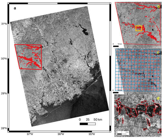
Figure 6.
(a) SAR GRD image of Houston, TX, 29 August 2017, with training region and polygons outlined in red; (b) training polygons from (a); (c) grids for manually drawing flooding areas; and (d) enlarged training polygons marked by the orange box in (b).
We chose a training region (Figure 6a) and manually delineated all flooded areas within it by the guidance of grids (Figure 6b,c) and obtained 535 training polygons. We converted the training polygons and the SAR GRD image into image and label tiles with a buffer size of 1000 m and an adjacent overlap of 160 pixels, as detailed in [52]. These tiles had sizes range from around 200 by 200 pixels to 480 by 480 pixels and were ready for training DeepLabv3+. While there is no fixed rule for the ratio of training to validation data, it typically ranges from 70%/30% to 90%/10%, with a larger dataset allowing for a larger ratio. Here, we have 10,000 tiles, so we chose 90% of those tiles for training data and the remaining as validation data, as in [55]. To increase the volume and diversity of training data, we used a Python package named “imgaug” (imgaug.readthedocs.io) to augment the tiles by flipping, rotating, blurring, cropping, and scaling them. We trained a DeepLabv3+ model with up to 30,000 iterations with a batch size of eight and learning rate of 0.007. We adopted Xception65 [56] as network architecture and the corresponding pre-trained model based on ImageNet [57]. We used the trained model to identify flooded pixels in the entire SAR GRD images by following steps including titling, predicting, and mosaicking [53]. We used the same training polygons and trained different models for the false RGB data by following the same procedures described above.
3. Results
Figure 7 shows the results of applying the thresholding technique, as detailed in Thresholding, above, to the SAR GRD image from 29 August 2017. Note that a greater number of flooded water pixels are identified here than in the NDWI image of Figure 4, although a direct comparison is difficult because the images used to construct them were acquired on different dates. Hurricane Harvey made landfall on 26 August 2017, the Sentinel-1 SAR GRD date used in the thresholding analysis was acquired on 29 August 2017, and the Sentinel-2 data from the NDWI analysis was acquired on 30 August and 1 September 2017.
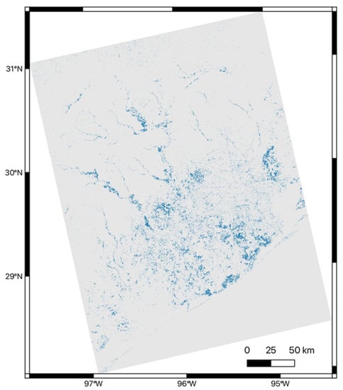
Figure 7.
Results from thresholding analysis of SAR GRD data, 29 August 2017, where flood waters are detected using the thresholding method described in Thresholding. Water is shown in blue and pixel spacing is 10 m, and permanent water bodies removed using the GWM.
Figure 8 shows the results from applying DeepLavv3+ ML analysis to the SAR GRD data, 29 August 2017, shown in Figure 6a. We also applied the ML analysis, DeepLabv3+, separately, to the RGB data from Figure 5b. The results are shown in Figure 9. The DeepLavb3+ analysis of the SAR GRD data, Figure 8, identifies more, smaller scale features in the data, while the DeepLavb3+ analysis of the false color RGB data identifies the most water pixels, particularly in the southern half of the image closest to the coast.
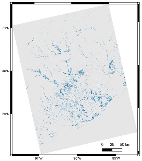
Figure 8.
Results from application of DeepLabv3+ to the SAR GRD data, 29 August 2017, shown in Figure 6a. Water pixels are shown in blue, pixel spacing is 10 m, permanent water bodies removed using the GWM.
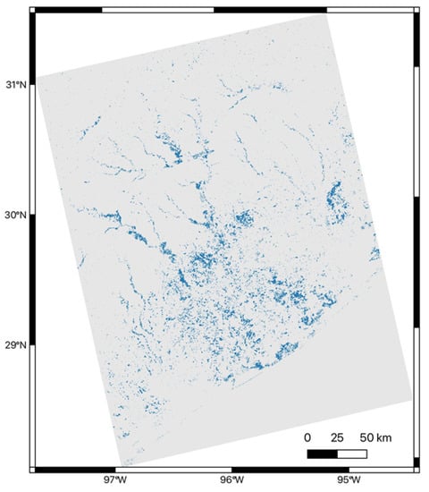
Figure 9.
Results from the DeepLabv3+ ML analysis applied to the false RGB data of Figure 5b. Water pixels are shown in blue, pixel spacing is 10 m, permanent water bodies removed using the GWM.
Figure 10 presents enlargements of the results from Figure 7, Figure 8 and Figure 9 that approximately correspond to the region overflown by NOAA, as shown in Figure 2. For comparison, we also provide enlargements for the DFO and NDWI results for the same region. Note that we again have removed the GWM from the results of Figure 10c–e. The same pattern emerges as observed in the larger images. The higher resolution analyses (10 m pixel spacing), whether the NDWI from the Sentinel-2 optical or the various Sentinel-1 SAR methods, all provide more detail than the DFO MODIS data at 250 m pixel spacing. Again, the thresholding analysis provides more detail than the NDWI analysis, based on images acquired closer in time to the hurricane landfall, while the water pixels in DeepLabv3+ ML analysis are denser, particularly closer to the coast.

Figure 10.
(a) Water pixels identified by MODIS data, courtesy of the DFO [41] 250 m pixel spacing; (b) water pixels identified from NDWI analysis of Sentinel-2 data, 10 m pixel spacing; (c) water pixels identified by the DeepLabv3+ analysis of SAR GRD data, 29 August 2017, 10 m pixel spacing; (d) water pixels identified from thresholding analysis of the same SAR GRD data, 10 m pixel spacing; and (e) water pixels identified by the ML analysis of the RGB classification of the SAR GRD data, 10 m pixel spacing. The GWM is removed from all results except the NDWI (b). Water pixels are shown in blue in all subfigures.
While the enlargements of Figure 10 provide additional detail on the differences in extent and coverage between these analyses, they are obtained over significantly different time intervals and spatial scales. To evaluate the effectiveness of each method at identifying actual water pixels, we compare the different results for three subregions of the NOAA optical images, as defined in Figure 2. The NOAA data were acquired between 27 August and 3 September 2017, covering this entire time period, and at a higher resolution than the NDWI or SAR analyses, with a GSD between 35 and 50 cm. Again, for comparison, we provide the original NOAA optical data, the DFO MODIS data, and the NDWI analysis from Sentinel-2, as described above. Note that we do not remove the GWM from our analysis, as the optical data contain both permanent and temporary water, although permanent water is masked out of the DFO MODIS data.
Figure 11 shows a comparison between subregion 1 of Figure 2 for the original optical data (Figure 11a), the DFO MODIS data (Figure 11b), Sentinel-2 NDWI analysis (Figure 11c), the DeepLabv3+ ML analysis of the SAR GRD data, 29 August 2017 (Figure 11d), the thresholding analysis of the SAR GRD data, 29 August 2017 (Figure 11e), and the DeepLabv3+ ML analysis of the RGB classification data (Figure 11f). Note that all the results identify the flood waters, with the DFO and NDWI effectively the same, with different resolutions, while the SAR analyses, at higher resolutions, present only minor differences.
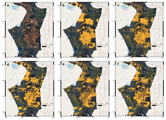
Figure 11.
(a) NOAA Remote Sensing Division airborne digital optical imagery of the Houston area acquired between 27 August and 3 September 2017, subregion 1, as shown in Figure 2; (b) water pixels identified by DFO MODIS data, 250 m pixel spacing, courtesy of the DFO [41]; (c) water pixels identified from NDWI analysis of Sentinel-2 data, 10 m pixel spacing; (d) water pixels identified by the DeepLabv3+ analysis of SAR GRD data, 29 August 2017, 10 pixel spacing; (e) water pixels identified from thresholding analysis of the same SAR GRD data, 10 m pixel spacing; and (f) water pixels identified by the classification analysis of the SAR GRD data, 10 m pixel spacing. The GWM is not removed from the analyses of (b) through (f). Water pixels are shown in orange.
Figure 12 shows a comparison between subregion 2 of Figure 2 for the original optical data (Figure 12a), the DFO MODIS data (Figure 12b), Sentinel-2 NDWI analysis (Figure 12c), the DeepLabv3+ ML analysis of the SAR GRD data, 29 August 2017 (Figure 12d), the thresholding analysis of the SAR GRD data, 29 August 2017 (Figure 12e), and the DeepLabv3+ ML analysis of the RGB classification data (Figure 12f). Here the results for the DFO and NDWI again fail to identify the bulk of the floodwaters. The SAR analyses succeed in identifying the permanent and flooded water pixels, capturing the sinuosity of the local channel, although the DeepLabv3+ analysis of the SAR GRD data (Figure 12d) identifies fewer of the flood pixels and the false color RGB analysis even fewer. The Sentinel-2 images employed in this analysis were collected on 30 August and 1 September 2017, while the SAR data were collected on 29 August 2017, and Hurricane Harvey made landfall on 26 August 2017. As noted above, flood inundation extent certainly varied over the time period, and it is likely that the flood waters had receded some between the time of the Sentinel-1 and Sentinel-2 acquisitions, accounting for the inability of the NDWI analysis to properly classify water pixels in Figure 12c.
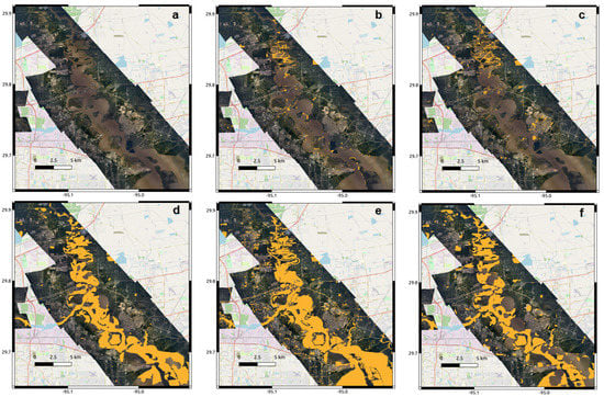
Figure 12.
(a) NOAA Remote Sensing Division airborne digital optical imagery of the Houston area acquired between 27 August and 3 September 2017, subregion 2, as shown in Figure 2; (b) water pixels identified by MODIS data, 250 m pixel spacing, courtesy of the DFO [41]; (c) water pixels identified from NDWI analysis of Sentinel-2 data, 10 m pixel spacing; (d) water pixels identified by the DeepLabv3+ analysis of SAR GRD data, 29 August 2017, 10 m pixel spacing; (e) water pixels identified from thresholding analysis of the same SAR GRD data, 10 m pixel spacing; and (f) water pixels identified by the classification analysis of the SAR GRD data, 10 m pixel spacing. The GWM is not removed from the analyses of (b) through (f). Water pixels are shown in orange.
Figure 13 shows a comparison between subregion 3 of Figure 2 for the original optical data (Figure 13a), the DFO MODIS data (Figure 13b), Sentinel-2 NDWI analysis (Figure 13c), the DeepLabv3+ ML analysis of the SAR GRD data, 29 August 2017 (Figure 13d), the thresholding analysis of the SAR GRD data, 29 August 2017 (Figure 13e), and the DeepLabv3+ ML analysis of the RGB classification data (Figure 13f). Here, flood waters are much narrower and the DFO analysis can only identify 250 m pixels at what appears to be random locations. The NDWI analysis (10 m pixel spacing) identifies permanent water pixels in the channels and adjacent ponding. The thresholding SAR analysis (Figure 13e) identifies the permanent water pixels and small ponding areas but also misidentifies large roadways as flooded pixels, probably because they are wet, with similar backscatter properties to a flat water surface (Figure 13e). The DeepLabv3+, however, captures the larger flood areas (Figure 13d), although the ML analysis of the RGB classification data shows large false positive areas associated with sinusoidal shapes (Figure 13f).
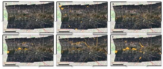
Figure 13.
(a) NOAA Remote Sensing Division airborne digital optical imagery of the Houston area acquired between 27 August and 3 September 2017, subregion 3, as shown in Figure 2; (b) water pixels identified by MODIS data, 250 m pixel spacing, courtesy of the DFO [41]; (c) water pixels identified from NDWI analysis of Sentinel-2 data, 10 m pixel spacing; (d) water pixels identified by the DeepLabv3+ analysis of SAR GRD data, 29 August 2017, 10 m pixel spacing; (e) water pixels identified from thresholding analysis of the same SAR GRD data, 10 m pixel spacing; and (f) water pixels identified by the classification analysis of the SAR GRD data, 10 m pixel spacing. The GWM is not removed from the analyses of (b) through (f). Water pixels are shown in orange.
4. Discussion
Characterization of flood inundation poses a unique problem at the intersection of remote sensing and hazard estimation, as evidenced by this study. Because Landsat and Sentinel-2 images are only usable under cloud-free conditions, their data are not always viable. Sentinel-1 data are only available every 12 days, which does not always match with maximum inundation, making it difficult to incorporate into real-time hazard analysis. While large amounts of remote sensing data exist for Hurricane Harvey, the temporal coverage does not overlap. In addition, variable spatial scales add to the difficulty of comparing the various analyses. However, the collection of high-resolution optical data by the NOAA Remote Sensing Division presents a unique opportunity to assess the qualitative advantages of the analyses shown here.
The high-resolution SAR GRD thresholding analysis, at 10 m pixel spacing, identifies water surfaces, both narrow and broader flooded areas, with good reliability. In all three comparisons with the NOAA data (Figure 11e, Figure 12e and Figure 13e), this method is successful in identifying not only larger flood areas, but small, narrow ponding areas. However, it also identifies a number of false positives in Figure 13e, associated with wet road surfaces.
The DeepLabv3+ ML analysis of the SAR GRD images, again at 10 m pixel spacing, is also very effective at identifying inundated water surfaces in all three test cases (Figure 11d, Figure 12d and Figure 13d). While the thresholding analysis may do better at identifying small features, the ML analysis has fewer false positives, and better characterizes the shape and nature of the significant flood areas.
The DeepLabv3+ ML analysis of the false color RGB data, also at 10 m pixel spacing, does well in large, flooded areas (Figure 11f), but does not do as well as the other methods in areas with more sinuous or smaller flood regions (Figure 12f and Figure 13f). This is despite the fact that the analysis is performed on three times the data as the ML analysis of the SAR GRD data—VH, VV, and VH/VV. Additional studies should investigate comparisons of analysis of the three channels separately, to better understand the factors affecting their results and ability to appropriately characterize flooding.
A visual comparison of all three high-resolution analyses, at 10 m pixel spacing, suggests that they all do a better job of characterizing flood inundation than either the DFO MODIS data (250 m pixel scaling) and NDWI (10 m pixel scaling) for smaller scale flood features and that the SAR data have a unique ability to better characterize flood inundation, a function of both its ability to identify water surfaces and to see through cloud coverage associated with large storms. However, a direct comparison is difficult because none of the images are acquired on the same dates.
To better evaluate the performance of the three classification methods—DeepLabv3+, thresholding, and DeepLabv3+ ML analysis of the false color RGB data—we performed a predictive analysis using confusion matrices (Figure 14). We compared each method to a subset of the data for the Sentinel-2 NDWI analysis of Figure 4. The test region ranges from −96.25° to −95.20° E longitude and 29.25° to 30.25° N latitude, which encompasses most of the area overflown by NOAA (Figure 2) without including the Gulf of Mexico to the south. This is not a perfect comparison because the Sentinel-2 images employed in that analysis were collected on 30 August and 1 September 2017, while the SAR data were collected on 29 August 2017, and Hurricane Harvey made landfall on 26 August 2017. As noted above, flood inundation extent certainly varied over the time period, and it is likely that the flood waters had receded some between the time of the Sentinel-2 and SAR acquisitions. However, the Sentinel-2 NDWI is produced at the same 10 m pixel spacing as the SAR GRD results, providing for a direct comparison without rescaling.
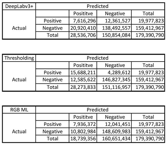
Figure 14.
Confusion matrices for DeepLabv3+ analysis compared with Sentinel-2 NDWI analysis; thresholding analysis compared with Sentinel-2 NDWI analysis; and false color RGB ML analysis compared with Sentinel-2 NDWI analysis. In each, the top left box shows true positives (tp), the top right shows false positives (fp), bottom left shows false negatives (fn) and bottom right shows true negatives (tn) for each comparison.
Table 1 shows the results of computing the precision, p [p = (tp)/(tp + fp)], recall, r [r = (tp)/(tp + fn)], and F1-score [f1 = 2∙p∙r)/(p + r)]. The precision of the classification model identifies how many, out of all instances that were predicted to be water, actually were water. The recall identifies how many instances of water were predicted correctly. Finally, the F1-score compares multiple classes by combining the precision and the recall into a single metric by taking their harmonic mean. The F1-score can be used to compare the performance of two or more classifiers. The higher the F1-score, the better the classifier.

Table 1.
Precision, p, recall, r, and F1-score for results from the DeepLabv3+, thresholding and false RGB ML analysis.
The results from Table 1 suggest that the thresholding technique provides a better result than either the DeepLabv3+ analysis of the SAR GRD data or the false color RGB data. This may be because of the lower number of false positives associated with the thresholding method or, inversely, the larger number associated with the ML analysis. The higher number of false positives associated with the ML analysis is likely because the training data largely rely on the shape of coherent pixels. Additional training data over a wider variety of regions and sizes should be investigated in the future.
5. Conclusions
Disaster resilience is a widely used concept that focuses on increasing the ability of a community or a set of infrastructure to recover after disasters by responding, recovering, and adapting with minimal loss within a short period of time [58,59,60,61,62]. Resilience is impacted by societal, political, and cultural variables, but it also is advanced through technological innovations [63,64]. Being a multi-dimensional concept, its operationalization requires achieving four properties robustness, resourcefulness, rapidity, and redundancy [59,65]. In particular, improved risk assessment and risk communication are critical factors in increasing resilience through better preparedness, mitigation, and response [66,67]. For example, today technological advances enable the rapid dissemination of disaster information via mobile communication and social media [8,9].
Large flood events, combined with coastal urbanization, present a unique challenge to coastal cities and megacities, contribute to significant economic losses, and damage buildings and infrastructure. Detailed and accurate characterization of impending and ongoing flood hazards is critical to aid effective preparation and subsequent response to reduce the impact of large flood events. However, no communication platform currently exists that delivers rapid flood assessment and impact analysis worldwide. DisasterAWARE®, a platform operated by the Pacific Disaster Centre (PDC) that provides warning and situational awareness information through mobile apps and web-based platforms to millions of users worldwide, is developing a component that will provide flood forecasting and impact assessment [68].
DisasterAWARE® implements an integrated modelling approach that consists of (i) a Model of Models (MoM) to integrate hydrological models for flood forecasting and risk assessment, (ii) flood extent and depth modelling using SAR imagery at a granular level for high severity floods identified in (i), and (iii) infrastructure impact assessment using high-resolution optical imagery and geospatial data sets. Specifically, the MoM generates flood extent output at the watershed level at regular time intervals (currently 6 h) during a flood event using outputs from established hydrologic models (e.g., GloFAS (Global Flood Awareness System) and GFMS (Global Flood Monitoring System) [68,69]. The MoM output then identifies SAR imagery for high flood severity locations so that flood extent could be generated at high resolution, such as the 10 m pixel spacing presented here, along with optical imagery and geospatial datasets to assess impacts. Integration of the SAR flood mapping data from the research presented here will allow for the generation of alerts about imminent flood hazard, flooding locations and severity, and flood impacts to infrastructure. For Sentinel-1A data, these will be limited by the repeat time of the acquisitions, currently at 12 days with the malfunction of Sentinel-1B. However, integration of additional data sets, such as C-band SAR from the Radarsat Constellation Mission (RCM) or the upcoming L-band NISAR satellite, could lower the repeat times to 4-to-6 days, The addition of commercial data sets from small satellite constellations such as ICEYE could provide updates with repeat times of less than one day.
Here, we present a comparison of several methods for identifying flood inundation using a combination of SAR remote sensing data and ML methods that can be incorporated into operational flood forecasting systems such as DisasterAWARE® and provide a comparison of their effectiveness relative to a NDWI analysis of Sentinel-2 data. These employ SAR data to characterize flooding at unprecedented resolutions of 10 m pixel spacing, for Hurricane Harvey, which struck Houston, TX, on 26 August 2017. We present two applications applied, for the first time, to Sentinel-1 GRD data, an amplitude thresholding technique and a machine learning technique, DeepLabv3+. We also apply DeepLabv3+ to a false color RGB characterization of dual polarization SAR data. We compare these 10 m pixel spacing results with high-resolution aerial optical images over this time period, acquired by NOAA Remote Sensing Division, DFO MODIS data [15], and an NDWI estimation using Sentinel-2 images, also at 10 m pixel spacing.
Although the thresholding method is most effective at identifying small scale flood features in terms of precision, recall, and F1-score, results show more false positives, associated with flat, wet surfaces such as roadways (Figure 13e). The DeepLabv3+ ML analysis also is very effective, although it does produce fewer true positives, as well as more false negatives (Figure 14). Future studies should investigate potential improvements using expanded training data sets. Both methods (applied to the SAR GRD data) are more effective at identifying both large- and small-scale flood inundation over this time period than the DFO data. Although it is difficult to quantify, given that the acquisition dates are different for all data sources, visual comparison with NOAA optical imagery suggests that they can successfully identify both small and large ponding areas, as well as permanent water bodies (Figure 13).
Future work should investigate improvements in these SAR methods, including investigations into both longer time series from historical archives, such as Radarsat1/2, ALOS, and ERS/ENVISAT, incorporating DEM data (height and slope) into both the thresholding and ML analyses, quantitative comparison, and improved quantity and quality of training data for the ML method. Detailed studies of the false color RGB data may provide insights into their ability to characterize water and other land cover types. In addition, while the Sentinel-1/2 constellation and the recent Landsat-8 and upcoming Landsat-9 missions have significantly improved the temporal and spatial mapping of large flood extents, additional satellite data can be used, both pre- and post-flood, to improve that temporal resolution in the future. Accuracy and sensitivity testing of other SAR frequency bands will provide important information on the potential for incorporating data from the upcoming NISAR (NASA-ISRO SAR) mission, which will have both L- and S-band SAR sensors, into operational flood forecasting.
Current SAR flood products are produced at 30 m resolution [70]. In this work, we have demonstrated the efficacy of high-resolution SAR analyses, at 10 m pixel spacing, for improved characterization of flood features at all scales and can be incorporated into operational flood forecasting tools, improving response and resilience to large flood events.
Author Contributions
Conceptualization, K.F.T., L.H., C.S. and C.W.; methodology, K.F.T., C.W., L.H. and C.S.; software, C.W., L.H. and C.S.; validation, K.F.T., L.H. and C.S.; formal analysis, L.H., C.S. and C.W.; investigation, L.H., C.S. and C.W.; resources, M.T.G. and K.F.T.; data curation, K.F.T., L.H. and C.S.; writing—original draft preparation, K.F.T., L.H. and C.S.; writing—review and editing, K.F.T., L.H., C.S. and M.T.G.; visualization, L.H. and C.S.; supervision, K.F.T. and M.T.G.; project administration, K.F.T. and M.T.G.; funding acquisition, K.F.T. and M.T.G. All authors have read and agreed to the published version of the manuscript.
Funding
This research was carried out under NASA Grant 80NM0018D0004, Advancing Access to Global Flood Modeling and Alerting using the PDC DisasterAWARE Platform and Remote Sensing Technologies.
Data Availability Statement
DFO data are available for scholarly research on request from the Dartmouth Flood Observatory (G. Robert Brakenridge, DFO Flood Observatory, University of Colorado, February 2021. Global Active Archive of Large Flood Events, 1985–Present, https://floodobservatory.colorado.edu/; accessed on 22 February 2021). NOAA optical imagery is available from https://storms.ngs.noaa.gov/storms/harvey/download/metadata.html (accessed on 1 February 2021). The Global Surface Water map is available at https://global-surface-water.appspot.com/download (accessed on 17 May 2021). Copernicus Sentinel-1 GRD data [2015–2021] can be retrieved from ASF DAAC, processed by ESA (accessed on 9 June 2021). Sentinel-2 data used in this study is available from Copernicus Sentinel-2 Level-1C data (2015–2021). Retrieved from Google Earth Engine [https://developers.google.com/earth-engine/datasets/catalog/sentinel (accessed on 5 October 2021)], processed by ESA (see Table 1).
Conflicts of Interest
The authors declare no conflict of interest. The funders had no role in the design of the study; in the collection, analyses, or interpretation of data; in the writing of the manuscript, or in the decision to publish the results.
References
- Centre for Research on the Epidemiology of Disasters—CRED. EM-DAT: The International Disaster Database, Université catholique de Louvain: Brussels, Belgium. Available online: https://www.emdat.be/ (accessed on 2 July 2020).
- Hallegatte, S.; Green, C.; Nicholls, R.J.; Corfee-Morlot, J. Future flood losses in major coastal cities. Nat. Clim. Chang. 2013, 3, 802–806. [Google Scholar] [CrossRef]
- Science Daily. Two Billion Vulnerable to Floods by 2050; Number Expected to Double or More in Two Generations; United Nations University: Tokyo, Japan, 2004; Available online: sciencedaily.com/releases/2004/06/040614081820.htm (accessed on 6 March 2022).
- Edenhofer, O.; Pichs-Madruga, R.; Sokona, Y.; Farahani, E.; Kadner, S.; Seyboth, K.; Adler, A.; Baum, I.; Brunner, S.; Eickemeier, P.; et al. Climate Change 2014: Mitigation of Climate Change. In Contribution of Working Group III to the Fifth Assessment Report of the Intergovernmental Panel on Climate Change; Cambridge University Press: Cambridge, UK, 2014. [Google Scholar]
- Reynolds, B.; Seeger, M.W. Crisis and emergency risk communication as an integrative model. J. Health Commun. 2005, 10, 43–55. [Google Scholar] [CrossRef] [PubMed]
- Gladwin, H.; Lazo, J.K.; Morrow, B.H.; Peacock, W.G.; Willoughby, H.E. Social science research needs for the hurricane forecast and warning system. Nat. Hazards Rev. 2007, 8, 87–95. [Google Scholar] [CrossRef][Green Version]
- Krimsky, S. Risk communication in the internet age: The rise of disorganized skepticism. Environ. Hazards 2007, 7, 157–164. [Google Scholar] [CrossRef]
- Palen, L.; Vieweg, S.; Liu, S.B.; Hughes, A.L. Crisis in a networked world features of computer-mediated communication in the April 16, 2007, Virginia Tech event. Soc. Sci. Comp. Rev. 2009, 27, 1–14. [Google Scholar]
- Federal Emergency Management Agency. Integrated Alert and Warning System (IPAWS). 2012. Available online: http://www.fema.gov/emergency/ipaws/index.shtm (accessed on 1 June 2020).
- Islam, A.S.; Bala, S.K.; Haque, M. Flood inundation map of Bangladesh using MODIS time-series images. J. Flood Risk Manag. 2010, 3, 210–222. [Google Scholar] [CrossRef]
- Ahmed, M.R.; Rahaman, K.R.; Kok, A.; Hassan, Q.K. Remote Sensing-Based Quantification of the Impact of Flash Flooding on the Rice Production: A Case Study over Northeastern Bangladesh. Sensors 2017, 17, 2347. [Google Scholar] [CrossRef]
- Rahman, M.S.; Di, L.; Shrestha, R.; Eugene, G.Y.; Lin, L.; Zhang, C.; Hu, L.; Tang, J.; Yang, Z. Agriculture flood mapping with Soil Moisture Active Passive (SMAP) data: A case of 2016 Louisiana flood. In Proceedings of the 2017 6th International Conference on Agro-Geoinformatics, Fairfax, VA, USA, 7–10 August 2017. [Google Scholar]
- Turlej, K.; Bartold, M.; Lewiński, S. Analysis of extent and effects caused by the flood wave in May and June 2010 in the Vistula and Odra River Valleys. Geoinf. Issues 2010, 2, 49–57. [Google Scholar]
- De Roo, A.; Van Der Knij, J.; Horritt, M.; Schmuck, G.; De Jong, S. Assessing flood damages of the 1997 Oder flood and the 1995 Meuse flood. In Proceedings of the Second International ITC Symposium on Operationalization of Remote Sensing, Enschede, The Netherlands, 16–20 August 1999. [Google Scholar]
- Tholey, N.; Clandillon, S.; De Fraipont, P. The contribution of spaceborne SAR and optical data in monitoring flood events: Examples in northern and southern France. Hydrol. Process. 2015, 11, 1409–1413. [Google Scholar] [CrossRef]
- Hoque, R.; Nakayama, D.; Matsuyama, H.; Matsumoto, J. Flood monitoring, mapping and assessing capabilities using RADARSAT remote sensing, GIS and ground data for Bangladesh. Nat. Hazards 2011, 57, 525–548. [Google Scholar] [CrossRef]
- Henry, J.B.; Chastanet, P.; Fellah, K.; Desnos, Y.L. Envisat multi-polarized ASAR data for flood mapping. Int. J. Remote Sens. 2006, 27, 1921–1929. [Google Scholar] [CrossRef]
- Kuenzer, C.; Guo, H.; Huth, J.; Leinenkugel, P.; Li, X.; Dech, S. Flood Mapping and Flood Dynamics of the Mekong Delta: ENVISAT-ASAR-WSM Based Time Series Analyses. Remote Sens. 2013, 5, 687–715. [Google Scholar] [CrossRef]
- Ohki, M.; Watanabe, M.; Natsuaki, R.; Motohka, T.; Nagai, H.; Tadono, T.; Suzuki, S.; Ishii, K.; Itoh, T.; Yamanokuchi, T. Flood Area Detection Using ALOS-2 PALSAR-2 Data for the 2015Heavy Rainfall Disaster in the Kanto and Tohoku Area, Japan. J. Remote Sens. Soc. Jpn. 2016, 36, 348–359. [Google Scholar]
- Voormansik, K.; Praks, J.; Antropov, O.; Jagomagi, J.; Zalite, K. Flood mapping with TerraSAR-X in forested regions in Estonia. IEEE J. Sel. Top. Appl. Earth Obs. Remote Sens. 2014, 7, 562–577. [Google Scholar] [CrossRef]
- Iervolino, P.; Guida, R.; Iodice, A.; Riccio, D. Flooding Water Depth Estimation with High-Resolution SAR. IEEE Trans. Geosci. Remote Sens. 2015, 53, 2295–2307. [Google Scholar] [CrossRef]
- Cian, F.; Marconcini, M.; Ceccato, P.; Giupponi, C. Flood depth estimation by means of high-resolution SAR images and lidar data. Nat. Hazards Earth Syst. Sci. 2018, 18, 3063–3084. [Google Scholar] [CrossRef]
- Elkhrachy, I. Flash flood water depth estimation using SAR images, digital elevation models, and machine learning algorithms. Remote Sens. 2022, 14, 440. [Google Scholar] [CrossRef]
- Richards, J.A.; Woodgate, P.W.; Skidmore, A.K. An explanation of enhanced radar backscattering from flooded forests. Int. J. Remote Sens. 1987, 8, 1093–1100. [Google Scholar] [CrossRef]
- Hess, L.L.; Melack, J.M.; Simonett, D.S.; Sieber, A.J. Radar detection of flooding beneath the forest canopy: A review. Int. J. Remote Sens. 1990, 11, 1313–1325. [Google Scholar] [CrossRef]
- Townsend, P. Relationships between forest structure and the detection of flood inundation in forested wetlands using C-band SAR. Int. J. Remote Sens. 2002, 23, 443–460. [Google Scholar] [CrossRef]
- Dabrowska-Zielinska, K.; Budzynska, M.; Tomaszewska, M.; Bartold, M.; Gatkowska, M.; Malek, I.; Turlej, K.; Napiorkowska, M. Monitoring wetlands ecosystems using ALOS PALSAR (L-Band, HV) supplemented by optical data: A case study of Biebrza Wetlands in Northeast Poland. Remote Sens. 2014, 6, 1605–1633. [Google Scholar] [CrossRef]
- Oberstadler, R.; Hönsch, H.; Huth, D. Assessment of the mapping capabilities of ERS-1 SAR data for flood mapping: A case study in Germany. Hydrol. Process. 1997, 11, 1415–1425. [Google Scholar] [CrossRef]
- Dewan, A.M.; Islam, M.M.; Kumamoto, T.; Nishigaki, M. Evaluating flood hazard for land-use plannin in Greater Dhaka of Bangladesh using remote sensing and GIS techniques. Water Resour. Manag. 2007, 21, 1601–1612. [Google Scholar] [CrossRef]
- Townsend, P.A. Estimating forest structure in wetlands using multitemporal SAR. Remote Sens. Environ. 2002, 79, 288–304. [Google Scholar] [CrossRef]
- Schumann, G.; Henry, J.; Homann, L.; Pfister, L.; Pappenberger, F.; Matgen, P. Demonstrating the high potential of remote sensing in hydraulic modelling and flood risk management. In Proceedings of the Annual Conference of the Remote Sensing and Photogrammetry Society with the NERC Earth Observation Conference, Portsmouth, UK, 6–9 September 2005. [Google Scholar]
- Uddin, K.; Abdul Matin, M.; Meyer, F.J. Operational flood mapping using multi-temporal Sentinel-1 SAR images: A case study from Bangladesh. Remote Sens. 2019, 11, 1581. [Google Scholar] [CrossRef]
- Bates, P.; Horritt, M.; Smith, C.; Mason, D. Integrating remote sensing observations of flood hydrology and hydraulic modelling. Hydrol. Process. 1997, 11, 1777–1795. [Google Scholar] [CrossRef]
- Matgen, P.; Schumann, G.; Henry, J.B.; Homann, L.; Pfister, L. Integration of SAR-derived river inundation areas, high-precision topographic data and a river flow model toward near real-time flood management. Int. J. Appl. Earth Obs. Geoinf. 2007, 9, 247–263. [Google Scholar] [CrossRef]
- Delmeire, S. Use of ERS-1 data for the extraction of flooded areas. Hydrol. Process 1997, 11, 1393–1396. [Google Scholar] [CrossRef]
- Bazi, Y.; Bruzzone, L.; Melgani, F. An unsupervised approach based on the generalized Gaussian model to automatic change detection in multitemporal SAR images. IEEE Trans. Geosci. Remote Sens. 2005, 43, 874–887. [Google Scholar] [CrossRef]
- Refice, A.; D’Addabbo, A.; Capolongo, D. Flood Monitoring through Remote Sensing; Springer Remote Sensing/Photogrammetry Series; Springer: Cham, Switzerland, 2018; Available online: https://doi.org/10.1007/978-3-319-63959-8 (accessed on 22 January 2020).
- Cao, H.; Zhang, H.; Wang, C.; Zhang, F. Operational flood detection using Sentinel-1 SAR data over large areas. Water 2019, 11, 786. [Google Scholar] [CrossRef]
- ESA. SNAP—ESA Sentinel Application Platform, v8.0. Available online: https://step.esa.int (accessed on 9 June 2021).
- Frulla, L.A.; Milovich, J.A.; Karszenbaum, H.; Gagliardini, D.A. Radiometric corrections and calibration of SAR images. In IGARSS’98. Sensing and Managing the Environment. 1998 IEEE International Geoscience and Remote Sensing. Symposium Proceedings. (Cat. No. 98CH36174); IEEE: Piscataway, NJ, USA, 1998; Volume 2, pp. 1147–1149.a. [Google Scholar]
- Brakenridge, G.R.; DFO Flood Observatory. Global Active Archive of Large Flood Events, 1985-Present; University of Colorado: Boulder, CO, USA, 2021. [Google Scholar]
- Pekel, J.-F.; Cottam, A.; Gorelick, N.; Belward, A.S. High-resolution mapping of global surface water and its long-term changes. Nature 2016, 540, 418–422. [Google Scholar] [CrossRef] [PubMed]
- Gorelick, N.; Hancher, M.; Dixon, M.; Ilyushchenko, S.; Thau, D.; Moore, R. Google Earth Engine: Planetary-scale geospatial analysis for everyone. Remote Sens. Environ. 2017, 202, 18–27. [Google Scholar] [CrossRef]
- Ajadi, O.A.; Meyer, F.J.; Webley, P.W. Change detection in synthetic aperture radar images using a multiscale-driven approach. Remote Sens. 2016, 8, 482. [Google Scholar] [CrossRef]
- D’Addabbo, A.; Refice, A.; Pasquariello, G.; Lovergine, F.P.; Capolongo, D.; Manfreda, S. A Bayesian network for flood detection combining SAR imagery and ancillary data. IEEE Trans. Geosci. Remote Sens. 2016, 54, 3612–3625. [Google Scholar] [CrossRef]
- Gong, M.; Zhao, J.; Liu, J.; Miao, Q.; Jiao, L. Change detection in synthetic aperture radar images based on deep neural networks. IEEE Trans. Neural Netw. Learn. Syst. 2016, 27, 125–138. [Google Scholar] [CrossRef]
- Bayik, C.; Abdikan, S.; Ozbulak, G.; Alasag, T.; Aydemir, S.; Balik, S.F. Exploiting multi-temporal Sentinel-1 SAR data for flood extent mapping. Int. Arch. Photogr. Rem. Sens. Spatial Inf. Sci. 2018, XLII-3/W4, 109–113. [Google Scholar] [CrossRef]
- Li, Y.; Martinis, S.; Wieland, M. Urban flood mapping with an active self-learning convolutional neural network based on TerraSAR-X intensity and interferometric coherence. ISPRS J. Photogr. Rem. Sens. 2019, 152, 178–191. [Google Scholar] [CrossRef]
- McFeeters, S.K. The use of the Normalized Difference Water Index (NDWI) in the delineation of open water features. Int. J. Remote Sens. 1996, 17, 1425–1432. [Google Scholar] [CrossRef]
- Xu, H. Modification of normalised difference water index (NDWI) to enhance open water features in remotely sensed imagery. Int. J. Remote Sens. 2006, 27, 3025–3033. [Google Scholar] [CrossRef]
- Demirkaya, O.; Asyali, M.H. Determination of image bimodality thresholds for different intensity distributions. Signal Process. Image Commun. 2004, 19, 507–516. [Google Scholar] [CrossRef]
- Huang, L.; Liu, L.; Jiang, L.; Zhang, T. Automatic Mapping of Thermokarst Landforms from Remote Sensing Images Using Deep Learning: A Case Study in the Northeastern Tibetan Plateau. Remote Sens. 2018, 10, 2067. [Google Scholar] [CrossRef]
- Huang, L.; Lu, J.; Lin, Z.; Niu, F.; Liu, L. Using deep learning to map retrogressive thaw slumps in the Beiluhe region (Tibetan Plateau) from CubeSat images. Remote Sens. Environ. 2019, 237, 111534. [Google Scholar] [CrossRef]
- Chen, L.-C.; Papandreou, G.; Kokkinos, L.; Murphy, K.; Yuille, A.L. Semantic image segmentation with deep convolutional nets and fully connected CRFs. In Proceedings of the International Conference on Learning Representations (ICLR), San Diego, CA, USA, 7–9 May 2015. [Google Scholar]
- Zhang, E.; Liu, L.; Huang, L.; Ng, K.S. An automated, generalized, deep-learning-based method for delineating the calving fronts of Greenland glaciers from multi-sensor remote sensing imagery. Remote Sens. Environ. 2021, 254, 112265. [Google Scholar] [CrossRef]
- Chollet, F. Xception: Deep learning with depthwise separable convolutions. In Proceedings of the IEEE Conference on Computer Vision and Pattern Recognition (CVPR), Honolulu, HI, USA, 21–26 July 2017; pp. 1800–1807. [Google Scholar] [CrossRef]
- Russakovsky, O.; Deng, J.; Su, H.; Krause, J.; Satheesh, S.; Ma, S.; Huang, Z.; Karpathy, A.; Khosla, A.; Bernstein, M.; et al. Imagenet large scale visual recognition challenge. Int. J. Comput. Vis. 2015, 115, 211–252. [Google Scholar] [CrossRef]
- Holling, C.S. Resilience and stability of ecological systems. Annu. Rev. Ecol. Syst. 1973, 4, 1–23. [Google Scholar] [CrossRef]
- Bruneau, M.; Chang, S.E.; Eguchi, R.T.; Lee, G.C.; O’Rourke, T.D.; Reinhorn, A.M.; Winterfeldt, D.V. A framework to quantitatively assess and enhance the seismic resilience of communities. Earthq. Spectra 2003, 19, 733–752. [Google Scholar] [CrossRef]
- Klein, R.J.T.; Nicholls, R.J.; Thomalla, F. The resilience of coastal megacities to weather-related hazards. In Building Safer Cities: The Future of Disaster Risk; Kreimer, A., Arnold, M., Carlin, A., Eds.; The World Bank Disaster Management Facility: Washington, DC, USA, 2003. [Google Scholar]
- Paton, D.; Johnston, D. Disaster Resilience: An Integrated Approach; Charles C. Thomas: Springfield, IL, USA, 2006. [Google Scholar]
- Cutter, S.L.; Barnes, L.; Berry, M.; Burton, C.; Evans, E.; Tate, E.; Webb, J. A place-based model for understanding community resilience to natural disasters. Glob. Environ. Chang. 2008, 18, 598–606. [Google Scholar] [CrossRef]
- Mileti, D.S. Disasters by Design: A Reassessment of Natural Hazards in the United States; Joseph Henry Press: Washington, DC, USA, 1999. [Google Scholar]
- Rose, A. Defining and measuring economic resilience to disasters. Disaster Prev. Manag. 2004, 13, 307–314. [Google Scholar] [CrossRef]
- Renschler, C.; Frazier, A.; Arendt, L.; Cimellaro, G.; Reinhorn, A.; Bruneau, M. Framework for Defining and Measuring Resilience at the Community Scale: The PEOPLES Resilience Framework (MCEER-10-0006); University of Buffalo: Buffalo, NY, USA, 2010. [Google Scholar]
- UNDRR. Sendai Framework for Disaster Risk Reduction 2015–2030, United Nations. 2015. Available online: https://www.undrr.org/publication/sendai-framework-disaster-risk-reduction-2015-2030 (accessed on 15 March 2022).
- UN/ISDR (Inter-Agency Secretariat of the International Strategy for Disaster Reduction). Hyogo Framework for Action 2005–2015: Building the Resilience of Nations and Communities to Disasters (HFA); UNISDR: Kobe, Japan, 2005. [Google Scholar]
- Sharma, P.; Wang, J.; Zhang, M.; Woods, C.; Kar, B.; Bausch, D.; Chen, Z.; Tiampo, K.; Glasscoe, M.; Schumann, G.; et al. DisasterAWARE—A global alerting platform for flood events. Climate Change and Disaster Management, Technology and Resilience in a Troubled World, Geographic Information for Disaster Management (GI4DM), Sydney, Australia. ISPRS Ann. Photogramm. Remote Sens. Spat. Inf. Sci. 2020, VI-3/W1, 107–113. [Google Scholar] [CrossRef]
- Emerton, R.E.; Stephens, E.M.; Pappenberger, F.; Pagano, T.C.; Weerts, A.H.; Wood, A.W.; Cloke, H.L. Continental and global scale flood forecasting systems. WIREs Water 2016, 3, 391–418. [Google Scholar] [CrossRef]
- Meyer, F.J.; Meyer, T.; Osmanoglu, B.; Kennedy, J.H.; Kristenson, H.; Schultz, L.A.; Bell, J.R.; Molthan, A.; Abdul Matin, M. A cloud-based operational surface water extent mapping Service from Sentinel-1 SAR. In Proceedings of the American Geophysical Union Fall Meeting, New Orleans, LA, USA, 13–17 December 2021. [Google Scholar]
Publisher’s Note: MDPI stays neutral with regard to jurisdictional claims in published maps and institutional affiliations. |
© 2022 by the authors. Licensee MDPI, Basel, Switzerland. This article is an open access article distributed under the terms and conditions of the Creative Commons Attribution (CC BY) license (https://creativecommons.org/licenses/by/4.0/).