Article

Source Geometry and Causes of the 2019 Ms6.0 Changning Earthquake in Sichuan, China Based on InSAR

1
State Key Laboratory of Information Engineering in Surveying, Mapping, and Remote Sensing, Wuhan University, Wuhan 430079, China
2
School of Geosciences and Info-Physics, Central South University, Changsha 410083, China
3
Key Laboratory of Metallogenic Prediction of Nonferrous Metals and Geological Environment Monitoring, Central South University, Ministry of Education, Changsha 410083, China
*
Author to whom correspondence should be addressed.
Remote Sens. 2022, 14(9), 2082; https://doi.org/10.3390/rs14092082
Submission received: 29 March 2022 / Revised: 24 April 2022 / Accepted: 25 April 2022 / Published: 26 April 2022

Abstract

:
On 17 June 2019, an Ms6.0 earthquake occurred in Changning, Sichuan, China (Changning event), which was the largest earthquake on record within 50 km of the area. It attracted great attention as the area has the largest shale gas production in China as well as significant mineral salt production. Using the Interferometric Synthetic Aperture Radar (InSAR), we extract the coseismic deformation of the Changning event and two earlier Ms > 5.0 earthquakes which occurred in the same region (16 December 2018 Ms5.7 and 3 January 2019 Ms5.3) from the Sentinel-1 and ALOS2 data. We use nonlinear and linear methods to invert the fault models of the three earthquakes based on the deformation fields. The final model shows that the Changning event was caused by a fault with left-lateral strike and thrust slip. The strike is 124.3° with a dip angle of 43.4°. The seismic moment obtained by inversion is 5.28 × 10¹⁷ Nm, corresponding to Mw 5.78. Based on the fault models, we analyze the cause of the Changning earthquake considering the local tectonic setting, Coulomb stress change, mining, and fluid injection. We consider that the event may be related to salt mining. The two earlier Ms > 5.0 earthquakes may also play an important role in advancing the Changning earthquake.

Graphical Abstract

1. Introduction

On the night of 17 June 2019 (local time, UTC + 8), an Ms6.0 earthquake struck Changning county of Sichuan province (hereafter referred to as the Changning event), a region with an important shale gas reservoir. In addition, 609 aftershocks, including three Ms > 5 events, occurred in the following five days (Figure 1) [1]. On 4 July 2019, another M > 5 aftershock occurred on the northwest side of the mainshock. The Changning event is the largest earthquake instrumentally recorded in the region within 50 km, according to the report of the China Earthquake Network Center (CENC, https://www.cenc.ac.cn/, accessed on: 20 April 2022). The earthquake caused obvious local fractures [2]. Before the Changning event, salt mining resulted in abnormal seismic activities in this area, and the frequency of small earthquakes increased significantly (including four M > 4 earthquakes) compared with no salt mining [3,4]. An Ms5.7 (hereafter referred to as P1) and an Ms5.3 (hereafter referred to as P2) earthquake occurred on 16 December 2018 and 3 January 2019, respectively, south of the Changning event. Some studies suggested that the two earthquakes may relate to the hydraulic fracturing of the local shale gas production [5].
In recent years, earthquakes caused by human activities, including hydraulic fracturing, salt mining, or wastewater injection, have attracted increasing attention [5,8,9]. The epicenter of the Changning earthquake is in the fold transition zone, which accommodates a large reservoir of shale gas and salt mines [3,7,10]. There are some shale gas wells and salt mining wells around the earthquake area. The water injection or hydraulic fracturing may have some effects on the regional geological structure [5,6,8,11,12]. However, how the Changning event occurred remains a topic of debate [1,6,10,13]. In this study, the earthquakes caused by human activities are referred to as induced earthquakes, and those caused by other earthquakes or natural activities are called triggered earthquakes [6,14].
In this study, we analyze the earthquake deformation, fault structure, and seismogenic mechanism using the Interferometric Synthetic Aperture Radar (InSAR) data. We obtain and analyze the coseismic deformation fields of the Changning, P1, and P2 events, and derive their source parameters and slip distribution models using a non-linear search algorithm and linear inversion. Based on the fault models, we analyze the causes of the Changning earthquake by three points. (1) We analyze the geological structure of the earthquake area. (2) We use the Coulomb stress change models to investigate the effect of events P1 and P2 on the causative fault of the Changning event. (3) Considering the relationship between water loss and the expected maximum magnitude, we analyze the possible relationship between the Changning earthquake, salt mine exploitation, and hydraulic fracturing. Finally, we analyze the distribution pattern of the aftershocks of the Changning event to find information about the underground fault structure and the relationship between the mainshock and aftershocks.

2. Tectonic Setting

The Changning event occurred on the border of the southern Sichuan Basin, in the transition area from the gentle fold belt in South Sichuan to the Daliangshan–Daloushan fault–fold structural belt. This region has multi-stage structural deformation superposing over each other in different directions [10]. Tectonic movements result in many crisscrossing mountains and gullies in this area. The elevation of the region is between 300 and 1400 m, and the local height difference is larger than 400 m. The epicenter of the Changning event is located on the Changning–Shuanghe anticline. The compound anticline system consists of the Changning anticline, Shuanghechang anticline, Baixiangyan–Shizitan anticline, Tenglong anticline, etc. The Changning–Shuanghe anticline is wider in the southeast and narrower in the northwest. The axis trace of the anticline is from NW to SE. GPS data show a crustal movement from NW to SE in this area [15]. The core of the anticline is exposed to Cambrian, and the periphery successively includes Ordovician, Silurian, Permian, Triassic, and Jurassic [10,16]. The northern section of the earthquake area is adjacent to the Xiangling syncline, and the southern is adjacent to the Luochang syncline, the Yuhe anticline, and the Jianwu syncline. There are several fragmentary faults in the earthquake area, such as the Dafenba fault, the Dadiwan fault, the Wafangtou fault, and the Gongxian fault (Figure 1) [1].

3. Data and Methods

3.1. D-InSAR Coseismic Deformation Processing

InSAR is an important technology for studying the static coseismic deformation, fault parameters, earthquake triggering relationship [17,18,19,20], and secondary disasters [21,22,23].
We use Differential-InSAR (D-InSAR) to generate the coseismic deformation fields of the Changning, P1, and P2 events and two aftershocks (Table 1). We obtain the images acquired by Sentinel-1 (IW mode) and ALOS2 satellites (Strip map mode) from ascending and descending orbits before and after these events (see Table 1 for details). As the descending images of P1 and Changning events have very poor quality, they are not used in this study.
We use the GAMMA software for InSAR processing [24]. We apply the multi-look operation of 10:2 and 6:16 (Range: Azimuth) to the original Sentinel-1 and ALOS2 images, respectively. With coregistration and interference processing, we obtain interferograms. Then, the Shuttle Radar Topography Mission DEM (SRTM) (resolution 90 m) is used to simulate the topographic phase [25]. We remove the topographic effect and flat effect based on the simulated topographic phase. Before unwrapping, some shadows and low coherence areas in the interferograms are masked to reduce unwrapping errors. The minimum cost flow method (MCF) is employed for phase unwrapping [26]. Finally, the coseismic deformation fields of these earthquakes are generated by the geocoding process (Figure 2).
We preprocess the InSAR coseismic deformation data before fault inversion. We take the ALOS2 data as the main data and combine them with the Sentinel-1 ascending data to invert fault parameters, as the quality of the Sentinel-1 data of the Changning event is poor (Figure S1). Specifically, for the Changning event, we mask the areas greatly affected by P1, P2, and aftershocks from the deformation field generated from the ALOS2 ascending and descending data (the blue dashed ellipse and rectangles in Figure 2b). Due to the influence of climate, vegetation, topography, and possible local deformation, the quality of the deformation field of P1 is the worst of the three earthquakes. We processed the ascending and descending data of Sentinel-1 for P1, but the mainshock region of descending data is almost completely incoherent. Additionally, these data may cause unwrapping errors. Therefore, only the deformation of the high coherence region from the ascending Sentinel-1 data is used in this study. For P2, the Sentinel-1 ascending and descending data are both used to invert the fault parameters.
Data downsampling can greatly reduce the calculation cost and data noise while retaining the main information. We use the quadtree algorithm [27,28] for downsampling. It takes the deformation gradient as the indicator to sample a lot of points in the region with large deformation gradients but a few points in regions with small changes, which is very suitable for the downsampling of coseismic deformation (Figure S2).

3.2. Fault Model Inversion

Following the Okada model [29,30], nine parameters are used to define the geometry and slip of a fault, which are fault length (L), width (W), depth (D), strike angle (Sa), dip angle (Da), top center position (Xc, Yc), strike–slip component (SS), and dip–slip component (DS). We use the open source code package provided by Stanford University to solve the Okada model (https://pangea.stanford.edu/research/CDFM/software/disloc3d0.1.zip, accessed on: 20 April 2022) [30]. The samples of the deformation are used as the observation for a non-linear search. We use the particle swarm optimization (PSO) method to invert the fault parameters [31]. The simplified formula is as follows:
d = G m + ε m = L , W , D , S a , D a , X c , Y c , S S , D S
where d is the vector of the observed deformation. G · represents the Green matrix calculated by the Okada model and ε is the error vector of observation. In the inversion, we use root mean square error (RMS) to evaluate the fault model. R M S is defined as follows:
R M S = i = 1 n p i d i m i 2 i = 1 n p i
where n is the number of the sampling points involved in the inversion. p i , d i , and m i are the weights, observed deformation, and simulated deformation of the point i obtained by the forwarding model, respectively. In this study, the coherence of each sampling point is taken as the weight.
We search the source parameters 100 times by the PSO method and take the optimal solution as the result of non-linear inversion. The results are shown in Table 2. We extend the length and width of the fault to 20 and 12 km to ensure that the fault slip can be included in the model. We divide the planes of fault into 960 patches with a size of 0.5 × 0.5 km2. The non-negative least squares algorithm is used to process the linear inversion [32]. Additionally, the Laplace smoothing constraints and edge constraints are considered in the inversion [27,33]. The slip of the model edge is constrained to 0. The formulas of linear inversion are as follows:
d 0 0 = G ss G d s λ H ss 0 0 λ H ds m ss m ds + ε 0 0 m ss 0 ,     m ds 0
d L O S = d e cos   α sin   θ + d n sin   α sin   θ + d v cos   θ
where G ss and G d s represent the Green function matrix of the strike–slip m ss and the dip–slip m ds , respectively. H ss and H ds are the corresponding Laplace matrices, which are used to impose smooth constraints on the small patches. The subscripts ss and ds stand for strike–slip and dip–slip, respectively. Each row in G ss and G d s represents the LOS deformation of a surface point caused by a strike–slip or dip–slip of 1 m of each slip patch, respectively. λ is a smoothing factor, which is used to balance the weight ratio between observations and smoothing constraints. The shear modulus and Poisson factor are set as 30 Gpa and 0.25, respectively. The deformation solution of the Okada model is three-dimensional, which can be transformed into LOS deformation through Equation (4). d e , d n , and d v are the three-dimensional deformations. α is the azimuth of the satellite. θ is the incident angle. d L O S is the LOS deformation.
The fault slip distribution model of the Changning event is shown in Figure 2 and Figure 3. The forward deformation and residuals based on the model are shown in Figure 4. The Monte Carlo analysis is carried out to evaluate the robustness of the final model [34] (Text S1), and the result is shown in Figure S3. The inversion procedure is also applied to P1 and P2. In the linear inversion, the fault of P2 is extended to 10 × 6 km2 and divided into 240 patches with the size of 0.5 × 0.5 km2. The results of P2 are shown in Figure S4. However, the linear inversion cannot be applied to P1, due to the poor observation quality and absence of the other observation geometry of P1. Instead, we constrain the slip direction of the event to the left-lateral slip by the inversion based on the focal mechanism provided by Yi et al. [1]. The projection of the fault models on the surface has been drawn in Figure 2. FMS is the fault model of the mainshock. FMP1 and FMP2 are the models of P1 and P2, respectively.

3.3. Coulomb Stress Change

The Coulomb stress changes of the P1, P2, and Changning events are analyzed using the slip fault models with the Coulomb 3.3 software of USGS (https://pubs.usgs.gov/of/2011/1060/, accessed on: 20 April 2022). The basic formula for obtaining the stress change is as follows [30,35,36]:
ΔCFS =Δτ+ μ′ Δσn
where μ′ is the effective friction coefficient on the receiver fault [35,36], which is set as μ′ = 0.4 in this study. Δτ is the shear stress change (positive when sheared in the direction of fault slip), and Δσn is the normal stress change (positive when the receiver fault is unclamped). We take the faults of P1 and P2 as the causative faults and the Changning earthquake fault as the receiving fault. The stress changes in the Changning earthquake fault after P1 and P2 are shown in Figure 5a. We then calculate the stress changes caused by the Changning event to analyze the relationship between the stress change and the aftershocks distribution (Figure 5b). The strike/dip/rake angles of the receiving fault are set as 124°/43°/40°, respectively (Table 2). The depth of the receiving fault is set as 3.2 km, which is the average depth of aftershocks [1].

3.4. The Maximum Induced Earthquake Magnitude

The maximum induced earthquake magnitude was found to be linearly proportional to the cumulative water loss (difference of injection and output water), and it could be modeled by the empirical formula proposed by McGarr [37]. The empirical formula is as follows:
M 0 ( max ) = G Δ V
where M 0 ( max ) is the maximum seismic moment that may be caused by water volume change, G is the shear modulus, which is set as 30 GPa, and Δ V is the water change volume [37]. Figure S5 shows the water loss accumulation of water injection wells in this area from 2000 to 2013 [4]. Data are not available after 2013, but the salt production has had no great changes since 2013 [6], so we use the loss rate in 2013 to estimate the water loss from 2013 to 2019.

4. Results

4.1. Deformation Features

The atmosphere, dense vegetation, undulating topography, and excessive surface deformation reduce the coherence of InSAR and affect the accuracy of the obtained coseismic deformation. The Changning event occurred in the south part of Sichuan, China, where the terrain is steep and vegetation is dense. In addition, the Changning event happened in the rainy season. Therefore, the C-band images of the Sentinel-1 satellite provide little useful information (Figure 2d). L-band with a longer wavelength has stronger penetration and anti-obstruction ability than C-band. Although the time baseline is up to months or years, the ascending and descending images of ALOS2 provide sufficiently useful information. The coseismic deformation results generated from ALOS2 images can clearly distinguish the deformation regions caused by P1, P2, and the Changning event (Figure 2).
The deformation field of the Changning event extends northwest from the epicenter. The deformation generated from the descending ALOS2 data is mainly toward the satellite (positive value, warm color) with a maximum of 17.2 cm. The deformation field from the ascending ALOS2 shows both positive and negative values. The southwest part is far away from the satellite (negative value, cold color) with a minimum of -16.3 cm, and the northeast side is close to the satellite with a maximum of 16.6 cm. The deformation of ascending and descending ALOS2 both include some contributions of aftershocks. The results of the Sentinel-1 show that there only remains some deformation on the western side of the epicenter (Figure 2d).
P1 is about 10 km south from the main deformation area of the Changning event, between which there are the Changning and Meiziao anticlines, so there is no direct connection between the two deformation fields. The deformation field of P1 has two obvious parts, like a butterfly. The east part is mainly positive and the west part is mainly negative. The maximum deformation towards and away from the satellite is 8.2 cm and 6.5 cm of the ascending image. P2 is farther away from the Changning event. The deformation fields of P2 are observed by both the Sentinel-1 ascending and descending data (Figure 2e,f). The deformation caused by the P2 event mainly distributes along a gully and is consistent with uplifts in both the ascending and descending results, which is a typical feature of a thrust fault. The maximum positive deformation of P2 observed by Sentinel-1 ascending and descending orbits are 3.1 cm and 3.2 cm, respectively.
Besides the deformation caused by P1, P2, and the Changning events, there is a prominent region of deformation (the dotted ellipse area in Figure 2b) relating to intensive aftershocks (including three Ms > 5.0 events). However, due to the long-time baseline of ALOS2, it is impossible to separate the deformation caused by each aftershock. However, we successfully separate the deformation of two Ms > 5.0 aftershocks (aftershock ③ and aftershock ④) using three Sentinel-1 ascending images (Figure S6), as Sentinel-1 has a shorter return period (6 or 12 days) and wavelength. The two aftershocks have caused dominating positive deformation, with the maximum of 4.4 and 1.3 cm which coincides with the thrust-dominated focal mechanism of the two aftershocks [1]. Due to many small aftershocks, the deformation area in Figure S6 is spatially broad, although small in magnitude.

4.2. Fault Model

As the faults accommodating the mainshock and aftershocks may have different strata structures [38], mixing the deformation of the mainshock and aftershocks will inevitably affect the accuracy of the fault model. Different from Wang et al., Li et al., and Yang et al. [12,13,39], we optimize and preprocess the deformation data before inversion. We only keep the deformation region related to the mainshock and mask the region with low coherence. The slip distribution model is shown in Figure 3 and the model can well fit the observed deformation. The comparison between the forwarded deformation and the observed deformation is shown in Figure 4.
The result shows that the Changning event was caused by a thrust and left-lateral slip on a fault with an NW strike of 124.3° and a dip angle of 43.4°. The main slip area of the Changning earthquake (slip > 0.2 m) is ~33 km2 at the depth of 1–5 km. The slip center is at ~2.6 km depth with a maximum slip of 0.49 m. The seismic moment obtained by linear inversion is 5.28 × 10¹⁷ Nm corresponding to Mw 5.78. The results are in good agreement with those obtained by Yi et al. [1] and USGS using seismic waves.
The results of nonlinear and linear inversion of P1 and P2 are shown in Figure 3 and Figure S2 and Figure S4, and Table 2. Although we filtered the deformation, the fitting error of P1 is large due to the poor data quality (Figure S7). The reliability of its inversion results is lower than that of P2 and the Changning event, so we only obtain the uniform model of P1. The results show that the slip amount of P1 is 0.34 m, and the main slip is at the depth of 1.7 km. The seismic moment is 5.96 × 10¹⁶ Nm, corresponding to Mw 5.15. The data quality of P2 is good. The linear inversion results show that P2 is a thrust slip, concentrating at 1–2.5 km deep, with a maximum of 0.12 m. The seismic moment of the earthquake is 4.14 × 10¹⁶ Nm, corresponding to Mw 5.01. The results in Figure S7 show that the P2 model can restore the observed deformation very well.

4.3. Coulomb Stress Change

We calculate the Coulomb stress change on FMS after P1 and P2 (Figure 5a). Overall, the stress change on FMS is mainly positive, with a maximum of 0.08 MPa. The Coulomb stress mainly increased in the southeast of FMS, near P1. For triggering an aftershock, the stress increase should be larger than 0.01 MPa [40]. Additionally, to trigger a main earthquake, the stress increase should be even larger. In this study, the stress change results can at least prove that the P1 and P2 may have promoted the occurrence of the Changning event. The stress changes around the earthquake area after the Changning event are shown in Figure 5b. After the Changning event, positive Coulomb stress changes are observed in the north, southeast, and northwest of the epicenter. About 60% of the 609 aftershocks are in the region with positive Coulomb stress changes. In particular, in the northwest corner of FMS there is a high spatial correlation. Three of the four Ms > 5.0 aftershocks occurred in or around the region with positive Coulomb stress changes.

4.4. The Maximum Induced Earthquake Magnitude

The water injection wells in this area, 2.8–3 km deep, are about 5 km away from the epicenter of the Changning earthquake. The Changning salt mine was first exploited in 1993. With the increase in the drilling wells, the water injection/pumping capacity of salt mines has been increasing since 2004 [3,4]. According to the accumulation method described in Section 3.4, until June 2019, the water loss accumulation in this area is about 1.62 × 10⁶ m3. From Equation (6), the M 0 ( max ) caused by water loss is 4.86 × 10¹⁶ Nm, corresponding to Mw 5.1. However, the energy released by the earthquakes that occurred during 2000 to 2019 is not considered.

5. Discussion

5.1. Fault Model Analysis

FMS can fit the observed deformation well, with RMS misfits to the Sentinel-1 and ALOS2 interferograms of about 1 cm (Figure 4). Moreover, the dip angles we obtained are closer to that obtained by Yi et al. [1] who used the seismic data for inversion. The dip angle of FMS is 43.4°, which is slightly smaller than 51° of Yi et al. [1] who used the seismic data for inversion. The profile of FMS also fits well with the distribution of M > 5 aftershocks provided by Yi et al. [1] (Figure 6). The dip angles obtained by Wang et al. and Yang et al. [12,39] are small, which may correspond to the shallower slip distribution, and they used only one model to invert the slip of mainshock and aftershock at the same time [1,6,11,38]. Li et al. [13] adopted the three-segment fault model and imposed additional constraints on the rake angle. However, they did not abandon the deformations that may contain large unwrapping errors; the forward error based on their fault model is large [13]. The difference between our results and the seismic inversion results may be related to the deformation observation error, inversion error, dislocation model difference, and the non-double-couple components of the event [11].

5.2. Causes of the Changning Earthquake

5.2.1. Tectonic Analysis

The Changning–Shuanghe anticline is located in the transition area from the gentle-fold belt of the southern Sichuan Basin to the Daliangshan–Daloushan fault–fold belt. The region is remotely affected by the collision of the Indian and Asian plates and is also controlled by the eastward expansion of the Tibet Plateau crust, which results in the crustal movement from NW to SE accompanied by the compressional movement from the SW fault–fold belt to the Sichuan basin [16]. This tectonic setting results in the maximum horizontal principal stress in the SWW (azimuth = 77°) [6]. The nucleation of the NW–SE strike–slip fault is not favorable in this area [11]. Additionally, Qian and Tang [41] argued that the caprock/fold system in the uppermost 3–6 km of the Sichuan Basin cannot accumulate a large amount of strain. This contrasts with the relatively large magnitude of the Changning event, because the main slip area of the Changning event is in this depth range. Therefore, the Changning earthquake is likely to be affected by human activity or other earthquakes near the area.

5.2.2. Pre-Earthquake Effect

P1 and P2 are highly correlated in time and space with the hydraulic fracturing operations in this region, so they are considered to be induced by the hydraulic fracturing in the local shale gas exploitation [5]. Due to the small time and space interval between P1, P2, and the Changning event, it is worth discussing whether P1 and P2 had induced the occurrence of the Changning event. As stated in Section 4.3, the stress change on FMS is mainly positive, with a maximum of 0.08 MPa. The stress-increasing area is close to the main slip area of the Changning event and the salt mine. Therefore, P1 and P2 did promote the occurrence of the Changning event. Yang et al. [39] also believe that P1 and P2 promoted the occurrence of the Changning event, but the stress increment calculated by them is very small, which may be related to their small dip angle of the fault model.

5.2.3. Effect of Hydraulic Fracturing and Water Loss

Changning has an important shale gas reservoir, but most of the shale gas wells are located 15 km south of the epicenter of the Changning earthquake [5]. Additionally, the Meiziao syncline separates the shale gas wells and the epicenter. The areas affected by the seismic activity induced by hydraulic fracturing or water injection are usually within 10 km of the operation site [42,43]. Therefore, the shale gas fracturing and mining operations in the southern region are unlikely to affect the Changning earthquake. There are some salt mining wells near the epicenter. Water injection and pumping during the salt mining are reported to increase the frequency of seismic activity in this area [3,5] and may have some effects on the Changning earthquake [6]. During salt mining, fresh groundwater is injected into the salt bed to melt the salt. The saltwater is then pumped out and processed into refined salt. The water injection and pumping may cause regional seismicity [4,8].
Generally, most of the earthquakes caused by human activities (such as fracturing operations and water injection) are small earthquake clusters (<Mw 5) that occur in a small region [8,42,43]. For example, in Paradox Valley in the USA, the pure injection with a volume Δ V ≥ 7 × 10⁶ m3 (about four times the water loss of the Changning salt mine) induced a series of small earthquakes, with the largest one measuring Mw 3.9 [8]. There are a few events larger than magnitude 5, such as the 1983 California ML 6.7 earthquake, induced by injecting more than 2.7 × 10⁸ m3 water [44,45,46]. The water loss accumulation in the Changning event area is about 1.62 × 10⁶ m3. Based on Equation (6), inducing an Mw 5.78 earthquake requires Δ V about 5.28 × 10⁷ m3, which is far greater than the operation capacity of these salt mines in the Changning event region. However, there are also some special cases, such as the 2017 Mw 5.5 earthquake in Pohang, South Korea, which was reported to be induced by the water injection with a volume of only 1 × 10⁴ m3. This may be related to the high fault stress in this area, approaching the static stability of the faults [47,48,49]. The stress of FMS is increasing after P1 and P2 events, which is similar to the stress state of the Pohang region before the earthquake.
With only rough calculations, we cannot completely confirm the impact of salt mine water injection on the Changning event. However, the water-flooding position of the salt mine is highly coincident with the main slip area of the fault [1,6,11,12], and the salt mining activity has a temporal correlation with the small earthquakes before the Changning event [3,4]. These facts provide us with more evidence that the Changning event may be related to salt mining. Injected water can reduce effective stress by enhancing the pore pressure, which will accelerate earthquake nucleation [50]. Thus, the Changning earthquake seems to be related to the salt mine exploration.
In the absence of clear evidence, we do not believe that the Changning earthquake is related to hydraulic fracturing. Based on the above discussion, we infer that the Changning event was caused by the water injection for salt mining and the stress changes from P1 and P2. After the water injection of salt mining for many years, the Changning earthquake area had the potential to produce earthquakes. The occurrence of P1 and P2 further increased the Coulomb stress in this area. As time goes on, FMS slipped, causing the Changning event.

5.3. Aftershock Distribution

Aftershock distribution reflects the fault structure and the relationship between the mainshock and aftershocks [1,51]. Aftershock distribution is commonly related to stress change [52]. The aftershock relocation shows that 609 aftershocks occurred in the five days following the mainshock [1]. The distribution of aftershocks corresponds to the deformation area caused by the mainshock, which extends from the epicenter to the northwest. It indicates that the Changning event is a unidirectional rupture earthquake, which is consistent with the seismic inversion results [1]. The difference in the aftershock distribution along the strike and dip directions may reflect the spatial heterogeneity of the fault frictional properties on the seismogenic zone and the complex fault geometry [53,54,55]. The magnitudes of the aftershocks along the dip direction increase with depth, which may be explained by the different frictional properties (Figure 6). Sedimentary formation in the shallow depth is expected to prevail low coupling and velocity-strengthening fault property relative to deep depth [54,56]. The velocity-strengthening fault segment slips stably and is always accompanied by relatively small seismic activities. This may explain the shallow small and deep large aftershocks after the Changning event. The seismic velocity in the strike direction of FMS shows low P velocity in the southeast, and relatively high S and P velocity in the northwest part of FMS beneath Gongxian [57], where more than half of the aftershocks occurred (Figure 5b). This reflects the lateral heterogeneity of crust properties, which may explain the distribution difference of aftershocks along the strike. The northwest region of FMS near the Gongxian is at a turning point of the Baixiangyan-Shizitan anticline (~15 km northwest of the Changning event epicenter) whose strike gradually changed from ESE–WNW to NE–SW. The turning point may play a significant role in inhibiting the fault rupture and seismic activities propagation and traps significant stress due to the irregularities in structural geometry [58,59]. Several relatively strong asperities located in this region are finally broken by aftershocks ①, ③, and ④ (Figure 1), resulting in a large number of aftershocks [53,60]. This indicates that seismic activities may be controlled by crust heterogeneity and structural complexity.

6. Conclusions

The Changning earthquake occurred in a region with important shale gas resources and a big salt mine and caused significant losses. This study analyzes and discusses the seismogenic mechanism of the event and the effect of the pre-earthquake and post-earthquakes. We use D-InSAR to obtain the coseismic deformation of the Changning earthquake and several earthquakes before (P1 and P2) and after the event. Based on the coseismic deformation fields, we infer the fault geometry and slip models of the P1, P2, and Changning events. We analyze the seismogenic causes, considering the tectonic setting, Coulomb stress changes, and water loss effect of the Changning event. Finally, the detailed analysis of the aftershock distribution reveals the underground structure heterogeneity characteristics of the fault. The conclusions are as follows:
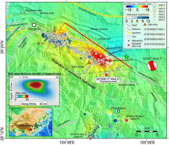
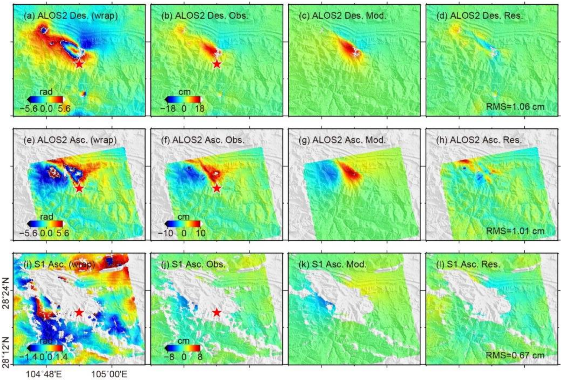
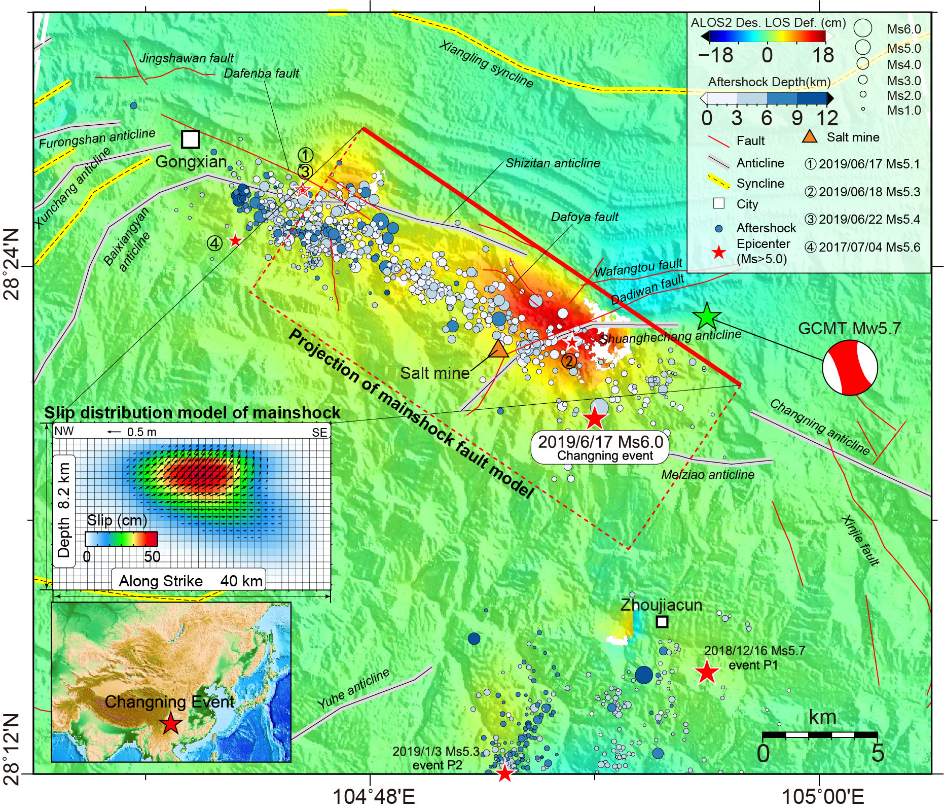
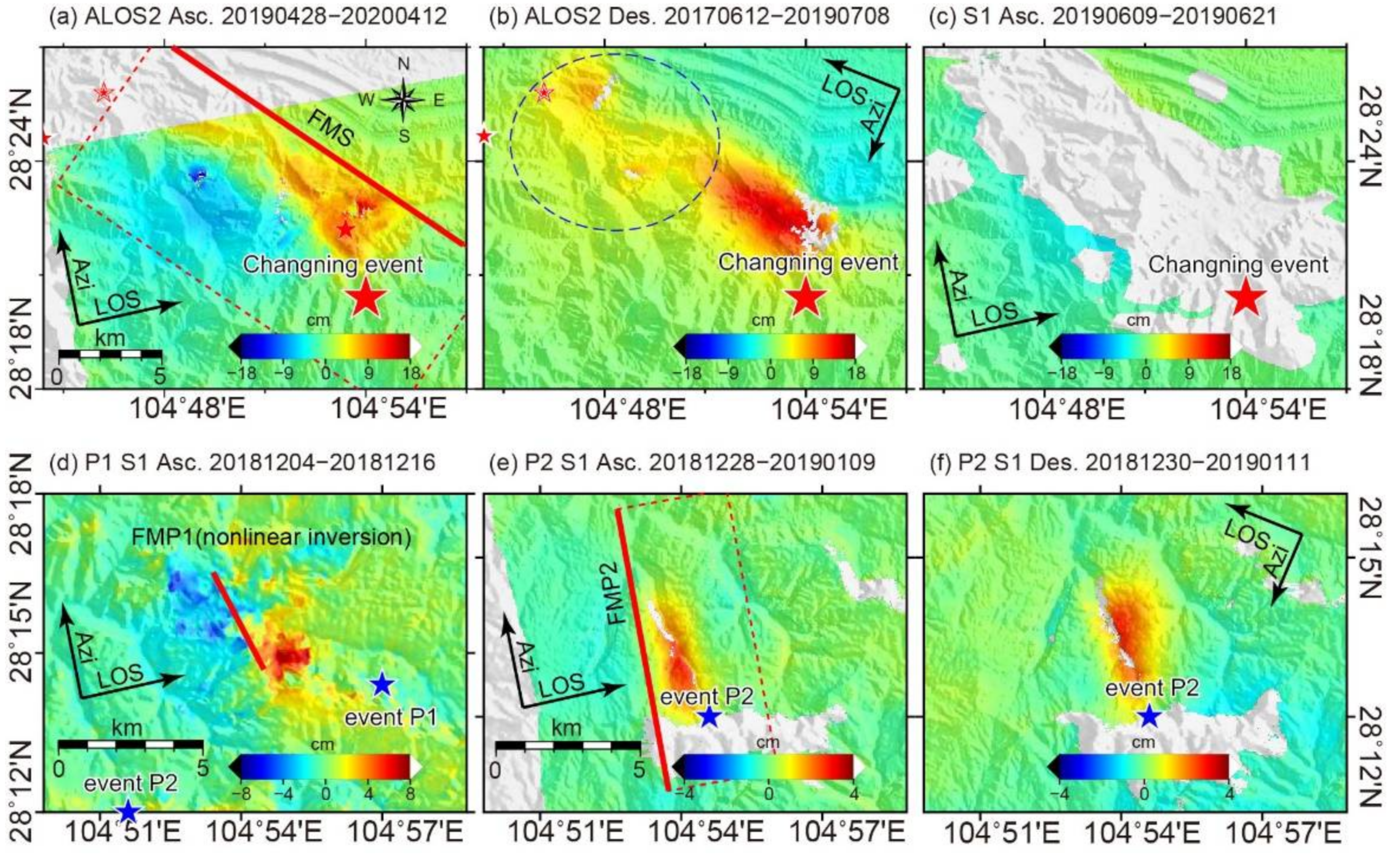
  • The Changning earthquake caused a deformation area of about 150 km2 with a maximum of 17.2 cm (LOS) in the northwest of the epicenter.
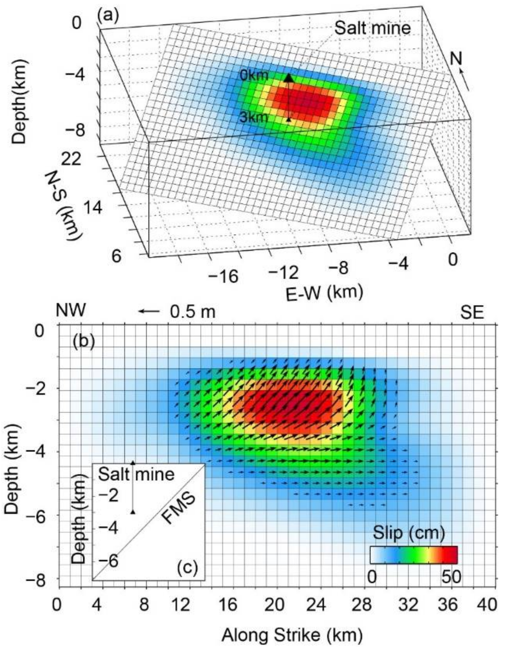
  • The Changning earthquake is a unidirectional rupture earthquake with left-lateral slip and thrust components. P1 is a pure left-lateral event, and P2 is dominated by thrust slip.
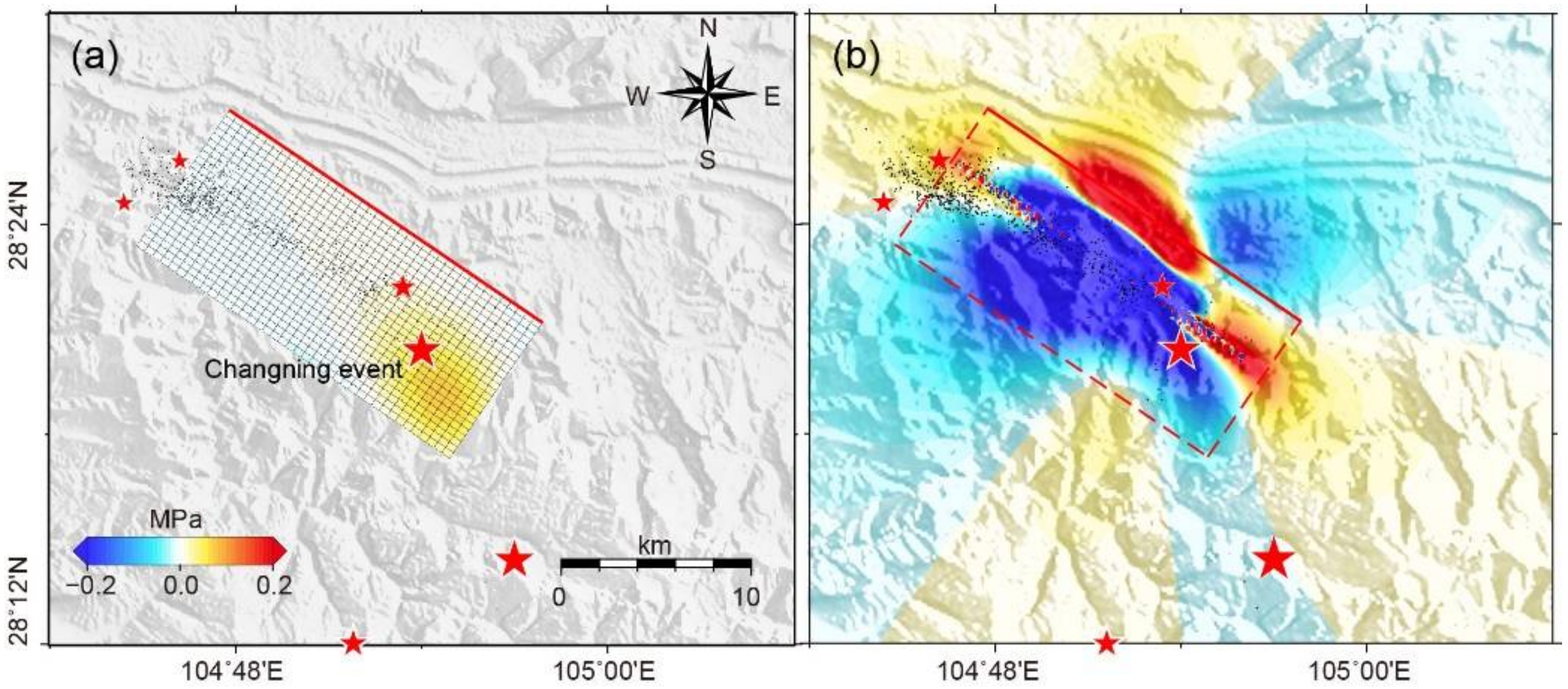
  • There is no direct evidence to suggest that the Changning earthquake is related to hydraulic fracturing. We infer that the Changning earthquake may be advanced by salt mining, but P1 and P2 may also play an important role in advancing the Changning earthquake.
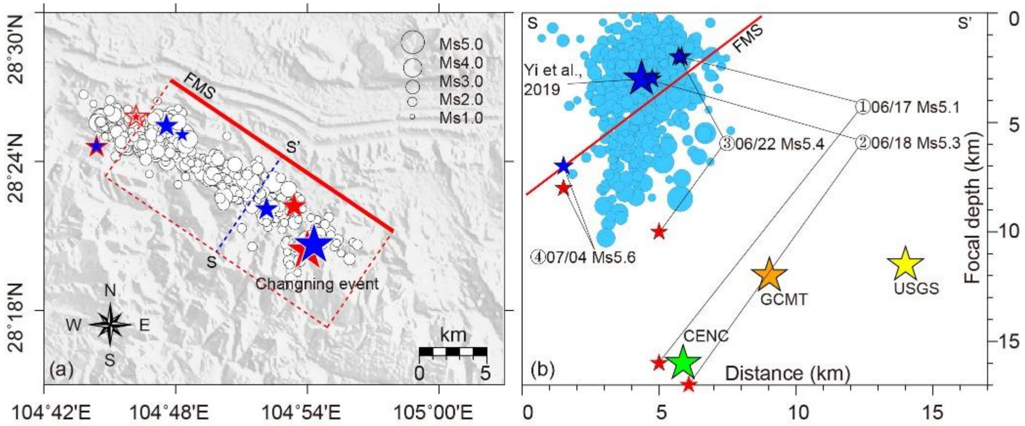
  • The characteristics of aftershock distribution indicate that the seismic activities may be controlled by crust heterogeneity and structural complexity.
In this study, we analyzed the relationship between salt mining and the Changning earthquake from time and space correlation, but there is a lack of an accurate model for quantitative analysis. In future research, we may conduct more systematic and in-depth research from the triggered seismic model of water pumping and injection.

Supplementary Materials

The supplementary material is available online; it contains one text and seven figures. The following supporting information can be downloaded at: https://www.mdpi.com/article/10.3390/rs14092082/s1, Text S1: the Monte Carlo analysis of FMS; Figure S1: The co-seismic deformation and coherence of the Changning event observed by Sentinel-1 and ALOS2; Figure S2: The deformation points participating in inversion after quadtree sampling; Figure S3: The Monte Carlo analysis result of FMS; Figure S4: Three-dimensional and two-dimensional slip models of P2; Figure S5: The accumulated water loss of salt mines in 2000–2013 and the expected loss in 2014–2020; Figure S6: The deformation caused by 22 June 2019 Ms 5.4 and 4 July 2019 Ms 5.6 events; and Figure S7: The observed deformation, forward deformation, and residuals of P1 and P2.

Author Contributions

Conceptualization, H.G. and M.L.; methodology, H.G.; software, H.G.; resources, W.X. and N.F.; writing—original draft preparation, H.G. and X.L.; writing—review and editing, H.G., M.L. and X.L.; supervision, M.L. All authors have read and agreed to the published version of the manuscript.

Funding

This work was funded by the National Key Research and Development Program of China, grant number 2019YFC1509201. The National Natural Science Foundation of China (Grant No. 41904001), the China Postdoctoral Science Foundation (Grant No. 2018M640733), and the National Postdoctoral Program for Innovative Talents (Grant No. BX20180220).

Data Availability Statement

Not applicable.

Acknowledgments

We thank our editor and anonymous reviewers for their careful reading and constructive comments. We thank Yi Guixi for the catalog of relocated aftershocks. We thank Wang Shuai for stimulating discussion on data processing. We also thank Wu Fang for her revision and suggestions on the language. Some of the images in this study were drawn using the Generic Mapping Tools (GMT) which is open-source software. The Sentinel-1 images are from Copernicus Open Access Hub (https://scihub.copernicus.eu/ accessed on 20 April 2022) of the European Space Agency (ESA). The ALOS2 data are provided by Japan Aerospace Exploration Agency (JAXA) (http://en.alospasco.com accessed on 20 April 2022) (Nos. ER2A2N016 and ER2A2N161). The seismic data were provided by China Earthquake Networks Center (CENC, http://www.cenc.ac.cn/, in Chinese accessed on 20 April 2022), the U. S. Geological Survey (USGS, https://earthquake.usgs.gov/earthquakes/search/ accessed on 20 April 2022), and The Global Centroid-Moment-Tensor Project (GCMT, http://www.globalcmt.org accessed on 20 April 2022). The Okada code package can be found at https://pangea.stanford.edu/research/CDFM/software/disloc3d0.1.zip accessed on 20 April 2022. The Coulomb 3.3 software is available for free at https://pubs.usgs.gov/of/2011/1060/ accessed on 20 April 2022.

Conflicts of Interest

The authors declare no conflict of interest.

References

  1. Yi, G.X.; Long, F.; Liang, M.J.; Zhao, M.; Wang, S.W.; Gong, Y.; Qiao, H.Z.; Su, J.R. Focal mechanism solutions and seisogenic structure of the 17 June 2019 Ms6.0 Sichuan Changning earthquake sequence. Chin. J. Geophys. 2019, 62, 3432–3447. [Google Scholar] [CrossRef]
  2. Jiang, D.; Zhang, S.; Ding, R. Surface deformation and tectonic background of the 2019 Ms 6.0 Changning earthquake, Sichuan Basin, SW China. J. Asian Earth Sci. 2020, 200, 104493. [Google Scholar] [CrossRef]
  3. Ruan, X.; Cheng, W.Z.; Zhang, Y.J.; Li, J.; Chen, Y. Research of the earthquakes induced by water injections in salt mines in Changning, Sichuan. Earthq. Res. China 2008, 24, 226–234. [Google Scholar]
  4. Sun, X.; Yang, P.; Zhang, Z. A study of earthquakes induced by water injection in the Changning salt mine area, SW China. J. Asian Earth Sci. 2017, 136, 102–109. [Google Scholar] [CrossRef]
  5. Lei, X.; Wang, Z.; Su, J. The December 2018 ML 5.7 and January 2019 ML 5.3 earthquakes in South Sichuan basin induced by shale gas hydraulic fracturing. Seismol. Res. Lett. 2019, 90, 1099–1110. [Google Scholar] [CrossRef]
  6. Lei, X.; Wang, Z.; Su, J. Possible link between long-term and short-term water injections and earthquakes in salt mine and shale gas site in Changning, south Sichuan Basin, China. Earth Planet. Phys. 2019, 3, 510–525. [Google Scholar] [CrossRef]
  7. The six unit of the first district survey team of the Sichuan Provincial Geological Bureau. The Geological Report of the Junlian Region. 1973. Available online: http://www.ngac.cn/125cms/c/qggnew/index.htm (accessed on 20 April 2022). (In Chinese).
  8. Ellsworth, W.L. Injection-induced earthquakes. Science 2013, 341, 1225942. [Google Scholar] [CrossRef]
  9. Sumy, D.F.; Cochran, E.S.; Keranen, K.M.; Wei, M.; Abers, G.A. Observations of static Coulomb stress triggering of the November 2011 M5. 7 Oklahoma earthquake sequence. J. Geophys. Res. Solid Earth 2014, 119, 1904–1923. [Google Scholar] [CrossRef]
  10. He, D.F.; Lu, R.Q.; Huang, H.Y.; Wang, X.S.; Jiang, H.; Zhang, W.K. Tectonic and geological setting of the earthquake hazards in the Changning shale gas development zone, Sichuan Basin, SW China. Pet. Explor. Dev. 2019, 46, 1051–1064. [Google Scholar] [CrossRef]
  11. Liu, J.; Zahradník, J. The 2019 MW 5.7 Changning Earthquake, Sichuan Basin, China: A Shallow Doublet with Different Faulting Styles. Geophys. Res. Lett. 2020, 47, e2019GL085408. [Google Scholar] [CrossRef] [Green Version]
  12. Wang, S.; Jiang, G.; Weingarten, M.; Niu, Y. InSAR evidence indicates a link between fluid injection for salt mining and the 2019 Changning (China) earthquake sequence. Geophys. Res. Lett. 2020, 47, e2020GL087603. [Google Scholar] [CrossRef]
  13. Li, T.; Sun, J.; Bao, Y.; Zhan, Y.; Shen, Z.K.; Xu, X.; Lasserre, C. The 2019 Mw 5.8 Changning, China earthquake: A cascade rupture of fold-accommodation faults induced by fluid injection. Tectonophysics 2021, 801, 228721. [Google Scholar] [CrossRef]
  14. McGarr, A.; Simpson, D.; Seeber, L.; Lee, W. Case histories of induced and triggered seismicity. Int. Geophys. Ser. 2002, 81, 647–664. Available online: https://earthquake.usgs.gov/static/lfs/research/induced/McGarr-Simpson-Seeber-2002-International-Geophysics.pdf (accessed on 20 April 2022).
  15. Gan, W.; Zhang, P.; Shen, Z.K.; Niu, Z.; Wang, M.; Wan, Y.; Zhou, D.; Cheng, J. Present-day crustal motion within the Tibetan Plateau inferred from GPS measurements. J. Geophys. Res. Solid Earth 2007, 112, B08416. [Google Scholar] [CrossRef] [Green Version]
  16. Sun, B. Characteristics of Structural Deformation and Fluid Activity in Changning Area and Its’ Perphery, Southern Sichuan. Master′s Thesis, Chengdu University of technology, Chengdu, China, 2018. Available online: https://kns.cnki.net/KCMS/detail/detail.aspx?dbname=CMFD201901&filename=1018259172.nh (accessed on 20 April 2022). (In Chinese).
  17. Feng, G.; Li, Z.; Xu, B.; Shan, X.; Zhang, L.; Zhu, J. Coseismic deformation of the 2015 M w 6.4 Pishan, China, earthquake estimated from Sentinel-1A and ALOS2 data. Seismol. Res. Lett. 2016, 87, 800–806. [Google Scholar] [CrossRef]
  18. Xu, B.; Li, Z.; Feng, G.; Zhang, Z.; Wang, Q.; Hu, J.; Chen, X. Continent-wide 2-D co-seismic deformation of the 2015 Mw 8.3 Illapel, Chile earthquake derived from Sentinel-1A data: Correction of azimuth co-registration error. Remote Sens. 2016, 8, 376. [Google Scholar] [CrossRef] [Green Version]
  19. Xu, W.B.; Feng, G.C.; Meng, L.S.; Zhang, A.L.; Ampuero, J.P.; Bürgmann, R.; Fang, L.H. Transpressional rupture cascade of the 2016 Mw 7.8 Kaikoura earthquake, New Zealand. J. Geophys. Res. Solid Earth 2018, 123, 2396–2409. [Google Scholar] [CrossRef]
  20. Wang, L.Y.; Gao, H.; Feng, G.C.; Xu, W.B. Source parameters and triggering links of the earthquake sequence in central Italy from 2009 to 2016 analyzed with GPS and InSAR data. Tectonophysics 2018, 744, 285–295. [Google Scholar] [CrossRef]
  21. Zhang, L.; Liao, M.S.; Balz, T.; Shi, X.G.; Jiang, Y.N. Monitoring landslide activities in the three gorges area with multi-frequency satellite SAR data sets. In Modern Technologies for Landslide Monitoring and Prediction; Springer: Berlin/Heidelberg, Germany, 2015; pp. 181–208. [Google Scholar]
  22. Liao, M.S.; Zhang, L.; Shi, X.G.; Jiang, Y.N.; Dong, J.; Liu, Y.Z. Method and Practice of Landslide Deformation Monitoring by Radar Remote Sensing; Science Press: Beijing, China, 2017. [Google Scholar]
  23. Gao, H.; Liao, M.S.; Liang, X.; Feng, G.C.; Wang, G.H. Co-seismic and post-seismic fault kinematics of the 22 July 2020, Nima (Tibet) Ms6. 6 earthquake: Implications of the forming mechanism of the active N-S-trending grabens in Qiangtang, Tibet. Tectonics 2022, 41, e2021TC006949. [Google Scholar] [CrossRef]
  24. Wegmuller, U.; Werner, C. Retrieval of vegetation parameters with SAR interferometry. IEEE Trans. Geosci. Remote Sens. 1997, 35, 18–24. [Google Scholar] [CrossRef]
  25. Farr, T.G.; Rosen, P.A.; Caro, E.; Crippen, R.; Duren, R.; Hensley, S.; Kobrick, M.; Paller, M.; Rodriguez, E.; Roth, L.; et al. The shuttle radar topography mission. Rev. Geophys. 2007, 45, RG2004. [Google Scholar] [CrossRef] [Green Version]
  26. Costantini, M. A novel phase unwrapping method based on network programming. IEEE Trans. Geosci. Remote Sens. 1998, 36, 813–821. [Google Scholar] [CrossRef]
  27. Jónsson, S.; Zebker, H.; Segall, P.; Amelung, F. Fault slip distribution of the 1999 Mw 7.1 Hector Mine, California, earthquake, estimated from satellite radar and GPS measurements. Bull. Seismol. Soc. Am. 2002, 92, 1377–1389. [Google Scholar] [CrossRef]
  28. Gao, H.; Liao, M.; Feng, G. An Improved Quadtree Sampling Method for InSAR Seismic Deformation Inversion. Remote Sens. 2021, 13, 1678. [Google Scholar] [CrossRef]
  29. Okada, Y. Surface deformation due to shear and tensile faults in a half-space. Bull. Seismol. Soc. Am. 1985, 75, 1135–1154. [Google Scholar] [CrossRef]
  30. Okada, Y. Internal deformation due to shear and tensile faults in a half-space. Bull. Seismol. Soc. Am. 1992, 82, 1018–1040. [Google Scholar] [CrossRef]
  31. Eberhart, R.; Kennedy, J. Particle swarm optimization. Proc. IEEE Int. Conf. Neural Netw. 1995, 4, 1942–1948. Available online: http://citeseerx.ist.psu.edu/viewdoc/download?doi=10.1.1.931.1264&rep=rep1&type=pdf (accessed on 20 April 2022).
  32. Paatero, P.; Tapper, U. Positive matrix factorization: A non-negative factor model with optimal utilization of error estimates of data values. Environmetrics 1994, 5, 111–126. [Google Scholar] [CrossRef]
  33. Li, X.; Wang, C.; Zhu, C.; Wang, S.; Li, W.; Wang, L.; Zhu, W. Coseismic Deformation Field Extraction and Fault Slip Inversion of the 2021 Yangbi MW 6.1 Earthquake, Yunnan Province, Based on Time-Series InSAR. Remote Sens. 2022, 14, 1017. [Google Scholar] [CrossRef]
  34. Metropolis, N.; Ulam, S. The monte carlo method. J. Am. Stat. Assoc. 1949, 44, 335–341. [Google Scholar] [CrossRef]
  35. Lin, J.; Stein, R.S. Stress triggering in thrust and subduction earthquakes and stress interaction between the southern San Andreas and nearby thrust and strike-slip faults. J. Geophys. Res. Solid Earth 2004, 109, B02303. [Google Scholar] [CrossRef] [Green Version]
  36. Toda, S.; Stein, R.S.; Richards-Dinger, K.; Bozkurt, S.B. Forecasting the evolution of seismicity in southern California: Animations built on earthquake stress transfer. J. Geophys. Res. Solid Earth 2005, 110, B05S16. [Google Scholar] [CrossRef]
  37. McGarr, A. Maximum magnitude earthquakes induced by fluid injection. J. Geophys. Res. Solid Earth 2014, 119, 1008–1019. [Google Scholar] [CrossRef]
  38. Zhang, B.; Lei, J.; Zhang, G. Seismic evidence for influences of deep fluids on the 2019 Changning Ms 6.0 earthquake, Sichuan basin, SW China. J. Asian Earth Sci. 2020, 200, 104492. [Google Scholar] [CrossRef]
  39. Yang, Y.H.; Hu, J.C.; Chen, Q.; Lei, X.; Zhao, J.; Li, W.; Xu, R.; Chiu, C.-Y. Shallow slip of blind fault associated with the 2019 M S 6.0 Changning earthquake in fold-and-thrust belt in salt mines of Southeast Sichuan, China. Geophys. J. Int. 2021, 224, 909–922. [Google Scholar] [CrossRef]
  40. Lockner, D.A.; Beeler, N.M. Premonitory slip and tidal triggering of earthquakes. J. Geophys. Res. Solid Earth 1999, 104, 20133–20151. [Google Scholar] [CrossRef]
  41. Qian, H.; Tang, R.C. Seismo-geological features of the Sichuan Basin. Earthq. Res. Sichuan 1992, 3, 13–18. [Google Scholar]
  42. Bao, X.; Eaton, D.W. Fault activation by hydraulic fracturing in western Canada. Science 2016, 354, 1406–1409. [Google Scholar] [CrossRef]
  43. Schultz, R.; Atkinson, G.; Eaton, D.W.; Gu, Y.J.; Kao, H. Hydraulic fracturing volume is associated with induced earthquake productivity in the Duvernay play. Science 2018, 359, 304–308. [Google Scholar] [CrossRef] [Green Version]
  44. Segall, P. Stress and subsidence resulting from subsurface fluid withdrawal in the epicentral region of the 1983 Coalinga earthquake. J. Geophys. Res. Solid Earth 1985, 90, 6801–6816. [Google Scholar] [CrossRef]
  45. McGarr, A. On a possible connection between three major earthquakes in California and oil production. Bull. Seismol. Soc. Am. 1991, 81, 948–970. [Google Scholar]
  46. Wilson, M.P.; Foulger, G.R.; Gluyas, J.G.; Davies, R.J.; Julian, B.R. HiQuake: The human-induced earthquake database. Seismol. Res. Lett. 2017, 88, 1560–1565. [Google Scholar] [CrossRef] [Green Version]
  47. Ellsworth, W.L.; Giardini, D.; Townend, J.; Ge, S.M.; Shimamoto, T. Triggering of the Pohang, Korea, Earthquake (Mw 5.5) by Enhanced Geothermal System Stimulation. Seismol. Res. Lett. 2019, 90, 1844–1858. [Google Scholar] [CrossRef]
  48. Grigoli, F.; Cesca, S.; Rinaldi, A.P.; Manconi, A.; Lopez-Comino, J.A.; Clinton, J.F.; Westaway, R.; Cauzzi, C.; Dahm, T.; Wiemer, S. The November 2017 Mw 5.5 Pohang earthquake: A possible case of induced seismicity in South Korea. Science 2018, 360, 1003–1006. [Google Scholar] [CrossRef] [Green Version]
  49. Kim, K.H.; Ree, J.H.; Kim, Y.; Kim, S.; Kang, S.Y.; Seo, W. Assessing whether the 2017 Mw 5.4 Pohang earthquake in South Korea was an induced event. Science 2018, 360, 1007–1009. [Google Scholar] [CrossRef] [Green Version]
  50. Proctor, B.; Lockner, D.A.; Kilgore, B.D.; Mitchell, T.M.; Beeler, N.M. Direct evidence for fluid pressure, dilatancy, and compaction affecting slip in isolated faults. Geophys. Res. Lett. 2020, 47, e2019GL086767. [Google Scholar] [CrossRef]
  51. Utsu, T. A statistical study on the occurrence of aftershocks. Geophys. Mag. 1961, 30, 521–605. [Google Scholar]
  52. Stein, R.S.; King, G.C.; Lin, J. Change in failure stress on the southern San Andreas fault system caused by the 1992 magnitude= 7.4 Landers earthquake. Science 1992, 258, 1328–1332. [Google Scholar] [CrossRef]
  53. Huang, H.; Xu, W.; Meng, L.; Bürgmann, R.; Baez, J.C. Early aftershocks and afterslip surrounding the 2015 Mw 8.4 Illapel rupture. Earth Planet. Sci. Lett. 2017, 457, 282–291. [Google Scholar] [CrossRef] [Green Version]
  54. Liu, X.G.; Xu, W.B. Logarithmic Model Joint Inversion Method for Coseismic and Postseismic Slip: Application to the 2017 Mw 7.3 Sarpol Zahāb Earthquake, Iran. J. Geophys. Res. Solid Earth 2019, 124, 12034–12052. [Google Scholar] [CrossRef] [Green Version]
  55. Li, W.; Ni, S.; Zang, C.; Chu, R. Rupture Directivity of the 2019 M w 5.8 Changning, Sichuan, China, Earthquake and Implication for Induced Seismicity. Bull. Seismol. Soc. Am. 2020, 110, 2138–2153. [Google Scholar] [CrossRef]
  56. Métois, M.; Vigny, C.; Socquet, A.; Delorme, A.; Morvan, S.; Ortega, I.; Valderas-Bermejo, C.-M. GPS-derived interseismic coupling on the subduction and seismic hazards in the Atacama region, Chile. Geophys. J. Int. 2014, 196, 644–655. [Google Scholar] [CrossRef] [Green Version]
  57. Zhang, Z.W.; Long, F.; Wang, S.Y.; Gong, Y.; Wu, P.; Wang, H.; Jiang, G.M. Earthquake location and velocity structure in Yibin area, Sichuan. Seismol. Geol. 2019, 41, 913–926. [Google Scholar]
  58. Howarth, J.D.; Barth, N.C.; Fitzsimons, S.J.; Richards-Dinger, K.; Clark, K.J.; Biasi, G.P.; Cochran, U.A.; Langridge, R.M.; Berryman, K.R.; Sutherland, R. Spatiotemporal clustering of great earthquakes on a transform fault controlled by geometry. Nat. Geosci. 2021, 14, 314–320. [Google Scholar] [CrossRef]
  59. Sathiakumar, S.; Barbot, S. The stop-start control of seismicity by fault bends along the Main Himalayan Thrust. Commun. Earth Environ. 2021, 2, 87. [Google Scholar] [CrossRef]
  60. Kato, A.; Obara, K. Step-like migration of early aftershocks following the 2007 Mw 6.7 Noto-Hanto earthquake, Japan. Geophys. Res. Lett. 2014, 41, 3864–3869. [Google Scholar] [CrossRef]
Figure 1. Geotectonic background and aftershocks distribution of the Changning earthquake. White dotted frames denote the SAR data coverage. Red stars are the epicenters of the Ms > 5 earthquakes which occurred from 16 December 2018 to 4 July 2019 (CENC). Green star is the epicenter of the Changning event from the Global Centroid-Moment-Tensor (GCMT, https://www.globalcmt.org/, accessed on: 20 April 2022). Blue dots in the middle of the figure are the aftershocks of the Changning event [1] and those inside the blue ellipse are that of P1 and P2 [6]. Orange triangle is the salt mine near the epicenter [3]. Red frames are the surface projection of the fault models inverted in Section 3.2 and the solid line represents the top of the model. The faults and folds in the map are revised from [1] and the geological report of the Junlian region [7].
Remotesensing 14 02082 g001
Figure 2. The coseismic deformation of the Changning event (ac), P1 (d), and P2 (e,f) obtained from the ALOS2 and Sentinel-1 data. The background color represents the surface deformation. Warm color represents the surface moving toward the satellite and cold color represents moving away from the satellite. The red and blue stars in the figures are the epicenters (CENC). The red dotted frame is the surface projection of the fault models inverted in Section 3.2. FMS is the fault model of the mainshock. FMP1 and FMP2 are the models of P1 and P2, respectively. The area in the blue dashed ellipse is the deformation caused by aftershocks.
Remotesensing 14 02082 g002
Figure 3. (a) Three-dimensional and (b) two-dimensional slip models of the Changning event. (c) Side view of (a). Each small rectangle in the figures represents a slip patch. The color of the patch indicates the slip value and the arrow represents the slip direction. Black triangles indicate the locations of the salt mine and well.
Remotesensing 14 02082 g003
Figure 4. InSAR observations either wrapped (a,e,i), or unwrapped (b,f,j), forward deformation (c,g,k), and residuals (d,h,l) of the Changning event based on FMS. Figures (a) and (e) are re-wrapped with a period of 11.2 cm. Figure (i) is re-wrapped with a period of 2.8 cm.
Remotesensing 14 02082 g004
Figure 5. (a) Coulomb stress changes on the fault of the Changning event caused by the slip in the P1 and P2 events. (b) Coulomb stress changes in the earthquake area after the Changning event. The reference depth is 3.2 km (the average depth of all aftershocks). The small black dots are aftershocks from Yi et al. [1] and the small stars are the epicenters of Ms > 5.0 aftershock (CENC).
Remotesensing 14 02082 g005
Figure 6. (a) The distribution of aftershocks and the surface projections of FMS. (b) Cross-section along the blue dotted line in panel a. The white dots in (a) and blue dots in (b) are the relocated aftershocks provided by Yi et al. [1]. The big stars are the epicenters of the Changning event and the small stars are Ms > 5.0 aftershocks. Red, blue, yellow, and orange stars are the results of CENC, Yi et al. [1], USGS, and GCMT, respectively.
Remotesensing 14 02082 g006
Table 1. Image information processed by D-InSAR.
EventDate
Day-Month-Year
SatelliteOrbitPrimary
Day-Month-Year
Secondary
Day-Month-Year
Perpendicular Baseline (m)Pass
P116-Dec-18Sentinel-1Asc4-Dec-1816-Dec-181555
P23-Jan-19Sentinel-1Asc28-Dec-189-Jan-1912355
Sentinel-1Des30-Dec-1811-Jan-199164
Changning17-Jun-19Sentinel-1Asc9-Jun-1921-Jun-192955
ALOS2Asc28-Apr-1912-Apr-2040146
ALOS2Des12-Jun-178-Jul-196937
Aftershock ➂22-Jun-19Sentinel-1Asc21-Jun-193-Jul-192155
Aftershock ➃4-Jul-19Sentinel-1Asc3-Jul-1915-Jul-192855
Table 2. The fault parameters of Changning, P1, and P2 events from different sources.
EventSourceLon./°Lat./°Depth/kmStrike/°Dip/°Rake/°MwNote
ChangningThis study (a)104.85528.3724.1 *12443405.65/
Yi et al. [1]104.90528.3443 **13151365.79Plane 1
Wang et al. [12]//1 *12131/5.69Uniform slip model
CENC (b)104.90028.34016 **/////
USGS (c)104.93328.40611.5 **31465625.81Plane 1
GCMT (d)104.95028.38012 *11787−25.7Plane 1
P1This study (e)104.90128.2581.7 *33389−15.15/
Yi et al. [1]104.94828.2193 **34976−55.17Plane 2
CENC104.95028.24012 **/////
USGS105.01328.29517.5 **34983−35.28Plane 2
GCMT105.09028.20014 *34884−95.3Plane 2
P2This study (f)104.85628.2242.3 *34950874.81/
Yi et al. [1]104.86128.1922 **35146464.81Plane 2
CENC104.86028.20015 */////
USGS104.91828.19011.5 *35548594.85Plane 2
GCMT104.95028.21012 **34941435Plane 1
(a), (e), (f), the parameters obtained in this study are the optimal results of 100 times non-linear inversion. The epicenter parameters (including longitude, latitude, and depth) of this study are all the mass centers of the faults. (b) China Earthquake Networks Center. (c) the U. S. Geological Survey. (d) the Global Centroid-Moment-Tensor. * the depth of the mass center. ** the depth of sources.
Publisher’s Note: MDPI stays neutral with regard to jurisdictional claims in published maps and institutional affiliations.

