Article

BDS/GPS/UWB Adaptively Robust EKF Tightly Coupled Navigation Model Considering Pedestrian Motion Characteristics

1
School of Geoscience and Surveying Engineering, China University of Mining and Technology-Beijing (CUMTB), Beijing 100083, China
2
School of Geomatics and Urban Spatial Informatics, Beijing University of Civil Engineering and Architecture (BUCEA), Beijing 102616, China
*
Author to whom correspondence should be addressed.
Remote Sens. 2022, 14(8), 1940; https://doi.org/10.3390/rs14081940
Submission received: 22 February 2022 / Revised: 21 March 2022 / Accepted: 12 April 2022 / Published: 17 April 2022

Abstract

:
In the indoor and outdoor transition area, due to its poor availability in a complex positioning environment, the BDS/GPS SPP (single-point positioning by combining BeiDou Navigation Satellite System (BDS) and Global Positioning System (GPS)) is unable to provide an effective positioning service. In view of the poor positioning accuracy and low sampling rate of the BDS/GPS SPP and the gross error, such as the non-line-of-sight error of UWB (Ultra-Wide-Band), making the accuracy of positioning results poor, a BDS/GPS/UWB tightly coupled navigation model considering pedestrian motion characteristics is proposed to make positioning results more reliable and accurate in the transition area. The core content of this paper is divided into the following three parts: (1) Firstly, the dynamic model and positioning theories of BDS/GPS SPP and UWB are introduced, respectively. (2) Secondly, the BDS/GPS/UWB tightly coupled navigation model is proposed. An environment discrimination factor is introduced to adaptively adjust the variance factor of the system state. At the same time, the gross error detection factor is constructed by using the a posteriori residuals to make the variance factor of the measurement information of the combined positioning system able to be adjusted intelligently for the purpose of eliminating the interference of gross error observations on positioning results. On the other hand, pedestrian motion characteristics are introduced to establish the constraint equation to improve the consistency of positioning accuracy. (3) Thirdly, the actual measured data are used to demonstrate and analyze the reliability of the positioning model proposed by this paper. The experimental results show that the BDS/GPS/UWB tightly coupled navigation model can effectively improve the accuracy and availability of positioning. Compared with BDS/GPS SPP, the accuracy of this model is improved by 57.8%, 76.0% and 56.5% in the E, N and U directions, respectively.

1. Introduction

In recent years, with the acceleration of modern urban infrastructure construction and indoor space development, seamless indoor and outdoor positioning technology has attracted extensive attention, and pedestrian positioning in the transition area is the premise and foundation of realizing indoor and outdoor seamless positioning. The multi-sensor fusion positioning technology based on filtering has developed rapidly over recent years to improve the availability and continuity of positioning under complex scenes. However, due to the heterogeneity of data, there are still some problems in the accurate acquisition of the filter measurement model and state model.
GNSS (Global Navigation Satellite Positioning) positioning technology, which can provide positioning, navigation and timing, has been widely used in intelligent driving, disaster monitoring and other fields [1,2]. However, when the GNSS receiver is located in a complex positioning scene, the GNSS signal is easily interrupted, resulting in GNSS being unable to provide accurate location information [3]. To improve the reliability and availability of satellite positioning results in complex scenes, with the continuous development of GNSS modernization and intellectualization, multi-system GNSS data processing has become a trend. Multi-system heterogeneous data-combined positioning can effectively improve the observable number of satellites so as to solve the problem of the poor availability of single-system satellite positioning [4]. GNSS positioning technology can be divided into single-point positioning (SPP), precision-point positioning (PPP), RTK (Real-Time Kinematic) and PPP-RTK according to the positioning mode and positioning accuracy [5,6,7,8,9]. Because RTK positioning technology obtains the high-precision baseline information of rover stations through differential processing of data between the base station and rover station [10], it cannot meet the needs of single-station operation. PPP positioning technology must rely on high-precision satellite position information and clock error information; it uses high-precision distance observations, such as carrier phase observations, to obtain centimeter-level positioning results [11], but there are still some problems in its convergence speed and real-time performance. In recent years, some scholars proposed to use information, such as atmospheric parameters, generated by local GNSS reference stations to help fix the ambiguity of PPP, so as to realize the fast fixing of PPP ambiguity. This technology is called PPP-RTK [12,13,14]. Considering the actual needs of pedestrian positioning accuracy, BDS/GPS SPP (single-point positioning by combining BeiDou Navigation Satellite System (BDS) and Global Positioning System (GPS)) is used in the pedestrian GNSS/UWB-integrated positioning system in the transition area to ensure the timeliness and low cost of positioning.
With the development of UWB (Ultra-Wide-Band) technology, compared with GNSS positioning technology, UWB positioning technology has the advantage of high positioning accuracy and good availability in the sheltered area of urban high-rise buildings [15]. However, the non-line-of-sight (NLOS) phenomenon that is easy to observe in the process of UWB measurement will make the ranging UWB value have a systematic deviation from the reference value. The NLOS distance means that the propagation path is blocked by dynamic and static obstacles, resulting in longer propagation time and a larger measured distance than the actual distance. NLOS effects will lead to frequent changes in UWB observation signal quality and affect the positioning accuracy [16]. To correctly detect and eliminate UWB NLOS multipath error, machine learning, deep learning, numerical analysis and other methods are used in UWB positioning to give UWB positioning results more robustness [17,18,19,20,21]. Guo et al. [22] adaptively adjusted the variance factor by constructing the evaluation factor of NLOS to improve the robustness of the model. Rayavarapu and Mahapatro [23] proposed the bagging-based ensembled classifier to identify and eliminate the impact of NLOS error on positioning results. Kim and Pyun [24] proposed a UWB NLOS error recognition algorithm based on a UWB signal propagation mechanism. Cao et al. [25] proposed a GMM-IMM-EKF model by combining a Gaussian mixed model (GMM), interacting multiple model (IMM) and EKF (Extended Kalman Filter) algorithm to eliminate the influence of NLOS error on positioning results.
Because there are many obstacles under the typical positioning field of urban positioning, the observation environment is complex and changeable, so it is difficult to provide accurate and reliable positioning services when a single sensor is used. A multi-sensor combined positioning model can improve the availability of GNSS in complex location scenarios by combining the advantages of different sensors. It provides opportunities for high-precision location services in complex location scenarios. MacGougan and O’Keefe [26] use accurate UWB ranging information to build the GPS RTK/UWB tightly coupled positioning model to make the floating-point solution more reliable and more consistent with the real value. The research results show that, compared with GPS RTK, the GPS RTK/UWB tight combination positioning algorithm can improve the fixed rate of ambiguity and the reliability of the positioning results in complex scenes [27]. Wang et al. [28] found that when the observation information is fused with UWB data and GPS data, the robustness of the model is enhanced. At the same time, aiming at the richness of multi-sensor information, the accurate construction of a fusion model is one of the key problems to realize multi-sensor high-precision positioning. Liu et al. [29] proposed to adaptively adjust the GPS and UWB variance matrix by using the Hermit variance component estimation algorithm according to different data sources. The adaptively robust EKF algorithm adjusts the random model to resist the interference of various gross errors on the positioning results, so it is used to calculate the parameters when multi-sensor positioning is carried out [30,31,32]. Li et al. [33] used an improved EKF algorithm to realize the INS/GPS/UWB tight combination, to eliminate the interference of gross error of observation values on positioning results and to identify the gross error contained in GPS/UWB, and a robust factor was constructed based on observation value residuals and the chi-square hypothesis test.
In order to make pedestrian positioning results more reliable and accurate in the transition area, a BDS/GPS/UWB adaptively robust EKF tightly coupled navigation model considering pedestrian motion characteristics is proposed in this paper to improve the positioning accuracy of the BDS/GPS SPP and correctly identify and eliminate NLOS error of UWB positioning. The core contributions of the article are as follows: (1) An environmental discrimination factor is constructed to evaluate the quality of observations, so as to realize the intelligent adjustment of the stochastic model of the Kalman filter dynamic model; (2) a gross error recognition factor based on the posterior residual is constructed to adaptively adjust variance factor of measurement information to eliminate the influence of the gross error on the positioning results; and (3) the pedestrian motion characteristics constraint factor is constructed by modeling the pedestrian motion characteristics to further improve the stability of the combined model.
This paper is divided into four sections: Section 2 introduces the BDS/GNSS/UWB tightly coupled navigation model; Section 3 demonstrates and analyzes the algorithm using the measured data; and Section 4 gives the main conclusions.

2. Methods

In order to clarify the core research content of the paper, this chapter introduces the BDS/GPS/UWB adaptively robust EKF tightly coupled navigation model considering pedestrian motion characteristics. The chapter is divided into the following three sections: (1) a dynamic model, (2) an observation model and (3) a Tightly coupled algorithm considering pedestrian motion characteristics

2.1. Dynamic Model

In view of the stable speed of pedestrian movement in the conventional state, this paper uses the constant speed Kalman filter model for BDS/GPS/UWB-integrated positioning. X k = [ x k , y k , z k , v x , k , v y , k , v z , k , d t r , i s b r s ] T indicates the parameter to be estimated; x k , y k , z k v x , k , v y , k and v z , k represent the pedestrian position and speed in the x , y and z directions at time k , respectively; and d t r , i s b r s represents the difference between the receiver clock and the reference time and the time reference difference between different satellite systems; then, the dynamic model of the BDS/GPS/UWB tightly coupled navigation is [32]:
X k = φ X k 1 + w k
where X k and X k 1 represent the values of the parameters to be estimated at time k and time k − 1; φ is the state transformation matrix (see Equation (2) for its specific form; t is the sampling interval); w k is the system disturbance factor, which conforms to the white noise distribution; and Q k is the variance–covariance matrix of w k . The specific form can be found in Equation (2) [31]:
{ φ = [ 1 0 0 t 0 0 0 0 0 1 0 0 t 0 0 0 0 0 1 0 0 t 0 0 0 0 0 1 0 0 0 0 0 0 0 0 1 0 0 0 0 0 0 0 0 1 0 0 0 0 0 0 0 0 1 0 0 0 0 0 0 0 0 1 ] T Q k = [ 0.05 t 3 3 I 3 × 3 0.05 t 2 2 I 3 × 3 0 3 × 1 0 3 × 1 0.05 t 2 2 I 3 × 3 0.05 t I 3 × 3 0 3 × 1 0 3 × 1 0 1 × 3 0 1 × 3 3600 0 0 1 × 3 0 1 × 3 0 3600 ]
Considering the instability of the difference between the receiver clock and the reference time and the time reference difference between different satellite systems, the white noise model is used to estimate them.

2.2. Observation Model

2.2.1. BDS/GPS SPP Considering TGD Correction

Without loss of generality, by refining various errors, the BDS/GPS pseudo-range-positioning equation is expressed as follows [33]:
p r s , k = ρ r s , k + T r s , k + I r s , k + d t r + α i s b r s d t s , k + B P
where r , s , k represent the receiver, satellite system and satellite PRN, respectively; p r s , k is the BDS/GPS ranging value; ρ r s , k is the geometric distance between the satellite and the station; T r s , k is the tropospheric delay; I r s , k is the ionospheric delay; d t r is the receiver clock error; i s b r s is the inter-system bias; α is the coefficient of the inter-system bias (when GPS is used as the reference system, the value is 0 for GPS; for BDS, the value is 1); and d t s , k is the satellite clock error. The research shows that for a single epoch, the hardware delay of the receiver is consistent for all satellites, and this is highly related to the receiver clock difference. Therefore, in the process of BDS/GPS SPP, the hardware delay deviation of the receiver is often combined with the receiver clock difference [34]. Therefore, the above equation only represents the hardware delay deviation of the satellite.
As one of the refinement error terms of BDS/GPS SPP, the influence of B P on ranging accuracy can reach meter level, so it must be corrected in BDS/GPS SPP. When GPS pseudo-ranges are adopted, they can be expressed as follows:
B P = T G D
where T G D is the timing group delay provided by GPS broadcast ephemeris.
When using the pseudo-range positioning of BDS B1I frequency, since the reference frequency of BDS broadcast ephemeris is B3I, there is a pseudo-range hardware delay in the pseudo-range, which can be expressed as follows:
B P = T G D B 1 I B 3 I
where T G D B 1 I B 3 I is the timing group delay provided by BDS broadcast ephemeris.
Figure 1 shows the BDS/GPS SPP positioning result sequence of a one-day dataset of the CUT0 station. Taking the positioning error in the E, N and U directions as the accuracy evaluation index, the influence of the TGD error correction term on the positioning results of BDS/GPS SPP is compared and analyzed. The conclusion that after the TGD correction of BDS/GPS SPP, the positioning accuracy of E, N and U is improved and that the level of improvement is at the meter level can be obtained.
After taking TGD correction into account, the observation model based on BDS/GPS observation values can be obtained according to Equation (3). We linearize Equation (3) to obtain the coefficient matrix of the measurement equation based on satellite observations:
H = [ x r x 1 ρ r 1 y r y 1 ρ r 1 z r z 1 ρ r 1 0 0 0 1 α x r x 2 ρ r 2 y r x 2 ρ r 2 z r z 2 ρ r 2 0 0 0 1 α x r x n ρ r n y r x n ρ r n z r z n ρ r n 0 0 0 1 α ]
where ρ r i ( i = 1 , 2 , , n ) is the approximate distance from the receiver to the satellite, ( x i , y i , z i ) represents the satellite coordinates, ( x r , y r , z r ) represents the value of the parameter to be calculated after updating the status and α is the intersystem bias coefficient (for GPS, the value is 0; for BDS, the value is 1).

2.2.2. Observation Model Based on the UWB Ranging Value

The UWB ranging mode adopts the TOA (Time of Arrival) ranging model [32]. The function model established using UWB ranging observations can be expressed as:
P r , k i = ( x u w b x i ) 2 + ( y u w b y i ) 2 + ( z u w b z i ) 2
where P r , k i is sensor ranging value; x u w b , y u w b , z u w b are the equipment locations; and x i , y i , z i are the locations of the base stations.
Taylor expansion is applied to Equation (7) to find the linear coefficient matrix H k of the observation model:
H k = [ x r x 1 ρ r 1 y r y 1 ρ r 1 z r z 1 ρ r 1 0 0 0 x r x 2 ρ r 2 y r y 2 ρ r 2 z r z 2 ρ r 2 0 0 0 x r x n ρ r n x r x n ρ r n z r z n ρ r n 0 0 0 ]
where ρ r i ( i = 1 , 2 , , n ) is the calculated distance.
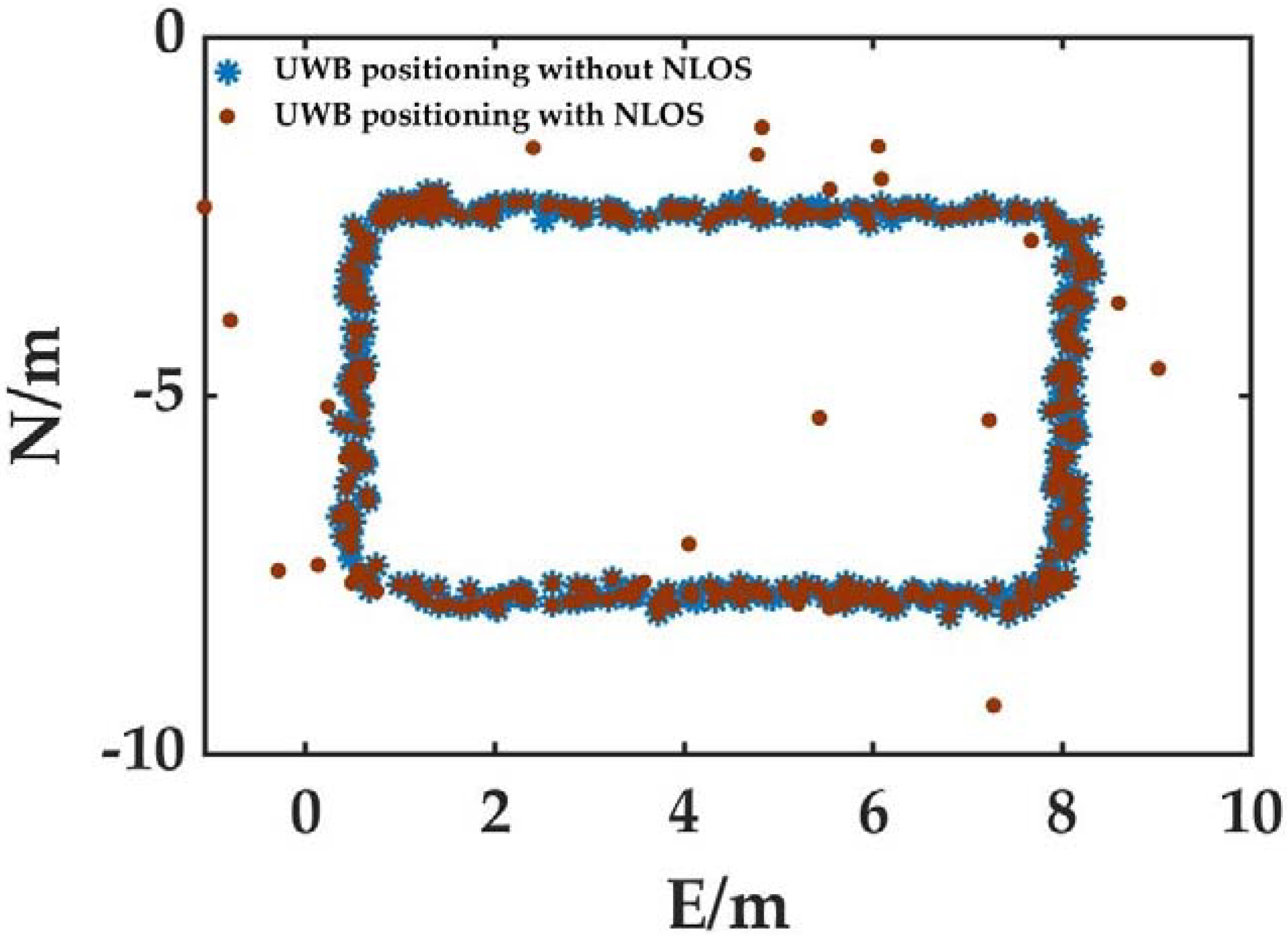
It can be seen from the equation that since the UWB ranging adopts the TOA ranging model, the UWB signal is easily disturbed in the propagation process, which will lead to NLOS error in the original distance observation. Figure 2 shows a pure UWB positioning simulation experiment based on the measured data in an open scene (where the red track represents the positioning results after adding obvious NLOS error; black represents the positioning results which is obtained by using the original observation values). Through the analysis of Figure 2, it is obvious that when there is an NLOS error, there exist obvious errors between the positioning results obtained by pedestrians and the reference value. Therefore, when the observation model includes the UWB ranging value, it is necessary to add gross error detection and an elimination algorithm to identify the observations containing NLOS error from the total observations.

2.3. Tightly Coupled Algorithm Considering Pedestrian Motion Characteristics

2.3.1. BDS/GPS/UWB-integrated Combination Algorithm Based on EKF

The optimal estimation of state parameters of the BDS/GPS/UWB tightly coupled navigation model based on EKF contains two modules: (1) the time update and (2) the measurement update [30]. The time update is:
X ¯ k = A k X k 1
P ¯ k = A k P k 1 A k T + Q k 1
When the observation value of BDS/GPS Z k is obtained, the state parameters are updated using the measurement information as follows, according to Equations (3) and (7):
V ¯ = Z k f ( X ¯ k )
P V ¯ = H k P ¯ k H k T + R k
K = P ¯ k H k T P V ¯ 1
X k = X ¯ k + K V k | k 1
P k = ( I K H k ) P ¯ k ( I K H k ) T + K R k K T
where P k 1 and P k indicate the variance factor of parameters to be estimated at time k 1 and k , respectively; X k 1 and X k represent the optimal estimated value of parameters at time k 1 and time k , respectively; X ¯ k means the prediction value of parameters; Q k 1 is the system variance factor; P ¯ k is the variance of the predicted value of the parameter to be estimated; R k is the variance corresponding to the observation value obtained by the sensors; V ¯ is the innovation factor; P V is its covariance; and K is the gain factor [32].

2.3.2. Adaptive Filtering Model

Due to the complexity of the positioning environment and the uncertainty of pedestrian trajectory, there are obvious differences in the accuracy of the dynamic model under different observation conditions. In order to realize the adaptive adjustment of the dynamic model with different positioning environments, according to the characteristics of the high ranging accuracy of the UWB ranging signal without NLOS, this paper constructs an environmental discrimination factor with the innovation vector of the UWB observation to realize the intelligent recognition of the complexity of the positioning scene in the transition area:
β = { 1 n 3   &   λ < χ 0.01 , n 2 0 o t h e r s
where β is the environmental discrimination factor, the number of effective UWB observations is n and χ 0.01 , n 2 represents the critical value of the chi-square test with significance level of 0.01 and degree of freedom of n; λ is the chi-square test value constructed by the innovation vector measured by UWB, and its specific expression is:
λ = V ¯ u w b T Q u w b 1 V ¯ u w b
where V ¯ u w b represents the innovation vector of UWB observation, and Q u w b is its variance covariance matrix.
When the value of β is 1, the positioning scene is judged to be excellent, indicating that the accuracy of the observation value in the current positioning scene is high and the number of observations is sufficient. Therefore, the dynamic model should be reduced in this positioning scene, and its specific expression is:
P ¯ k | k 1 = χ 0.01 , n 2 λ P k | k 1

2.3.3. Robust Filtering Algorithm

For the high-precision ranging information value, the stability of a posteriori residual is obviously better than that of an innovation vector. Therefore, the robust filtering theory based on a posteriori residual has attracted extensive attention in recent years [35]. Considering that in the actual data acquisition, due to the complexity and variability of the positioning scene, there is an inevitable gross error factor in the original data, this paper introduces an iterative robust filtering algorithm based on the posteriori residual distribution law to realize the adaptive adjustment of observation value covariance, so as to eliminate the positioning bias caused by the interference of the gross error factor.
According to the functional relationship between the posteriori residual and the parameters to be solved, the expression of a posteriori residual V k is as follows:
V k = Z k H k X k
Bring Equations (12)–(14) into Equation (19) to obtain:
V k = R k P V ¯ k 1 V ¯ k
It can be seen that the covariance matrix of a posteriori residual is:
P V k = R k P V ¯ k 1 R k T
The excess observed component is:
r j = ( R k P V k | k 1 1 ) j j
Combining Equations (20)–(22), constructs the gross error detection factor:
v ˜ j = | V j | r j × P V k
where V j is the j component of V k .
After obtaining the gross error detection factor, the observed value equivalent variance matrix can be constructed according to the IGGIII scheme (Equation (25)):
R ¯ k , j = R k , j × γ
γ = { 1 | v ¯ j | k 0 | v ¯ j | k 0 ( k 1 k 0 k 1 | v ¯ j | ) 2 k 0 < | v ¯ j | k 1 10 20 | v ¯ j | > k 1
where R ¯ k , j is the j diagonal element of the observed value equivalent variance matrix, and k 0 and k 1 are the gross error detection test thresholds, which can be set to 1.5 and 3, respectively. In order to avoid the normal observation value being incorrectly calibrated as a gross error factor due to the error transfer, this paper constructs equivalent covariance only for the maximum a posteriori residual in the process of robust error. At the same time, in view of the limitations of single gross error detection (there may be missed detection when multiple gross error factors exist), this paper adopts the iterative robust scheme. (In order to avoid the divergence of filtering, the maximum number of iterations is set to 10.)

2.3.4. Pedestrian Motion Characteristics Constraint Algorithm

Because the road in the transition area is relatively flat, the running speed of pedestrians is relatively slow under normal conditions, and the elevation change range of the environment where pedestrians live in a short time is small, this paper constructs a constraint equation based on the motion characteristics of pedestrians:
h k = h k 1
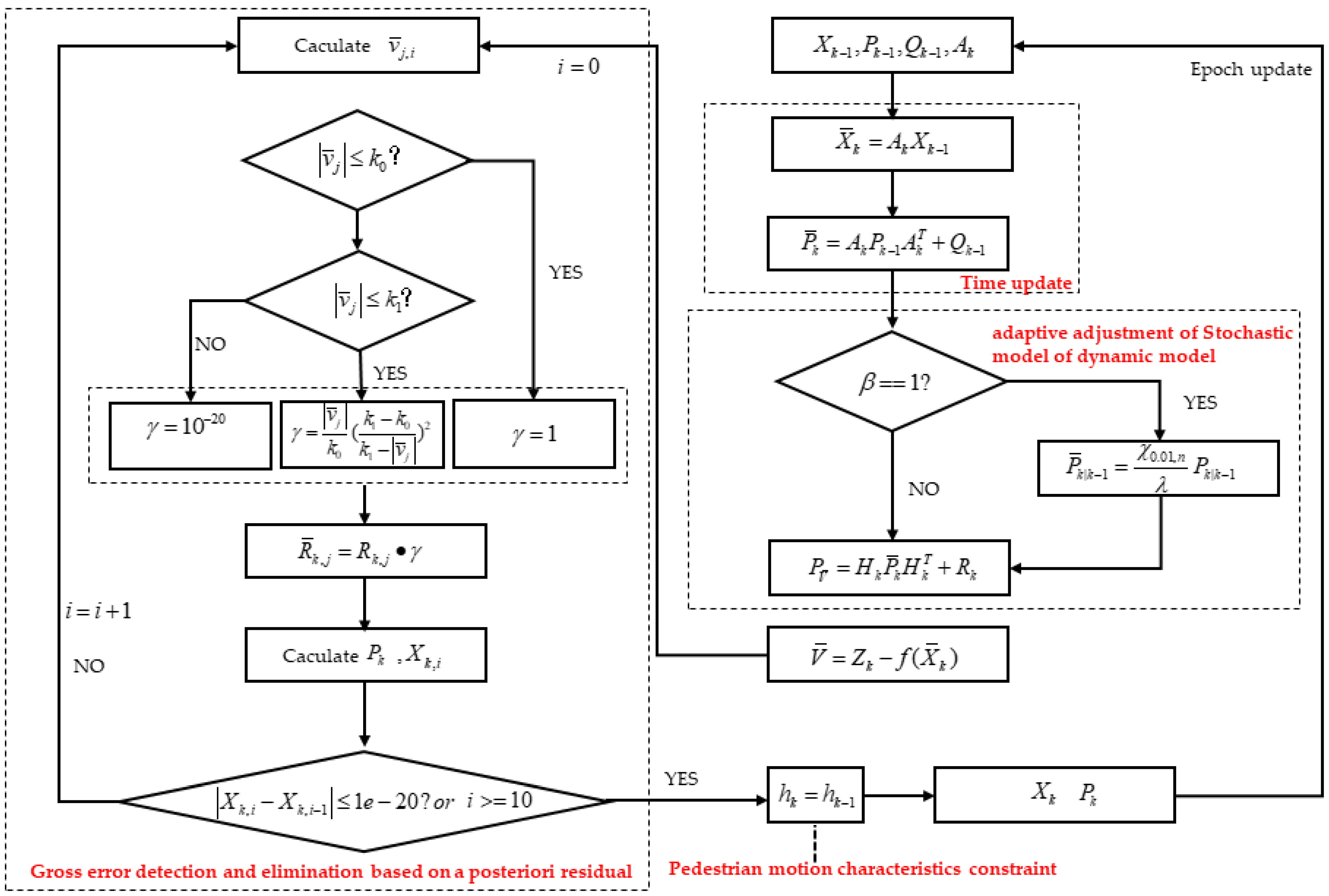
where h k , h k 1 are the elevation values of k and k 1 in the ENU coordinate system (which can be obtained by coordinate conversion). Due to the inevitable introduction of various bias factors in the positioning data process, the elevation value of the previous epoch may diverge in the solution process. At this time, applying elevation constraints may make positioning results divergence. For this problem, this paper uses the elevation variance of the previous epoch as the covariance matrix of the constraint variance. The core flow chart of the positioning model is shown in the Figure 3.

3. Results

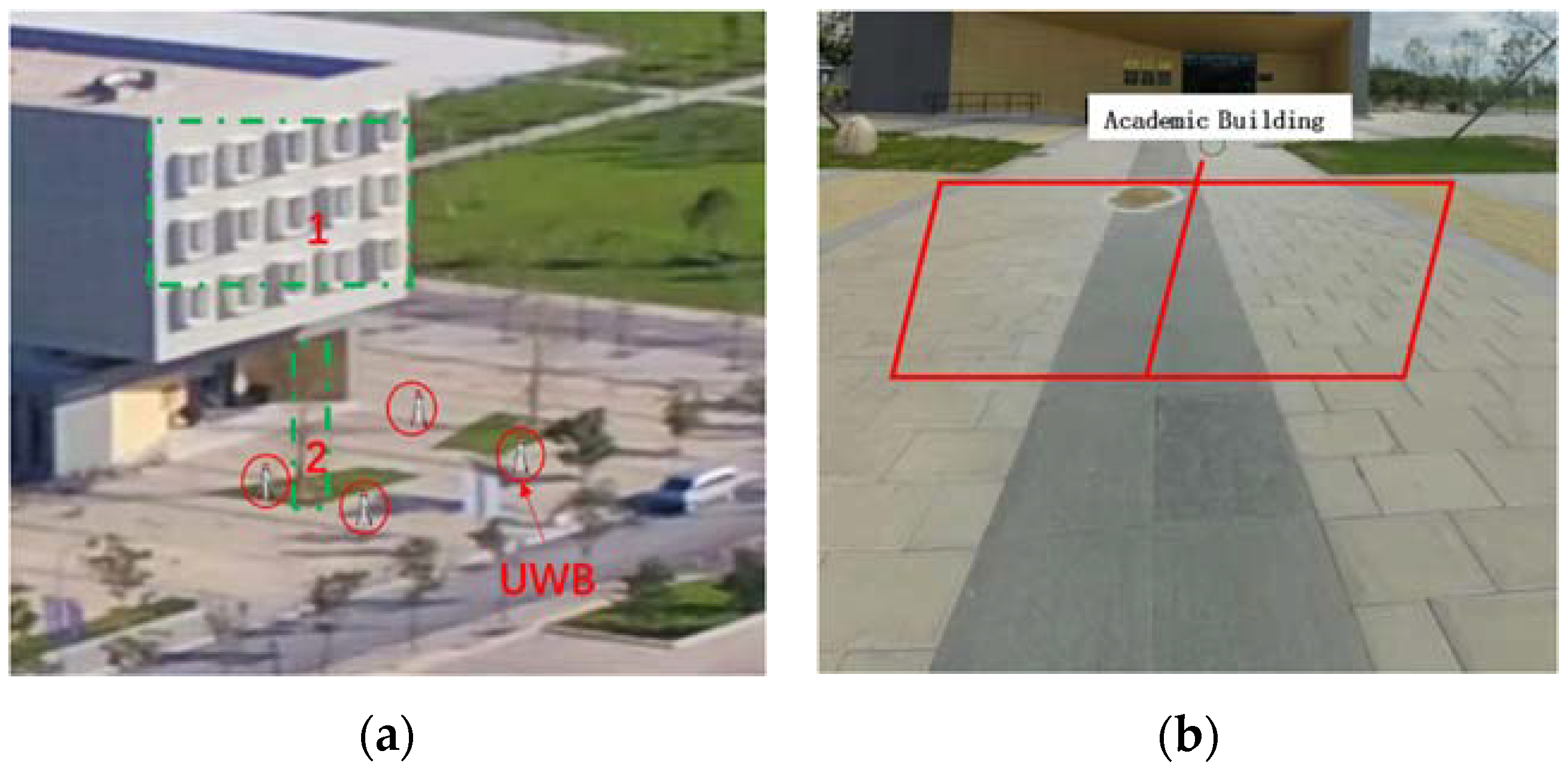
The experimental scene is located at the gate of the teaching building of Beijing University of Civil Engineering and Architecture. Firstly, four UWB positioning base stations are evenly arranged at the door of the teaching building, and then the experimenters hold the BDS/GPS/UWB hybrid positioning terminal to conduct a positioning test along the experimental design track. The specific experimental scenario is shown in Figure 4.
As shown in Figure 4, when pedestrians walk according to the design track, the BDS/GPS/UWB equipment will be unable to be located due to the blocking of the BDS/GPS signal in the areas of obstacle 1 and obstacle 2 (Arabic numerals in Figure 4a). At the same time, due to the blocking of the UWB base station in the obstacle 2 area, there will be an NLOS problem in the pedestrian UWB positioning terminal.
The pedestrian walking track is shown in Figure 4b, which is 8 m long and 6 m wide; Meanwhile, the distance between UWB base stations is 30 m. In order to evaluate the accuracy of pedestrian end positioning results, this paper uses the high-precision geodesic RTK combined positioning results as the track reference value (the positioning accuracy can be controlled within 5 cm)

3.1. BDS/GPS SPP

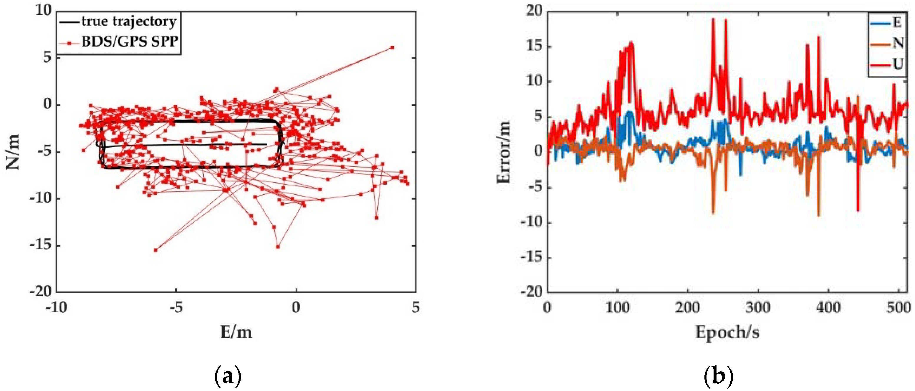
In order to demonstrate and analyze the positioning performance of BDS/GPS SPP in the transition area, this paper first uses pure BDS/GPS SPP to locate pedestrians in the transition area. The experimental results can be found in Figure 5.
Figure 5 shows the trajectory of pedestrians and biases of the BDS/GPS SPP positioning model on the three axis systems of the local coordinate system in the transition area. Due to the shielding of buildings in the transition area, the BDS/GPS satellite signal quality is poor, the data availability is low and there is an obvious bias based on BDS/GPS SPP. At the same time, when a single BDS/GPS SPP is used for pedestrian positioning in the transition area, the plane positioning accuracy is better than 5 m and the elevation positioning accuracy is better than 10 m, which can be seen from Figure 5b. Due to the problems of signal interruption and gross error observation interference of BDS/GPS in the transition area, some epoch positioning results have obvious outliers.

3.2. UWB Positioning

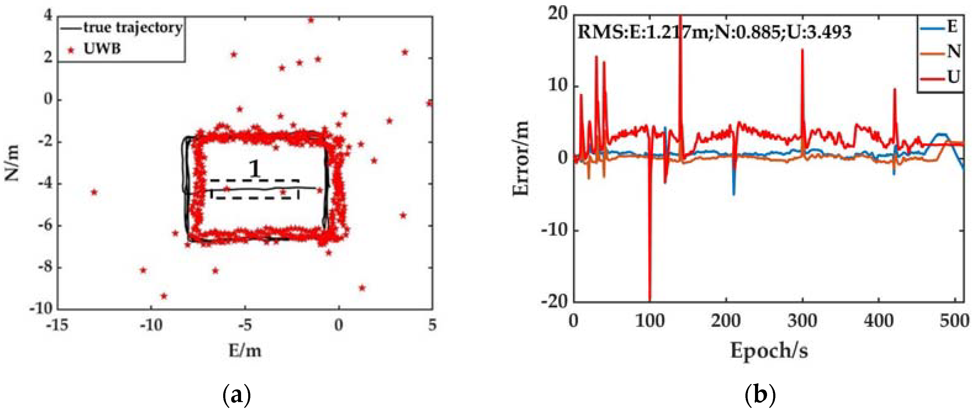
In order to evaluate the robustness and availability of UWB navigation in the transition area, this paper uses pure UWB equipment to conduct the pedestrian end positioning experiment in the transition area. To evaluate the interference degree of NLOS error on the positioning results, this paper simulates the interference of UWB ranging signal by randomly placing obstacles in the experimental process. Through the horizontal comparison of the positioning results in Figure 5, it is obvious that when the pedestrian in the transition area uses the UWB positioning terminal for positioning, due to the high-precision characteristics of UWB ranging information, the positioning result is in high compliance with the reference value when there is no NLOS (as shown in the overall trajectory in Figure 6a). At the same time, it can be seen that when there is an NLOS error in the observation value, the positioning result has serious bias compared with the true trajectory, and the degree of bias from the reference value is related to the size of the NLOS error. At the same time, due to the problems of easy interruption of the data link in the transmission process of UWB base station data, the continuity of the UWB positioning results is low (as shown in position 1 in Figure 6a). In order to further quantitatively analyze the accuracy of UWB positioning results in the presence of NLOS error, taking the root-mean-square error (RMS) as the accuracy evaluation index, this paper provides the accuracy of UWB positioning on three axis systems of a local coordinate system. According to the analysis of the index value, the UWB plane positioning accuracy is better than 1.5 m in the presence of NLOS error. However, due to the problems of poor geometric and spatial structure of the base stations and the small number of base stations in UWB positioning, the positioning accuracy of elevation direction is poor (The error of individual epochs can reach 20 m). At the same time, by further analyzing the UWB positioning trajectory and the network shape of the base station, it can be seen that the difference in the geometric space structure of the UWB base station will lead to obvious differences in the positioning accuracy of UWB in different directions.
To sum up, when pedestrians in the transition area use UWB to obtain their location information, the plane positioning results are in high conformity with the actual trajectory if there are no obvious obstacles that will introduce NLOS errors into the observation scene. However, when there is an NLOS error, the plane positioning results will deviate from the actual position, and the instantaneous deviation can reach 10 m. On the other hand, when pedestrians use single BDS/GPS sensors for positioning, due to the serious occlusion of satellite signals, the positioning results seriously deviate from the true value, which cannot meet the high-precision positioning needs of pedestrians in the transition area.

3.3. BDS/GPS/UWB Tightly Coupled Navigation

In order to evaluate the effectiveness of the BDS/GPS/UWB tightly coupled navigation model, four experiments were designed:
(1)
BDS/GPS SPP (Starting from this section, the abbreviation BDS/GPS SPP is used to represent the experiments);
(2)
BDS/GPS/UWB tightly coupled positioning based on EKF (Starting from this section, the abbreviation EKF is used to represent the experiment);
(3)
BDS/GPS/UWB tightly coupled navigation with an environmental discrimination factor (Starting from this section, the abbreviation AEKF is used to represent the experiment);
(4)
BDS/GPS/UWB tightly coupled positioning based on adaptively robust EKF with additional pedestrian motion characteristics constraints (Starting from this section, the abbreviation AREKF is used to represent the experiment).
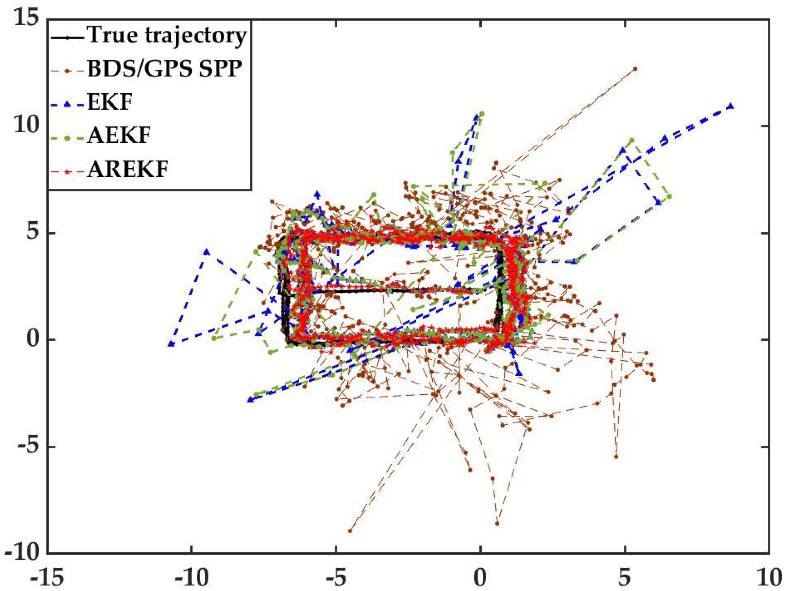
Figure 7 shows the pedestrian positioning trajectory and real trajectory in the transition area under the conditions of each experiment. As can be seen from Figure 7, when conventional EKF is used for BDS/GPS/UWB tightly coupled navigation, the positioning accuracy is improved compared with BDS/GPS SPP, and its trajectory is consistent with the reference trajectory. However, because the conventional EKF cannot adaptively adjust the dynamic model and does not have robust ability in the process of parameter solutions, the positioning bias of the filter in some epochs is too large. The adaptive EKF filter based on the environmental discrimination factor realizes the adaptive adjustment of the dynamic model by evaluating the accuracy of the dynamic model in different environments. Therefore, its positioning accuracy is obviously better than that of the conventional EKF filter. However, as can be seen from Figure 7, whether using conventional EKF or AEKF, when there are gross error factors such as UWB NLOS error in the observed values, there will be obvious bias in the positioning results; the model proposed by this paper realizes the detection and elimination of gross errors in observations by constructing a gross error detection factor on the basis of AEKF and further improves the stability of the algorithm by adding pedestrian motion features. As can be seen from Figure 7, the model in this paper can not only effectively resist the influence of the gross error of the observation value on the positioning results, but it also has the characteristics of high stability, and its positioning trajectory is highly consistent with the reference trajectory.
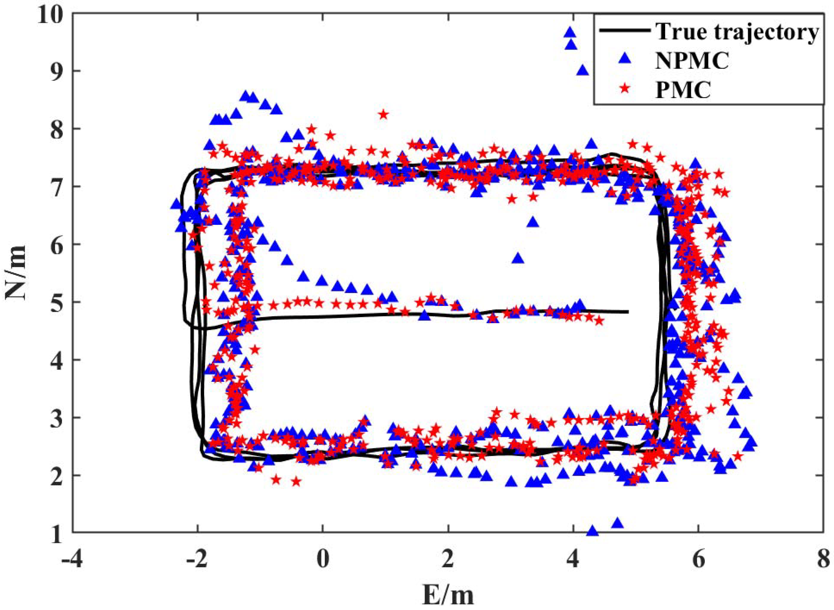
Through further analysis, it is obvious that the observability of UWB at position 1 in Figure 6a is reduced due to the problems of easy interruption of data connection during the data transmission of the UWB equipment. For the fusion positioning algorithm under these circumstances, the quality of the observation value depends on the observation value of the BDS/GPS. However, due to the problems of easy loss of data and the poor accuracy of the observation values in the transition area of the BDS/GPS, the positioning results at this position will deviate. To solve this problem, this algorithm constructs high-precision virtual observations for the fusion positioning system by adding pedestrian motion characteristics constraints, so as to further improve the robustness and universality of the algorithm. (As shown in Figure 8, NPMC (None Pedestrian Motion Characteristics) represents an adaptively robust EKF fusion algorithm without pedestrian motion characteristics constraints, and PMC (Pedestrian Motion Characteristics) represents the adaptively robust EKF fusion algorithm with additional pedestrian motion characteristics constraint information.)
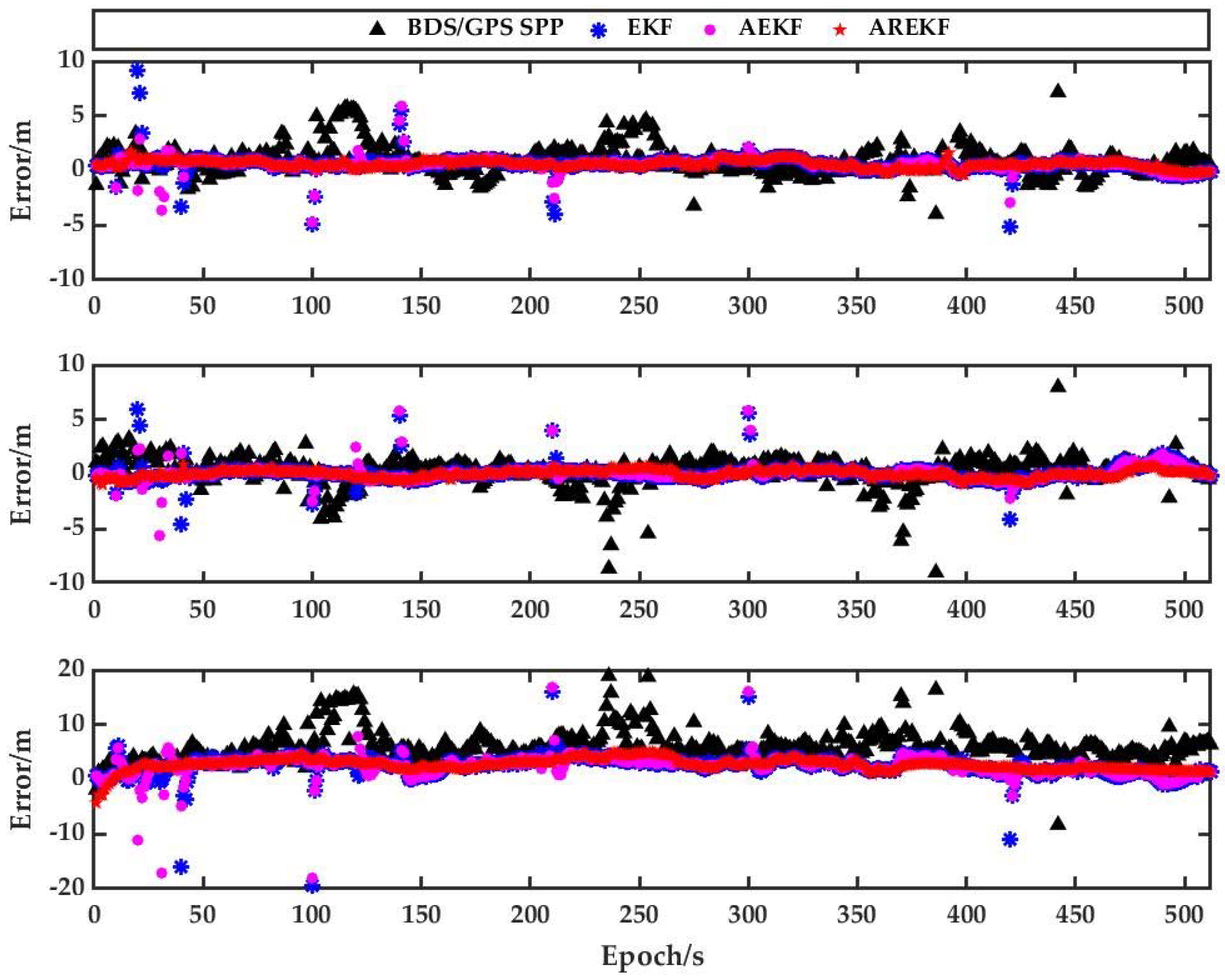
Figure 9 shows that the positioning errors of the trajectory of each scheme in the E, N and U directions are obtained by comparison with the real trajectory. Through the analysis of the positioning residuals, the conclusion is obtained that the BDS/GPS/UWB tightly coupled positioning proposed by this paper has the best positioning accuracy in any direction. The plane positioning accuracy can reach the decimeter level. At the same time, through the further analysis of Figure 9, the following information is available: When the gross error detection and recognition algorithm proposed in this paper is not used, the BDS/GPS/UWB fusion positioning algorithm has obvious outliers (for example, the positioning results of some epochs of EKF and AEKF in Figure 9 deviate significantly from the mean value); the robustness of the positioning system based on this algorithm proposed by this paper has been significantly improved compared with other positioning systems.
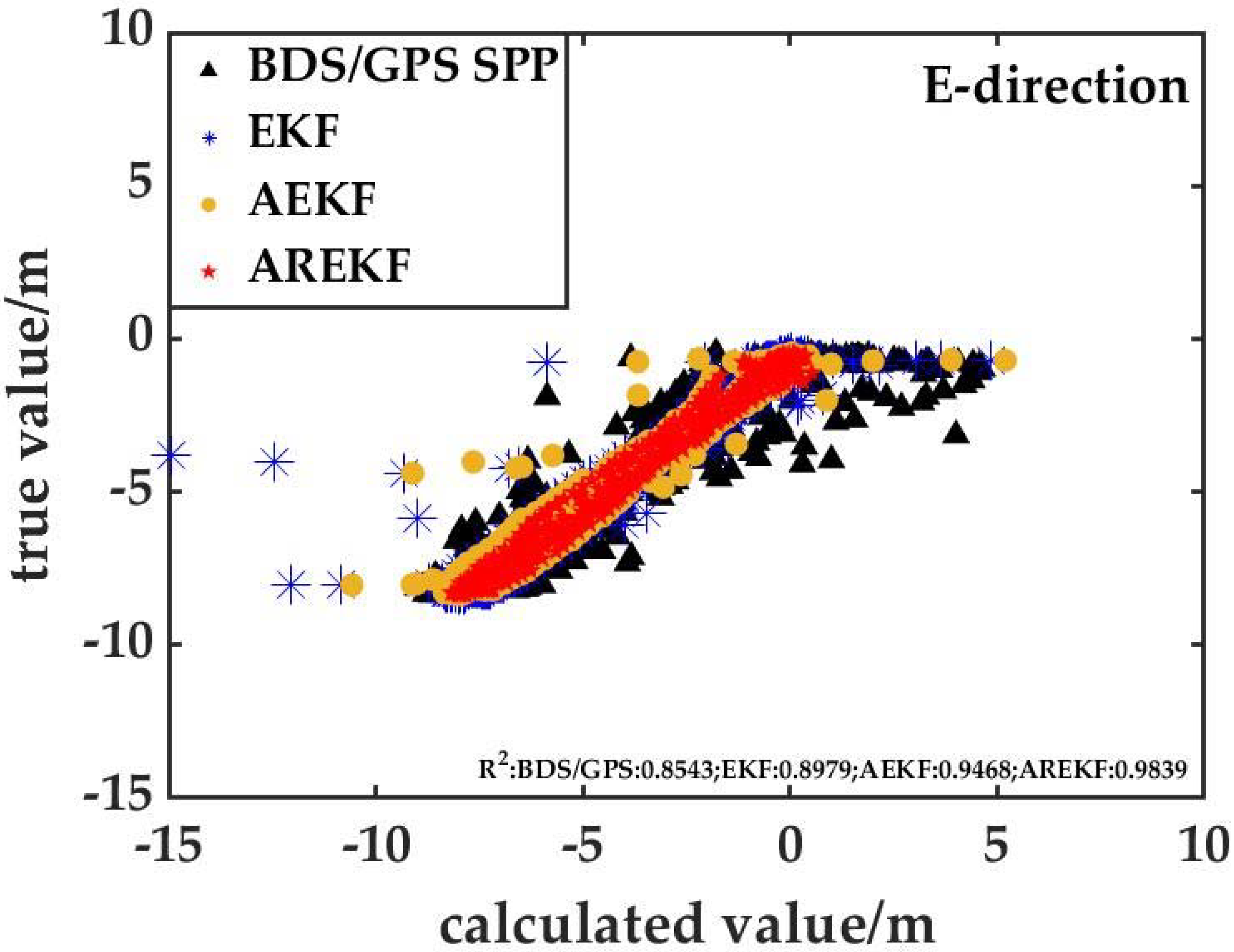
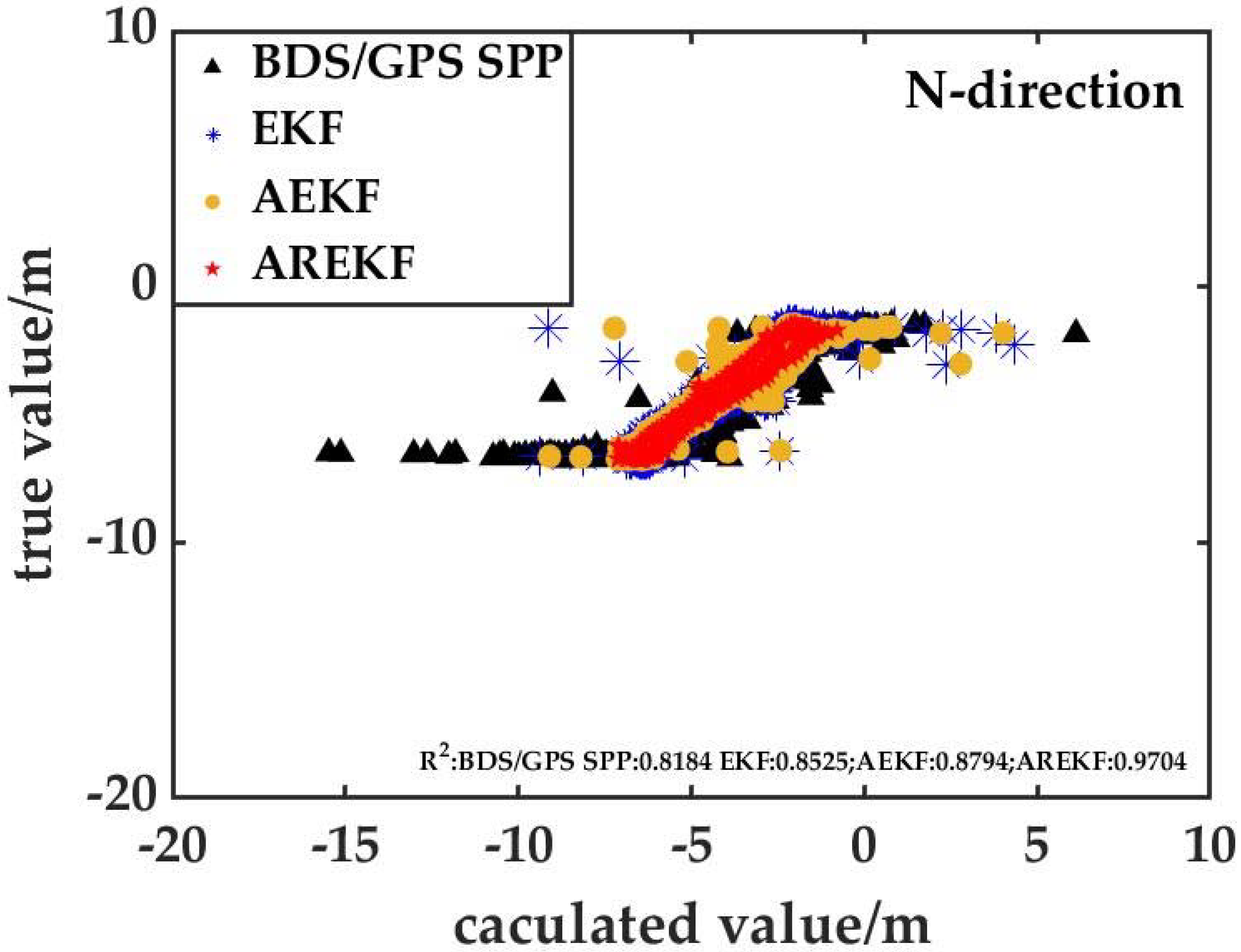
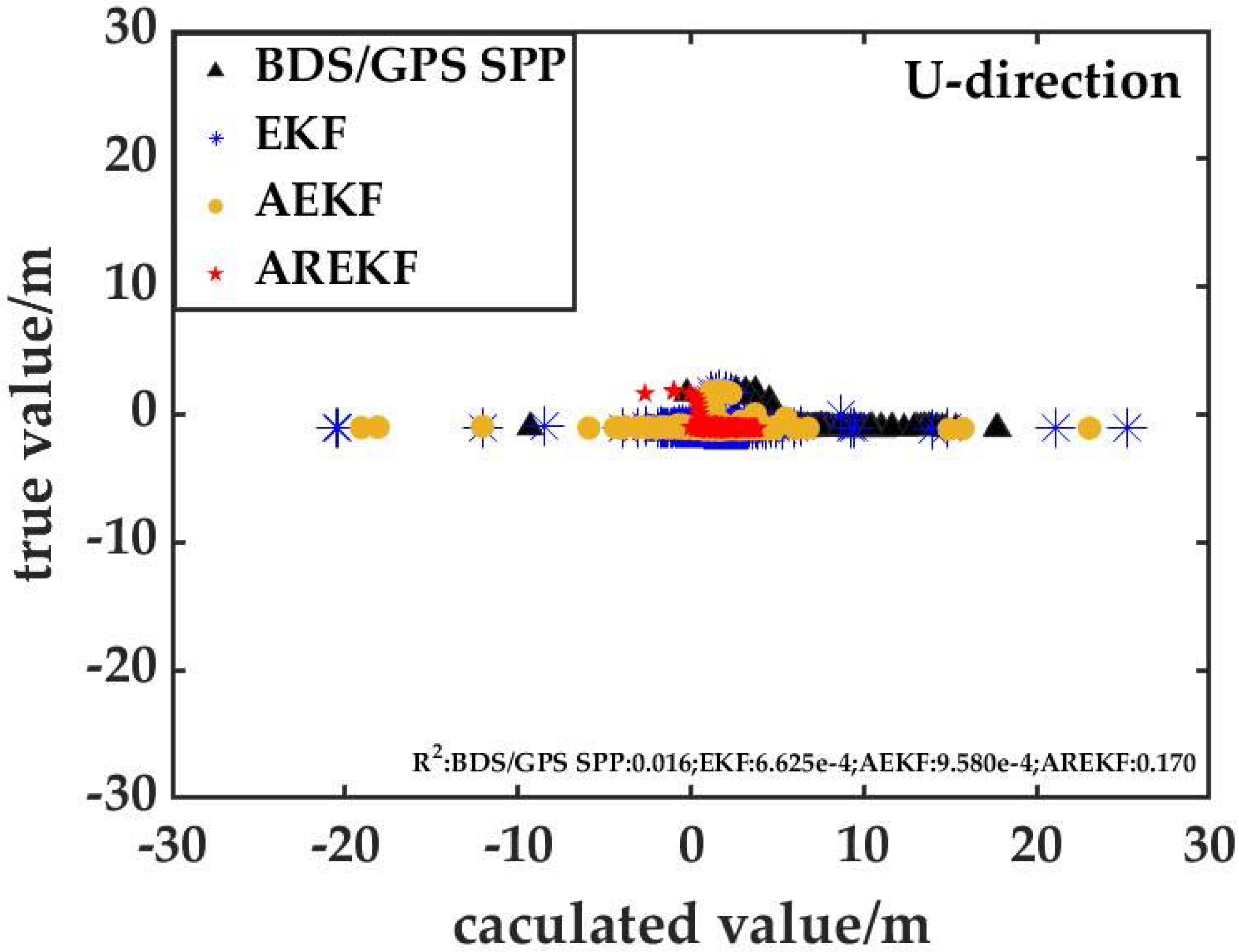
It can be seen from the analysis results (Figure 10, Figure 11 and Figure 12) that the correlation between the BDS/GPS/UWB positioning results based on the proposed algorithm in this paper and the true value is obviously better than the other three positioning algorithms, which also proves the superiority of the algorithm in this paper. At the same time, through further analysis of Figure 12, it can be seen that when pedestrian motion constraints are not attached. Due to the poor positioning accuracy of the BDS/GPS SPP and the UWB algorithms in the U direction, there are many outliers in the U direction of scheme 2 (BDS/GPS/UWB tightly coupled positioning based on EKF) and scheme 3 (BDS/GPS/UWB tightly coupled navigation with an environmental discrimination factor), which make the correlation between the positioning results of scheme 2 and scheme in the U direction and the true value poor. In addition, the true value is lower than that of the BDS/GPS SPP. Through the longitudinal comparative analysis of Figure 10 and Figure 12 or Figure 11, it can be seen that the plane positioning accuracy of each scheme is significantly higher than that in U direction, which is consistent with the results of Figure 9.
To quantify the positioning accuracy of each positioning scheme, this paper takes RMS as the accuracy evaluation index to count the accuracy values of each scheme (see Table 1). Table 1 shows that the accuracy of this algorithm proposed by this paper is significantly better than other algorithms. In the transition zone, the positioning bias in the E, N and U directions is better than 70 cm, 40 cm and 3 m, respectively. Compared with the BDS/GPS SPP algorithm, the accuracy of the E, N and U directions is improved by 57.8%, 76.0% and 56.5%, respectively. At the same time, the results show that the proposed algorithm can effectively eliminate the influence of the gross error (such as a UWB NLOS error) on the positioning results, and its positioning accuracy is improved by 44.6%, 60.5% and 17.6%, respectively, compared with the pure UWB positioning algorithm in the E, N and U directions. For the fusion navigation model, the positioning accuracy of the E direction is significantly lower than that of the N direction in the conventional EKF, AEKF and AREKF, which is highly consistent with the positioning results of pure UWB. From this analysis, it can be seen that there is an obvious correlation between the accuracy of the BDS/GPS/UWB fusion algorithm and the network shape of UWB base station.

4. Conclusions

Aiming to solve the problems of the low positioning accuracy of the BDS/GPS SPP and the influence of the gross error, such as a UWB NLOS error, on the positioning results, a BDS/GPS/UWB tightly coupled navigation model based on improved adaptively robust EKF with pedestrian motion characteristics constraints is proposed in this paper. Firstly, the environmental discrimination factor is constructed by using the mathematical characteristics of the observed values to realize the adaptive change of the dynamic model. Then, a robust factor is constructed based on the posteriori residual to resist the influence of gross error, such as NLOS error of the observation value, on the positioning results. At the same time, to improve the continuity and availability of the positioning results of the algorithm, the constraint information of pedestrian motion characteristics is constructed by exploring the physical characteristics of pedestrian motion.
In order to demonstrate the effectiveness and accuracy of the algorithm, this paper uses the measured data to carry out relevant experiments. The experimental results show that the positioning accuracy and continuity of the BDS/GPS/UWB tightly coupled navigation proposed by this paper is obviously better than that of other schemes, which effectively improved the availability and robustness of pedestrian positioning results in the transition area. At the same time, the experimental results show that the difference in the UWB base station spatial distribution will lead to the obvious difference in positioning accuracy in the E and N directions. Therefore, the authors will carry out optimization research on the spatial geometry of the UWB base station networks in order to further improve the availability of the fusion location algorithm.

Author Contributions

Conceptualization, J.Z. and J.W.; methodology, J.Z. and X.C.; software, D.Y.; validation, J.Z. and J.W.; formal analysis, D.Y.; investigation, D.Y.; resources, J.W.; data curation, J.Z.; writing—original draft preparation, J.Z.; writing—review and editing, X.C.; visualization, D.Y.; supervision, J.W.; project administration, J.W.; funding acquisition, J.W. All authors have read and agreed to the published version of the manuscript.

Funding

This research was funded by the Natural Science Fund with Project No. 41874029.

Conflicts of Interest

The authors declare no conflict of interest.

References

  1. Luo, X.M.; Lou, Y.D.; Gong, X.P.; Gu, S.F.; Chen, B.Y. Benefit of Sparse Reference Network in BDS Single Point Positioning with Single-Frequency Measurements. J. Navig. 2018, 71, 403–418. [Google Scholar] [CrossRef]
  2. Zrinjski, M.; Barković, Đ.; Matika, K. Development and Modernization of GNSS. Geod. List 2019, 73, 45–65. [Google Scholar]
  3. Li, Z.K.; Wang, R.; Gao, J.X.; Wang, J. An Approach to Improve the Positioning Performance of GPS/INS/UWB Integrated System with Two-Step Filter. Remote Sens. 2018, 10, 19. [Google Scholar] [CrossRef] [Green Version]
  4. Duong, V.; Harima, K.; Choy, S.; Laurichesse, D.; Rizos, C. An optimal linear combination model to accelerate PPP convergence using multi-frequency multi-GNSS measurements. Gps Solut. 2019, 23, 49. [Google Scholar] [CrossRef]
  5. Li, X.; Wang, X.; Liao, J.; Li, X.; Li, S.; Lyu, H. Semi-tightly coupled integration of multi-GNSS PPP and S-VINS for precise positioning in GNSS-challenged environments. Satell. Navig. 2021, 2, 1. [Google Scholar] [CrossRef]
  6. Li, B.; Zhang, Z.; Miao, W.; Chen, G.E. Improved precise positioning with BDS-3 quad-frequency signals. Satell. Navig. 2020, 1, 30. [Google Scholar] [CrossRef]
  7. Li, X.; Wang, H.; Li, S.; Feng, S.; Wang, X.; Liao, J. GIL: A tightly coupled GNSS PPP/INS/LiDAR method for precise vehicle navigation. Satell. Navig. 2021, 2, 26. [Google Scholar] [CrossRef]
  8. Barnes, D. GPS Status and Modernization; Munich Satellite Navigation Summit: Munich, Germany, 2019. [Google Scholar]
  9. CSNO. Development of the BeiDou Navigation Satellite System; Version 4.0; CSNO, China Satellite Navigation Office: Beijing, China, 2019. [Google Scholar]
  10. Enge, P.K. The Global Positioning System: Signals, measurements, and performance. Int. J. Wirel. Inf. Netw. 1994, 1, 83–105. [Google Scholar] [CrossRef]
  11. Li, T.; Wang, J.L.; Laurichesse, D. Modeling and quality control for reliable precise point positioning integer ambiguity resolution with GNSS modernization. Gps Solut. 2014, 18, 429–442. [Google Scholar] [CrossRef]
  12. Li, X.X.; Zhang, X.H.; Ge, M.R. Regional reference network augmented precise point positioning for instantaneous ambiguity resolution. J. Geod. 2011, 85, 151–158. [Google Scholar] [CrossRef]
  13. Geng, J.; Teferle, F.N.; Meng, X.; Dodson, A.H. Towards PPP-RTK: Ambiguity resolution in real-time precise point positioning. Adv. Space Res. 2011, 47, 1664–1673. [Google Scholar] [CrossRef] [Green Version]
  14. Kubo, N.; Hou, R.; Suzuki, T. Decimeter level Vehicle Navigation Combining Multi-GNSS with Existing Sensors in Dense Urban Areas. In Proceedings of the International Technical Meeting of the Institute-of-Navigation, San Diego, CA, USA, 27–29 January 2014; pp. 450–459. [Google Scholar]
  15. Giannakis, G.B. Ultra-wideband communications: An idea whose time has come. In Proceedings of the IEEE International Conference on Acoustics, Speech, and Signal Processing, Hong Kong, China, 6–10 April 2003; p. 3. [Google Scholar]
  16. Marano, S.; Gifford, W.M.; Wymeersch, H.; Win, M.Z. NLOS Identification and Mitigation for Localization Based on UWB Experimental Data. IEEE J. Sel. Areas Commun. 2010, 28, 1026–1035. [Google Scholar] [CrossRef] [Green Version]
  17. Xiao, Z.L.; Wen, H.K.; Markham, A.; Trigoni, N.; Blunsom, P.; Frolik, J. Non-Line-of-Sight Identification and Mitigation Using Received Signal Strength. IEEE Trans. Wirel. Commun. 2015, 14, 1689–1702. [Google Scholar] [CrossRef]
  18. Yang, X.F. NLOS Mitigation for UWB Localization Based on Sparse Pseudo-Input Gaussian Process. IEEE Sens. J. 2018, 18, 4311–4316. [Google Scholar] [CrossRef]
  19. Poulose, A.; Han, D.S. UWB Indoor Localization Using Deep Learning LSTM Networks. Appl. Sci. 2020, 10, 6290. [Google Scholar] [CrossRef]
  20. Poulose, A.; Emersic, Z.; Eyobu, O.S.; Han, D.S. An Accurate Indoor User Position Estimator For Multiple Anchor UWB Localization. In Proceedings of the 11th International Conference on Information and Communication Technology Convergence (ICTC)-Data, Network, and AI in the Age of Untact (ICTC), Jeju, Korea, 21–23 October 2020; pp. 478–482. [Google Scholar]
  21. Poulose, A.; Eyobu, O.S.; Kim, M.; Han, D.S. Localization error Analysis of Indoor Positioning System Based on UWB Measurements. In Proceedings of the 11th International Conference on Ubiquitous and Future Networks (ICUFN), Zagreb, Croatia, 2–5 July 2019; pp. 84–88. [Google Scholar]
  22. Guo, S.L.; Zhang, Y.T.; Gui, X.Z.; Han, L.N. An Improved PDR/UWB Integrated System for Indoor Navigation Applications. IEEE Sens. J. 2020, 20, 8046–8061. [Google Scholar] [CrossRef]
  23. Rayavarapu, V.; Mahapatro, A. NLOS identification and mitigation in UWB positioning with bagging-based ensembled classifiers. Ann. Telecommun. 2021. [Google Scholar] [CrossRef]
  24. Kim, D.H.; Pyun, J.Y. NLOS Identification Based UWB and PDR Hybrid Positioning System. IEEE Access 2021, 9, 102917–102929. [Google Scholar] [CrossRef]
  25. Cao, B.; Wang, S.B.; Ge, S.R.; Ma, X.Z.; Liu, W.L. A Novel Mobile Target Localization Approach for Complicate Underground Environment in Mixed LOS/NLOS Scenarios. IEEE Access 2020, 8, 96347–96362. [Google Scholar] [CrossRef]
  26. MacGougan, G.; O’Keefe, K. Real Time UWB Error Estimation in a Tightly-Coupled GPS/UWB Positioning System. In Proceedings of the 2009 International Technical Meeting of the Institute-of-Navigation, Anaheim, CA, USA, 26–28 January 2009; pp. 360–374. [Google Scholar]
  27. MacGougan, G.; O’Keefe, K.; Klukas, R. Tightly-coupled GPS/UWB Integration. J. Navig. 2010, 63, 1–22. [Google Scholar] [CrossRef]
  28. Wang, J.; Gao, Y.; Li, Z.K.; Meng, X.L.; Hancock, C.M. A Tightly-Coupled GPS/INS/UWB Cooperative Positioning Sensors System Supported by V2I Communication. Sensors 2016, 16, 944. [Google Scholar] [CrossRef] [PubMed]
  29. Liu, G.K.; Yuan, J.A.; Wen, Y.F.; Zhang, Y.L. Research on Seamless Positioning of Power Wearables Based on GPS/UWB Combination. In Proceedings of the IEEE International Conference on Computer and Communication Engineering Technology (CCET), Beijing, China, 18–20 August 2018; pp. 123–127. [Google Scholar]
  30. Yang, Y.; He, H.; Xu, G. Adaptively robust filtering for kinematic geodetic positioning. J. Geod. 2001, 75, 109–116. [Google Scholar] [CrossRef]
  31. Li, Z.K.; Liu, C.Y.; Gao, J.X.; Li, X. An Improved WiFi/PDR Integrated System Using an Adaptive and Robust Filter for Indoor Localization. Isprs Int. J. Geo-Inf. 2016, 5, 224. [Google Scholar] [CrossRef] [Green Version]
  32. Yuan, D.B.; Zhang, J.; Wang, J.; Cui, X.M.; Liu, F.; Zhang, Y.L. Robustly Adaptive EKF PDR/UWB Integrated Navigation Based on Additional Heading Constraint. Sensors 2021, 21, 4390. [Google Scholar] [CrossRef]
  33. Li, Z.K.; Chang, G.B.; Gao, J.X.; Wang, J.; Hernandez, A. GPS/UWB/MEMS-IMU tightly coupled navigation with improved robust Kalman filter. Adv. Space Res. 2016, 58, 2424–2434. [Google Scholar] [CrossRef]
  34. Ge, Y.L.; Zhou, F.; Sun, B.Q.; Wang, S.L.; Shi, B. The Impact of Satellite Time Group Delay and Inter-Frequency Differential Code Bias Corrections on Multi-GNSS Combined Positioning. Sensors 2017, 17, 602. [Google Scholar] [CrossRef]
  35. Zhang, X.; Guo, F.; Li, P.; Zuo, X. Real-time Quality Control Procedure for GNSS Precise Point Positioning. Geomat. Inf. Sci. Wuhan Univ. 2017, 37, 940–944, 1013. [Google Scholar]
Figure 1. CUT0 one-day BDS/GPS SPP positioning results.(where (a) represents the BDS/GPS SPP positioning error when the observation value is not corrected by TGD, and (b) represents the BDS/GPS SPP positioning error after the observation value is corrected by TGD).
Remotesensing 14 01940 g001
Figure 2. UWB simulation experiment results.
Remotesensing 14 01940 g002
Figure 3. BDS/GPS/UWB tightly coupled positioning model.
Remotesensing 14 01940 g003
Figure 4. Experimental scene of the BDS/GPS/UWB tight combination positioning. (a) Overall overview of the experimental scene. (b) Walking path.
Remotesensing 14 01940 g004
Figure 5. BDS/GPS SPP positioning results (The positioning error is the difference between BDS/GPS SPP and the reference value, which is obtained epoch by epoch). (a) Positioning trajectory. (b) Positioning error.
Remotesensing 14 01940 g005
Figure 6. Positioning results of pure UWB. (a) Positioning trajectory. (b) Positioning error.
Remotesensing 14 01940 g006
Figure 7. Pedestrian positioning trajectory in the transition area.
Remotesensing 14 01940 g007
Figure 8. Influence of pedestrian motion characteristics constraint information on positioning results.
Remotesensing 14 01940 g008
Figure 9. Positioning residuals of each scheme.
Remotesensing 14 01940 g009
Figure 10. Correlation analysis between positioning results and reference values of each positioning scheme in E-direction.
Remotesensing 14 01940 g010
Figure 11. Correlation analysis between positioning results and reference values of each positioning scheme in the N-direction.
Remotesensing 14 01940 g011
Figure 12. Correlation analysis between positioning results and reference values of each positioning scheme in U-direction.
Remotesensing 14 01940 g012
Table 1. RMS for different schemes.
SchemeE/mN/mU/m
UWB1.2170.8853.493
BDS/GPS SPP1.5981.4566.619
EKF1.0180.7743.505
AEKF0.8700.7403.411
AREKF (proposed)0.6740.3502.880
Publisher’s Note: MDPI stays neutral with regard to jurisdictional claims in published maps and institutional affiliations.