Technical Note

Robust Suppression of Deceptive Jamming with VHF-FDA-MIMO Radar under Multipath Effects

1
Air and Missile Defense College, Air Force Engineering University, Xi’an 710051, China
2
College of Information and Communication, National University of Defense Technology, Wuhan 430010, China
*
Author to whom correspondence should be addressed.
Remote Sens. 2022, 14(4), 942; https://doi.org/10.3390/rs14040942
Submission received: 14 January 2022 / Revised: 5 February 2022 / Accepted: 10 February 2022 / Published: 15 February 2022

Abstract

:
Frequency diverse array multiple-input multiple-output (FDA-MIMO) radar has received a lot of attention due to the advantages of waveform diversity. Suppression of mainlobe deceptive jamming can be effectively achieved with the degree of freedom (DOF) in the range domain. However, the existing research mainly focuses on non-coherent signals. The echo signal of VHF-FDA-MIMO radar for low elevation has its own unique characteristics. False targets cannot be suppressed with conventional beamforming methods. Thus, a signal model for VHF-FDA-MIMO radar subjected to deceptive jamming is established. The reconstruction of the covariance matrix and the estimation of the steering vector are implemented with the generalized MUSIC algorithm. In addition, a matching Capon reconstruction method is proposed to finish the robust suppression of false targets for the problem of self-cancellation in the absence of a priori information. Finally, the beampattern and performance curves of different methods are compared. The simulation results show that the methods can be effectively applied to the suppression of deceptive jamming in VHF-FDA-MIMO radar under the multipath effect.

1. Introduction

Very high frequency (VHF) radar is the radar that operates at the meter wavelength. It has received a lot of attention from researchers due to its excellent performance in anti-stealth and other aspects. However, in the scenario of detecting low elevation targets, the wide beampattern feature of the VHF radar makes the received ground reflected waves strong. As a result, it can lead to problems such as multipath coherent signals. The conventional angle measurement methods in such scenarios would be in danger of failure. The problem of parameter estimation for low elevation targets by VHF radar has long been a focus in the field of radar [1,2,3].
MIMO radar effectively enhances the degree of freedom (DOF) in the system by waveform diversity technology. Thus, it has the advantages of high resolution and high multi-target tracking capability. Then, the application of MIMO technology to the parameter estimation of VHF radar has been one of the difficulties in the research. The transmit–receive characteristics of the VHF-MIMO radar make one target correspond to four propagation paths. It makes the received signal coherent. The maximum likelihood (ML) estimation algorithm can be applied in VHF radar as a parameter estimation method that is not necessary to consider coherence. For the high computational effort in the MIMO regime, a maximum likelihood estimation method using geometric relations to reduce the dimensionality was proposed in [4]. A fast low elevation target estimation method was proposed in [5], which effectively reduces the complexity of parameter estimation for VHF-MIMO radar. To accomplish parameter estimation in complex terrain, a generalized MUSIC algorithm was proposed for robust estimation of low elevation targets [6]. Ref. [7] proposed a high-precision estimation method based on rank-1 constraints and sparse representation, which still has a good estimation accuracy in complex terrain. In [8], a new alternating projection-based low elevation angle estimation method for VHF-MIMO radar was proposed for complex terrain, which can effectively target the problems caused by the complex terrain in practice.
Frequency diverse array (FDA) radar can produce time-range-angle-dependent beampatterns. However, since the beampattern is time-varying, eliminating the time-varying characteristics of FDA has become the focus of scholars’ research [9,10]. According to the wave propagation principle, Ref. [11] pointed out that the MIMO technique is an effective way to activate the range-dependent characteristics of FDA. Thus, FDA-MIMO has received much attention as a new radar regime [12,13]. FDA-MIMO radar can integrate the transmit information to the receiver. Thus, extended degrees of freedom can be used to accomplish two-dimensional range-angle estimation of the target and interference suppression within the mainlobe [14,15].
The digital radio frequency memory (DRFM) technology is the main technology in the jammer. The generated deceptive target signal can be modulated to any range bin and doppler cell. To cope with the interference, sample selection-based and nonhomogeneous sample detection-based methods have been proposed successively [16,17]. For the case of interference range information mismatch, Lan et al. proposed a non-adaptive beamforming scheme with artificial pre-set interference [18]. Ref. [19] proposed a method to suppress the mainlobe deceptive jamming by combining the airspace information and polarization information of the target. Ref. [20] proposed a method of mainlobe shape retention, which effectively improves the ability of radar systems to suppress clutter and interference. Similar to MIMO radar, the weight vector design method can also be introduced into FDA-MIMO radar, which can be applied to the precise control of the beampattern to suppress the jamming [21,22].
Although a large number of interference suppression methods have been proposed, most of them are built on scenarios with non-coherent sources. However, the parameter estimation of VHF-MIMO radar often faces the problem of multipath coherence. Obviously, the previously proposed methods are not applicable to interference suppression of the VHF radar. Ref. [23] pioneered a parameter estimation model for meter-wave FDA-MIMO radar. The study of FDA was successfully extended to coherent signal sources. Actually, the study for meter-wave FDA-MIMO radar facing mainlobe deceptive jamming is still a gap. In this paper, the FDA-MIMO regime is applied to the VHF radar to study the deceptive jamming suppression problem of VHF-FDA-MIMO radar. The main contributions are as follows:
  • A detailed derivation of the complete signal and interference model of the VHF-FDA-MIMO radar is presented.
  • The signal model is rectified and two covariance reconstruction methods are proposed to overcome the problem of coherent signal sources.
  • The computational complexity of the method is analyzed and the effectiveness of the proposed method is verified by simulation.
The paper is organized as follows. Section 2 presents the signal model of VHF-FDA-MIMO radar. Deceptive jamming against VHF-FDA-MIMO radar is given in Section 3. In Section 4, two proposed robust deceptive jamming suppression methods are presented. Simulation results are presented in Section 5 to demonstrate the effectiveness of the proposed method, whereas conclusions are drawn in Section 6.
Notations: Superscript ( · ) T and ( · ) H denote transpose and conjugate transpose, respectively. ⊗ is the Kronecker product. I N denotes an identity matrix with dimension N. d i a g [ · ] and d e t [ · ] denote the diagonalization and the acquisition of the matrix determinant, respectively.

2. Signal Model of VHF-FDA-MIMO

Consider a transceiver co-located VHF-FDA-MIMO radar system that has M transmitting array elements with the transmit signal vector φ ( t ) . The transmit signal φ ( t ) satisfies the orthogonality condition 0 T p φ ( t ) φ H ( t ) d t = I M , where I M is a unit matrix of size M and T p is the pulse width of the radar. The array is a uniform linear array with half-wavelength adjacent element spacing. A frequency offset increment Δ f is introduced across each array element at the transmitting end of the system, and the carrier frequency of the mth array element is f m = f 0 + ( m 1 ) Δ f , m = 1 , , M . f 0 is the reference frequency. Then, the mth transmitted signal can be expressed as
s m ( t ) = φ m ( t ) · e x p ( j 2 π f m t )
For the four propagation paths in Figure 1, taking the uppermost element in the array as the reference element, the time delay of the mth transmitted element and the nth received element can be respectively expressed as
τ m , n , 1 = 1 c 2 r + ( m 1 ) d s i n θ d + ( n 1 ) d s i n θ d
τ m , n , 2 = 1 c 2 r + ( m 1 ) d s i n θ d + ( n 1 ) d s i n θ s + 2 h a h t R
τ m , n , 3 = 1 c 2 r + ( m 1 ) d s i n θ s + ( n 1 ) d s i n θ d + 2 h a h t R
τ m , n , 4 = 1 c 2 r + ( m 1 ) d s i n θ s + ( n 1 ) d s i n θ s + 4 h a h t R
Then the received signal of nth receiving element including M transmitted signals in four paths can be written as
y n ( t ) = ξ m = 1 M s m ( t τ m , n , 1 ) + ρ h s m ( t τ m , n , 2 ) + ρ h s m ( t τ m , n , 3 ) + ρ h 2 s m ( t τ m , n , 4 )
where ξ is the amplitude of attenuation reflected back from the target. ρ h denotes the ground reflection coefficient. After matched filtering in the receiver, the signal with respect to the mth transmitted element and nth received element can be obtained as
y m , n = ξ e x p ( j 2 π f m τ m , n , 1 ) + ρ h e x p ( j 2 π f m τ m , n , 2 ) + ρ h e x p ( j 2 π f m τ m , n , 3 ) + ρ h 2 e x p ( j 2 π f m τ m , n , 4 )
Through the simplification of the above signal, all the output signal obtained by matched filtering can be arranged in the form of a vector as
y T = ξ e j 2 π f 0 2 r / c [ a t ( f t d ) a r ( f r d ) ] + ρ h e j γ [ a t ( f t d ) a r ( f r s ) ] + ρ h e j γ [ a t ( f t s ) a r ( f r d ) ] + ρ h 2 e j 2 γ [ a t ( f t s ) a r ( f r s ) ]
where γ = 2 π f 0 ( 2 h a h t / R ) / c . f t d f 0 d s i n θ d c 2 Δ f r c , f t s f 0 d s i n θ s c 2 Δ f r c are the transmitting frequency, and f r d f 0 d s i n θ d c , f r s f 0 d s i n θ s c are the receiving frequency. The signal can be expressed in the form of the Kronecher product with ⊗ after vectorization. Then, the transmit steering vector a t ( f ) and receive steering vector a r ( f ) can be given as
a t ( f ) = 1 , e x p ( j 2 π f ) , , e x p ( j 2 π ( M 1 ) f ) T = 1 , e x p ( j 2 π ( f 0 d s i n θ c + 2 Δ f r c ) ) , , e x p ( j 2 π ( M 1 ) ( f 0 d s i n θ c + 2 Δ f r c ) ) T
a r ( f ) = 1 , e x p ( j 2 π f ) , , e x p ( j 2 π ( N 1 ) f ) T = 1 , e x p ( j 2 π ( f 0 d s i n θ c ) ) , , e x p ( j 2 π ( N 1 ) ( f 0 d s i n θ c ) ) T

3. Deceptive Jamming against VHF-FDA-MIMO Radar

Advances in digital radio frequency memory (DRFM) technology have contributed to the development of jamming technology. The jammer stores the radar signal and subsequently generates the jamming signal using phase, frequency, and time delay modulation. The generated deceptive targets are capable of modulating to any range bin and doppler cell. The scenario of a VHF-FDA-MIMO radar subjected to deceptive jamming is shown in Figure 2. It should be noted that the jammer only transmits jamming signals in the direction in which the radar signal is received. The scenario of a VHF-FDA-MIMO radar subjected to deceptive jamming is shown in Figure 2. It should be noted that the jammer only transmits jamming signals in the direction in which the radar signal is received. Thus, there are two paths for the jamming signal. Considering the time delay modulated by the jammer is τ j = 2 Δ r / c , the propagation delay of deceptive targets are
τ j , 1 = 1 c 2 ( r + Δ r ) + ( m 1 ) d s i n θ d + ( n 1 ) d s i n θ d
τ j , 2 = 1 c 2 ( r + Δ r ) + ( m 1 ) d s i n θ s + ( n 1 ) d s i n θ s + 4 h a h t R
Similarly, the deceptive signal received by the nth received element including the two paths can be expressed as
y j , n ( t ) = ξ m = 1 M ρ j s m ( t τ j , 1 ) + ρ j ρ h s m ( t τ j , 2 )
where ρ j is the gain coefficient of the deceptive jamming. Then, the following signal can be obtained by matched filtering as
y j , m , n = ξ ρ j e x p ( j 2 π f m τ j , 1 ) + ρ j ρ h e x p ( j 2 π f m τ j , 2 )
Thus, the deceptive signal obtained by matched filtering can be arranged with the following vector form as
y J = ξ e j 2 π f 0 2 r / c ρ j [ a t ( f j d ) a r ( f r d ) ] + ρ j ρ h e j γ [ a t ( f j s ) a r ( f r s ) ]
where f j d f 0 d s i n θ d c 2 Δ f ( r + Δ r ) c , f j s f 0 d s i n θ s c 2 Δ f ( r + Δ r ) c are the transmitting frequency with respect to the deceptive targets. When the radar is subjected to the deceptive jamming, the received signal after matched filtering can be expressed as
y = y T + y J + n = a t ( f t d ) a r ( f r d ) a t ( f t d ) a r ( f r s ) a t ( f t s ) a r ( f r d ) a t ( f t s ) a r ( f r s ) T ξ T + ρ j a t ( f j d ) a r ( f r d ) a t ( f j s ) a r ( f r s ) T ξ J + n
where ξ T = [ 1 ρ h e j γ ρ h e j γ ρ h 2 e j 2 γ ] T ξ e j 2 π f 0 2 r / c , ξ J = [ 1 ρ h e j γ ] T ξ e j 2 π f 0 2 r / c . n is the M N × 1 Gaussian white noise vector. Since true and false targets are distinguishable in the transmit frequency domain, a minimum variance distortionless response (MVDR) beamformer can be used to suppress deceptive targets. Unfortunately, the signals received in multipath scenarios are coherent and conventional adaptive beamforming methods cannot be used directly. Thus, deceptive target suppression methods in response to signal coherence conditions need to be investigated.

4. Robust Deceptive Jamming Suppression Based on Covariance Matrix Reconstruction

In the following, two methods of false target suppression based on covariance matrix reconstruction will be presented. The problem of inaccurate target position information in the coherent signal covariance matrix can be effectively solved with reconstruction. Firstly, the following definitions can be made as
A T ( f t d , f t s , f r d , f r s ) = a t ( f t d ) a r ( f r d ) a t ( f t d ) a r ( f r s ) a t ( f t s ) a r ( f r d ) a t ( f t s ) a r ( f r s ) T
A J ( f j d , f j s , f r d , f r s ) = a t ( f j d ) a r ( f r d ) a t ( f j s ) a r ( f r s ) T
According to the above definitions, the received signal in Equation (16) can be written as
y = A T ( f t d , f t s , f r d , f r s ) ξ T + ρ j A J ( f j d , f j s , f r d , f r s ) ξ J + n
Then, the sample covariance matrix (SCM) can be calculated by R ^ = E [ y y H ] . Thus, the obtained sample covariance matrix contains the desired signal, which is not conducive to constructing a beamformer to suppress interference. After the components of the desired signal are removed from the covariance matrix, the sample matrix inversion (SMI) beamformer can be obtained as
ω = R ^ 1 A ( f t , f r ) A H ( f t , f r ) R ^ 1 A ( f t , f r )

4.1. Generalized MUSIC Reconstruction

The generalized MUSIC algorithm utilizes the principle that the steering matrix is orthogonal to the noise subspace, which is a parameter estimation algorithm that is effective for coherent signals [1]. The generalized MUSIC algorithm uses the principle that the signal subspace is orthogonal to the noise subspace, and the signal subspace has the same space as the steering matrix. Thus, it enables obtaining the energy distribution of true and deceptive targets in the transmit–receive frequency domain in multipath scenarios, which can be used to reconstruct the interference plus noise covariance matrix (IPNCM). First, the generalized MUSIC spectrum can be expressed as
P G M U S I C ( f t , f r ) = d e t [ A H ( f t , f r ) A ( f t , f r ) ] d e t [ A H ( f t , f r ) E n E n H A ( f t , f r ) ]
where d e t [ · ] denotes the calculation of the determinant. E n is the noise subspace obtained from the eigendecomposition of R ^ . When the approximate a priori position of the target is determined, the frequency domain range where the true target is located can be considered as region Ω . Other regions can be considered as region Ω ^ . Thus, the IPNCM can be reconstructed as
R ^ i + n = k = 1 K Ω ^ A ( f t , k , f r , k ) A H ( f t , k , f r , k ) d e t [ A H ( f t , k , f r , k ) E n E n H A ( f t , k , f r , k ) ]
where K Ω ^ denotes the number of grids corresponding to region Ω ^ . R ^ uses a summation form ∑ to reconstruct the covariance matrix according to the energy distribution of each grid. To make the steering vector more accurate during the weight vector calculation, the steering vector with respect to the true target can also be reconstructed in a similar way. First, the covariance matrix of the desired signal can be reconstructed as
R ^ s = k = 1 K Ω A ( f t , k , f r , k ) A H ( f t , k , f r , k ) d e t [ A H ( f t , k , f r , k ) E n E n H A ( f t , k , f r , k ) ]
where K Ω denotes the number of grids corresponding to region Ω . Then, the accurate true target steering vector can be calculated by
A ^ ( f t , f r ) = P [ R ^ s ]
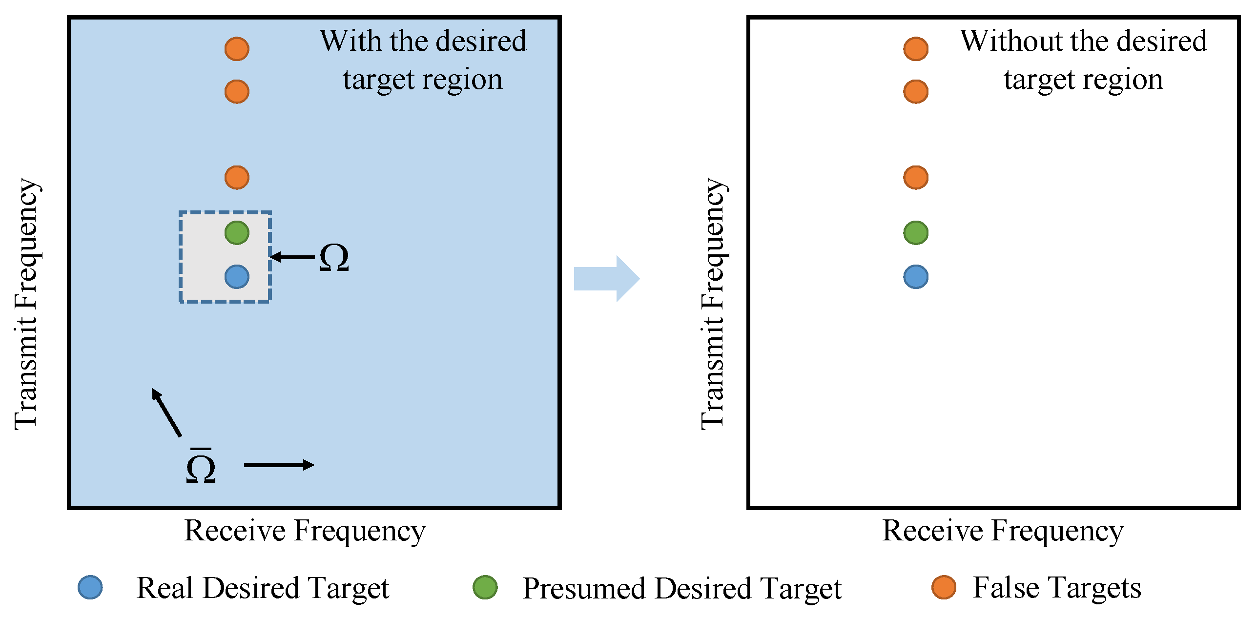
where P [ · ] denotes the acquisition of the principal eigenvectors. However, the reconstruction method proposed above is based on the generalized MUSIC algorithm, which is extremely burdensome in terms of computational effort. Meanwhile, the rough region of the true target in the frequency domain is often difficult to determine, as shown in Figure 3. It will deteriorate the performance of the beamformer under high signal-to-noise ratio (SNR) conditions drastically. Thus, it is necessary to propose a low-complexity covariance reconstruction method that can directly distinguish the true target.

4.2. Matching Capon Reconstruction

The Capon spectrum is a high-resolution spectrum with lower complexity. However, it cannot be applied directly to coherent sources. Thus, by introducing the geometric relationship between the angle of the direct and reflected waves, the relationship between the two received frequencies f r d , f r s can be expressed as
f r s = f 0 d s i n θ s c = f 0 d ( s i n θ d + 2 h a / R ) c f r d
Thus, according to the properties of the Kronecker product, the received signal in Equation (16) can be rewritten as
y = I M N + ρ h e j γ [ I M χ r ( f r d ) ] + ρ h e j γ [ χ t ( f r d ) I N ] + ρ h 2 e j 2 γ [ χ t ( f r d ) χ r ( f r d ) ] [ a t ( f t d ) a r ( f r d ) ] ξ + ρ j I M N + ρ h e j γ [ χ t ( f r d ) χ r ( f r d ) ] [ a t ( f j d ) a r ( f r d ) ] ξ + n G T ( f r d ) A ( f t d , f r d ) ξ + ρ j G J ( f r d ) A ( f j d , f r d ) ξ + n
where ξ = ξ e j 2 π f 0 2 r / c . Two diagonal matrices χ t ( f r d ) , χ r ( f r d ) can be respectively written as
χ t ( f r d ) = d i a g [ 1 , , e x p ( j 2 π ( M 1 ) 2 f r d ) ]
χ r ( f r d ) = d i a g [ 1 , , e x p ( j 2 π ( N 1 ) 2 f r d ) ]
where d i a g [ · ] represents the diagonal matrix with the array elements as diagonal lines. It can be directly observed from Equation (26) that the presence of G T ( f r d ) , G J ( f r d ) prevents the location information of the true and false targets from being accurately represented in the covariance matrix. It means that the Capon spectrum reflecting the targets’ location cannot be obtained directly from the covariance matrix. Fortunately, the receiving frequency f r d of the targets is often available in the scenarios facing range deceptive jamming. Thus, we can construct matrices H T ( f r d ) = G T 1 ( f r d ) , H J ( f r d ) = G J 1 ( f r d ) . The covariance matrices processed by matrices H T ( f r d ) and H J ( f r d ) can be expressed as
R ^ T = A ( f t d , f r d ) A H ( f t d , f r d ) β s 2 + H T ( f r d ) H T ( f r d ) β n 2 + H T ( f r d ) G J ( f r d ) A ( f j d , f r d ) A H ( f j d , f r d ) G J H ( f r d ) H T H ( f r d ) β j 2
R ^ J = A ( f j d , f r d ) A H ( f j d , f r d ) β j 2 + H J ( f r d ) H J ( f r d ) β n 2 + H J ( f r d ) G T ( f r d ) A ( f t d , f r d ) A H ( f t d , f r d ) G T H ( f r d ) H J H ( f r d ) β s 2
where β s 2 , β j 2 , and β n 2 denote the power of the desired signal, jamming, and noise, respectively. It should be noted that the Capon spectrum of the covariance matrices R ^ T and R ^ J reflect only the positions of the true target and the false targets, respectively. Thus, when the approximate region of the true target is not obtained, the reconstruction of the entire frequency domain according to the Capon spectrum of R ^ T is also possible to obtain the accurate steering vector. In addition, the reconstruction covariance matrix based on the matrix R ^ J can directly reject the components of the desired signal. It means that the performance of the beamformer does not degrade under high SNR conditions. Thus, the method processed by the matching matrices H T ( f r d ) and H J ( f r d ) has better robustness. The IPNCM can be expressed as
R ^ i + n = k = 1 K Ω Ω ^ A ( f t , k , f r , k ) A H ( f t , k , f r , k ) A H ( f t , k , f r , k ) ( R ^ J + ζ I M N ) 1 A ( f t , k , f r , k )
where ζ is a tiny number. It avoids the inverse operation when R J is a singular matrix. Similarly, the covariance matrix including desired signal can also be reconstructed as
R ^ s = k = 1 K Ω Ω ^ A ( f t , k , f r , k ) A H ( f t , k , f r , k ) A H ( f t , k , f r , k ) ( R ^ T + ζ I M N ) 1 A ( f t , k , f r , k )
Thus, the estimated steering vector can also be obtained from Equation (24). After the reconstruction of the IPNCM and the estimation of the steering vector, the beamformer in VHF-FDA-MIMO radar can be obtained as
ω = R ^ i + n 1 A ^ ( f t , f r ) A ^ H ( f t , f r ) R ^ i + n 1 A ^ ( f t , f r )
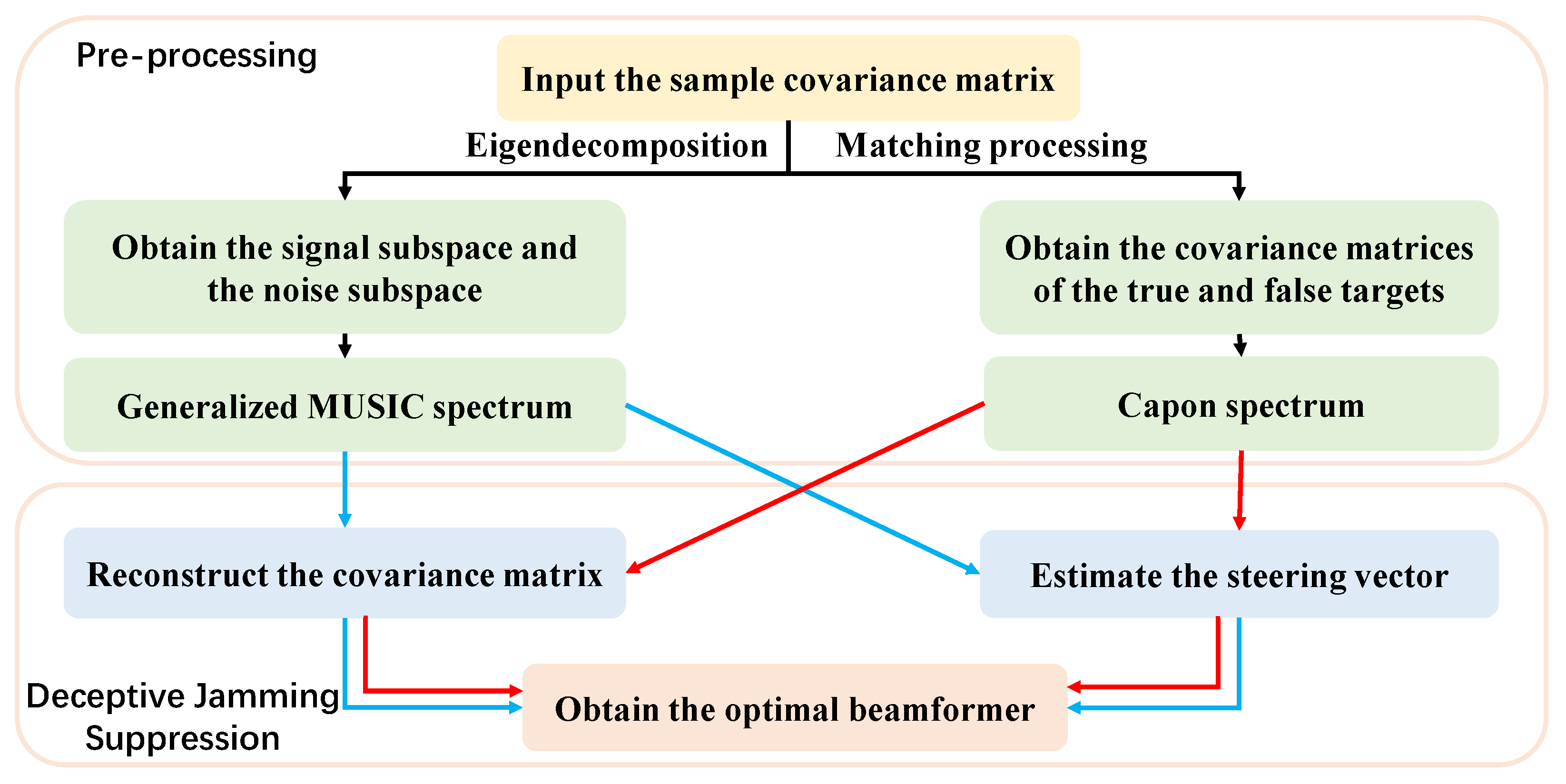
Hence, the steps of the proposed method can be summarized in Figure 4. The computational complexity of the two methods in this paper can be divided into two parts: the reconstruction of IPNCM and the estimation of the steering vector. Thus, the computational complexity of the generalized MUSIC reconstruction (GR) method is O [ ( M N ) 3 + K · [ 64 ( M N ) + 8 3 + 16 ( M N ) + 32 + 8 3 ] ] . The computational complexity of the matching Capon reconstruction (MR) can be calculated by O [ ( M N ) 3 + K · ( M N ) ] . The computational complexity of the steering vector estimation (SVE) is O [ ( M N ) 3 ] .
It should be noted that the two-dimensional covariance reconstruction is unacceptable in terms of complexity. Fortunately, the angle of the target is available to the radar in the face of the mainlobe deceptive jamming, which can be used to reduce the complexity of the method. In addition, the method of dimensionality reduction search for the target energy distribution can be used to reduce the computational effort. However, it is not the focus of this paper, and will not be described here.

5. Simulation

In this section, the deceptive jamming suppression effect under the multipath effect is verified by simulation. The two proposed methods are compared with the unreconstructed method. The main simulation parameters of the VHF-FDA-MIMO radar are listed in Table 1. It should be noted that the 300 MHz carrier frequency corresponds to the 1 m wavelength, which means that this is an FDA-MIMO radar operating at the meter wavelength. The 1 kHz frequency increment provides a degree of freedom in the range domain for MIMO systems.
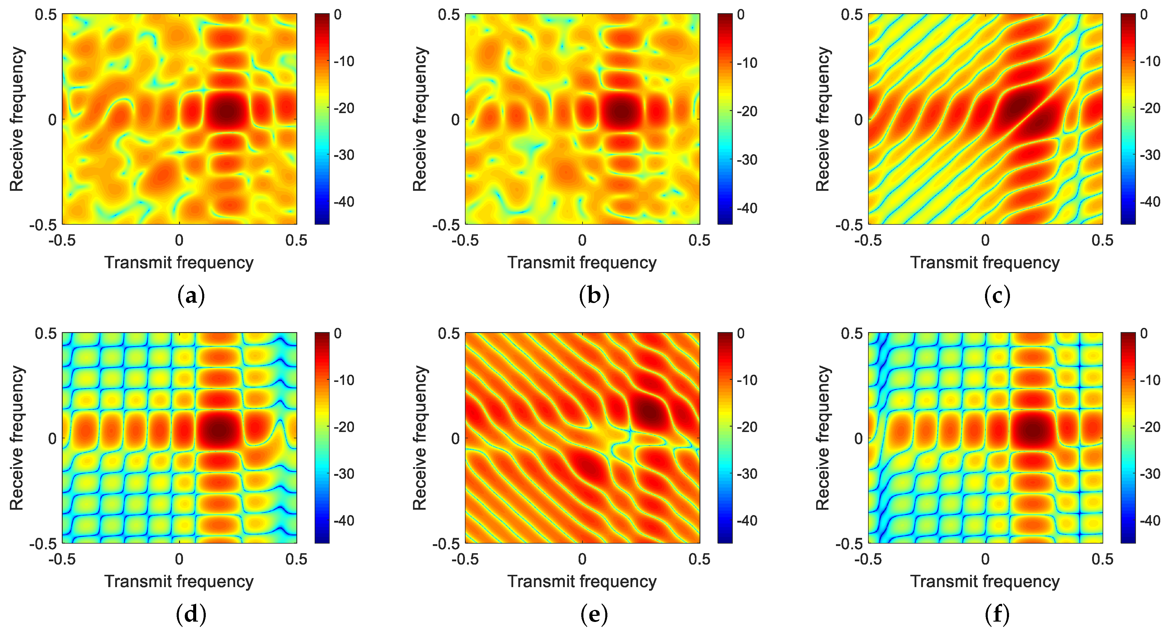
First, the transceive beampatterns of different methods are shown in Figure 5. From Figure 5b, it can be found that when the received covariance matrix is directly used to construct the LSMI beamformer, the beamformer does not have suppression capability for the deceptive jamming, which is due to the signal coherence under the multipath effect. Thus, the method of covariance matrix reconstruction is able to restore the suppression ability of the beamformer on the deceptive target. It can be seen that the beams based on the proposed method are all able to generate null at the location of the false target.
Figure 6 illustrates the transceive beampattern with a signal-to-noise ratio (SNR) of 30 dB in the absence of the desired target region. It can be seen from Figure 6c,e that the beamformer can generate null at the deceptive target location under the high SNR condition. However, the signal of the desired target cannot be removed from the reconstructed covariance matrix due to the lack of a priori information. It means that the signal will be self-canceling, making the performance of the beamformer deteriorate sharply. From Figure 6d,f, it can be found that the reconstructed covariance matrix after matching matrix processing can still directly reject the signal components in the absence of the desired target region. It implies that the matching Capon reconstruction method has better robustness in dealing with deceptive jamming in a multipath environment.
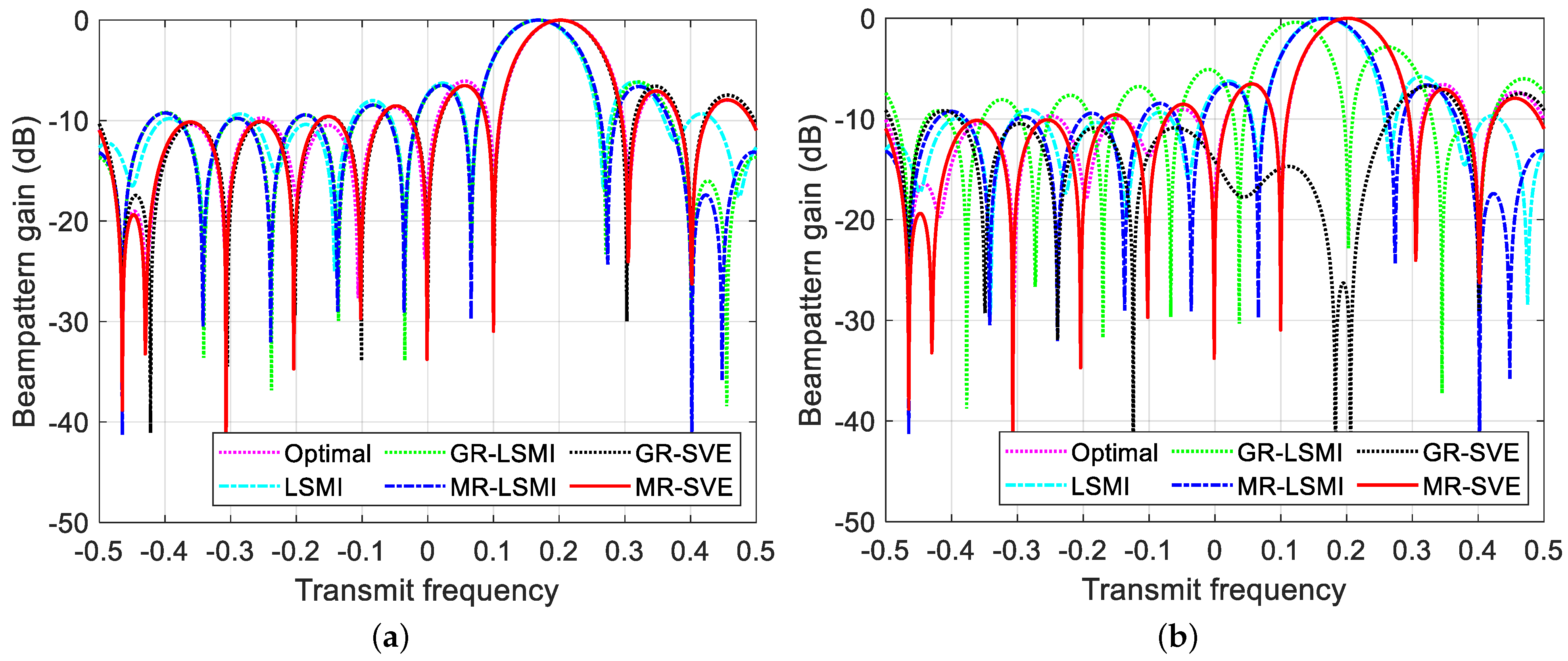
Since the true and false targets are distinguishable in the transmit frequency domain. To visualize more the performance of the beamformer under different a priori conditions, the cross-section of the beampattern in the transmit frequency domain is given. Figure 7a shows the different beampatterns with a SNR of 30 dB when the desired target region is known. In keeping with the above analysis, the beamformer with the direct LSMI method fails to generate null at the false target’s location. There is a significant mismatch in the method of reconstructing only the covariance matrix. The two methods with steering vector estimation processing effectively correct the pointing of the mainlobe. The beampattern cross-section lacking a priori information is given in Figure 7b. A serious self-cancellation phenomenon can be found for the two methods based on the generalized MUSIC reconstruction, which is the result of including the target signal into the covariance matrix together during the reconstruction of the full domain. However, the matching-based method still has excellent mainlobe conformality and interference suppression. The superiority of the method can be fully demonstrated.
Figure 8 shows the performance curves of different methods with the variation of SNR. It can be seen that the conventional LSMI method is ineffective for coherent sources under the multipath effect. Reconstruction-based methods have good interference suppression in all cases when the desired target region is known. The difference in their performance is caused by only a slight difference in reconfiguration accuracy, which implies that the generalized MUSIC reconstruction scheme has some advantages in reconstruction accuracy. However, the generalized MUSIC-based method will fail under high SNR conditions when the prior region of the desired target is lacking. The self-cancellation caused by high input SNR is extremely significant in the MUSIC-based method at this point. In contrast, the method of removing the desired signal with the matching matrix still outputs a stable SINR. Excellent performance is also obtained under high SNR conditions.
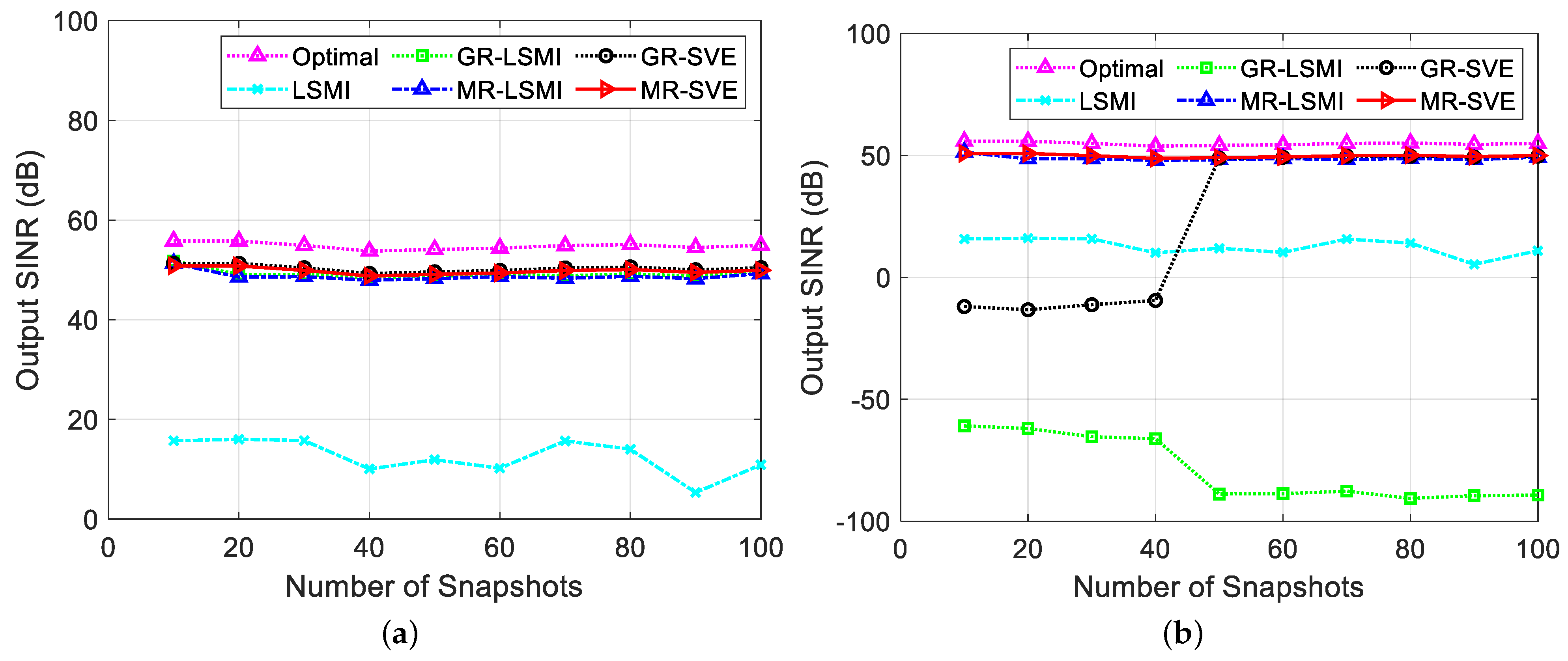
The performance curves of the different methods with the number of snapshots are provided in Figure 9. Unlike the LSMI method that directly processes the covariance matrix, the reconstructed method maintains excellent interference suppression performance even when the desired target region is well known. However, the drawback of the first reconstruction method is shown in Figure 9b. The GR-LSMI method with an arbitrary number of snapshots severely suppresses the desired signal when no information about the target region can be offered. It makes the beampattern completely invalid. After steering vector estimation, the spatial filtering capability of the reconstruction method can be recovered with a high number of snapshots. However, the method with matching Capon reconstructions can maintain good output SINR as the number of snapshots is varied throughout. The method provides significant and remarkable performance improvement under the condition of no prior information and high input SNR.
It is worth pointing out that the proposed method can be used for deceptive jamming suppression of VHF radar in low-elevation scenarios. Thus, accurate parameter estimation and tracking of the true targets can be accomplished. However, the research in this paper mainly focuses on static targets and flat terrain environments. The variable environment in real situations puts demands on the terrain awareness and target awareness capabilities of radar. Thus, the corresponding processing methods are the focus of our future research.

6. Conclusions

In this paper, we derive the signal model of VHF-FDA-MIMO radar facing deceptive jamming under the multipath effect and propose the suppression methods. The signals received under the multipath effect are coherent, and the conventional adaptive beamforming methods cannot be directly used to suppress deceptive targets. Two covariance reconstruction-based methods are used to generate null in the transmit–receive frequency domain where the deceptive target is located. The generalized MUSIC algorithm is implemented to reconstruct the covariance matrix of signal sources. A low-complexity matching Capon reconstruction method is proposed for the self-cancellation phenomenon in the absence of a priori information about the desired target region, which can eliminate the desired signal components by matching matrices. In addition, the idea of reconfiguration is utilized to the estimation of the steering vector. The beampattern and output SINR curves in the simulation results prove the effectiveness of the proposed method, which has a robust suppression capability against deceptive jamming under the multipath effect.

Author Contributions

Conceptualization, Y.L. and J.G.; methodology, Y.L.; software, Y.L.; validation, Y.L., G.C. and J.G.; writing—original draft preparation, Y.L., J.G. and C.W.; writing—review and editing, J.G., G.C., C.W. and M.T.; supervision, C.W. and M.T. All authors have read and agree to the published version of the manuscript.

Funding

This research was funded in part by the China Postdoctoral Science Foundation under grant number 2019M662257, in part by the National Natural Science Foundation of Shaanxi Province under grant number 2021JM-222.

Institutional Review Board Statement

Not applicable.

Informed Consent Statement

Not applicable.

Data Availability Statement

The data used to support the findings of this study are available from the corresponding author upon request.

Conflicts of Interest

The authors declare no conflict of interest.

References

  1. Zheng, G.; Song, Y.; Chen, C. Height measurement with meter wave polarimetric MIMO radar: Signal model and MUSIC-like algorithm. Signal Process. 2022, 190, 108344. [Google Scholar] [CrossRef]
  2. Lo, T.; Litva, J. Low-angle tracking using a multifrequency sampled aperture radar. IEEE Trans. Aerosp. Electron. Syst. 1991, 27, 797–805. [Google Scholar] [CrossRef]
  3. Wu, J.Q.; Zhu, W.; Chen, B. Compressed sensing techniques for altitude estimation in multipath conditions. IEEE Trans. Aerosp. Electron. Syst. 2015, 51, 1891–1900. [Google Scholar] [CrossRef]
  4. Liu, J.; Liu, Z.; Xie, R. Low angle estimation in MIMO radar. Electron. Lett. 2010, 46, 1565–1566. [Google Scholar] [CrossRef]
  5. Wang, S.; Cao, Y.; Su, H.; Wang, Y. Low angle estimation for MIMO radar with arbitrary array structures. Int. J. Electron. Lett. 2019, 7, 422–433. [Google Scholar] [CrossRef]
  6. Tan, J.; Nie, Z. Polarisation smoothing generalised MUSIC algorithm with PSA monostatic MIMO radar for low angle estimation. Electron. Lett. 2018, 54, 527–529. [Google Scholar] [CrossRef]
  7. Liu, Y.; Jiu, B.; Xia, X.G.; Liu, H.; Zhang, L. Height measurement of low-angle target using MIMO radar under multipath interference. IEEE Trans. Aerosp. Electron. Syst. 2017, 54, 808–818. [Google Scholar] [CrossRef]
  8. Liu, Y.; Liu, H.; Xia, X.G.; Zhang, L.; Jiu, B. Projection techniques for altitude estimation over complex multipath condition-based VHF radar. IEEE J. Sel. Top. Appl. Earth Obs. Remote Sens. 2018, 11, 2362–2375. [Google Scholar] [CrossRef]
  9. Xu, Y.; Shi, X.; Xu, J.; Li, P. Range-angle-dependent beamforming of pulsed frequency diverse array. IEEE Trans. Antennas Propag. 2015, 63, 3262–3267. [Google Scholar] [CrossRef]
  10. Khan, W.; Qureshi, I.M. Frequency diverse array radar with time-dependent frequency offset. IEEE Antennas Wirel. Propag. Lett. 2014, 13, 758–761. [Google Scholar] [CrossRef]
  11. Tan, M.; Wang, C.; Li, Z. Correction analysis of frequency diverse array radar about time. IEEE Trans. Antennas Propag. 2020, 69, 834–847. [Google Scholar] [CrossRef]
  12. Xu, J.; Liao, G.; Zhang, Y.; Ji, H.; Huang, L. An adaptive range-angle-Doppler processing approach for FDA-MIMO radar using three-dimensional localization. IEEE J. Sel. Top. Signal Process. 2016, 11, 309–320. [Google Scholar] [CrossRef]
  13. Xiong, J.; Wang, W.Q.; Gao, K. FDA-MIMO radar range–angle estimation: CRLB, MSE, and resolution analysis. IEEE Trans. Aerosp. Electron. Syst. 2017, 54, 284–294. [Google Scholar] [CrossRef]
  14. Xu, J.; Liao, G.; Zhu, S.; Huang, L.; So, H.C. Joint range and angle estimation using MIMO radar with frequency diverse array. IEEE Trans. Signal Process. 2015, 63, 3396–3410. [Google Scholar] [CrossRef]
  15. Xu, J.; Liao, G.; Zhu, S.; So, H.C. Deceptive jamming suppression with frequency diverse MIMO radar. Signal Process. 2015, 113, 9–17. [Google Scholar] [CrossRef]
  16. Xu, J.; Kang, J.; Liao, G.; So, H.C. Mainlobe deceptive jammer suppression with FDA-MIMO radar. In Proceedings of the 2018 IEEE 10th Sensor Array and Multichannel Signal Processing Workshop (SAM), Sheffield, UK, 8–11 July 2018; pp. 504–508. [Google Scholar]
  17. Lan, L.; Liao, G.; Xu, J.; Zhang, Y.; Fioranelli, F. Suppression approach to main-beam deceptive jamming in FDA-MIMO radar using nonhomogeneous sample detection. IEEE Access 2018, 6, 34582–34597. [Google Scholar] [CrossRef]
  18. Lan, L.; Xu, J.; Liao, G.; Zhang, Y.; Fioranelli, F.; So, H.C. Suppression of mainbeam deceptive jammer with FDA-MIMO radar. IEEE Trans. Veh. Technol. 2020, 69, 11584–11598. [Google Scholar] [CrossRef]
  19. Zhang, X.; Cao, D.; Xu, L. Joint polarisation and frequency diversity for deceptive jamming suppression in MIMO radar. IET Radar Sonar Navig. 2019, 13, 263–271. [Google Scholar] [CrossRef]
  20. Xu, J.; Liao, G.; Huang, L.; So, H.C. Robust adaptive beamforming for fast-moving target detection with FDA-STAP radar. IEEE Trans. Signal Process. 2016, 65, 973–984. [Google Scholar] [CrossRef]
  21. Liao, Y.; Tang, H.; Chen, X.; Wang, W.Q.; Xing, M.; Zheng, Z.; Wang, J.; Liu, Q.H. Antenna beampattern with range null control using weighted frequency diverse array. IEEE Access 2020, 8, 50107–50117. [Google Scholar] [CrossRef]
  22. Lan, L.; Liao, G.; Xu, J.; Zhang, Y.; Liao, B. Transceive beamforming with accurate nulling in FDA-MIMO radar for imaging. IEEE Trans. Geosci. Remote Sens. 2020, 58, 4145–4159. [Google Scholar] [CrossRef]
  23. Zheng, G.; Song, Y. Signal model and method for joint angle and range estimation of low-elevation target in meter-wave FDA-MIMO radar. IEEE Commun. Lett. 2021. [Google Scholar] [CrossRef]
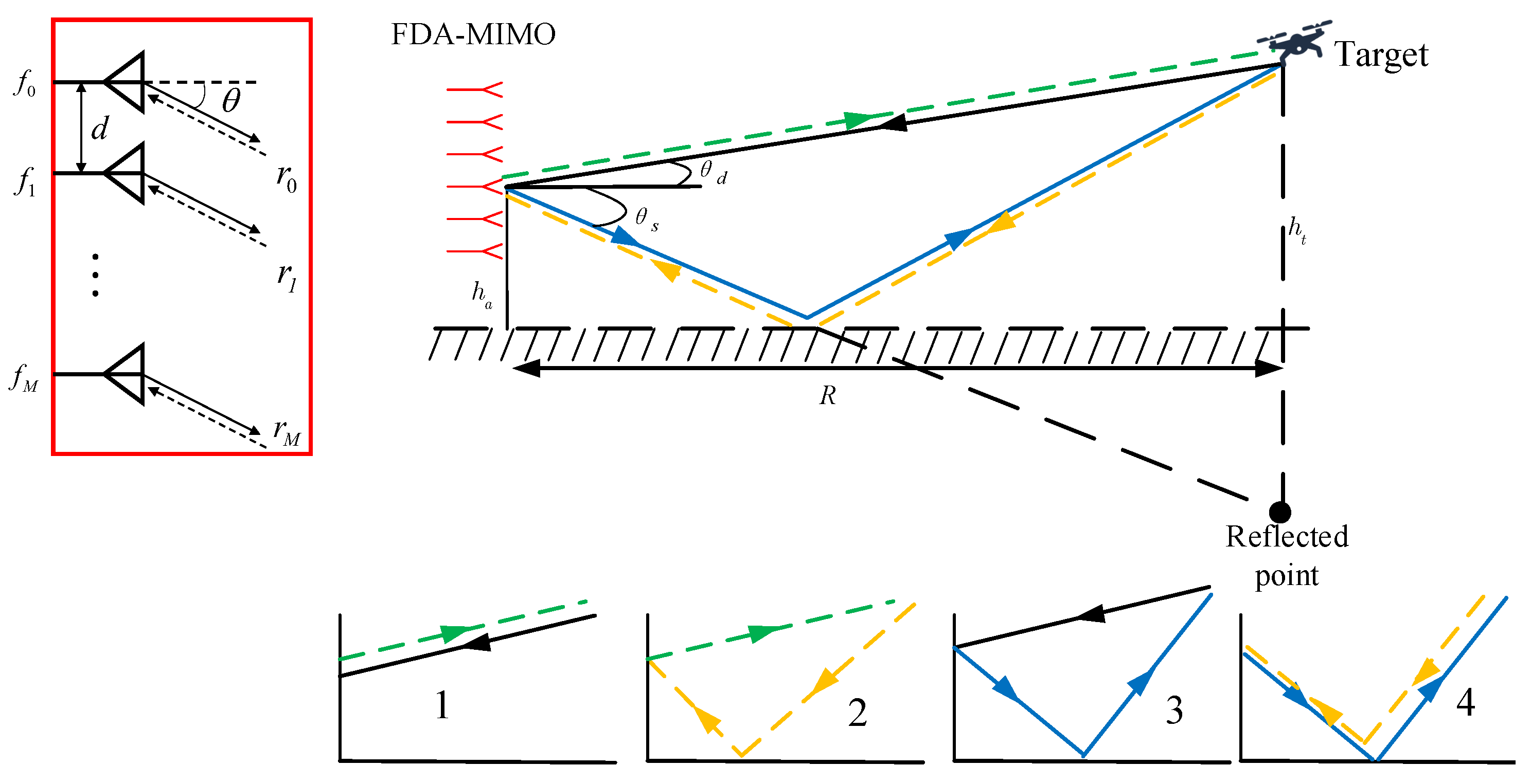
Figure 1. Schematic diagram of reflection model with VHF-FDA-MIMO radar.
Remotesensing 14 00942 g001
Figure 2. Schematic diagram of deceptive jamming model with VHF-FDA-MIMO radar.
Remotesensing 14 00942 g002
Figure 3. Schematic of prior information about desired target region in the transceive domain.
Remotesensing 14 00942 g003
Figure 4. Signal process of the proposed beamformer.
Remotesensing 14 00942 g004
Figure 5. Transceive beampatterns of different method (with the desired target region). (a) Optimal, (b) LSMI, (c) GR-LSMI, (d) MR-LSMI, (e) GR-SVE, and (f) MR-SVE.
Remotesensing 14 00942 g005
Figure 6. Transceive beampatterns of different method (without the desired target region). (a) Optimal, (b) LSMI, (c) GR-LSMI, (d) MR-LSMI, (e) GR-SVE, and (f) MR-SVE.
Remotesensing 14 00942 g006
Figure 7. Cross-sectional view of the beampatterns with different methods. (a) With the desired target region, (b) without the desired target region.
Remotesensing 14 00942 g007
Figure 8. SINR output performance of different methods. (a) With the desired target region, (b) without the desired target region.
Remotesensing 14 00942 g008
Figure 9. Output SINR versus the number of snapshots. (a) With the desired target region, (b) without the desired target region.
Remotesensing 14 00942 g009
Table 1. Simulation parameters for the VHF-FDA-MIMO radar.
ParametersSymbolsValuesParametersSymbolsValues
Size of the array M , N 10INR 30 dB
Carrier frequency f 0 300 MHzTrue target ( r t , θ t ) ( 25 km , 4 )
Frequency increment Δ f 1 kHzFalse target 1 ( r j 1 , θ j 1 ) ( 55 km , 4 )
Array’s height h a 5 mFalse target 2 ( r j 2 , θ j 2 ) ( 75 km , 4 )
Reflection coefficient ρ h 0.9 e j 0.9 π Number of snapshots 10
Publisher’s Note: MDPI stays neutral with regard to jurisdictional claims in published maps and institutional affiliations.