1. Introduction
Passive sensing systems generally use the electromagnetic waves of external radiation source, such as FM broadcast, satellite, digital TV broadcast, etc. It has many advantages, such as anti-stealth, strong survivability, low cost, and not affected by active directional interference; however, the power of the receiver is insufficient for effective target sensing in many cases [
1,
2]. Among many external radiation sources for passive sensing, satellite communication waveforms have high coverage and availability. Thus, target sensing based on satellite communication waveforms has great potential [
3,
4].
Forward scatter radar is a bistatic radar configuration with a special geometry, in which the target is located between the transmitter and the receiver. This means that the bistatic angle is close to 180
[
5]. Compared with conventional radar systems, its main characteristics is scattering. In addition, the radar cross section (RCS) of the target is high in the case of forward scatter [
6]. If the moving target crosses the baseline, it is easier to sense target. This allows the forward scatter radar to use satellites as sources of illumination to sense the target. Meanwhile, although the forward scatter area is very narrow, the richness of the satellite and the convenient handling of the receiver make the satellite forward scatter radar capable of sensing aerial target in a wide area.
Many works have been conducted on forward scatter radar (FSR) [
7,
8,
9,
10]. In particular, there has been progress on the sensing of ground, sea, and aerial targets by the forward scatter radar. For ground target sensing, R. Abdullah et al., constructed a forward scatter system based on the power spectrum difference generated when crossing the baseline [
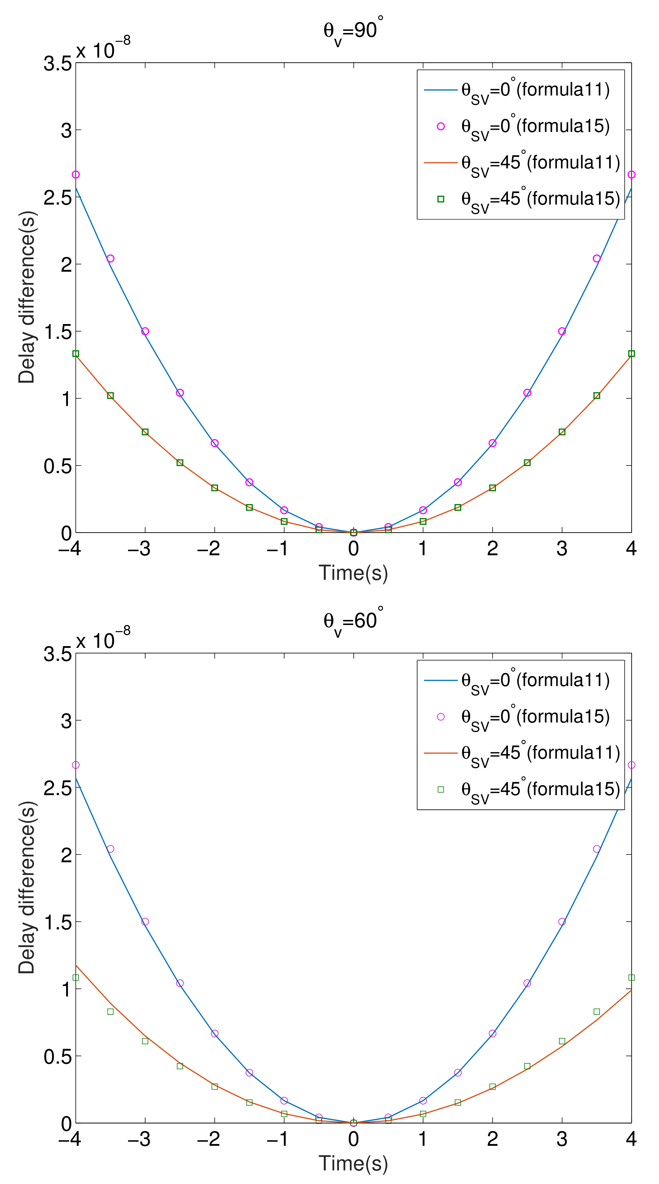
11]. For marine target sensing, transmitters and receivers were set up on both sides of the strait to sense ships that cross the baseline, and echoes with large differences were observed [
12]. References [
13,
14,
15,
16] used machine learning to detect and classify targets, which improved the efficiency of target detection of synthetic aperture radar (SAR). Since the satellite has a low receiving power, and the FSR system has a large radar cross-sectional area, the use of satellites as external radiation sources to construct FSR systems for the aerial target sensing is also one of the important areas of FSR systems. In [
17], the characteristics of the forward-scattered GPS signals were studied when the aircraft crossed the vertical baseline. Numerical results demonstrated that the height of the target crossing the highest point, the azimuth, speed, and other factors from the receiver had considerable impact on the amplitude of the received signals.
The use of satellites as forward scatter radars for passive sensing of aerial targets was studied in [
18,
19]. In [
20], the method for extracting the current signal based on the traditional satellite tracking loop was studied and verified by many field experiments. During the target movement, the FSR signal produces an appropriate Doppler frequency shift [
21]. This work provided a simplified model of the received signal and analyzed its Doppler characteristics in [
22]; however, none of these works has focused on extracting the characteristics from satellite communication waveforms for target sensing; therefore, it is of great significance to study the problem of aerial target sensing in the case of forward scatter.
In this paper, a novel satellite communication waveforms-based aerial target sensing method is proposed, and the main contributions of this paper are as follows:
In order to purify the signal, a zero-notch filter is used to separate the direct wave signal. In addition, the multipath interference is suppressed based on the reversibility of the linear canonical transformation and the suppression effect of Gaussian noise;
The linear canonical transformation is used to process the signal after interference suppression, and the detection statistic is extracted to sense the aerial target;
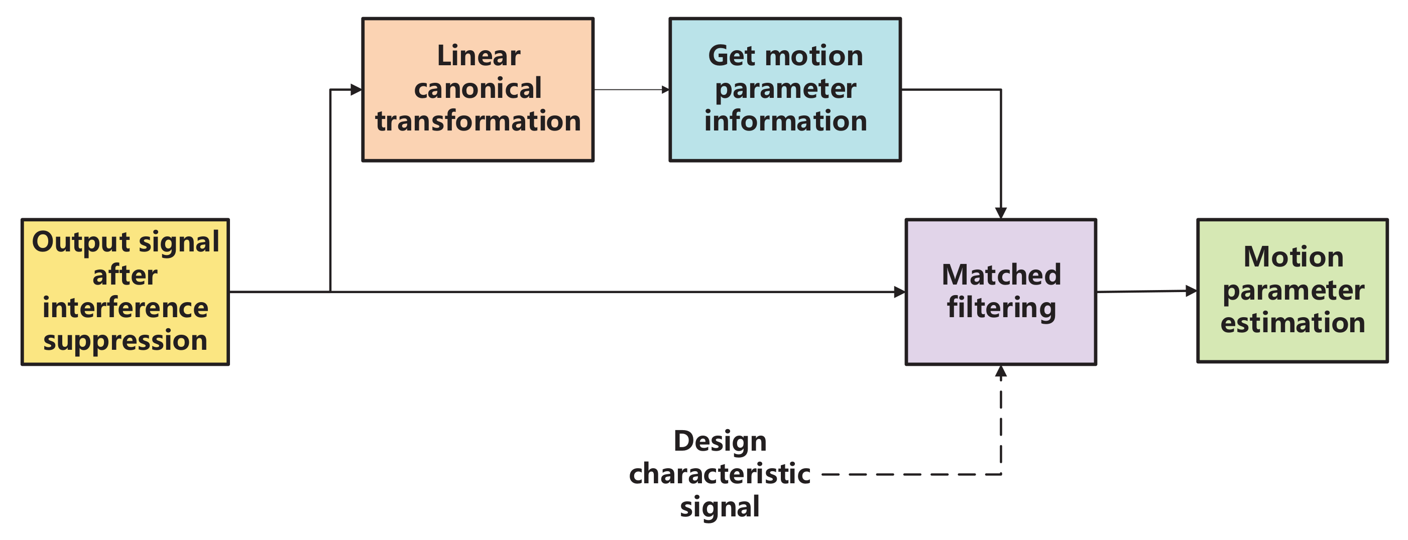
Through the analysis of the forward scatter signal and the characteristics of the linear canonical transformation algorithm, the linear canonical transformation and the matched filter algorithm are combined to estimate the target parameters.
The remainder of this paper is organized as follows. In
Section 2, the system model used in this paper is presented. The suppression of multipath interference is described in
Section 3. Detection statistics and the detector design are proposed in
Section 4. In
Section 5, the performance of target detection is analyzed. Two methods of parameter estimation are proposed in
Section 6. In
Section 7, the performance of parameter estimation is analyzed.
Section 8 shows the numerical results to verify the classification performance. Finally,
Section 9 concludes the paper.
2. System Model
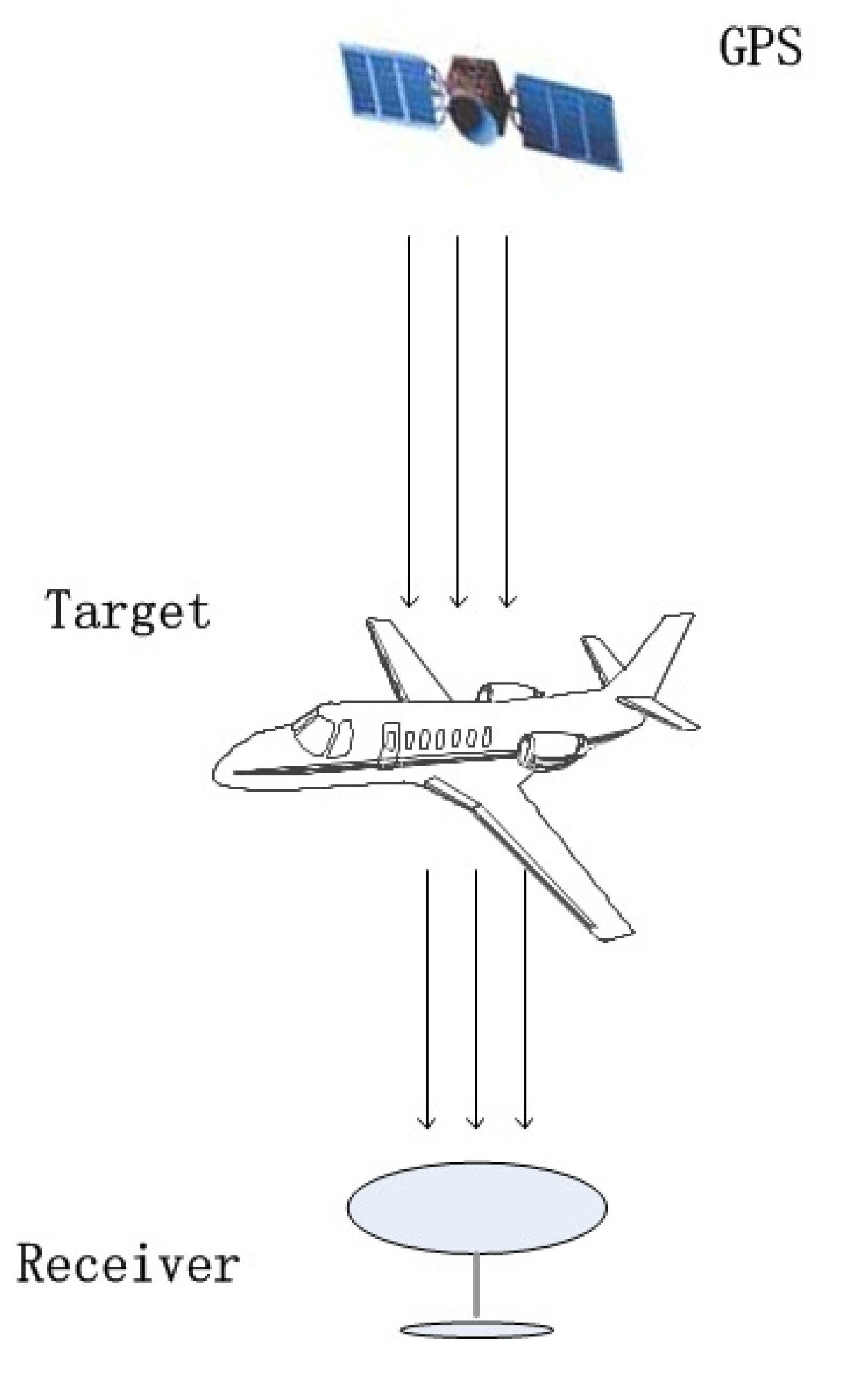
The GPS waveforms-based forward scatter system is shown in
Figure 1. Since the bistatic angle is close to 180
, the signals received by the receiving antenna include direct wave signals, forward scatter signals, multipath interference, and noise. Thus, it requires direct wave suppression and multipath interference suppression for target sensing and target parameter estimation.
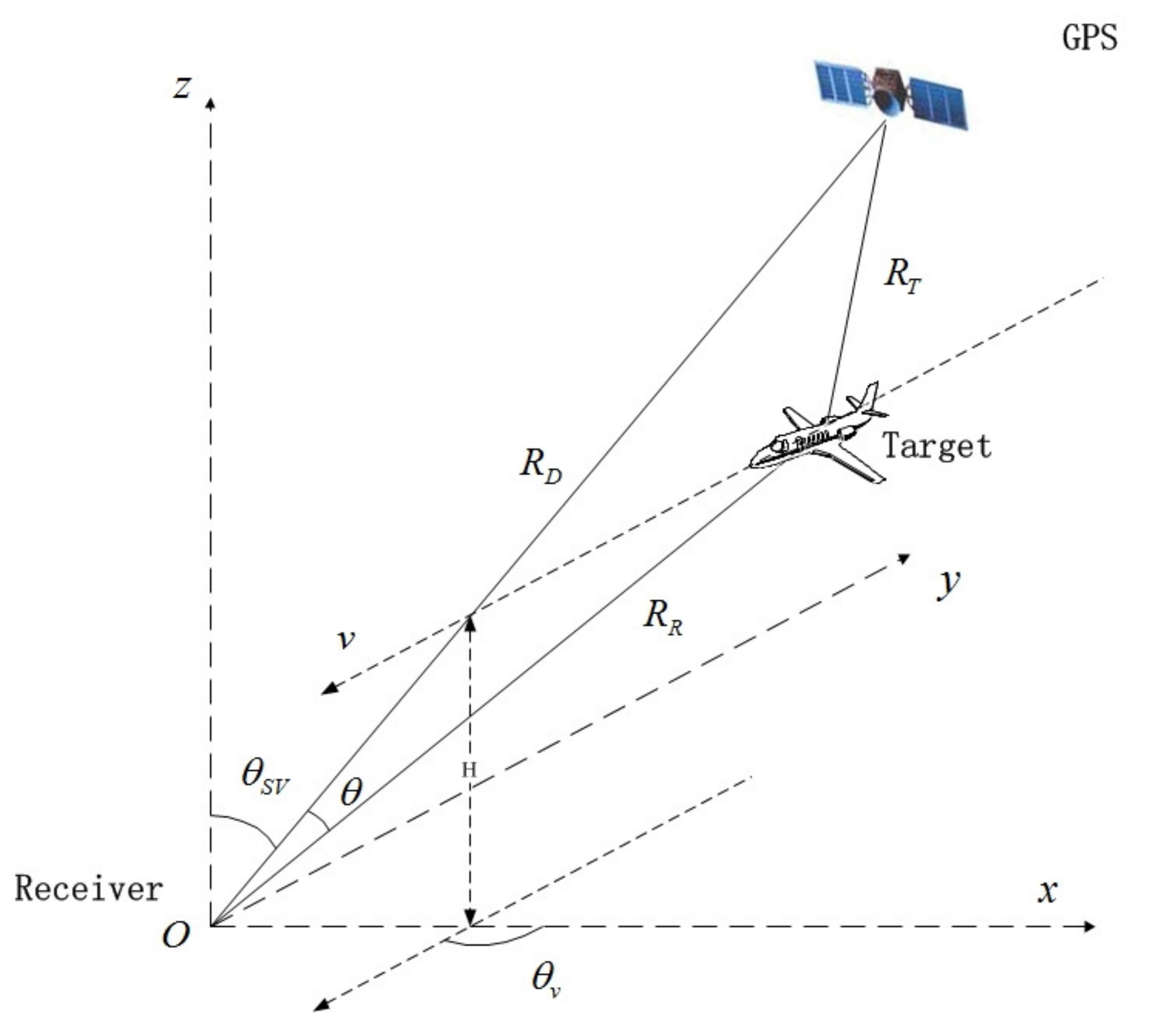
The geometry of the forward scatter system is shown in
Figure 2. In
Figure 2, multipath refers to the propagation of radio signals from the transmitting antenna to the receiving antenna through multiple paths. The scattering of radio waves by the atmosphere, the reflection and refraction of radio waves by the ionosphere, and the reflection of radio waves by surface objects, such as mountains and buildings, will all cause multipath propagation. The system uses GPS as the illuminator, and the receiver is located at the
O point of the coordinate system. It is assumed that the satellite transmitter is located on the
plane, and that the target moves at a speed
v and height
H in a plane parallel to the ground.
denotes the angle between the baseline and the
z axis, and
represents the projection angle between the target trajectory on the ground and the axis. Assuming that the target crosses the baseline, or is near the baseline,
,
,
are the distances from the transmitter to the receiver, from the transmitter to the target, from the receiver to the target, respectively.
represents the angle between
and
.
Compared with conventional radar, the main difference of FSR is its scattering characteristics. In the FSR configuration, the received signal includes the direct wave signal
from the transmitter, the forward scatter signal
due to the presence of the aerial target, the multipath interference and noise; therefore, the signal received by the receiver can be described as
where
denotes the amplitude of the direct wave signal,
represents the amplitude of the forward scatter signal,
is the scatter phase, and
H stands for the order of the multipath channel.
is the amplitude of the direct wave signal after passing through the
jth multipath,
represents the delay of the direct wave signal after passing through the
jth multipath, and
is stationary Gaussian white noise with mean zero.
is the C/A code of the satellite signal and
is the satellite nanvigation data.
denotes the power of the direct wave signal and
represents the power of the forward scatter signal. In addition,
and
indicate delays in the direct and target channels as
where
c denotes the velocity of light.
As the target moves, the scattered signal
exhibits a Doppler change, and its amplitude modulation is specified by the forward scatter mode and the propagation loss. In the forward scatter scenario, it is assumed that the arrival time of the direct wave and forward scatter signal are nearly the same. In this case, there is no distance offset between the two signals, so the effect of the delay difference in the C/A code and the navigation code can be ignored; therefore, the received signal can be rewritten as
Since there is no reference channel for the FSR system, it is necessary to perform preprocessing on the received signal before radar processing. The preprocessing flow chart is shown in
Figure 3 [
23]. In the tracking loop, the code phase and the carrier spectrum are accurately estimated by the code tracking loop and the carrier tracking loop, respectively. I/Q demodulation is often used to realize the tracking loop. According to [
24], code correlation and symbol elimination are performed on the received signal after the down conversion, and the correlation result after signal processing can be obtained as
where
and
are the code correlation gain of the direct wave and target echo, respectively.
stands for the amplitude of the
jth multipath interference, and
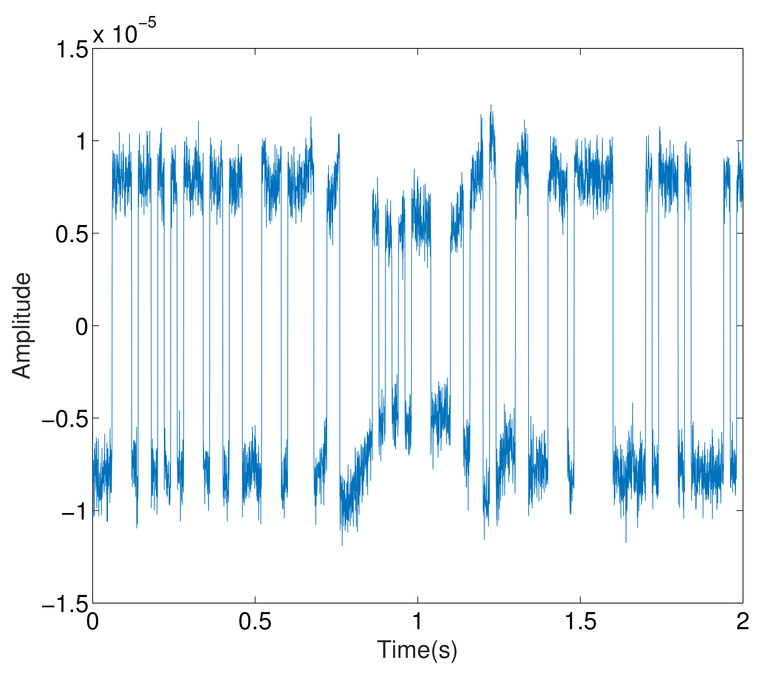
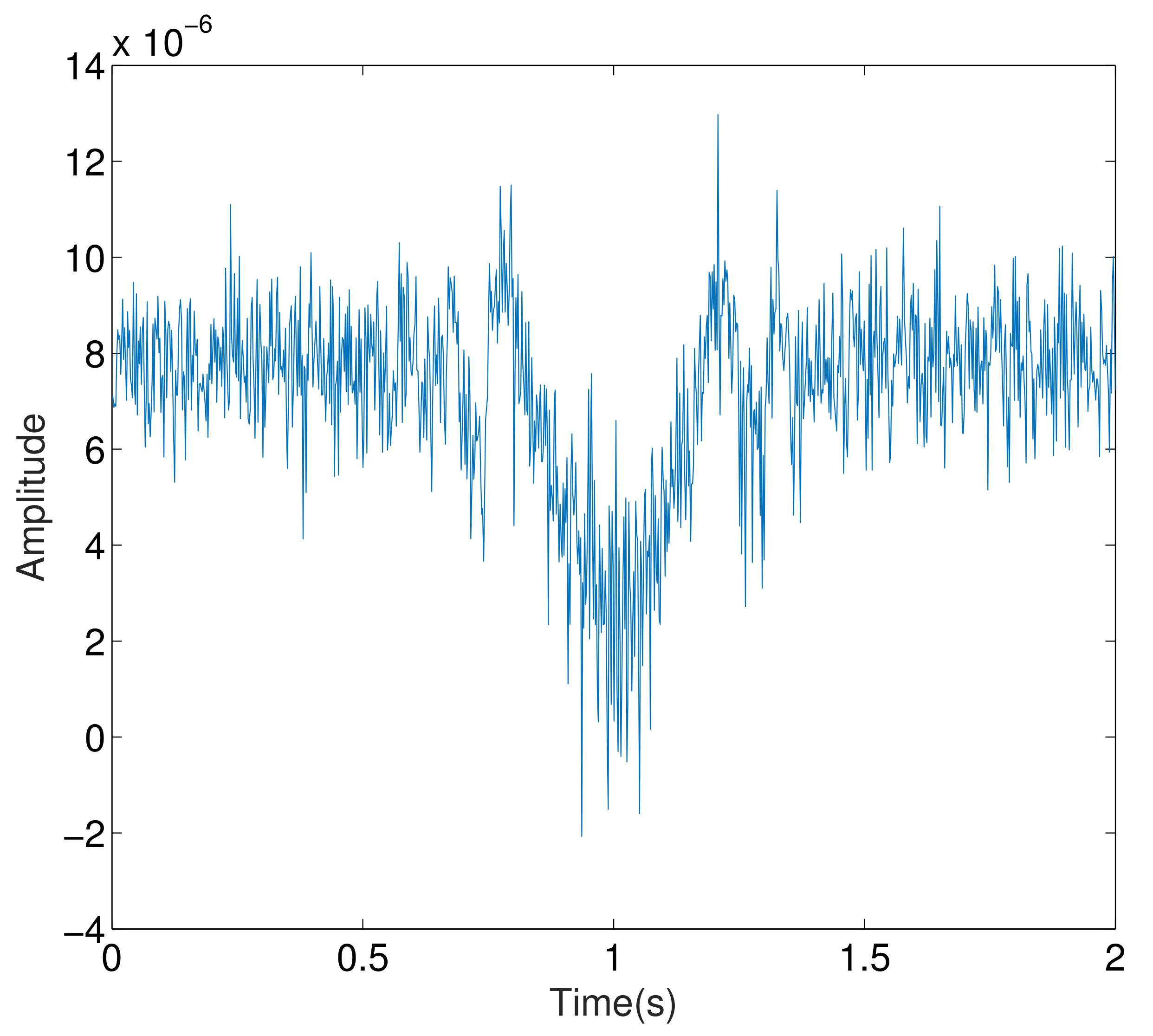
is the Gaussian white noise with mean zero. The output results after processing are shown in
Figure 4 and
Figure 5.
Notch filter refers to a filter that can rapidly attenuate the signal at a certain frequency to remove the signal at this frequency. It belongs to a bandstop filter, and its stopband is very narrow. Due to the target motion, the target echo signal presents Doppler change. In the forward scattering scenario, it can be assumed that the arrival time of direct wave and target echo to the receiver is basically the same, and that there is no distance deviation between the two signals. Then the output of the code correlation processing of the two signals can be considered to be coherent, and the amplitude of the code correlation results can be obtained. According to [
24], since each processing cycle is within a few milliseconds of single-chirp integration time, we can regard the frequency of direct signal and echo signal as constants. For direct signals, this assumption is widely used in traditional navigation satellite signal processing; therefore, the suppression of direct wave signal can be completed by a notch filter. In this case, the received signal can be given by
3. Multipath Interference Suppression
Since the received signal is inevitably affected by the direct wave and multipath interference, the power of the direct wave and multipath interference is higher than the power of the echo signal containing the target. This will affect the sensing. Thus it is necessary to suppress the direct wave and multipath interference.
Linear canonical transform (LCT) is a generalized form of Fourier transform, which has multiple free parameters. Compared with the traditional Fourier transform, it has great flexibility. The traditional method of separating signal and noise is only carried out in either the time domain or the frequency domain, but it is difficult to obtain good filtering and interference separation effect in time domain or frequency domain if there is strong time-frequency coupling between signal components and between signal and noise. In this case, the LCT provides a more suitable filtering and interference separation scheme in another transform domains. For the problem of multipath interference in the receiving channel, using the reversibility of the linear canonical transform and its suppression of Gaussian noise, the Gaussian noise and multipath interference in the channel can be removed by the rectangular window function in its linear regular domain. Thus, the signal after noise suppression is obtained through inverse linear regular transformation. In contrast, Fourier transform can only remove noise and cannot effectively suppress multipath interference; therefore, we choose the linear canonical transform with better filtering and interference separation performance to process the signal.
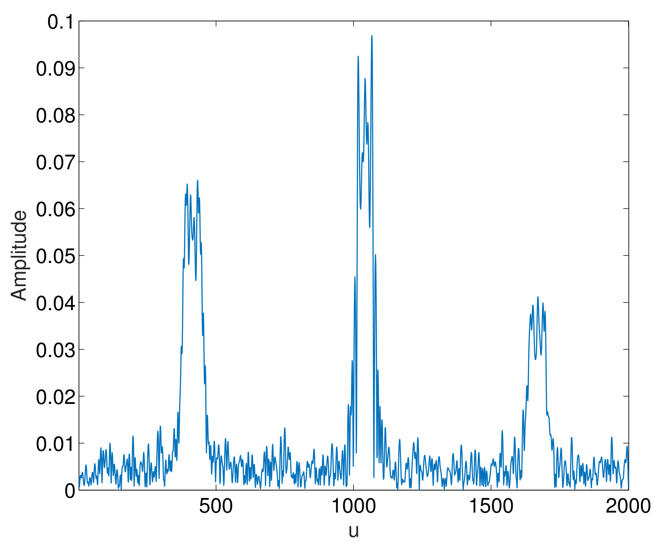
The signal distribution before the multipath interference suppression in the LCT domain is shown in
Figure 6. In
Figure 6,
u represents the LCT domain. Fourier transform and fractional Fourier transform are special forms of LCT, so LCT domain can be regarded as the unity of time domain, frequency domain, and fractional Fourier domain, and contains the information of signal in time domain and frequency domain. Since most of the energy of the echo signal is concentrated in a narrow band centered at the peak point of the linear canonical transform domain, the Gaussian noise does not have good energy concentration in the LCT domain. It can also be seen that the energy distribution of multipath interference is on both sides of the LCT domain; therefore, the peak point can be used as the center of the rectangular window function to filter out the noise and interference.
The steps to design the bandwidth of the rectangular window function are summarized in Algorithm 1.
According to the above analysis, the window function can be constructed to extract the echo signal. The rectangular window function in the linear canonical domain can be expressed as
By applying the reversibility of the LCT algorithm to transform the separated signal, the suppression of direct wave and multipath interference can be achieved. The suppressed signal is subject to LCT again, and the suppression effect is determined by observing whether there is a corresponding peak in the LCT domain. The effect of interference suppression on the signal is shown in
Figure 7. From
Figure 7, we can see that the multipath interference have been well suppressed.
| Algorithm 1 Rectangular window function bandwidth design |
- 1:
Perform LCT on the signal to obtain the LC spectrum of the signal ; - 2:
Perform least squares polynomial fitting to obtain a smooth power spectrum curve; - 3:
Derivative the smoothness power spectrum curve, and extract the positions of the maximum and minimum points of the slope derivative value near the center point of the LC domain from a and b, respectively. Further, use the difference as the bandwidth estimation; - 4:
Design the number of cycles and repeat the above operation to obtain the statistical average.
|
8. Numerical Results and Discussion
In order to evaluate the performance of the proposed method, the GPS satellite communication waveforms are used. The sensing performance is determined by [
30,
31]
where
represents the detection accuracy,
and
N are the numbers of correct detections and the total number of detections, respectively.
In the simulation, we adopt the GSM TU 6 channel model. Using this multipath fading model, the following experiments examine the performance of the proposed algorithm for target echo signal detection.
In order to evaluate the influence of sampling points on the sensing performance, the parameters are set as follows: the sampling frequency is MHz, the false alarm probability is , the GPS direct wave power is dBm, the symbol rate is MHz, the carrier frequency is GHz, the aerial target altitude is 10 km, the flight speed is 100 m/s, the average power of the echo signal is dBm; 2000 Monte Carlo simulations are used.
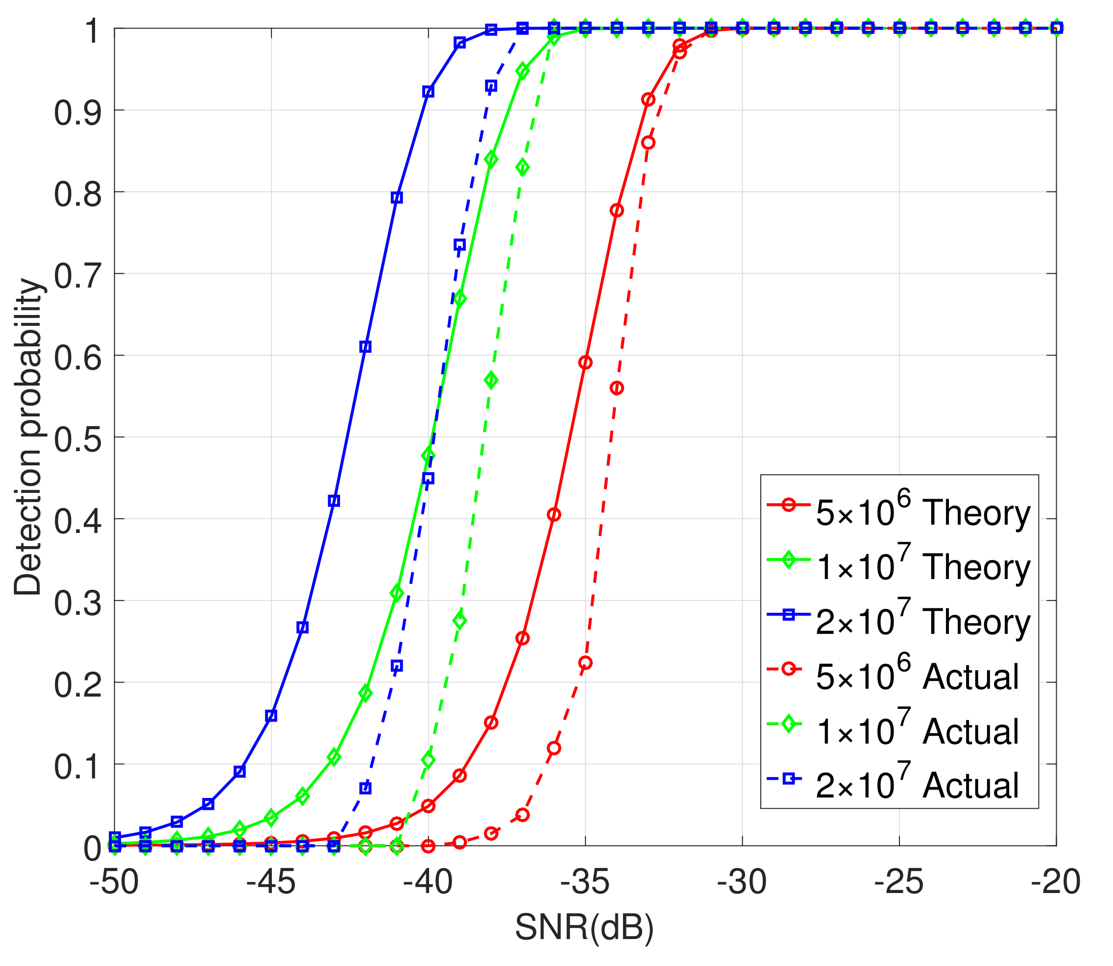
It can be seen from
Figure 12 that the target sensing performance improves as the number of sampling points increases. This is because the increase in the number of sampling points will increase the cumulative number of points in the time domain, resulting in the enhancement of the peak height in the corresponding LCT domain, thus improving the sensing performance. Although the number of sampling points is an important factor, the limited sensing range in the case of forward scatter prevents sampling points from increasing indefinitely, and the sampling points should be set reasonably. When the number of sampling points is
, the sensing performance reaches
with SNR = −31 dB. When the number of sampling points is
, the sensing performance can reach
with SNR = −36 dB, and when the number of sampling points is
, the sensing performance can reach
with SNR = −37 dB. At the same time, it can be seen that under the same number of sampling points, as the signal-to-noise ratio increases, the detection effect is better. The actual simulation performance is basically consistent with the theoretical derivation, which verifies the effectiveness of the proposed method.
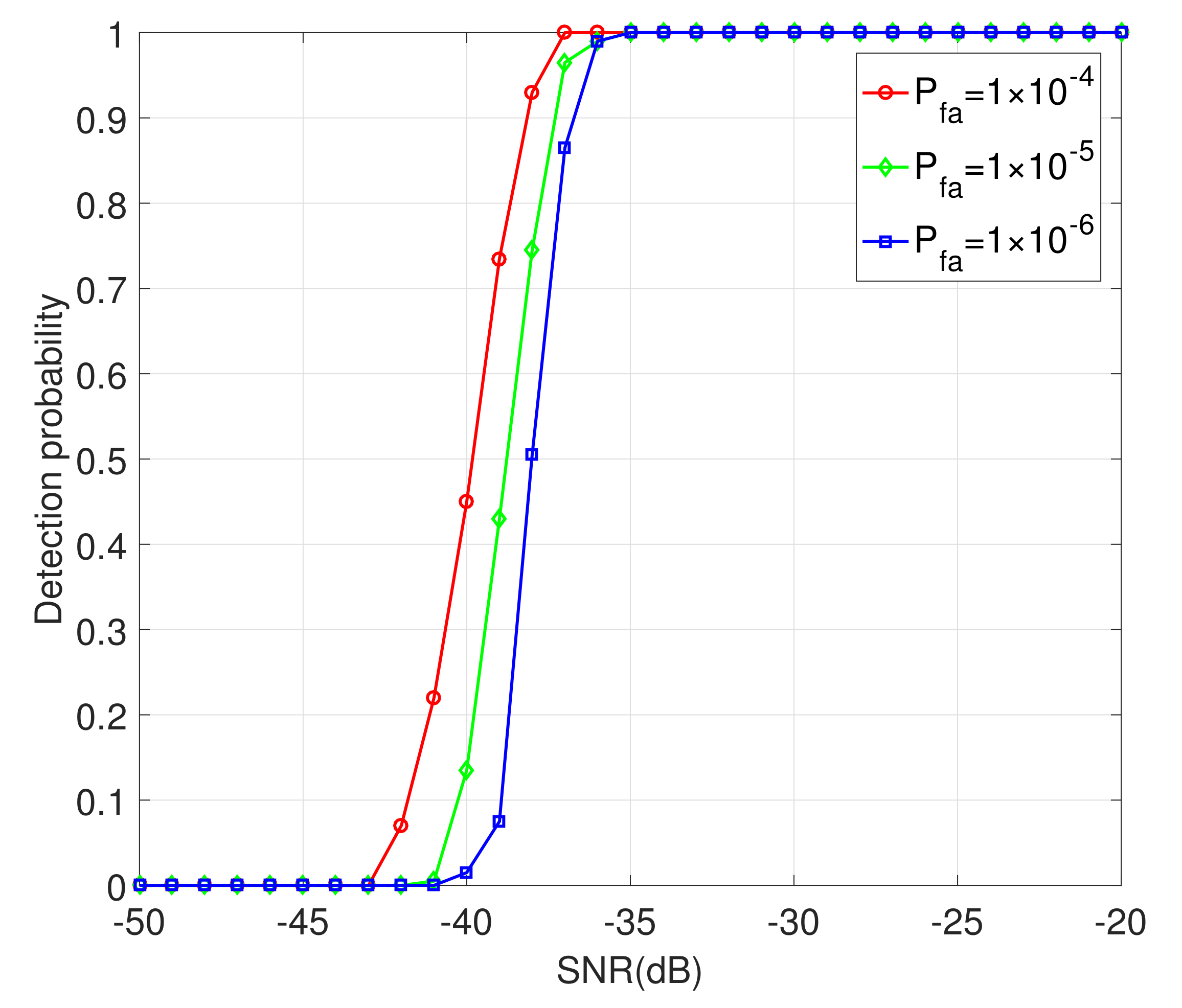
In order to evaluate the target sensing performance of forward scatter echo signal for different false alarm probabilities, the parameters are set as follows: the sampling frequency is MHz, the sampling points is , the GPS direct wave power is dBm, the symbol rate is MHz, the carrier frequency is GHz, the aerial target flight altitude is 10 km, the flight speed is 100 m/s, the average power of the echo signal is dBm; 2000 Monte Carlo simulation results are used.
It can be seen in
Figure 13 that, as the false alarm probability increases, so does the target sensing performance under the same conditions. When the false alarm probability is
, the sensing performance can reach
with SNR = −37 dB, and when the false alarm probability is
, the sensing performance under SNR = −35 dB can reach
, and when the false alarm probability is
, the sensing performance can reach
with SNR = −34 dB.
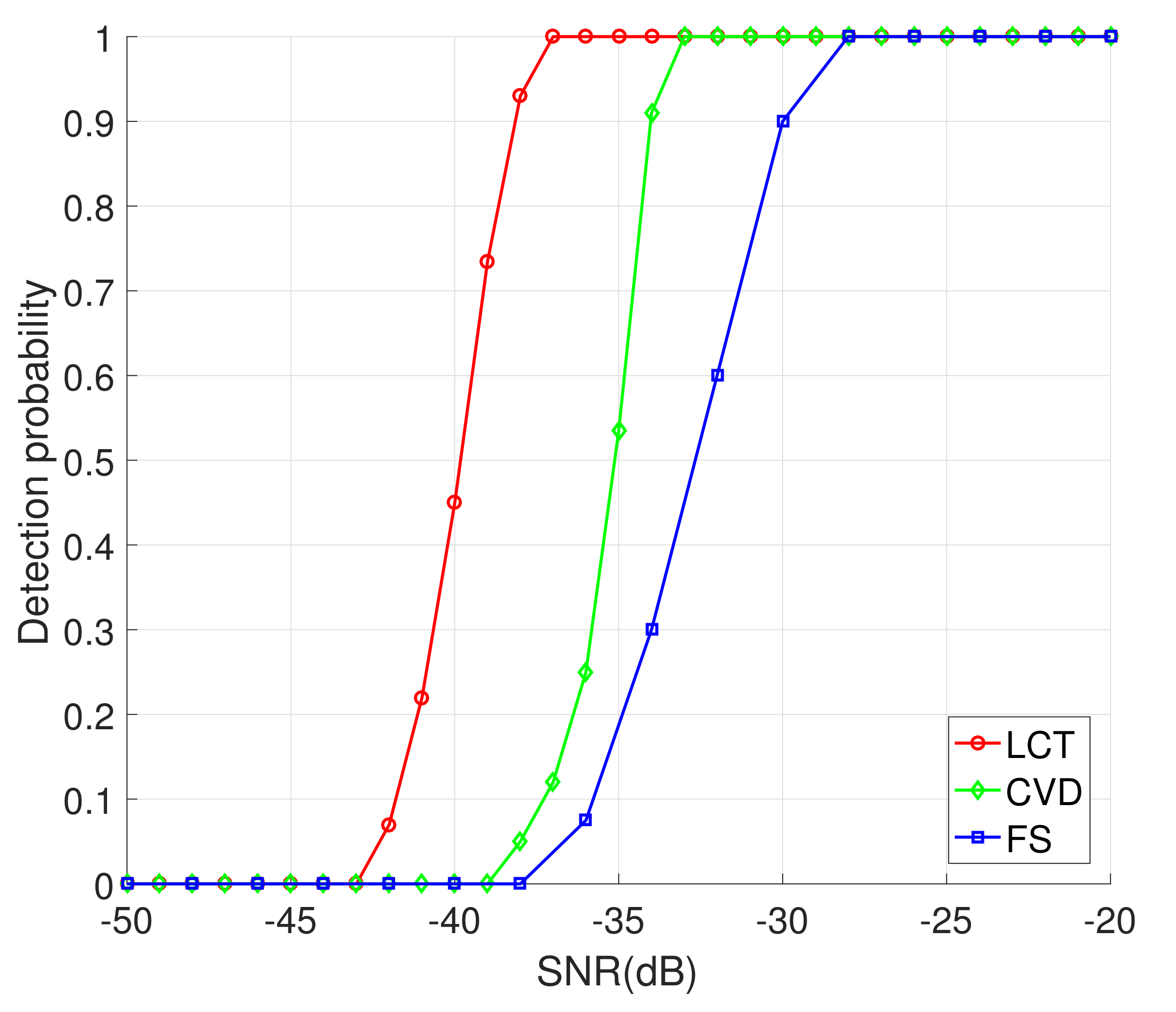
Next, we compare the target sensing performance of the proposed method with these of [
32,
33]. The parameters are set as follows: the sampling frequency is
MHz, the sampling points is
, the false alarm probability is
, the GPS direct wave power is
dBm, the symbol rate is
MHz, the carrier frequency is
GHz, the aerial target flight altitude is 10 km, the flight speed is 100 m/s, the average power of the echo signal is
dBm; 2000 Monte Carlo simulations are used.
As can be seen from
Figure 14, the sensing performance of the proposed method is better than [
32,
33]. This is because the proposed method based on LCT has a good interference suppression effect; therefore, under the same conditions, the detection amount of the proposed method is more conducive to the detection of target echoes, which is superior to the method proposed in [
32]. The method proposed in [
33] is based on the shadow area in the case of forward scattering, but as the height of the target increases, its attenuation at the baseline decreases, which is not conducive to target detection. The computational complexity of the proposed method is
, and the computational complexity of [
32] method is
, and the computational complexity of [
33] method is
, where
N denotes the number of signal sampling points,
M stands for the number of sampling points in the linear canonical domain, and
and
m are the number of searches. Overall, although the computational complexity of the proposed method is higher than [
32,
33], the proposed method has better target sensing performance and multipath interference suppression effect.
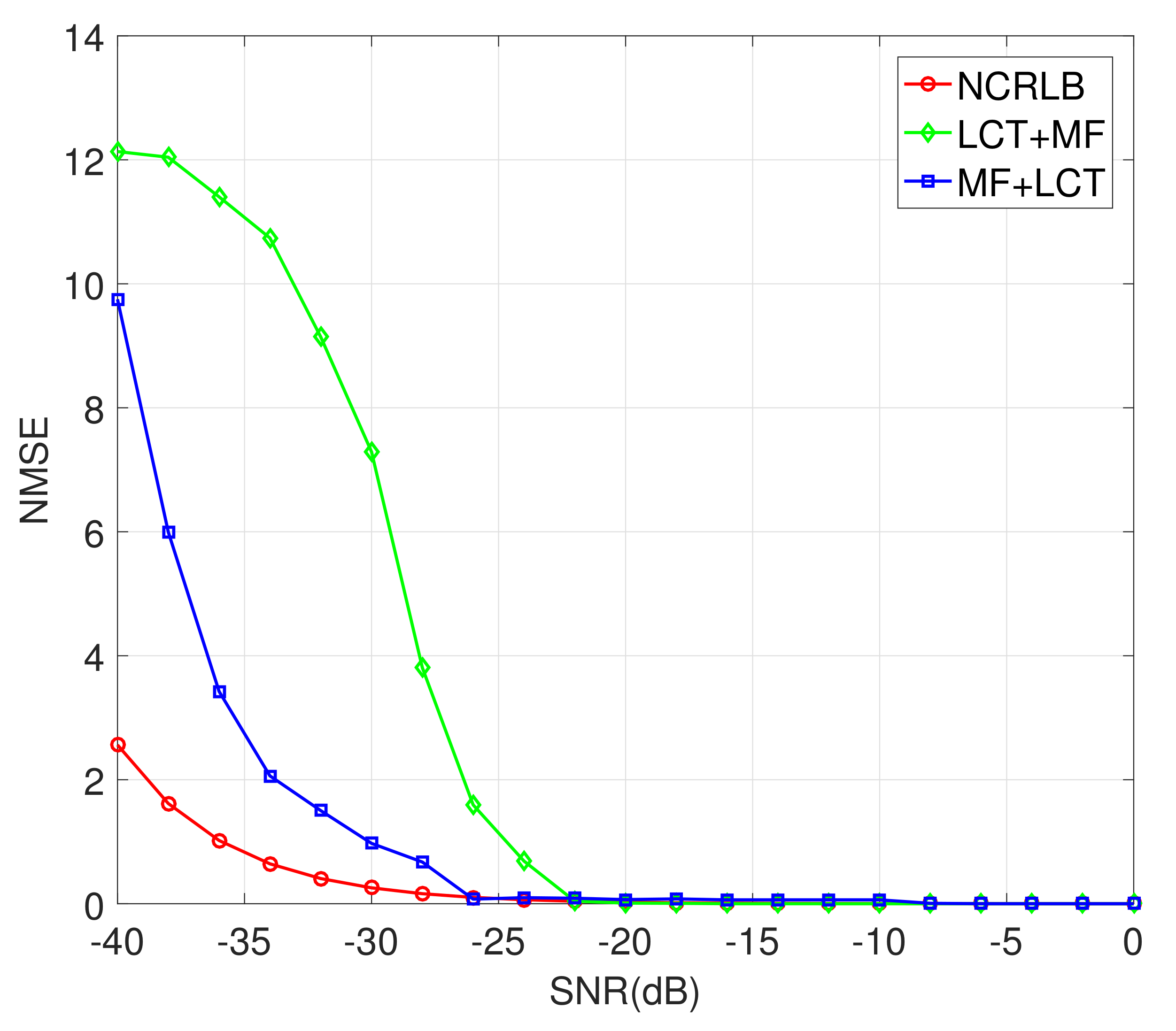
In order to evaluate the target parameter estimation performance of the proposed method, the parameters are set as follows: the sampling frequency is MHz, the sampling points is , the GPS direct wave power is dBm, the symbol rate is MHz, the carrier frequency is GHz, the target flight altitude is 8 km, the flight speed is 125 m/s, the average power of the echo signal is dBm; 2000 Monte Carlo simulation results are used.
As can be seen from
Figure 15, both the proposed LCT+MF method and the proposed MF+LCT method in this paper can achieve good estimation performance for the target flight altitude, and they improve as the signal-to-noise ratio (SNR) increases. This is because the increase in the SNR makes the corresponding peaks during parameter estimation more prominent, thereby improving the parameter estimation performance. The normalized minimum mean square error of the height estimation achieved by the LCT+MF method reaches
when SNR = −17 dB and the estimation performance of the MF+LCT method reaches
when SNR = −21 dB. From the above, the proposed methods have good estimation performance, which shows that the aerial target parameter estimation methods have good interference suppression effect.
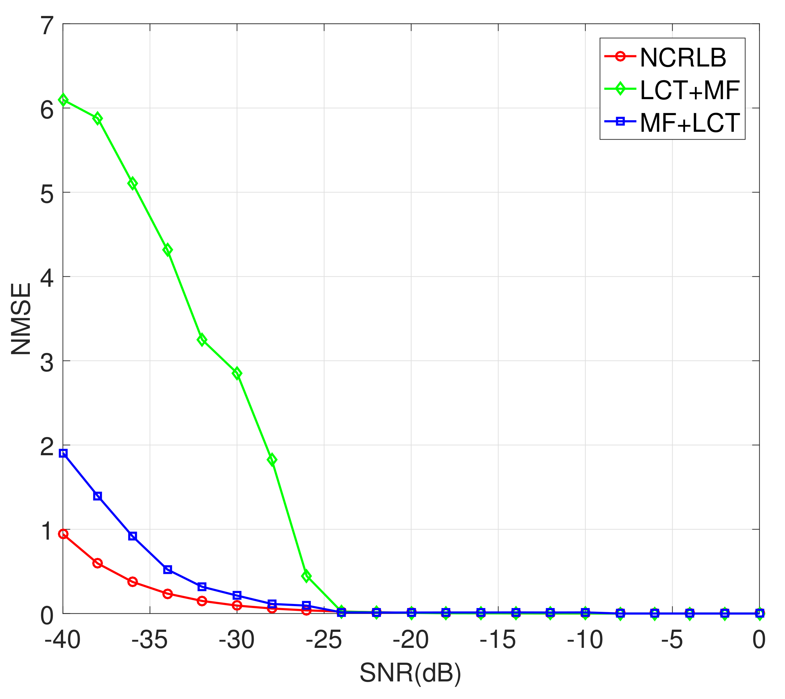
From
Figure 16, both the proposed LCT+MF method and the proposed MF+LCT method in this paper can achieve the good estimation performance of the target flight speed, and estimation performance improves as SNR increases. When SNR = −19 dB, the LCT+MF method and MF+LCT method can reach
, and the MF+LCT method is better than LCT+MF in the case of low SNR. These results show that the LCT algorithm has a good suppression effect on interference.
To compare the parameter estimation performance of the proposed method with [
34], the parameters are set as follows: the sampling frequency is
MHz, the sampling points is
, the GPS direct wave power is
dBm, the symbol rate is
MHz, the carrier frequency is
GHz, the target flight altitude is 8 km, the flight speed is 125 m/s, the average power of the echo signal is
dBm; 2000 Monte Carlo simulation results are used.
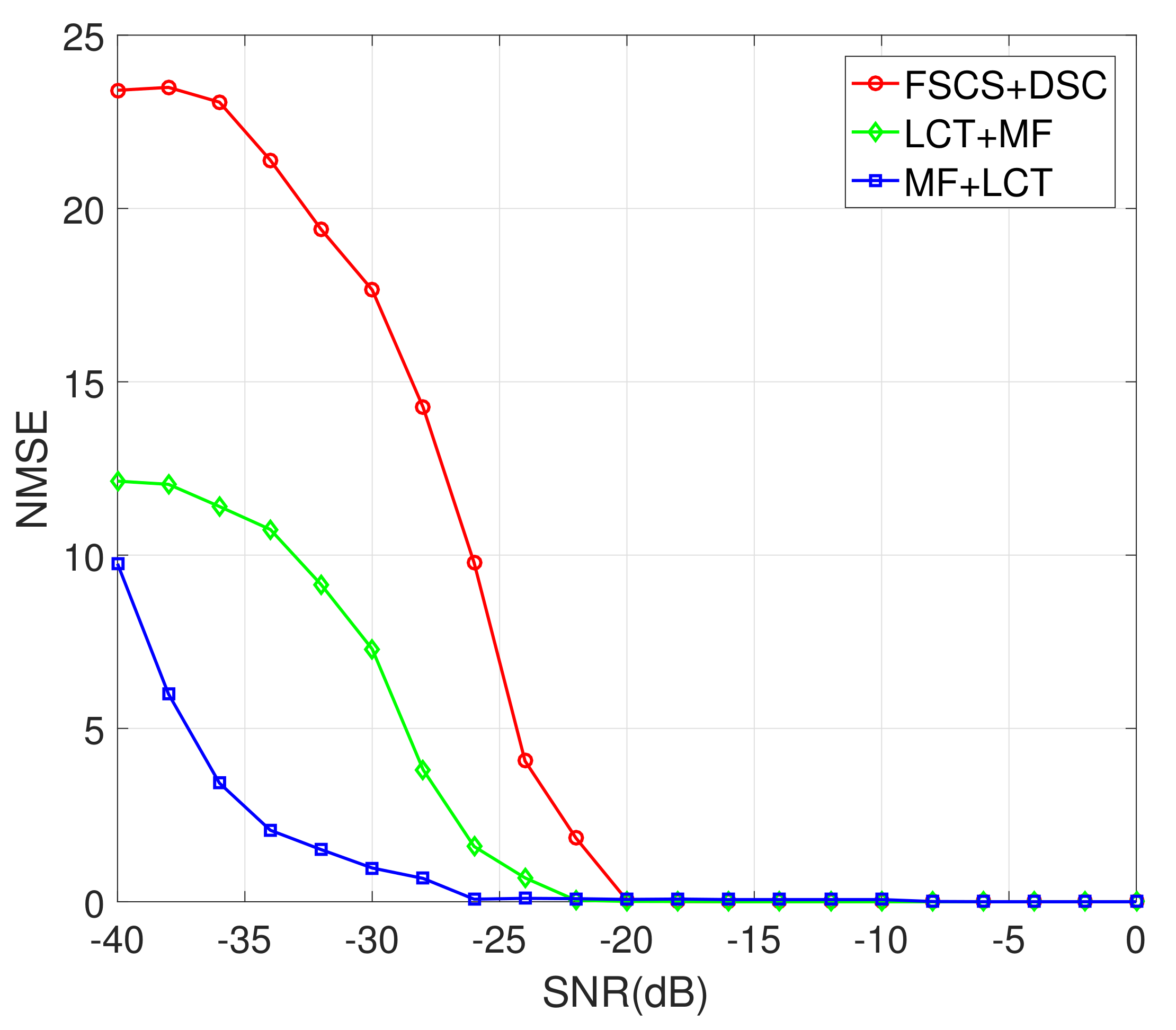
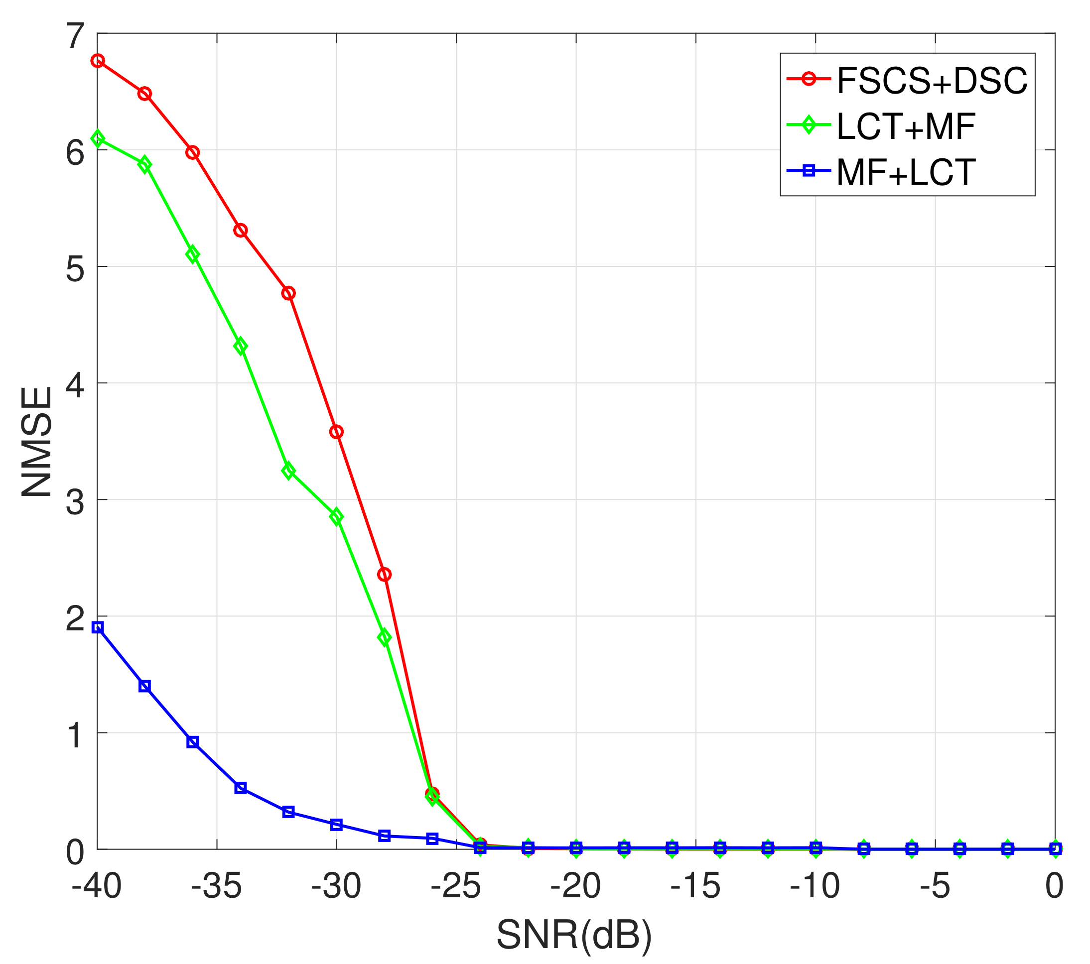
It can be seen from
Figure 17 and
Figure 18 that the proposed method is better than [
34]. This is because the proposed method completes the estimation of the target motion parameters based on the LCT based on the analysis of the forward scattered signal. The MF+LCT method and LCT+MF adopt the noise suppression effect of LCT and the time delay characteristics of the forward scattered signal, thus the proposed method has better estimation performance at low SNR. The computational complexity of the two methods are
and
, respectively, and the computational complexity of [
34] is
, where
n is the total number of searches for speed and altitude. From the above, although the computational complexity of the proposed methods is higher than [
34], the proposed method can achieve better target parameter estimation performance.
