Article

Detection of Surface Crevasses over Antarctic Ice Shelves Using SAR Imagery and Deep Learning Method

1
Key Laboratory of Digital Earth Science, Aerospace Information Research Institute, Chinese Academy of Sciences, Beijing 100094, China
2
University of Chinese Academy of Sciences, Beijing 100049, China
*
Author to whom correspondence should be addressed.
Remote Sens. 2022, 14(3), 487; https://doi.org/10.3390/rs14030487
Submission received: 31 December 2021 / Revised: 16 January 2022 / Accepted: 18 January 2022 / Published: 20 January 2022
(This article belongs to the Special Issue The Cryosphere Observations Based on Using Remote Sensing Techniques)

Abstract

:
Crevasses are formed by glacier movement and the stresses within glacier ice. Knowledge of the crevasses’ distribution is critical for understanding the glacier and ice shelf stability. In this study, we propose an automated crevasse extraction framework based on Sentinel-1 SAR imagery and an improved U-Net network. The spatial distribution of crevasses on Antarctic ice shelves in 2020 was mapped with a spatial resolution of ~40 m, and the characteristics of crevasses on the Nickerson Ice Shelf, Jelbart Ice Shelf, Amery Ice Shelf, Thwaites Glacier, and Shackleton Ice Shelf were analyzed. The results indicated the extraction accuracy of our method was 84.2% and the F1 score was 72.5%. Compared with previous published studies, the identification of the crevasse areas had good visual consistency. However, in some scenes, the recall rate was relatively lower due to the quality of the SAR image, terrain surrounding the crevasses, and observation geometry. The crevasses on different ice shelves had different characteristics in terms of length, density, type, and spatial pattern, implying the different stress structures of ice shelves. The Thwaites Glacier and the Nickerson Ice Shelf in the West Antarctica Ice Sheet (WAIS) had shorter ice crevasses, whereas the lengths of ice crevasses on the Jelbart Ice Shelf and the Amery Ice Shelf in the East Antarctica Ice Sheet (EAIS) were relatively long. Nevertheless, there are more closely spaced crevasses on the ice shelf in WAIS compared to that in the EAIS. For the distribution of crevasse types, the Nickerson Ice Shelf and the Shackleton Ice Shelf had various forms of crevasses. There were mainly transverse crevasses developed on the Jelbart Ice Shelf and the Amery Ice Shelf. This study provides a helpful reference and guidance for automated crevasse extraction. The method proposed by this study manifests great application potential and the efficacy of producing a time-series crevasse data set with higher spatial resolution and larger coverage. In the future, more Sentinel-1 SAR imagery will be applied and the effect of temporal and spatial variations in crevasses on the stability of ice shelves will be investigated, which will contribute to project the ice shelf stability and explore the sea level rise implications of recent and future cryosphere changes.

1. Introduction

Crevasses have developed on almost all glaciers and ice shelves and are the direct result of glacier movement, reflecting the characteristics of glacier development and stresses [1,2]. The crevasses contribute to the glacier mass balance through impacting the processes of meltwater transportation on the ice surface [3,4,5]. Additionally, when sufficient surface meltwater infuses into crevasses, hydrofracturing may be induced, resulting in ice shelf instability; thus, crevasses are essential factors for assessing the stability of glaciers and ice shelves [6]. Antarctic scientific research expeditions are also closely associated with crevasses because the rapid appearance of crevasses may herald the disintegration of the ice shelf and pose a serious safety hazard to field researchers [7,8]. The orientation and distribution of crevasses can be used to distinguish the ice flow regimes and provide qualitative insight into trends in ice flow [9]. Therefore, crevasses are critical not only for investigating the ice shelves’ stability as well as glacier dynamics but also for providing important safety guidance for glaciological field campaigns.
The earliest method used to detect ice crevasses was radar, mainly ground-penetrating radar (GPR), which has been used in Antarctica since 1975 [10,11]. As an on-site detection method, ground-penetrating radar has high positioning accuracy and can realize accurate detection of ice crevasses. This detection method is more dependent on the operator’s experience and signal detection in heavily crevassed environments. Furthermore, it is dangerous when the operator is disturbed by external conditions or is fatigued and slows down in response [12]. With the need for investigations and the development of radar detection systems, airborne radar systems have also been used in Antarctic scientific expeditions. At present, remote sensing is an important means to identify ice crevasses [13]. Many satellite images, including Landsat images in low and medium resolution [14], high-resolution SPOT images [15], MODIS images [6,16], Worldview Panchromatic images [17], and high-quality aerial images [18,19] are used to detect and extract glacier surface features such as ice crevasses in a great deal of current research. In addition, satellite laser altimeter systems [13] and LIDAR altimetry [20,21,22] are usually used to detect the ice crevasses.
At present, most of the ice crevasse detection methods based on remote sensing images are visual interpretation [4] or threshold segmentation [23], which are limited to a small scale. Although these methods can obtain better performance, they require a lot of professional knowledge and operator time, because it is difficult to quickly map crevasses continent-wide. With the rise of artificial intelligence algorithms, machine learning has been widely used in cryosphere studies [24,25]. Methods combining geostatistics and neural network deep learning have also been applied to the extraction of ice crevasses [6]. Williams et al. [12] developed an ice crevasse detection technology based on the Hidden Markov-Support Vector Machine (HMM-SVM). In addition, the Deep Convolutional Neural Network was selected as the machine learning model to identify fracture with better performance than other sets of models, and the outputs were used to evaluate the vulnerability of Antarctica’s ice shelves [6].
However, there are some limitations on the previous research on crevasse identification. In terms of data sources: (1) The application of ground-penetrating radar for field detection has a high cost and low efficiency, and there are great risks and safety hazards in the ice crevasse fields, making it unsuitable for large-scale ice crevasse detection. (2) Optical remote sensing images are susceptible to weather and extreme climates, and there are certain limitations in detecting ice crevasses in the Arctic and Antarctic regions. In contrast, Spaceborne synthetic aperture radar (SAR) cannot be affected by weather conditions and can obtain clear images with a long time sequence and a wide range [26]. On the other hand, the SAR system is very sensitive to the surface roughness of ground objects and can penetrate the snow cover layer several meters deep to detect buried ice crevasses that cannot be detected by optical sensors. In terms of detection technology: (1) The method of visual interpretation is greatly influenced by a person’s subjectivity, and the workload is relatively large, so it cannot be applied to the identification of large-scale crevasses. (2) Machine learning methods based on support vector machines and random forests are more complicated in design. Different technical routes need to be designed for different regions. The efficiency of large-scale promotion of ice crevasse detection is low, and the accuracy of the results needs further examination.
Therefore, we propose an automated framework based on an improved U-Net network and Sentinel-1 SAR data for ice crevasse detection. Because of the penetration advantage of SAR, Sentinel-1 cannot be affected by cloudy weather in Antarctica, providing sufficient data resources for ice crevasse detection. At the same time, a higher resolution can achieve a finer crevasse detection effect. It even penetrates the thin snow cover of the ground surface and detects crevasses that cannot be identified by optical images. The deep learning model based on the U-Net network can realize automatic ice crevasse detection through small sample training. It also provides technical support for the detection of large-scale ice crevasses.
The remainder of this paper is structured as follows. Section 2 describes the study area and data set. Section 3 introduces the methodology, including data processing and the improved U-Net architecture, and Section 4 performs accuracy assessment on the ice crevasse detection results and analyzes the spatial distribution pattern and feature of ice crevasses on five ice shelves in the Antarctic region. Following this, Section 5 further discusses the credibility of the crevasse detection results. Finally, Section 6 summarizes the conclusions of the study.

2. Study Area and Data Set

2.1. Study Area

The Antarctic ice sheet is the largest ice sheet in the world and comprises an ice mass equivalent to 58 m of global sea level rise [27]. Broadly, the Antarctic ice sheet is divided into the Antarctic Peninsula (AP), the Eastern Antarctic Ice Sheet (EAIS) and the Western Antarctic Ice Sheet (WAIS). EAIS and WAIS are bounded by trans-Antarctic Mountain belt [28]. In this study, we focused on five classical glaciers and ice shelves: Jelbart Ice Shelf, Thwaites Glacier, Nickerson Ice Shelf, Amery Ice Shelf, and Shackleton Ice Shelf (Figure 1).
The Jelbart Ice Shelf is located on the edge of Dronning Maud Land in eastern Antarctica. It covers an area of 11,000 km2 and is fed by Schytt Glacier [29]. The surface of this ice shelf has a large number of relatively regular striped features, and similar surface structures can also be seen on other ice shelves, such as the Fimbul Ice Shelf [30] and Larsen C Ice Shelf [31]. Thwaites Glacier, located on the Walgreens coast of Marybird Land in West Antarctica, is very wide and flows continuously and quickly into Pine Island Bay in the Amundsen Sea. Thwaites Glacier is one of the fastest melting glaciers in Antarctica, so it has earned the title of “Doomsday Glacier”. The Nickerson Ice Shelf has the warm Amundsen Sea to the east and the cold Ross Sea to the west. Previous simulation studies have shown that among all the ice shelves in Antarctica, the ice shelf in the Amundsen Sea is expected to undergo tremendous changes in the next few decades from the warming of sea water. If the ice shelf collapses, it will affect the flow of inland ice to the ocean, along with the process and the stability of the entire ice sheet. The Amery Ice Shelf is located in the lower reaches of the Lambert Glacier basin in East Antarctica. It is the largest ice shelf in East Antarctica and the third largest ice shelf in Antarctica, covering an area of about 1.4 × 10⁶ km2. The ice stream is discharged through a narrow exit about 200 km from the front edge of the ice shelf. The ice current system is highly active and extremely sensitive to global climate and sea level changes. It is one of the most active areas of glacier movement in the Antarctic ice sheet. The Shackleton Ice Shelf is located at 90°E to 105°E, covering 33,820 km2 of eastern Antarctica and enclosing 384 km of coast. As the northernmost ice shelf in eastern Antarctica, close to the continental shelf, Northcliffe, Denman, and Scott Glaciers all flow into the sea through the Shackleton Ice Shelf. The study areas are evenly distributed on the Antarctic continent (Figure 1) and are areas where ice crevasses are known to exist.

2.2. Sentinel-1 SAR Data

The synthetic aperture radar data used in this study came from the Sentinel-1 satellite. The Sentinel-1 satellite is an earth observation satellite in the European Space Agency’s Copernicus Project (GMES). It is composed of two satellites, Sentinel-1A and Sentinel-1B, an observation constellation. The shortest revisit period after the double star operation is 6 days, and images can be continuously provided day and night. The Sentinel-1 satellite is equipped with a C-band synthetic aperture radar. The center wavelength of the C-band is about 5 cm, which can penetrate the snow cover and obtain the ice surface information under it [32]. The data have an ultra-high radiometric resolution of 1 dB (3σ) and radiometric stability of 0.5 dB (3σ), which can effectively improve the accuracy of radar image parameter inversion. The revisit frequency and coverage of Sentinel-1 are significantly better than ERS-1 and ERS-2 and Envisat satellites.
The Sentinel-1 SAR data used in this study came from the European Space Agency and were freely available (https://scihub.copernicus.eu/dhus/#/home, accessed: 15 January 2022), providing two orbit directions: ascending and descending; four operating modes: Interferometric Wide Swath (IW), Wave (WV), Strip map (SM), Extra Wide Swath (EW); four polarized data: HH, HV, VV, VH; and three formats: GRD, SLC, RAW. In Antarctica, only the EW mode, HH single-polarization-type Sentinel-1 data can be used unconditionally. EW is a wide-format mode, which is more in line with the application goals in the Antarctic area than other modes. HH polarization image is the most suitable for balancing the overall power of the image and the contrast between crevasses and non-crevasses. GRD (Ground Range Detected) data refer to ground range multi-view images, with small data volume and high data processing efficiency. In accordance with the characteristics of the research object in this study, the EW mode and HH polarized GRD data were used. The range resolution of the image was 20 m, the azimuth resolution 40 m, and the width 410 km.
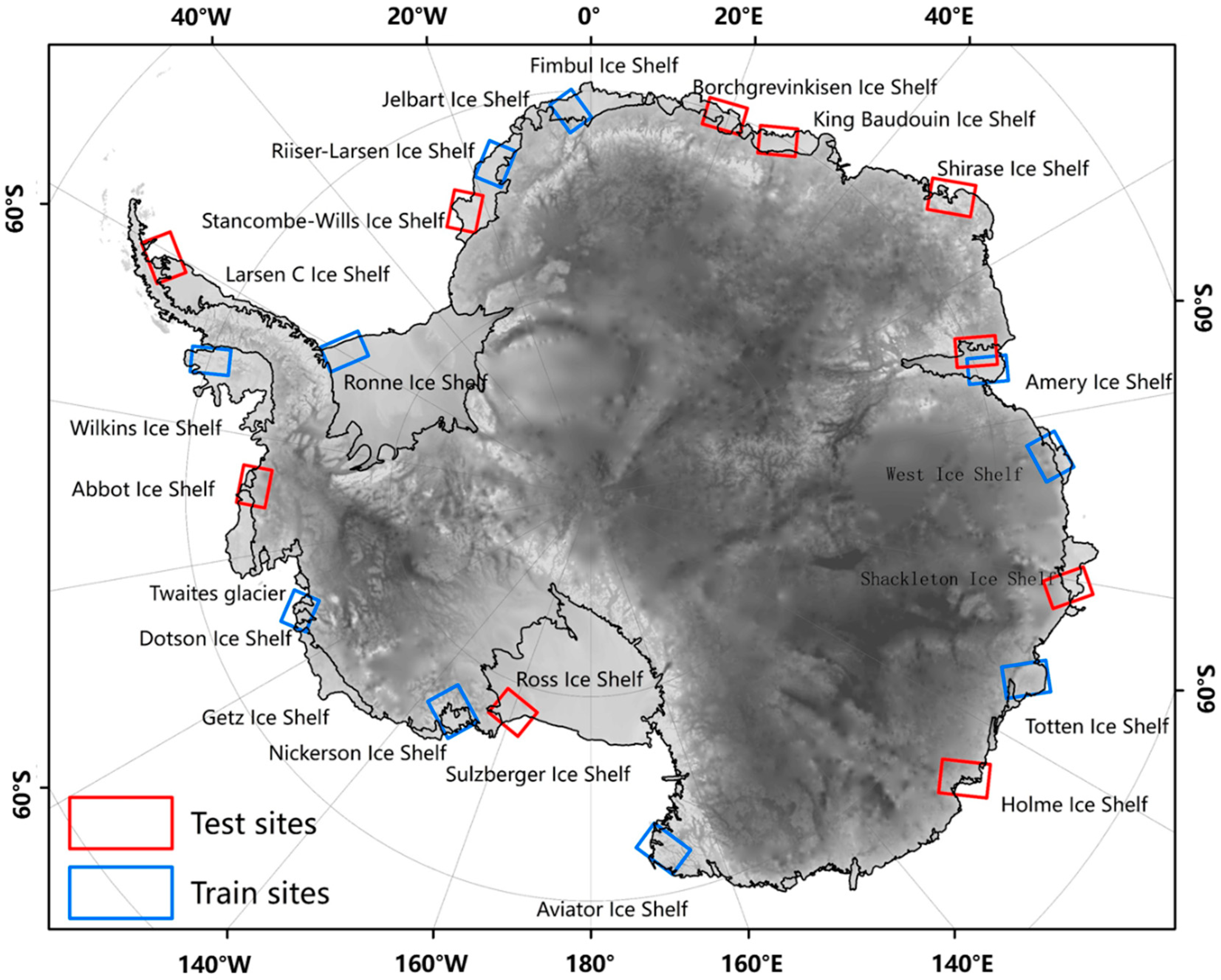
Figure 2 shows the spatial distribution of the training and test sites, which were evenly distributed on the Antarctic continent. Table 1 provides information on the SAR data used for training and testing implemented in this study. The training sites included one region on the AP, two regions in the WAIS, and seven regions in the EAIS. In order to test the practicality of the algorithm, the testing sites included ice crevasses with different characteristics and crevasses that were difficult to distinguish from the single-polarization Sentinel-1 data. In total, 10 of the independent test sites were used, including one region of the API, two regions on the WAIS, and seven regions on the EAIS. The training and test sites were almost evenly spaced. In order to ensure the representativeness of the sample, the training data should cover different forms of ice crevasses. Therefore, we selected different time phases of ascending and descending orbit data sources and marked different ice shelves and different types of ice crevasses.

2.3. Auxiliary Data

In order to eliminate the misclassification of ice crevasses in the post-processing process, the Antarctic ice shelf data were used for mask trimming. The Antarctic ice shelf vector layer is a summary of the ice shelves derived from the Antarctic mosaic from 2013 to 2014. It does not include seasonal (winter) ice that extends farther across the continent. The source of data was from Natural Earth (https://www.naturalearthdata.com/, accessed: 15 January 2022). In order to describe the distribution of ice crevasses and other characteristics, we also performed processing operations such as attribute editing and area calculation for the Antarctic ice shelf data.
In order to distinguish regions of likely crevasses, we overlay the ice flow velocity data. The source of the Antarctic ice shelf velocity data is MEaSUREs Annual Antarctic Ice Velocity Maps (https://nsidc.org/apps/itslive/, accessed: 15 January 2022).

3. Methodology

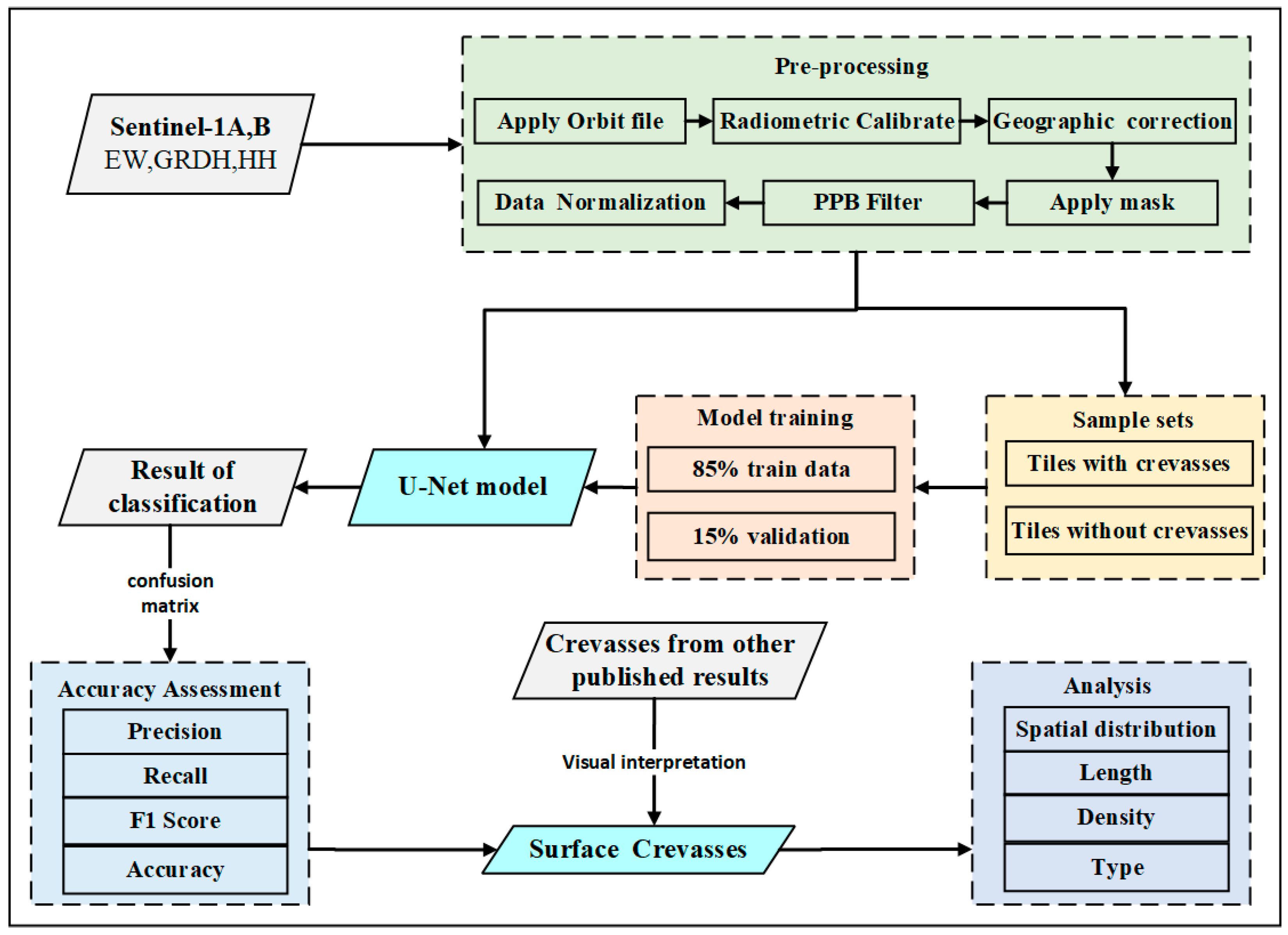
Aiming at the extraction and analysis of crevasses on typical Antarctic ice shelves, the method proposed in this study mainly comprised four processes, which were data pre-processing, deep learning model training, crevasse prediction, accuracy assessment, and statistical analysis of ice crevasses. The processing flowchart is shown in Figure 3. In the following, we first show the pre-processing in detail (Section 3.1). Then we introduce the architecture of the deep neural network used in this study and the model training (Section 3.2), as well as the accuracy assessment metrics (Section 3.3).

3.1. Pre-Processing and Data Preparation

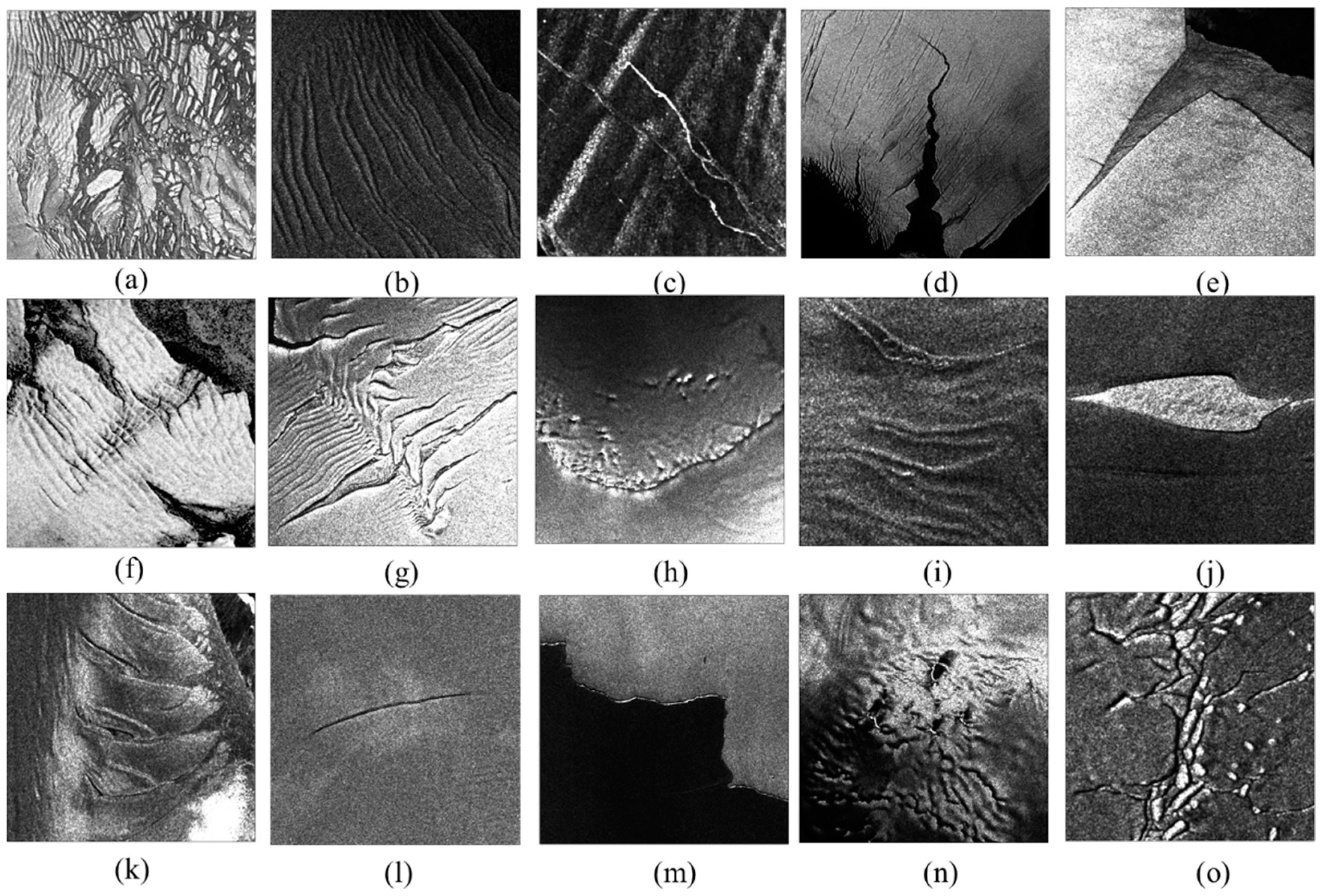
The rough surface of the crevasse usually causes it to appear as a high backscattering feature on the SAR image, showing a brighter linear feature [33]. However, as can be seen in Figure 4, Antarctic crevasses do not always appear with homogeneous high backscatter but instead with different forms of crevasses. Depending upon the reasons and types of formation, the crevasses on the glacier surface are mostly shown as Transverse Crevasses, Splaying Crevasses, Bergschrund, En échelon Crevasses, Icefall, and Rifts [1]. The dynamic reasons, characteristics, and image recognition signs of different crevasses are shown in Table 2.
Based on the above description, we intuitively selected various forms of crevasses as a supplement to the training data set, and as a result, a total 1970 pairs of samples were constructed. However, it is important to note that the crevasse types mentioned in this study mainly target six surface crevasses and do not include basal crevasses. Although basal crevasses are very important to the stability of ice shelves [34,35], the detection of basal crevasses in the current research was mainly carried out by ground-penetrating radar [36,37]. The limitation was that, on the one hand, the depth of the basal crevasse development is inconsistent under the glacier, and there is no corresponding feature on the glacier surface. On the other hand, without other prior knowledge, it is impossible to confirm whether the surface morphology of the glacier was caused by basal crevasses only by relying on SAR images. Therefore, we mainly discuss the surface crevasses that can be observed and identified.
In order to minimize the geometric distortion and information errors of remote sensing images caused by atmospheric interference and other factors, and to ensure the standardization of training data, we used Sentinel Application Platform (SNAP) software for data pre-processing prior to application. SNAP is a free and open software developed by the Sentinel Data Mission in the Copernicus Plan, which can be downloaded for free at https://step.esa.int/main/toolboxes/snap/ (Accessed: 15 January 2022).
First, the orbit files were used to update the orbit metadata. Then, radiometric calibration and filtering was performed to reduce thermal noise. Finally, geographic correction was applied. Additionally, ground line and coastline were used as mask files.
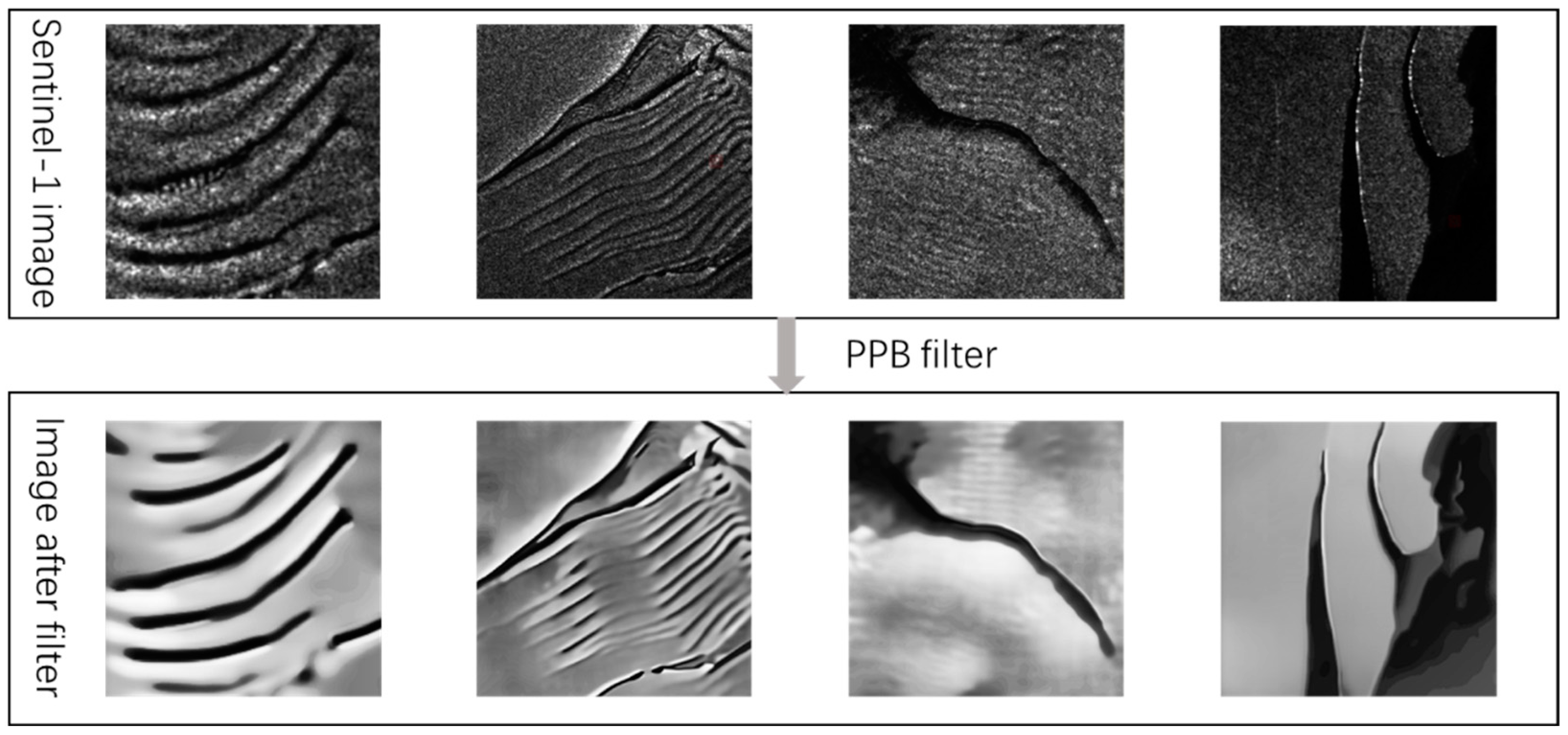
Compared with optical images, the C-band of the Sentinel-1 SAR data has higher spatial resolution and excellent coverage performance and revisit performance, but it also has a serious problem of coherent speckle noise. In order to suppress the coherent speckle noise, this study adopted the Probabilistic Patch-Based Weights algorithm (PPB) filtering method [38], which fully suppresses the coherent speckle noise and further enhances the edge. The PPB filter defines a more general and statistically based similarity criterion based on the noise distribution model. The denoising process is expressed as a weighted maximum likelihood estimation problem, in which the weights are derived in a data-driven manner. These weights can be refined based on the similarity between the current noise blocks and the noise blocks extracted from the previous iteration estimation, which sharpens the crevasse feature on the filtered images (Figure 5).
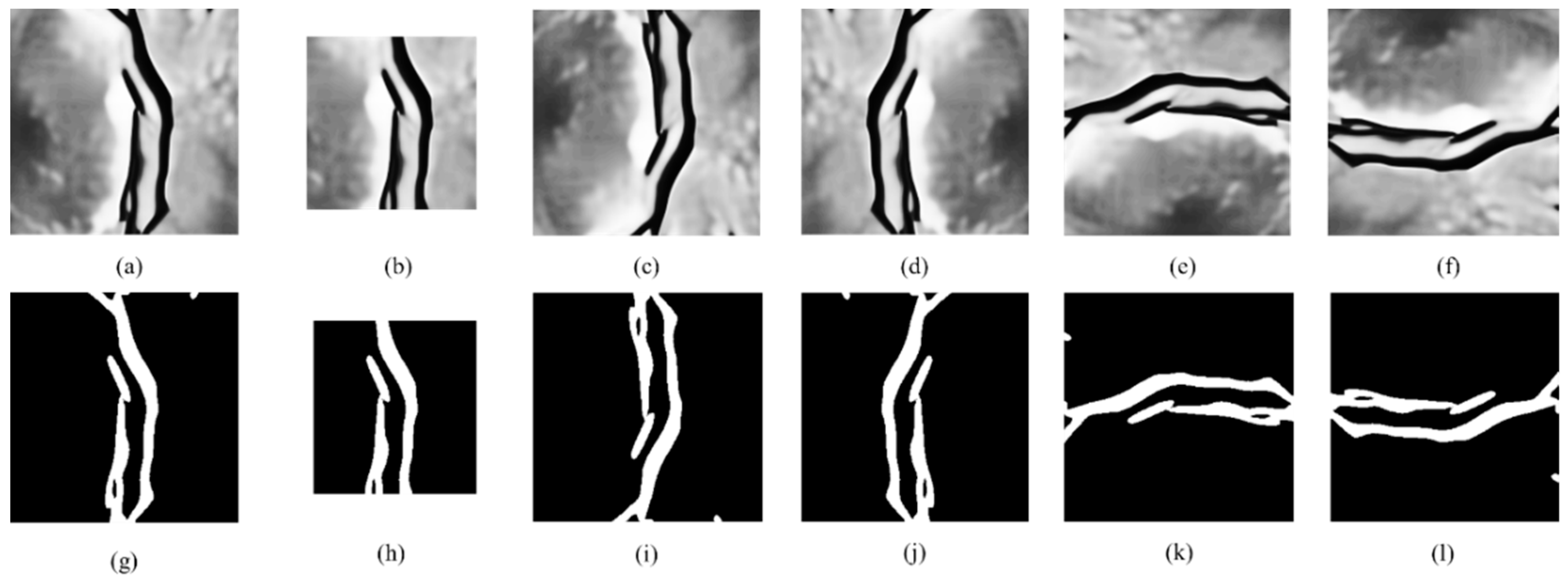
Subsequently, pixel value range was normalized by the maximum and minimum standardization. The normalization process makes the data appear dimensionless, which can prevent gradient explosion and improve the convergence speed and accuracy of the model. Because the final outcome is a binary image, there must be a corresponding mask image when model training. Figure 6 shows the mask images, in which white and black represent features of the crevasses and non-sample features, respectively. To avoid possible overfitting problems, enhancing the generalization ability and improving the accuracy of the model, a sufficient amount of data is usually needed. Data augmentation is usually used to increase the number of training samples in a data set. In this study, geometric transformation was used to enhance the training images, which mainly performed operations such as cropping, vertical flipping, horizontal transformation, and 90-degree clockwise rotation (Figure 6).
This study used the LabelMe tool to manually make labels and finally convert the labels into json format. The original and mask image were one-to-one to mark a training data set. It was necessary to ensure both positive and negative samples were stored in the training. The training set of this study had a total of 1970 pairs, and the ratio of positive and negative samples was 6:4.

3.2. U-Net Architecture and Model Training

A modified U-Net network was implemented in this study for pixel-level crevasse identification. The U-Net network was originally developed for biomedical image segmentation [39]. It is the most commonly used model in machine learning for earth observation because of the preservation of fine-grained details [40,41].
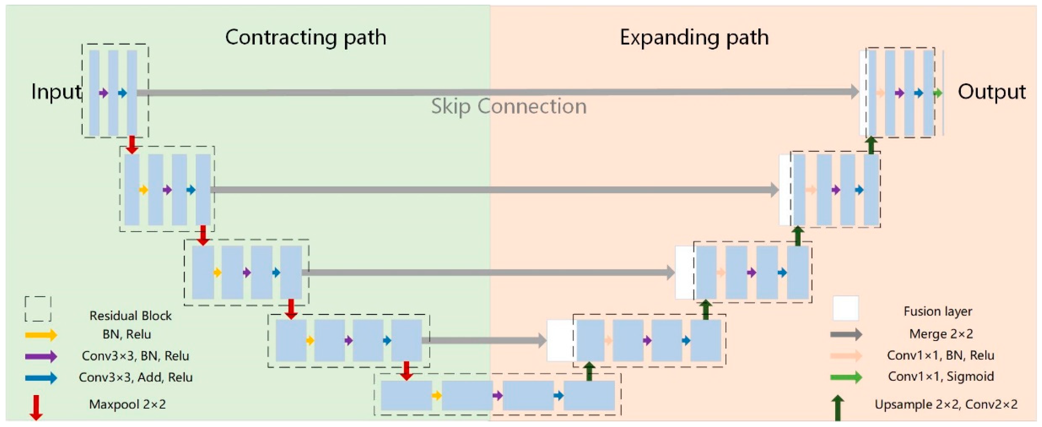
The architecture of the improved U-Net network is shown in Figure 7. It is an encoder–decoder structure.
The encoder structure, also known as the contracting path, consists of multiple encoders. One encoder mainly comprised a residual block and a pooling layer, and the final output was input into the next residual block through the maximum pooling [42]. Each residual unit of the down-sampling module had two convolutional layers, which were connected by the ReLU activation function [43]. We used two consecutive 3 × 3 convolutional layers to replace one 5 × 5 convolutional layer because both have the same receptive field [44], but the former requires fewer parameters to calculate just as much; this study chose two smaller convolution kernels instead of one larger convolution kernel. The kernel size of the largest pooling layer was 2 × 2.
The decoder structure is also called the expanding path. One decoder was composed of up-sampling, fusion layer, and residual block. Up-sampling corresponded to the pooling process, and the size was 2 × 2 [45]. The fusion layer mainly connected the feature map from the lower layer with the feature map in the corresponding contracting path to map the spatial location information of the crevasses to the semantic features. In the final stage of the expanding path, the fully connected layer in the convolutional neural network was changed to a 1 × 1 convolutional layer, and the sigmoid activation layer was used for the final classification output [46].
The modified U-Net network in this study (1) used a deconvolution layer (up-sampling 2 × 2) to replace the fully connected layer because the fully connected layer not only loses location information but also adds additional parameters [47]. The modified deconvolution layer greatly reduced the number of parameters and the difficulty of model learning and sped up operation. (2) In addition, in such a deep neural network, we added the Batch Normalization (BN) layer before the input of each layer of the network to solve the problem of imbalanced data distribution and regularize the model. This avoided overfitting as the number of layers deepened. (3) To improve the classification accuracy and avoid the phenomenon of gradient disappearance or gradient explosion in the training process [48,49], this study added skip connections after the convolutional layer. The added skip connection guaranteed the fusion of low-level local information, spatial location information of crevasses, and high-level semantic information. The information at each layer was more complete, and the characteristics of learning were more critical.
The model was compiled using the “binary cross-entropy” loss function, Adaptive Moment Estimation (Adam) optimizer, and an initial learning rate of 0.001. When the detection index is not improved, adjusting the learning rate can often achieve better results. Therefore, we set the rate within 10 epochs; if the verification loss did not improve, the learning rate would be automatically reduced by 1/e times. Finally, the model converged after 75 epochs.

3.3. Accuracy Assessment

In order to express the accuracy of the detection results, this study used four metrics: precision (P), recall rate (R), F1 score (F1), and accuracy rate (A) for assessment. Precision and Recall were derived dividing the number of true positive pixels (TP) of a given class by the total number of overall predicted class pixels or the total number of true class samples respectively. F1 score is the harmonic average of precision and recall. When the precision and recall rate are both high, the F1 value will also be high. The F1 value reaches its best value at 1, and its worst value is 0. In binary classification, the F1 value is a measure of the accuracy of the test. For the test data set, accuracy rate indicated the ratio of the number of samples correctly classified by the classifier to the total number of samples. The formulas of the four metrics are as follows:
P = T P T P + F P
R = T P T P + F N
F 1 = 2 P R P + R
A = T P + T N T P + T N + F P + F N
where TP is True Positive, which predicts the positive class as a positive class number. FP indicates False Positive, which predicts the negative class as the number of positive classes. FN is False Negative, which predicts the positive class as a negative class number. TN denotes True Negative, which predicts the negative class as the number of negative classes. The TP, FN, FP, and TN are shown in Table 3.

4. Results

4.1. Crevasse Detection Result

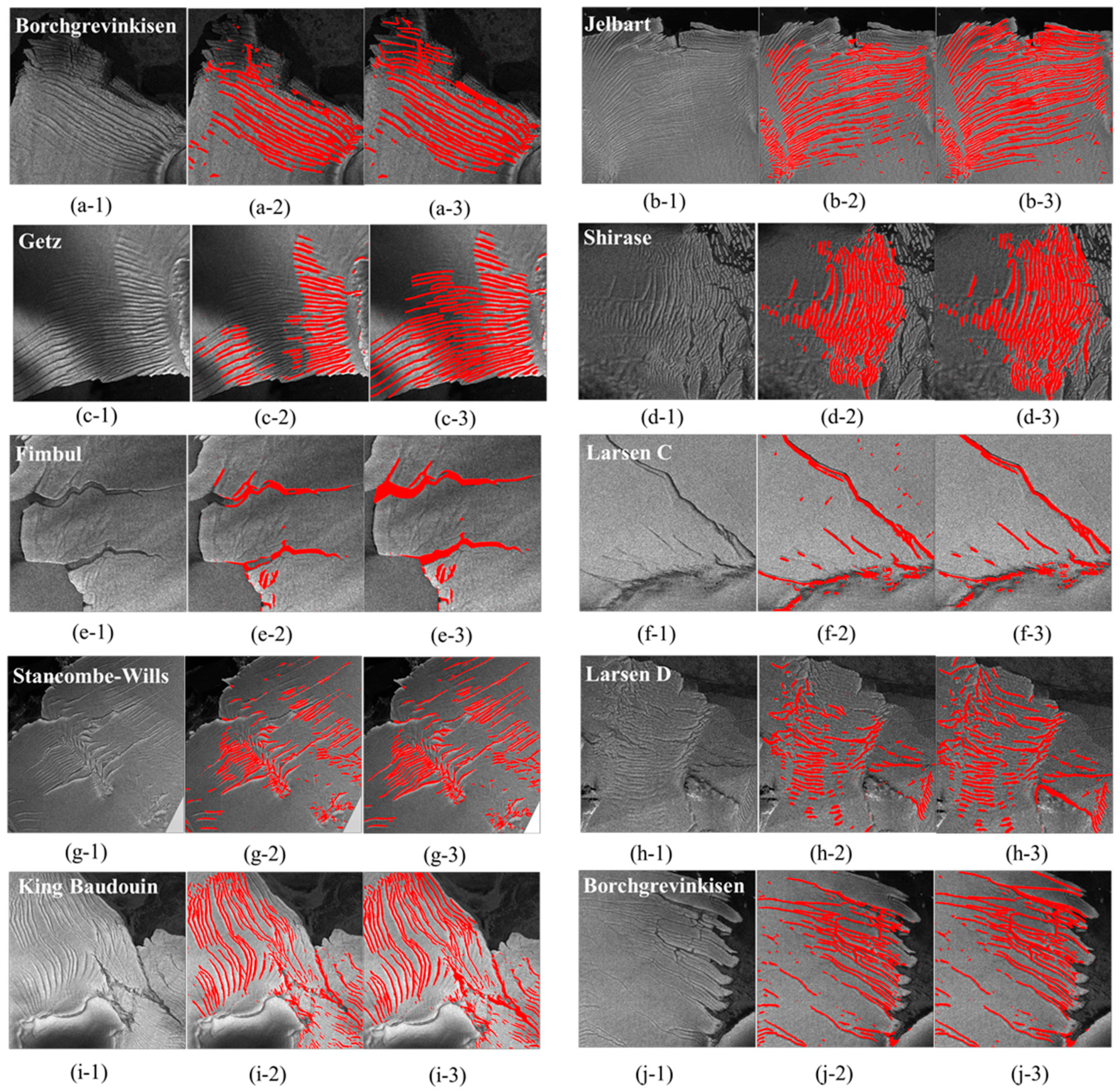
Figure 8 shows the classification results obtained by applying the automated detection algorithm of ice crevasses in this study in the test scene. It can be seen that there were certain differences in the length, type, and density of ice crevasses developed by different ice shelves. Regular and more closely spaced transverse crevasses developed on the edge of the Borchgrevinkisen Ice Shelf (Figure 8a), Jelbart Ice Shelf (Figure 8b), Getz Ice Shelf (Figure 8c), and Shirase Ice Shelf (Figure 8d). There were relatively independent rifts on the edge of the Fimbul Ice Shelf (Figure 8e) and Larsen C Ice Shelf (Figure 8f). Stancombe–Wills Ice Shelf (Figure 8g), Larsen D Ice Shelf (Figure 8h), King Baudouin Ice Shelf (Figure 8i), and Borchgrevinkisen Ice Shelf (Figure 8j) contained relatively irregular transverse crevasses, En échelon crevasses, and rifts.
In order to determine the accuracy of the automated ice crevasse extraction method proposed by this study, we visually interpreted 10 scenes from the SAR image. Within each verification area, we verified the results by producing random points. Table 4 shows the precision, recall, F1 score, and accuracy for the images in Figure 8. Overall, the accuracy was 84.23%. The average precision was 81.44%, the average recall was 72.50%, and the average F1 score was 76.02%. In some scenarios, the recall rate was low because the terrain around the crevasses, the overlying snow layer, the observation direction of the satellite, and the angle of incidence all affected the performance of the crevasses on the SAR image and brought uncertainty to the identification of the crevasses.
In the 10 test scenes, the crevasses on the Borchgrevinkisen Ice Shelf (Figure 8a), Jelbart Ice Shelf (Figure 8b), Getz Ice Shelf (Figure 8c), and Shirase Ice Shelf (Figure 8d) were relatively regular transverse crevasses at the edge of the ice shelf. Most of the crevasses in the Borchgrevinkisen Ice Shelf (Figure 8a) and Jelbart Ice Shelf (Figure 8b) were clearly identified, but some crevasses in the front edge of the ice shelf were not identified.
This may be because the ice on the front edge of the Borchgrevinkisen Ice Shelf and Jelbart Ice Shelf was thinner and affected by warm sea water; the wet snow on the surface had higher water content and higher absorption, so the backscattering coefficient was lower and the contrast on the image was lower. Therefore, the crevasse could not be clearly recognized. For the Getz and Shirase Ice Shelves, it may be that the surface crevasses were more closely spaced and the absorption of solar radiation more intense, which enhanced the surface ablation, resulting in little contrast between the crevasse area and the non-crevasse area on the image, and the crevasse could not be identified. In addition, the edge characteristics of a single crevasse in a more closely spaced area of crevasses were not obvious, which posed certain challenges to the identification of crevasses.
The crevasses on the Fimbul Ice Shelf (Figure 8e) and Larsen C Ice Shelf (Figure 8f) were relatively independent rifts with a longer length and wider width located at the edges. In a scene where the surrounding terrain is relatively flat and the type of features is single, this type of crevasse is easier to identify. However, for a single rift with a large scale, its backscattering characteristics may be inconsistent across the entire rift area, which will lead to intermittent recognition results, resulting in a low recall rate of recognition.
The accuracy of the crevasses on the Stancombe–Wills Ice Shelf (Figure 8g) was the best, probably because the incident angle was small in this scene. The angle of incidence determines the penetration depth of the radar band and the degree of perspective at the crevasse wall. The smaller the angle of incidence, the higher the contrast between the crevasse and the non-crevasse areas, which makes the identification of the crevasses easier.
Some scenes, such as the Larsen D Ice Shelf (Figure 8h), King Baudouin Ice Shelf (Figure 8i), and Borchgrevinkisen Ice Shelf (Figure 8j), had high precision and a low recall rate. This was due to the complex characteristics of the crevasses in this area, including both regular and more closely spaced transverse crevasses and large-scale single rift.
The accuracy percentages for the Fimbul Ice Shelf (Figure 8e), Larsen C Ice Shelf (Figure 8f), Stancombe–Wills Ice Shelf (Figure 8g), and Borchgrevinkisen Ice Shelf (Figure 8j) were high. This was because the crevasses’ direction was approximately perpendicular to the satellite observation direction, and the radar signal was reflected from the side wall of the crevasses, which caused the crevasses to produce high backscattering contrast relative to the surrounding ground objects. Therefore, the crevasse features were obvious and easy to distinguish.

4.2. Analysis of Crevasse Characteristics

Crevasse morphology is the external manifestation of glacier movement, and different types of crevasses reflect the characteristics of different glacier movements.
Transverse crevasses generally appear in the area of extensional flow when ice blocks slide downward from upstream. Splaying crevasses are often observed in terrestrial melting zones when the upstream ice is pushed to the downstream ice. In addition, different forms of crevasses provide different scales of glacier porosity. This will affect the mass balance of the glacier by controlling the efficiency of meltwater transportation and the hydrofracture process and destroying the stability of the ice shelf by enhancing the dynamic process of base sliding.
Crevasses play a dual role in the movement of the glacier. On the one hand, as an external manifestation of glacier movement, crevasses can indicate the process of glacier movement. For example, transverse crevasses usually develop in glacier accumulation areas [1], but in the melting zone of a glacier, a low advection life cycle splaying crevasse is more likely [50]. The En échelon crevasse is thought to be caused by the rotation of the crevasse during the advection period under the glacier in the high advection period. However, not all types of crevasses can be attributed to these two broad life cycles [9].
On the other hand, the shape of the crevasse will also affect the melting of the glacier surface [51]. The latent heat carried by the surface meltwater affects the ice deformation [52,53], and the resulting hydrofracture may also cause glaciers to collapse [6]. The disintegrated glacier lacks frontal barriers, and the ice flow speeds up. The development of potential crevasses and the process of glacier deformation form a cyclic feedback mode [1].
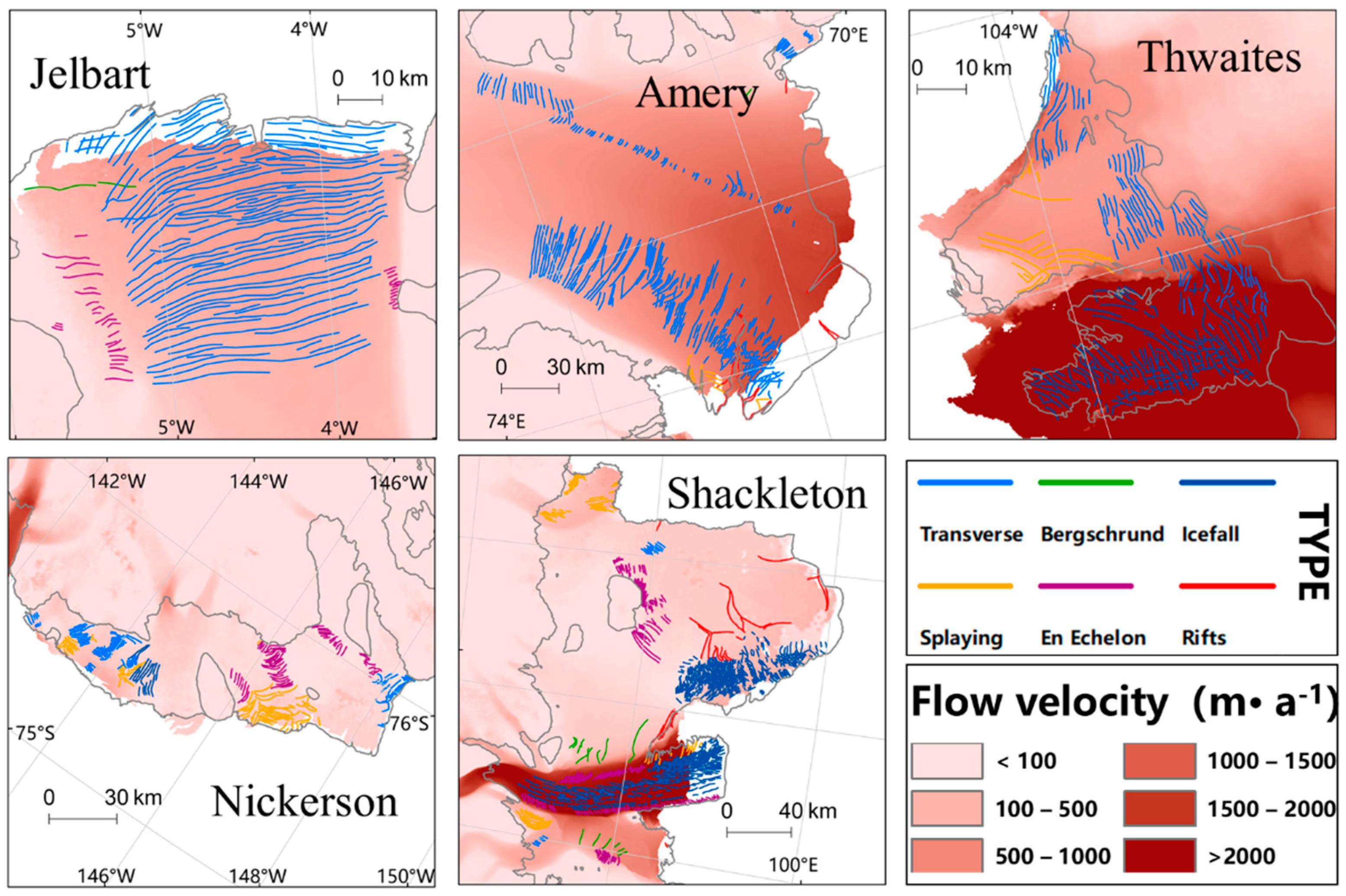
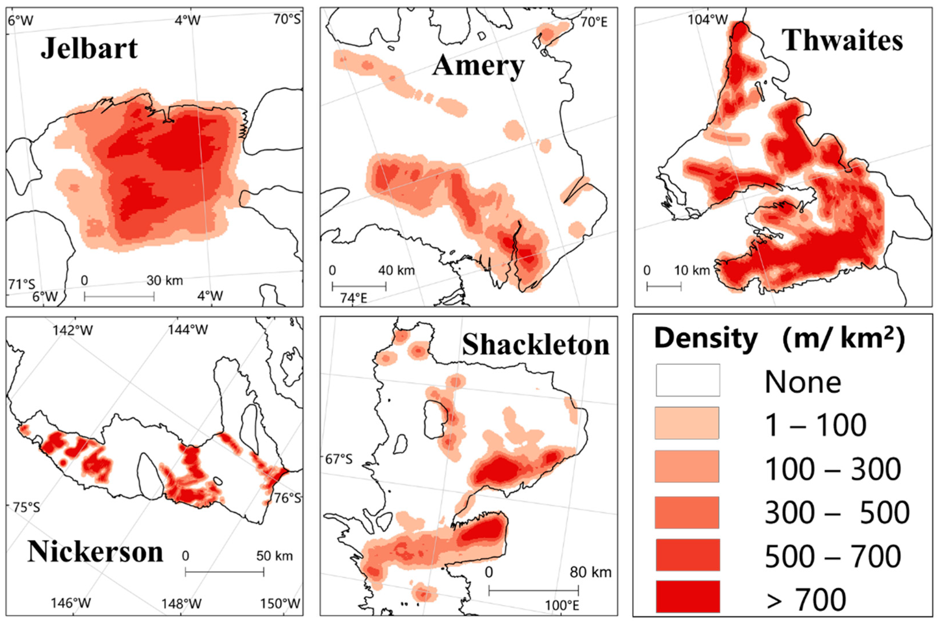
However, there have been no detailed products of crevasse morphology. Given the importance of the type of crevasse, we used a visual interpretation method based on prior knowledge to distinguish the types of crevasses. We divided the surface crevasses into six types according to the morphological characteristics, and we calculated the length as well as density characteristics of ice crevasses. Furthermore, we discussed the composition and spatial distribution of ice crevasses in different ice shelves, including the Thwaites Glacier and Nickerson Ice Shelf in WAIS, and the Jelbart Ice Shelf, Amery Ice Shelf, and Shackleton Ice Shelf in EAIS. The spatial distribution of different types of ice crevasses is shown in Figure 9.
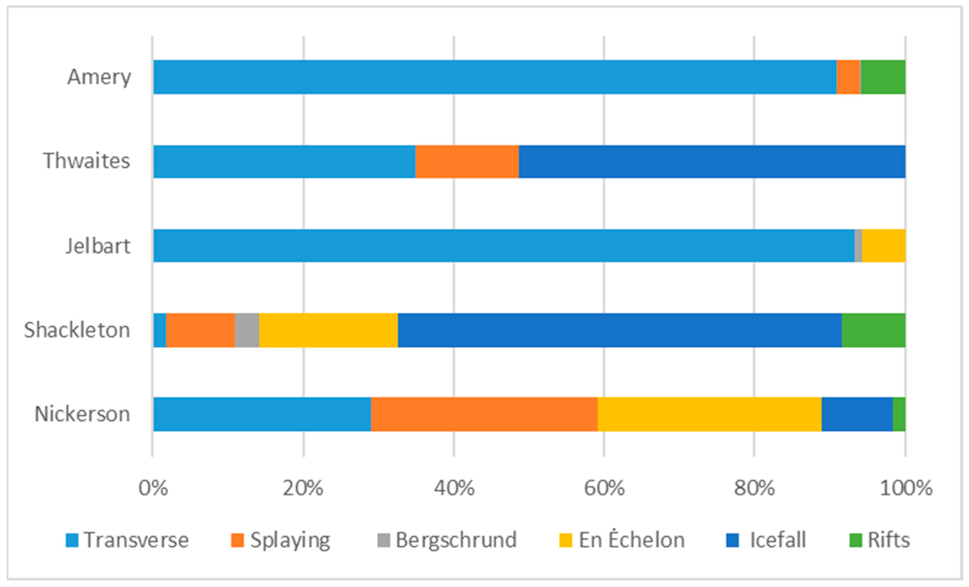
There are also spatial differences in the type and composition of ice crevasses (Figure 10). The types of ice crevasses on the Amery Ice Shelf and Jelbart Ice Shelf were dominated by the transverse crevasses, while the types of ice crevasses on the Shackleton Ice Shelf and Nickerson Ice Shelf were more abundant.
On the Amery Ice Shelf, the main types of ice crevasses were transverse crevasses, in addition to a small number of splaying crevasses and fewer rifts. On the Thwaites Glacier, the crevasses were mainly icefall and secondly transverse crevasses, and splaying crevasses were also widely distributed. On the Jelbart Ice Shelf, transverse crevasses were the main crevasse type, followed by a limited number of En échelon crevasses, and the bergschrund and rifts had developed sporadically. On the Shackleton Ice Shelf, there were rich types of ice crevasses, and icefall in some areas was obvious. On the Nickerson Ice Shelf, the proportions of transverse crevasses, splaying crevasses, and En échelon crevasses were relatively balanced, and the distribution was relatively concentrated. In addition, there was a scattered distribution of rifts.
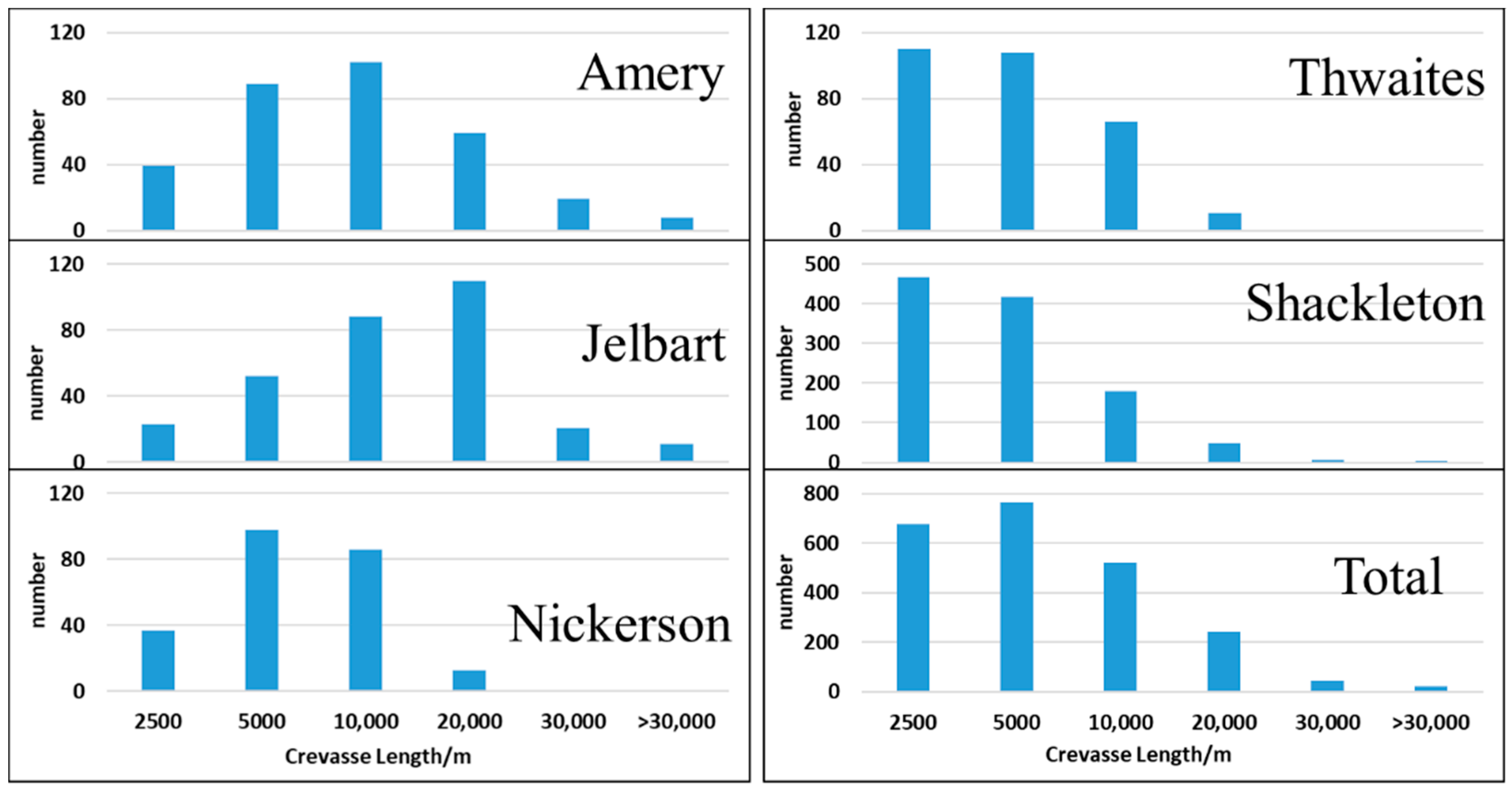
We also counted the average length and density properties of the ice crevasses, and we defined density as the length of crevasses in meters per square kilometer [54]. Table 5 and Figure 11 and Figure 12 show the length and density of ice crevasses on typical ice shelves of Antarctica.
Overall, the Jelbart Ice Shelf had the longest ice crevasses. The Shackleton Ice Shelf had the shortest ice crevasses. The spatial difference in the density of ice crevasses in the Antarctic ice shelf was relatively small. The Thwaites Glacier and the Nickerson Ice Shelf had the largest ice crevasse density, and the Amery Ice Shelf had the smallest ice crevasse density. The ice crevasses on different ice shelves showed different shapes. The ice crevasses on the Nickerson Ice Shelf and the Thwaites Glacier were short and more closely spaced; the ice crevasses on the Jelbart Ice Shelf and Amery Ice Shelf were long and sparse.
The characteristics of crevasses are important signs of glacial movement. However, we must admit that our current research technology and detection results can only reflect the main characteristics of the crevasses to a certain extent, including length, density, and type. Therefore, to carry out more quantitative research requires further optimized technical methods and higher resolution data support. In the future, we will further explore the way to achieve this and conduct a more in-depth analysis and discussion on the process and mechanism of crevasse formation.

5. Discussion

Since the brightness of the SAR image is proportional to the backscattering intensity, bright pixels correspond to rough glacier surfaces while dark pixels indicate smooth surfaces [55]. However, a rough glacier surface includes not only crevasses but also surface features such as thinning of the top snow layer, formation of ridges, and steep slopes. These features will increase the complexity of crevasse extraction and interfere with the accurate extraction of ice crevasses to a certain extent.
Undoubtedly, the training samples and the model’s inherent configuration all contributed to the error of the extraction method. Although we considered the different types of crevasse appearances in the single-polarized Sentinel-1 SAR imagery in the training samples, there remained some complex situations where we could not discriminate the crevasses from the surrounding surface. Based on the above considerations, we used a visual interpretation method based on prior knowledge to distinguish the types of crevasses. More models based on machine learning method that have been widely used in cryosphere studies [45,56] would be considered in attempting to improve the accuracy of crevasses’ detection in future work.
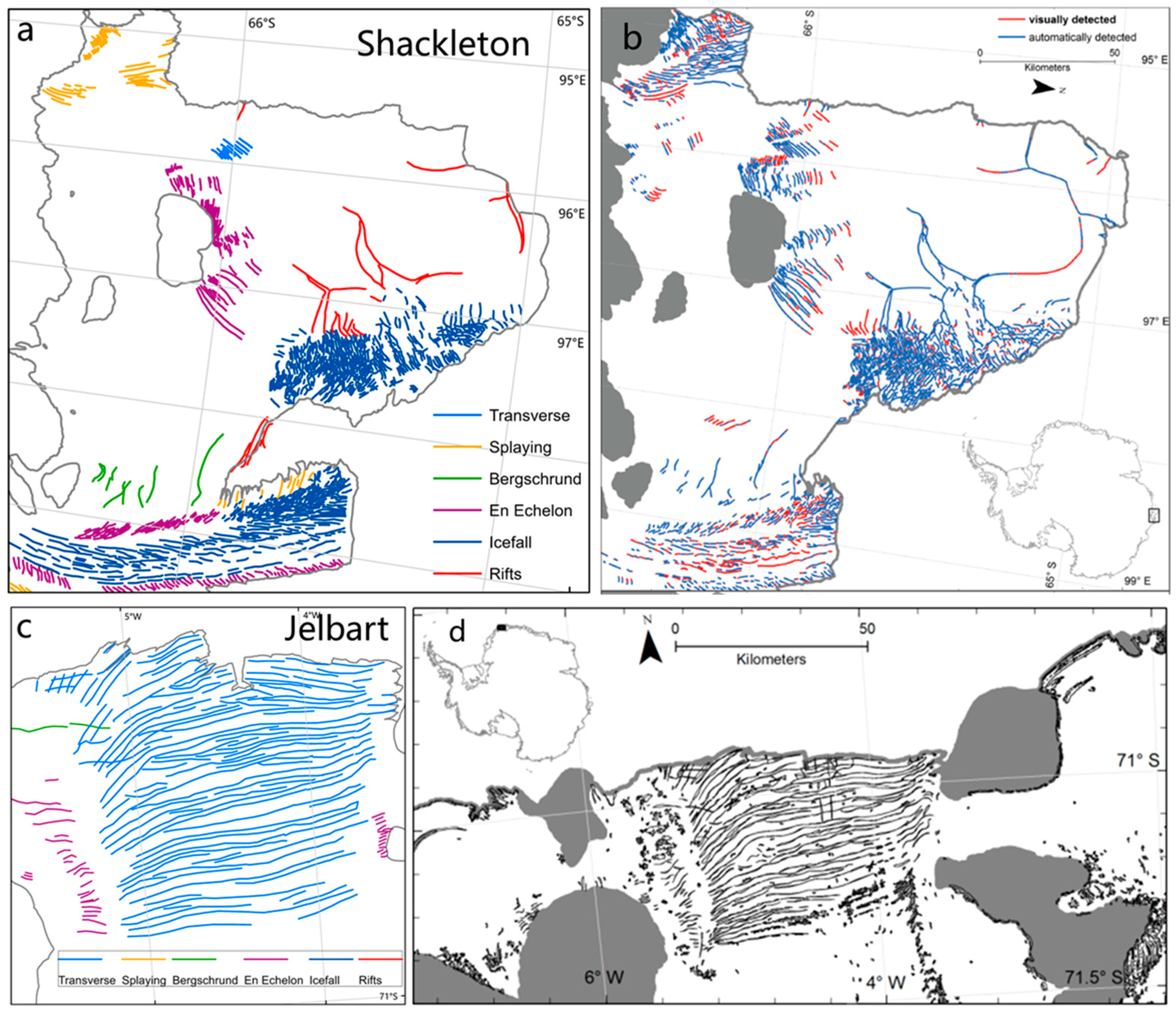
In order to further verify the crevasse detection method proposed in this study, we selected the typical crevasse area of the Shackleton Ice Shelf and Jelbart Ice Shelf and compared it with results from published literature. The results showed that, regardless of the unrecognizable crevasses caused by the image quality and the changes in the crevasses themselves, except for the collapse of the edge of the ice shelf caused by the expansion of the rift, the identification of the crevasses in other areas had good visual consistency (Figure 13).
The comparison results showed that the ice crevasses detected by our method were generally consistent with the results of Christine et al. (2013), but there were still some differences in the identification of crevasses. This was because, on the one hand, the sensors that collected the data were different. Christine et al. (2013) used Radarsat-1 data with better spatial resolution (25 m), so the identification of some small crevasses was more accurate. On the other hand, data collection time was different. The data collection time of Christine occurred before 2013, and the Sentinel-1 data we used were from 2020. The comparison showed that the edge of the Shackleton Ice Shelf collapsed from the expansion of the rift during 2013–2020.

6. Conclusions

Crevasses play an important dual role in indicating glacier movement and the collapse of ice shelves. On the one hand, they are the external manifestation of glacier movement. Crevasses of different shapes reflect the movement characteristics of different glaciers. On the other hand, crevasses with different shapes developed in different ice-forming zones have different effects on the mass balance of the glacier surface and the stability of the ice shelf. Therefore, it is important to identify the spatial pattern and features of ice crevasses.
In this study, we used the improved U-Net network for the deep learning model training and test and realized the automated detection of Antarctic ice crevasses based on single-polarized Sentinel-1 SAR data. According to the detection results of typical ice shelves in Antarctica, our detection method achieved a local accuracy of 95%, which proved the feasibility and reliability of the application of the single-polarization SAR image and deep learning method to Antarctic ice crevasse detection. Compared with previous studies, the identification of the crevasse areas had good visual consistency. Based on the identification of ice crevasses, we initially calculated the length, density of ice crevasses, and manually determined the type characteristics in various regions of Antarctica, reflecting the regional differences in the appearance of ice crevasses.
Although we considered the morphological differences of the types of ice crevasses when building the training samples, the current method could only identify that they were crevasses without determining the type of crevasse. However, the proposed method has some limitations in distinguishing complex crevasses. In the next study, we intend to improve the detection accuracy by increasing the diversity of training samples and adjusting the configuration of the model. More importantly, we will analyze the development characteristics of different types of ice crevasses and the influence process on the stability of the ice shelf using the long-time scale and high spatial resolution crevasse products, to further reflect the response mechanism of the glacier mass balance and to provide scientific solutions for actively responding to global climate change.

Author Contributions

Methodology, Y.D., L.L., and J.Z.; software, J.Z.; validation, J.Z.; resources, J.Z.; writing—original draft preparation, J.Z.; writing—review and editing, S.L., J.Z., and X.L.; funding acquisition, X.L. All authors have read and agreed to the published version of the manuscript.

Funding

This research was funded by the National Key Research and Development Program of China under Grant 2019YFC1509104 and the Strategic Priority Research Program of the Chinese Academy of Sciences under Grant XDA19070202.

Institutional Review Board Statement

Not applicable.

Informed Consent Statement

Not applicable.

Data Availability Statement

Data available on request.

Acknowledgments

The authors would like to thank the European Union Copernicus Program for providing Sentinel-1 data through the Copernicus Open Access Hub and NASA’s Alaska Satellite Facility (ASF). Moreover, we thank the North American Cartographic Information Society (NACIS) for providing the Antarctic ice shelf data.

Conflicts of Interest

The authors declare no conflict of interest.

References

  1. Colgan, W.; Rajaram, H.; Abdalati, W.; McCutchan, C.; Mottram, R.; Moussavi, M.S.; Grigsby, S. Glacier crevasses: Observations, models, and mass balance implications. Rev. Geophys. 2016, 54, 119–161. [Google Scholar] [CrossRef]
  2. Herzfeld, U.C.; Trantow, T.; Lawson, M.; Hans, J.; Medley, G. Surface heights and crevasse morphologies of surging and fast-moving glaciers from ICESat-2 laser altimeter data—Application of the density-dimension algorithm (DDA-ice) and evaluation using airborne altimeter and Planet Sky Sat data. Sci. Remote Sens. 2021, 3, 100013. [Google Scholar] [CrossRef]
  3. Miles, K.E.; Hubbard, B.; Irvine-Fynn, T.; Miles, E.S.; Rowan, A.V. Hydrology of debris-covered glaciers in High Mountain Asia. Earth-Sci. Rev. 2020, 207, 103212. [Google Scholar] [CrossRef]
  4. Gilbert, A.; Sinisalo, A.; Gurung, T.R.; Fujita, K.; Maharjan, S.B.; Sherpa, T.C.; Fukuda, T. The influence of water percolation through crevasses on the thermal regime of Himalayan Mountain glaciers. Cryosphere 2020, 14, 1273–1288. [Google Scholar] [CrossRef] [Green Version]
  5. Yang, K. The Progress of Greenland Ice Sheet Surface Ablation Research. J. Glaciol. Geocryol. 2013, 35, 101–109. [Google Scholar]
  6. Lai, C.Y.; Kingslake, J.; Wearing, M.G.; Chen, P.H.C.; Gentine, P.; Li, H.; van Wessem, J.M. Vulnerability of Antarctica’s ice shelves to meltwater-driven fracture. Nature 2019, 584, 574–578. [Google Scholar] [CrossRef]
  7. Thompson, S.S.; Cook, S.; Kulessa, B.; Winberry, J.P.; Fraser, A.D.; Galton-Fenzi, B.K. Comparing satellite and helicopter-based methods for observing crevasses, application in East Antarctica. Cold Reg. Sci. Technol. 2020, 178, 103128. [Google Scholar] [CrossRef]
  8. Whillans, I.M.; Merry, C.J. Analysis of a shear zone where a tractor fell into a crevasse, western side of the Ross Ice Shelf, Antarctica. Cold Reg. Sci. Technol. 2001, 33, 1–17. [Google Scholar] [CrossRef]
  9. Vornberger, P.L.; Whillans, I.M. Crevasse Deformation and Examples from Ice Stream B, Antarctica. J. Glaciol. 1990, 36, 3–10. [Google Scholar] [CrossRef] [Green Version]
  10. Delaney, A.J.; Arcone, S.A.; O’Bannon, A.; Wright, J. Crevasse detection with GPR across the Ross Ice Shelf, Antarctica. In Proceedings of the Tenth International Conference on Grounds Penetrating Radar, Delft, The Netherlands, 21–24 June 2004; pp. 777–780. [Google Scholar]
  11. Taurisano, A.; Tronstad, S.; Brandt, O.; Kohler, J. On the use of ground penetrating radar for detecting and reducing crevasse-hazard in Dronning Maud Land, Antarctica. Cold Reg. Sci. Technol. 2006, 45, 166–177. [Google Scholar] [CrossRef]
  12. Williams, R.M.; Ray, L.E.; Lever, J.H.; Burzynski, A.M. Crevasse Detection in Ice Sheets Using Ground Penetrating Radar and Machine Learning. IEEE J. Sel. Top. Appl. Earth Obs. Remote Sens. 2017, 7, 4836–4848. [Google Scholar] [CrossRef]
  13. Liu, Y.; Cheng, X.; Hui, F.; Wang, X.; Wang, F.; Cheng, C. Detection of crevasses over polar ice shelves using Satellite Laser Altimeter. Sci. China Earth Sci. 2014, 57, 1267–1277. [Google Scholar] [CrossRef]
  14. Bhardwaj, A.; Joshi, P.K.; Sam, L.; Singh, M.K.; Singh, S.; Kumar, R. Applicability of Landsat 8 data for characterizing glacier facies and supraglacial debris. Int. J. Appl. Earth Obs. Geoinf. 2015, 38, 51–64. [Google Scholar] [CrossRef]
  15. Merry, C.J.; Whillans, I.M. Ice-flow features on Ice Stream B, Antarctica, revealed by SPOT HRV imagery. J. Glaciol. 1993, 39, 515–527. [Google Scholar] [CrossRef] [Green Version]
  16. Moustafa, S.E.; Rennermalm, A.K.; Román, M.O.; Wang, Z.; Schaaf, C.B.; Smith, L.C.; Erb, A. Evaluation of satellite remote sensing albedo retrievals over the ablation area of the southwestern Greenland ice sheet. Remote Sens. Environ. 2017, 198, 115–125. [Google Scholar] [CrossRef]
  17. Colgan, W.; Steffen, K.; McLamb, W.S.; Abdalati, W.; Rajaram, H.; Motyka, R.; Anderson, R. An increase in crevasse extent, West Greenland: Hydrologic implications. Geophys. Res. Lett. 2011, 38, 1–7. [Google Scholar] [CrossRef] [Green Version]
  18. Herzfeld, U.C.; Zahner, O. A connectionist-geostatistical approach to automated image classification, applied to the analysis of crevasse patterns in surging ice. Comput. Geoences 2001, 27, 499–512. [Google Scholar]
  19. Ewertowski, M.W.; Evans, D.J.; Roberts, D.H.; Tomczyk, A.M.; Ewertowski, W.; Pleksot, K. Quantification of historical landscape change on the foreland of a receding polythermal glacier, Hørbyebreen, Svalbard. Geomorphology 2019, 325, 40–54. [Google Scholar] [CrossRef] [Green Version]
  20. Liu, Y.; Moore, J.C.; Cheng, X.; Gladstone, R.M.; Bassis, J.N.; Liu, H.; Hui, F. Ocean-driven thinning enhances iceberg calving and retreat of Antarctic ice shelves. Proc. Natl. Acad. Sci. USA 2015, 112, 3263–3268. [Google Scholar] [CrossRef] [PubMed] [Green Version]
  21. Huang, R.; Jiang, L.; Wang, H.; Yang, B. A Bidirectional Analysis Method for Extracting Glacier Crevasses from Airborne LiDAR Point Clouds. Remote Sens. 2019, 11, 2373. [Google Scholar] [CrossRef] [Green Version]
  22. Enderlin, E.M.; Bartholomaus, T.C. Sharp contrasts in observed and modeled crevasse patterns at Greenland’s marine terminating glaciers. Cryosphere 2020, 14, 4121–4133. [Google Scholar] [CrossRef]
  23. Bhardwaj, A.; Sam, L.; Singh, S.; Kumar, R. Automated detection and temporal monitoring of crevasses using remote sensing and their implications in glacier dynamics. Ann. Glaciol. 2015, 57, 81–91. [Google Scholar] [CrossRef] [Green Version]
  24. Xiao, X.; Zhang, T.; Zhong, X.; Shao, W.; Li, X. Support vector regression snow-depth retrieval algorithm using passive microwave remote sensing data. Remote Sens. Environ. 2018, 210, 48–64. [Google Scholar] [CrossRef]
  25. Xiao, X.; Liang, S.; He, T.; Wu, D.; Pei, C.; Gong, J. Estimating fractional snow cover from passive microwave brightness temperature data using MODIS snow cover product over North America. Cryosphere 2021, 15, 835–861. [Google Scholar] [CrossRef]
  26. Gomez, R.; Arigony-Neto, J.; De Santis, A.; Vijay, S.; Jaña, R.; Rivera, A. Ice dynamics of union glacier from SAR offset tracking. Glob. Planet Chang. 2019, 174, 1–15. [Google Scholar] [CrossRef]
  27. Garbe, J.; Albrecht, T.; Levermann, A.; Donges, J.F.; Winkelmann, R. The hysteresis of the Antarctic Ice Sheet. Nature 2020, 585, 538–544. [Google Scholar] [CrossRef]
  28. Pandey, M.; NCPant Arora, D.; Gupta, R. A review of Antarctic ice sheet fluctuations records during Cenozoic and its cause-and-effect relation with the climatic conditions. Polar Sci. 2021, 30, 100720. [Google Scholar] [CrossRef]
  29. Dow, C.F.; Lee, W.S.; Greenbaum, J.S.; Greene, C.A.; Zappa, C.J. Basal channels drive active surface hydrology and transverse ice shelf fracture. Sci. Adv. 2018, 4, 7212. [Google Scholar] [CrossRef] [Green Version]
  30. Langley, K.; Von Deschwanden, A.; Kohler, J.; Sinisalo, A.; Matsuoka, K.; Hattermann, T.; Isaksson, E. Complex network of channels beneath an Antarctic ice shelf. Geophys. Res. Lett. 2014, 41, 1209–1215. [Google Scholar] [CrossRef]
  31. Luckman, A.; Jansen, D.; Kulessa, B.; King, E.C.; Sammonds, P.; Benn, D.I. Basal crevasses in Larsen C Ice Shelf and implications for their global abundance. Cryosphere 2012, 6, 113–123. [Google Scholar] [CrossRef] [Green Version]
  32. Pivot, F. C-Band SAR Imagery for Snow-Cover Monitoring at Tree line, Churchill, Manitoba, Canada. Remote Sens. 2012, 4, 2133–2155. [Google Scholar] [CrossRef] [Green Version]
  33. Marsh, O.J.; Price, D.; Courville, Z.R.; Floricioiu, D. Crevasse and rift detection in Antarctica from TerraSAR-X satellite imagery. Cold Reg. Sci. Technol. 2021, 187, 103284. [Google Scholar] [CrossRef]
  34. Benn, D.; Astrom, J. Calving glaciers and ice shelves. Adv. Phys. X 2018, 3, 1513819. [Google Scholar] [CrossRef] [Green Version]
  35. Cook, S.; Åström, J.; Zwinger, T.; Galton-Fenzi, B.K.; Greenbaum, J.S.; Coleman, R. Modelled fracture and calving on the Totten Ice Shelf. Cryosphere 2018, 12, 2401–2411. [Google Scholar] [CrossRef] [Green Version]
  36. Jacobel, R.W.; Christianson, K.; Wood, A.C.; Dallasanta, K.J.; Gobel, R.M. Morphology of basal crevasses at the grounding zone of Whillans Ice Stream, West Antarctica. Ann. Glaciol. 2014, 55, 57–63. [Google Scholar] [CrossRef] [Green Version]
  37. McGrath, D.; Steffen, K.; Scambos, T.; Rajaram, H.; Casassa, G.; Lagos, J.L.R. Basal crevasses and associated surface crevassing on the Larsen C ice shelf, Antarctica, and their role in ice-shelf instability. Ann. Glaciol. 2012, 53, 10–18. [Google Scholar] [CrossRef] [Green Version]
  38. Deledalle, C.; Denis, L.; Tupin, F. Iterative Weighted Maximum Likelihood Denoising with Probabilistic Patch-Based Weights. IEEE Trans. Image Process. 2009, 18, 2661–2672. [Google Scholar] [CrossRef] [Green Version]
  39. Li, R.; Liu, W.; Yang, L.; Sun, S.; Hu, W.; Zhang, F.; Li, W. DeepUNet: A Deep Fully Convolutional Network for Pixel-Level Sea-Land Segmentation. IEEE J. Sel. Top. Appl. Earth Obs. Remote Sens. 2018, 11, 3954–3962. [Google Scholar] [CrossRef] [Green Version]
  40. Hoeser, T.; Bachofer, F.; Kuenzer, C. Object Detection and Image Segmentation with Deep Learning on Earth Observation Data: A Review—Part II: Applications. Remote Sens. 2020, 12, 1667. [Google Scholar] [CrossRef]
  41. Dirscherl, M.; Dietz, A.J.; Kneisel, C.; Kuenzer, C. A Novel Method for Automated Supraglacial Lake Mapping in Antarctica Using Sentinel-1 SAR Imagery and Deep Learning. Remote Sens. 2021, 13, 197. [Google Scholar] [CrossRef]
  42. He, K.; Zhang, X.; Ren, S.; Sun, J. Deep residual learning for image recognition. In Proceedings of the IEEE Conference on Computer Vision and Pattern Recognition, Las Vegas, NV, USA, 27–30 June 2016; pp. 770–778. [Google Scholar]
  43. Glorot, X.; Bordes, A.; Bengio, Y. Deep sparse rectifier neural networks. In Proceedings of the Fourteenth International Conference on Artificial Intelligence and Statistics, Fort Lauderdale, FL, USA, 11–13 April 2011. [Google Scholar]
  44. Simonyan, K.; Zisserman, A. Very deep convolutional networks for large-scale image recognition. arXiv 2014, arXiv:1409.1556. [Google Scholar]
  45. Baumhoer, C.A.; Dietz, A.J.; Kneisel, C.; Kuenzer, C. Automated Extraction of Antarctic Glacier and Ice Shelf Fronts from Sentinel-1 Imagery Using Deep Learning. Remote Sens. 2019, 11, 2529. [Google Scholar] [CrossRef] [Green Version]
  46. Li, Q.J.; Zhao, Y.Q.; Gu, Z. Design of loss function for cost-sensitive learning. Control Theory Appl. 2015, 32, 689–694. [Google Scholar]
  47. Ronneberger, O.; Fischer, P.; Brox, T. U-Net: Convolutional Networks for Biomedical Image Segmentation. In Medical Image Computing and Computer-Assisted Intervention—MICCAI 2015; Springer International Publishing: Cham, Switzerland, 2015. [Google Scholar]
  48. Szegedy, C.; Vanhoucke, V.; Ioffe, S.; Shlens, J.; Wojna, Z. Rethinking the inception architecture for computer vision. In Proceedings of the IEEE Conference on Computer Vision and Pattern Recognition, Las Vegas, NV, USA, 27–30 June 2016; pp. 2818–2826. [Google Scholar]
  49. Nielsen, M.A. Neural Networks and Deep Learning; Determination Press: San Francisco, CA, USA, 2015; Volume 25. [Google Scholar]
  50. Mottram, R.; Benn, D. Testing crevasse-depth models: A field study at Breiðamerkurjökull, Iceland. J. Glaciol. 2009, 55, 746–752. [Google Scholar] [CrossRef] [Green Version]
  51. Cathles, L.M.; Abbot, D.S.; Bassis, J.N.; MacAyeal, D. Modeling surface-roughness/solar-ablation feedback: Application to small-scale surface channels and crevasses of the Greenland ice sheet. Ann. Glaciol. 2011, 52, 99–108. [Google Scholar] [CrossRef] [Green Version]
  52. Phillips, T.; Rajaram, H.; Steffen, K. Cryo-hydrologic warming: A potential mechanism for rapid thermal response of ice sheets. Geophys. Res. Lett. 2010, 37, L20503. [Google Scholar] [CrossRef]
  53. Poinar, K.; Joughin, I.; Lilien, D.; Brucker, L.; Kehrl, L.; Nowicki, S. Drainage of Southeast Greenland Firn Aquifer Water through Crevasses to the Bed. Front. Earth Sci. 2017, 5, 5. [Google Scholar] [CrossRef] [Green Version]
  54. Wesche, C.; Jansen, D.; Dierking, W. Calving Fronts of Antarctica: Mapping and Classification. Remote Sens. 2013, 5, 6305–6322. [Google Scholar] [CrossRef] [Green Version]
  55. Koike, K.; Yoshida, H.; Omura, M.; Shibuya, K.; Doi, K. Temporal changes in crevasses in the middle Slessor Glacier, Coats Land, East Antarctica through SAR data analysis. Earth Planets Space 2012, 64, 257–267. [Google Scholar] [CrossRef] [Green Version]
  56. Xiao, X.; He, T.; Liang, S.; Zhao, T. Improving fractional snow cover retrieval from passive microwave data using a radiative transfer model and machine learning method. IEEE Trans. Geosci. Remote Sens. 2021, 1. [Google Scholar] [CrossRef]
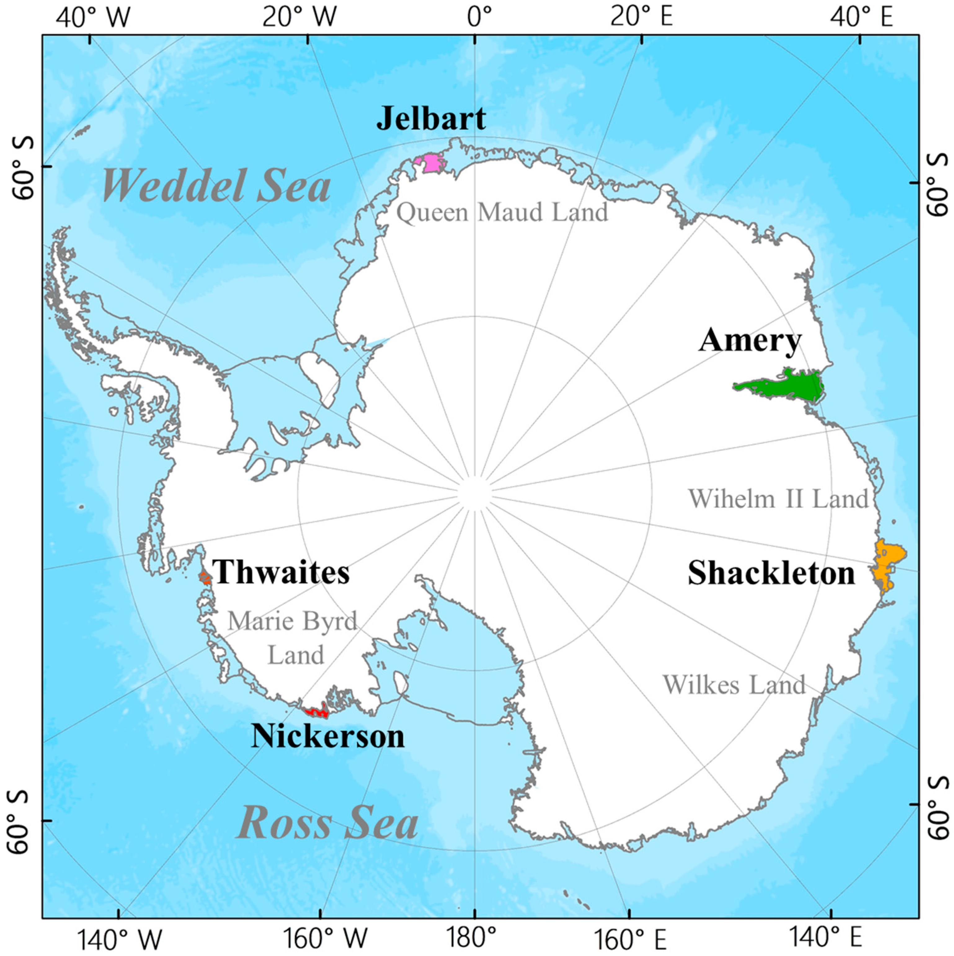
Figure 1. Sketch map of the Antarctic study areas.
Remotesensing 14 00487 g001
Figure 2. Spatial distribution of training (blue) and test (red) sites across the Antarctic continent.
Remotesensing 14 00487 g002
Figure 3. Flowchart for automated ice crevasse mapping using a deep learning approach from Sentinel-1 SAR imagery over the Antarctic ice sheet.
Remotesensing 14 00487 g003
Figure 4. Surface feature of different shaped crevasses in single-polarized Sentinel-1 imagery over Antarctica. (a) Disintegration caused by crevasses at the edge of the ice shelf. (b) Regular and more closely spaced transverse crevasses. (c) Independent rifts on the edge of the Abbot Ice Shelf. (d) Cracking rift on the Amery Ice Shelf. (e) Rift on the Amery Ice Shelf. (f,g) Transverse Crevasses on the Riiser Ice Shelf. (h) Terrain shadows. (i) En échelon Crevasses on the Riiser Ice Shelf. (j) Bergschrund on the Ronne Ice Shelf. (k) En échelon Crevasses on the Shackleton Ice Shelf. (l) Bergschrund on the Ronne Ice Shelf. (m) Front edge of the ice shelf. (n) Landform. (o) Splaying Crevasses on the Abbot Ice Shelf.
Remotesensing 14 00487 g004
Figure 5. Results of PPB filter applied to 4 Sentinel-1 SAR image. The top row is the original SAR image, and the bottom row is the corresponding filtering results.
Remotesensing 14 00487 g005
Figure 6. Training set samples after data annotation and enhancement. (a) Map of sample, (b) cropping, (c) vertical flipping, (d) horizontal transformation, (e) 90° counterclockwise, (f) 90° clockwise, bottom row is the corresponding mask of top row. (gl) is the labels corresponding to (af).
Remotesensing 14 00487 g006
Figure 7. Improved U-net network structure diagram.
Remotesensing 14 00487 g007
Figure 8. Original image, the result of ice crevasse detection and manual correction. (aj-1 is the original SAR image, aj-2 is the result of automatic crevasse identification, aj-3 is the result of manually corrected crevasses).
Remotesensing 14 00487 g008
Figure 9. Distribution of ice crevasses in typical ice shelves in Antarctica.
Remotesensing 14 00487 g009
Figure 10. The types of ice crevasses on typical ice shelves of Antarctica.
Remotesensing 14 00487 g010
Figure 11. The density of ice crevasses on typical ice shelves of Antarctica.
Remotesensing 14 00487 g011
Figure 12. The length of ice crevasses on typical ice shelves of Antarctica.
Remotesensing 14 00487 g012
Figure 13. Comparison of characteristics of crevasses on the typical ice shelves. (a,c) are the results of the method proposed in this study; (b,d) are the results from the published literature [54].
Remotesensing 14 00487 g013
Table 1. Sentinel-1 training and test regions covering the Antarctic continent.
IDTime Period/DateOrbitStudy AreaRegionOrbit Direction
Training regions
120200201T08202431,056Wilkins Ice ShelfAPIDescending
220200103T06343530,632Ronne Ice ShelfEAISDescending
320200109T22193930,729Riiser-Larsen Ice ShelfEAISAscending
420200104T20322430,655Fimbul Ice ShelfEAISAscending
520200104T13584730,651Amery Ice ShelfEAISAscending
620200101T15121230,608West Ice ShelfEAISAscending
720200104T12195930,650Totten Ice ShelfEAISAscending
820200102T09171430,619Aviator Ice ShelfEAISAscending
920200105T08010030,662Nickerson Ice ShelfWAISAscending
1020200102T04195430,616Dotson Ice ShelfWAISAscending
Test regions
120200103T08095830,633Larsen Ice ShelfAPIDescending
220200111T23394130,759Stancombe-Wills Ice ShelfEAISAscending
320200129T19345431,019Borchgrevinkisen Ice ShelfEAISAscending
420200129T19355831,019King Baudouin Ice ShelfEAISAscending
520200130T18382931,033Shirase Ice ShelfEAISAscending
620200104T15373930,652Amery Ice ShelfEAISAscending
720200105T13023130,665Shackleton Ice ShelfEAISAscending
820200105T11233430,664Holme Ice ShelfEAISAscending
920200102T09151430,619Ross Ice ShelfWAISAscending
1020200102T02425930,615Venable Ice ShelfWAISAscending
Table 2. Dynamic reasons and image recognition signs of different types of crevasses.
Type of CrevassesDynamic ReasonsImage Recognition Signs
Transverse crevasseThe longitudinal tensile stress caused by the difference in the lateral velocity of the glacier surface has a large amount of longitudinal extension, which usually bulges on the downstream side.It is manifested by the appearance of bright white lines (snow) or black lines (water filling), which are relatively regular and parallel to each other, perpendicular to the direction of glacier flow, and transverse to other features.
Splaying crevasseIt is caused by thrust faults, mainly under the condition of longitudinal compression, and secondly under the condition of lateral compression flow.Commonly found near the glacier termini. Extends sideways along the direction of glacier flow.
Bergschrund,Formed at the beginning of a glacier, the glacier pulls away from the rock wall at its head.Usually located in the upper part of the glacier, a relatively independent single crevasse.
En échelon crevassesProduced by the shear force between the valley wall and the glacier. It usually occurs at the turn of the glacier and is caused by the rotational strain of the shear zone.It is usually located on the glacier valley wall, more closely spaced, with a certain curve, forming an angle from the valley wall to the top of the glacier.
IcefallWhen the glacier flows on the convex bed, a series of crevasses are produced from the rupture of laminar flow.Along the direction of glacier flow, it is common in accumulation areas and near steep slopes.
RiftThe edge of the ice shelf is deformed and bent due to tidal motion or the active glacier tributaries merged and applied a strong lateral shear force in the inactive area, resulting in crevasses.The surface crevasses have a visible opening, usually oriented at a right angle to the direction of flow, deep enough to penetrate the entire thickness of the shelf.
Table 3. Confusion matrix.
ActualPredicted
PositiveNegative
PositiveTPFN
NegativeFPTN
Table 4. The results of the accuracy assessment for the crevasses.
ImagesPrecision (%)Recall (%)F1 (%)Accuracy (%)
Figure 8a (Borchgrevinkisen Ice Shelf)87.5056.7668.8581.00
Figure 8b (Jelbart Ice Shelf)77.0880.4378.7280.00
Figure 8c (Getz Ice Shelf)64.2945.0052.9468.00
Figure 8d (Shirase Ice Shelf)79.1786.3682.6183.84
Figure 8e (Fimbul Ice Shelf)76.9258.8266.6790.00
Figure 8f (Larsen C Ice Shelf)77.2789.4782.9392.86
Figure 8g (Stacombe-Wills Ice Shelf)94.4491.8993.1595.00
Figure 8h (Larsen D Ice Shelf)87.8863.0473.4278.79
Figure 8i (King Baudouin Ice Shelf)74.3672.5073.4278.79
Figure 8j (Borchgrevinkisen Ice Shelf)95.4580.7787.5094.00
Average 81.4472.5076.0284.23
Table 5. The average length and density of crevasses on typical ice shelves of Antarctica.
LocationsAmeryThwaitesJelbartShackletonNickerson
Length (m)8476407511,30038804922
Density (m/km2)297411367308377
Publisher’s Note: MDPI stays neutral with regard to jurisdictional claims in published maps and institutional affiliations.