Article

Relative Pose Estimation of Non-Cooperative Space Targets Using a TOF Camera

1
Shanghai Institute of Technical Physics, Chinese Academy of Sciences, Shanghai 200083, China
2
University of Chinese Academy of Sciences, Beijing 100049, China
3
Key Laboratory of Intelligent Infrared Perception, Shanghai Institute of Technical Physics, Chinese Academy of Sciences, Shanghai 200083, China
*
Author to whom correspondence should be addressed.
Remote Sens. 2022, 14(23), 6100; https://doi.org/10.3390/rs14236100
Submission received: 3 November 2022 / Revised: 28 November 2022 / Accepted: 30 November 2022 / Published: 1 December 2022
(This article belongs to the Special Issue Autonomous Space Navigation)

Abstract

:
It is difficult to determine the accurate pose of non-cooperative space targets in on-orbit servicing (OOS). The visual camera is easily affected by the extreme light environment in space, and the scanning lidar will have motion distortion when the target moves at high speed. Therefore, we proposed a non-cooperative target pose-estimation system combining a registration and a mapping algorithm using a TOF camera. We first introduce the projection model of the TOF camera and proposed a new calibration method. Then, we introduce the three modules of the proposed method: the TOF data preprocessing module, the registration module and the model mapping module. We assembled the experimental platform to conduct semi-physical experiments; the results showed that the proposed method has the smallest translation error 8 mm and Euler angle error 1° compared with other classical methods. The total time consumption is about 100 ms, and the pose tracking frequency can reach 10 Hz. We can conclude that the proposed pose-estimation scheme can achieve the high-precision pose estimation of non-cooperative targets and meet the requirements necessary for aerospace applications.

1. Introduction

In recent years, active debris removal (ADR) [1,2] and on-orbit servicing (OOS) [3,4,5,6] (lifetime extension [7] and faulty satellite repairs [8]) trials have been carried out many times. The targets in these tasks include many non-cooperative [9] aims, such as space debris [10] and dysfunctional satellites; however, the pose information of the targets cannot be provided because there are no cooperative marks [11]. Therefore, the pose estimation of non-cooperative targets plays an increasingly important role in these missions.
In order to obtain the pose when approaching a target, various electro-optical sensors, such as visual cameras [12], infrared cameras [13], LiDAR [14,15] and time-of-flight (TOF) cameras [16,17] are options. In space, sunlight changes greatly and target surfaces are always covered with special material without texture; thus, visual cameras cannot work well in these conditions, but active sensors [18] are robust in these conditions. Compared with LiDAR, TOF cameras have attracted widespread attention due to the advantages of compact structure and low power consumption [19] in the field of the pose estimation of non-cooperative targets. Moreover, the area array detectors of TOF cameras provide the range image [20] and 3D point cloud of the target surface in one frame without motion-induced distortion instead of scanning. Taking into account the above factors, a TOF camera was used to estimate the pose of the target in this study.
Pose estimation using 3D point cloud data obtained with a TOF camera mainly includes two steps: pose initialization and pose tracking. Pose initialization is generally performed by matching with a known target model, but in practical applications, the model point cloud of the target cannot be obtained in advance, and a simplified model of the target may need to be reconstructed online. Opromolla et al., designed a 3D template matching method [21], and proposed the model-based pose-estimation method [22]. Pose tracking follows the continuous pose of the target, and includes the 3D point cloud feature matching method, 3D point cloud direct registration method, and deep neural network automatic coding method. For feature matching method, Martinez et al. [23] proposed a pose-estimation method based on TOF cameras, using some typical components (e.g., cylinders and planar structures) on the target to sense the evolution of the target’s pose between frames. However, the verification experiment uses simulation data, which cannot simulate the noise generated by detecting real targets. Sun et al. [24] proposed a method based on feature information fusion and they locate satellites by detecting elliptical contours. However, the time consumption and detection accuracy of ellipse detection are unsatisfactory. Zhang et al. [25] realized that the star-arrow docking ring is a ubiquitous structure on space vehicles and converted the point cloud into a grayscale image and then estimated the relative pose by detecting the contour feature of the docking ring. Zhao et al. [26] proposed a LiDAR-based pose tracking method by fusing depth maps and point clouds. The position error is less than 1 cm. However, it obtains the relative pose by aligning the simplified sparse point cloud with the known target model point cloud. For 3D point cloud direct registration method, Wang et al. [27] used the ICP method to perform point cloud registration between every two frames, which were acquired by the TOF camera and filtered by the corresponding point median filtering approach, and the proposed approach may not be applicable to the tumbling targets and targets with high rotational speeds. Kang et al. [28] proposed a point cloud registration method using covariance matrix transform and designed a non-cooperative spacecraft pose-estimation scheme without feature extraction, but the time consumption is relatively high. For the deep neural network method, Liu et al. [29] proposed a Position Awareness Network (PANet) for spacecraft pose estimation, but the amount of calculation of extracting the key points and constructing local structural descriptors is too large, so this solution is not suitable for use in navigation systems that need to output poses in real time.
In this paper, a pose-estimation method using a TOF camera for non-cooperative targets in close-proximity operations is proposed. The proposed method does not depend on the model [21,22] or typical components [23,24,25,26] and significantly outperforms the workflow of other classical registration algorithms (ICP [30], GICP [31], NDT [32]). A new edge-preserving filtering algorithm with adaptive window and an improved ICP algorithm using different error metric are proposed, which ensure the robustness of frame-to-frame registration. Furthermore, keyframes are created to update the global model to reduce the cumulative error, the method not only avoids the linear growth of points in the global model, but also reduces both time and memory consumption.
The remainder of this paper is organized as follows. Section 2 describes in detail the pipeline of the proposed pose-estimation method. Specifically, it introduces the preprocessing module, frame-to-frame module, and model-to-frame module. In Section 3, the ground semi-physical experimental platform was built, and the performance of the proposed pose-estimation method are evaluated through the results of the semi-physical experiments. Finally, the conclusions are drawn in Section 4.

2. Architecture of the Proposed Method

In this section, the pipeline of the non-cooperative target pose-estimation system combining a registration and a mapping algorithm is introduced. As shown in Figure 1, the system can be divided into three modules: the TOF data preprocessing module, the registration frame-to-frame module, and the model mapping module.

2.1. TOF Camera Projection Model

The raw data obtained by the TOF camera include range image and near-infrared intensity values; the data are stored by image index. Therefore, we need to calibrate the camera and calculate the imaging center ( c x , c y ) and focal length ( f x , f y ) . These parameters represent the image projection model expressed by Equations (1) and (2), which is used to convert the coordinates between the range image and 3D point cloud.
u v 1 d I = f x 0 c x 0 0 0 f y c y 0 0 0 0 1 0 0 0 0 0 1 0 0 0 0 0 1 X c / Z c Y c / Z c 1 Z c I = f x X c Z c + c x f y Y c Z c + c y 1 Z c I
P c = ( u c x ) d f x ( v c y ) d f y d I = X C Y C Z C I = [ R | t ] X w Y w Z w I = T X w Y w Z w I
where ( u , v ) is the image coordinate, d is the range value and I is the intensity value. ( X c , Y c , Z c ) and ( X w , Y w , Z w ) correspond to the camera coordinate system and the global coordinate system, respectively. t represents the translation vector and R S O ( 3 ) is the rotation matrix which can be expressed by Equation (3), which is an intrinsic rotation whose Euler angles are α, β, and γ, about axes Z, Y, and X, respectively.
R = R Z ( α ) R Y ( β ) R X ( γ ) = r 11 r 12 r 13 r 21 r 22 r 23 r 31 r 32 r 33
The Euler angles can be computed by Equation (4),
γ = arctan r 32 , r 33 β = arctan r 31 1 r 31 2 α = arctan r 21 , r 11
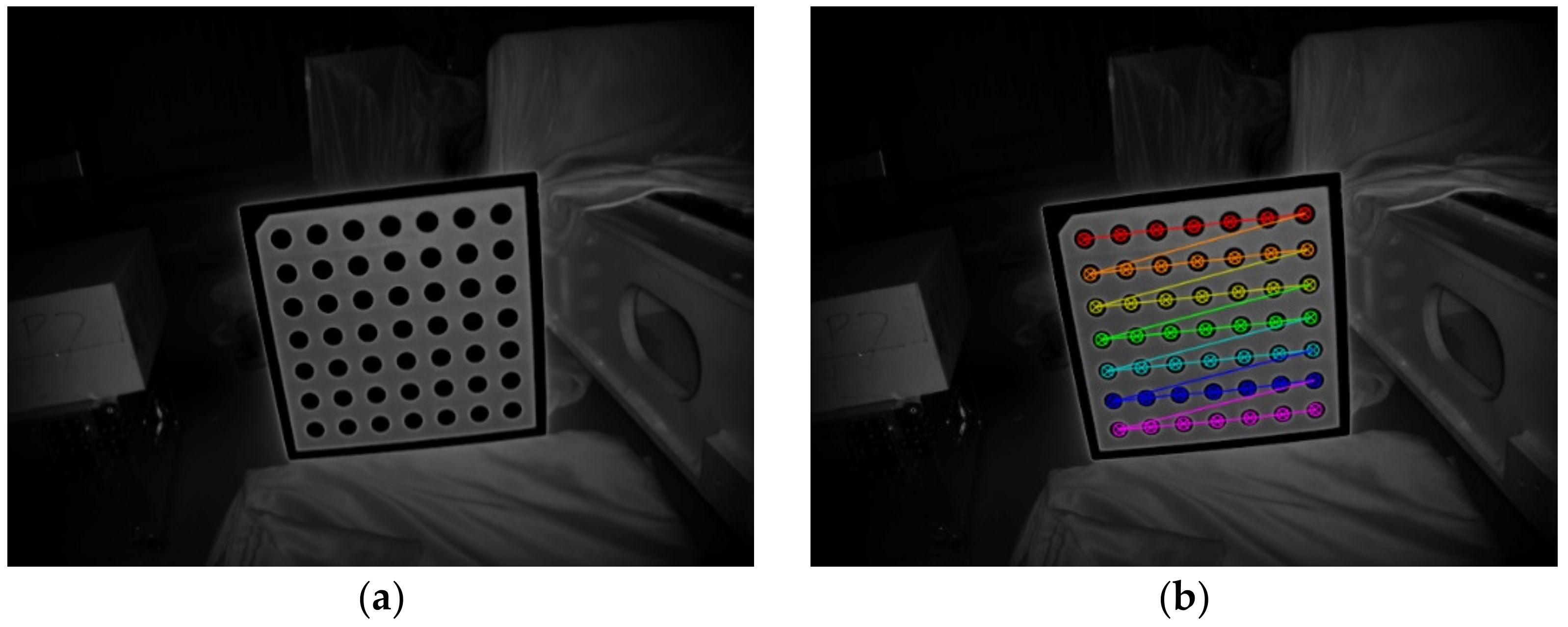
In this study, a special material was used for the origin calibration plate. The circle and the background plate had characteristics of light absorption and diffuse reflection, respectively. As shown in Figure 2, we could easily calibrate the camera by detecting a circle from the near-infrared intensity image.
The intrinsic parameters of the TOF camera are shown in Table 1.

2.2. TOF Data Preprocessing Module

2.2.1. Noise Reduction

Raw data obtained with TOF cameras are usually noisy. In order to reduce the effect of noise, we need to remove the outliers and use smoothing for the remaining data, which can improve the accuracy of subsequent pose estimations for non-cooperative targets.
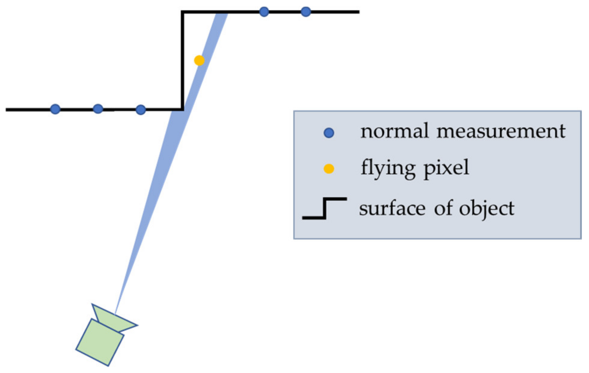
Noise is greatest at the junction of the foreground and background of an object, at pixels called flying pixels. As shown in Figure 3, the main reason for flying pixels [33] is that each pixel in the TOF sensor has a certain physical size. When measuring the edge of an object, a single pixel will receive the light reflected from the foreground and background at the same time, and the energy generated by the two will be superimposed together; thus, the raw data obtained by the sensor contain multiple distance information.
In this study, we located these pixels and then marked these pixels as invalid values instead of deleting them directly. In the subsequent smoothing process, we took advantage of the organized nature [34] of the TOF camera point cloud data; thus, we could find the nearest neighbors in the image space index instead of using the kd tree, which is much faster. The criteria to distinguish flying pixels can be expressed by Equation (5), where d ( u , v ) represents the depth value of the point ( u , v ) in the image space index, d x ( ± 1 ) and d y ( ± 1 ) represent the points at distance 1 in the same row or column as d ( u , v ) , N a N represents an invalid value, T f is a threshold related to precise of range image, and “ | | ” represent “logical-OR”.
d ( u , v ) = N a N i f d ( u , v ) d x ( ± 1 ) > T f | | d ( u , v ) d y ( ± 1 ) > T f d ( u , v ) o t h e r w i s e
Another noise reduction method using intensity information was also used in this paper. This method sets a minimum threshold for the intensity information of each point. If the intensity value of the point is lower than the threshold, it will be deleted because the low SNR (signal-to-noise ratio).

2.2.2. Edge Preserving Filter

In the smoothing process of TOF data, we need to avoid smoothing the target edge; therefore, we propose an edge-preserving filtering algorithm which uses an adaptive smoothing window to reduce the window size near the edge, so that it will not smooth foreground and background data.
We first simply detected the possible edges of the range image using Equation (6), where T p is a threshold which defines the sensitivity of range value fluctuations on a plane [35].
e ( u , v ) = 1 i f d x ( + 1 ) d x ( 1 ) > T p | | d y ( + 1 ) d y ( 1 ) > T p 0 o t h e r w i s e
Subsequently, a binary image is created; then, the distance transformation [36] function is utilized to calculate γ ( u , v ) as the distance from the point ( u , v ) to the nearest edge of the binary image. The smoothing window size of point ( u , v ) can be computed as
R ( u , v ) = min ( w 1 2 , γ ( u , v ) 2 ) ,
where the function min ( ) returns the minimum of the input parameters and w is a common window size widely used in image processing such as 5, 7, 9, etc.
In addition, the raw data acquired with a TOF camera contain intensity values [37], which can be used to indicate the accuracy of distance measurements; thus, we regard the intensity values as weights in the smoothing process. An adaptive ( 2 R + 1 ) × ( 2 R + 1 ) spatial filter can be implemented, such as Equation (8), where the weights are multiplied with intensity at the point ( u , v ) : R is R ( u , v ) .
D q = 1 W q p R q G p D p I p = 1 p R q G p I p p R q G p D p I p
where D q is the output of the filter at the point of q ( u , v ) , p R q is the point p within distance R from q ( u , v ) , G p = 1 2 π σ 2 e p q 2 2 σ 2 is a Gaussian kernel function, D p is the real depth of p , I p is the intensity value of p , W q = p R G p I p is the sum of the weights in the filtering window, which is used for the normalization of the weights, and is the Hadamard product.
In this paper, the edge-preserving filtering method is compared with other advanced algorithms. The comparison method is to filter 100 images to obtain the average time. This comparison test was implemented on a PC (I7-7700 at 2.8 GHz, 8 GB RAM) with Visual Studio 2019. The programming language was C++. We use different methods to process the same data, and the time consumption is only for the data used in this article.
The comparison results are as Table 2
In terms of accuracy, the above several edge-preserving filtering methods have basically the same impact on the final pose-estimation results, and the errors between them are within 0.1%.

2.2.3. Salient Point Selection

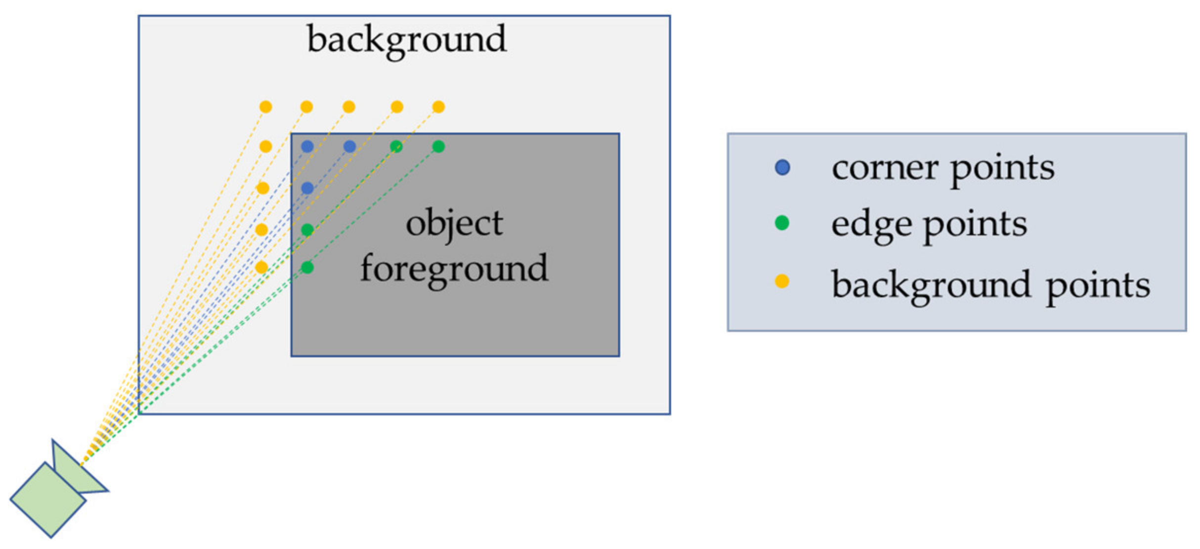
The resolution of the TOF camera in this study was 640 × 480, i.e., each frame of raw data obtained by TOF camera contained 307,200 points. Aligning such a large number of points between every two frames is very time consuming. Therefore, several criteria were adopted to select salient points from the raw data. As shown in Figure 4, these salient points were located at the connection between the foreground and the background of the object and could be divided into three categories: corner points, edge points, and background points.
Compared with corner points and edge points (which always exist in different frames), background points may be blocked by the object foreground during motion. These background points can introduce errors in the point cloud alignment; therefore, they must be distinguished and removed. The criteria to detect corner points and edge points can be expressed by Equations (9) and (10), respectively, where denotes “exist”, d x ( r ) and d y ( r ) represent the points at distance r in the same row or column as d ( u , v ) , and r depends on the number of salient points to extract. T s is the threshold to distinguish object foreground and background, “ & & ” is the “logical-AND” operator, and “ ^ ” is the “logical-XOR” operator.
d x ( ± r ) d ( u , v ) > T s & & d y ( ± r ) d ( u , v ) > T s
d x ( ± r ) d ( u , v ) > T s ^ d y ( ± r ) d ( u , v ) > T s
The criteria to distinguish corner points and edge points can be summarized as there always being points with greater depth values in both the x and y directions of corner points. In contrast, points with greater depth values only exist in the x or y directions.

2.3. Registration Module by Frame-to-Frame

In space, both non-cooperative target and service spacecraft fly in the orbit at high speed. In order to simplify the calculation, this study assumed that the serving spacecraft was stationary, considered the TOF camera coordinate system as the global coordinate system, and only needed to estimate the relative pose of the non-cooperative target in the TOF camera coordinate system. The rigid motion of the non-cooperative target between two adjacent frames can be described by a transformation matrix T = [ R | t ] S E ( 3 ) , where R S O ( 3 ) is the rotation matrix and t represents the translation vector.
Suppose that P i and P j represent the processed 3D point cloud data of the non-cooperative target at frame i and frame j, respectively, and the relative rigid motion of the target between frame i and j can be computed as P j = T j , i P i . The relative pose of non-cooperative target at frame j in the TOF camera coordinate system can be expressed by
T j = T j , i T i , i 1 T i 1 , i 2 T 2 , 1 T 1
Equation (11) describes such a transformation from the global frame to the camera frame, where T j , i S E ( 3 ) represents the transformation matrix of the target model pose from frame i to frame j.
Inspired by the work of Chen [38], we improved the ICP algorithm to derive the transformation matrix T by picking salient points, rejecting incorrectly matched point pairs, use different error metric functions for different pairs and weighting the matched point pairs with intensity values.
For corner points, we use the Euclidean distance between point-to-point as error metric; for edge points, we minimize distance from point-to-line. As shown in Figure 5, the blue point p i = ( x i , y i , z i ) T represents a point in the source point cloud, the yellow point represent the five points closest to p i in the target point cloud, l i n e i represents the main direction of these five points calculated by the eigenvector corresponding to the largest eigenvalue of covariance matrix C = 1 N i = 1 N ( p i p ¯ ) T ( p i p ¯ ) , and d i s t i represents the distance from p i to d i s t i shortest distance.
The improved registration algorithm can be summarized into the following seven steps:
  • Selecting the source points p i P S from the source point cloud;
  • Matching the corresponding points set q i P T or line in the target point cloud, for which the minimized Euclidean metric p i q i 2 or d i s t i 2 , 2 is the two-norm operator;
  • Rejecting the “corner-edge” point pairs by types of salient points;
  • Weighting the correspondence as ω ( i ) = I i S I i T e I i S I i T 2 2 σ 2 , where I i S and I i T represent the intensity value of the i-th point in the source and target point cloud, respectively;
  • Estimating the increment transformation Δ T from the corresponding point set which minimizes the error metric Δ T = arg min Δ T 1 n i = 1 n ω ( i ) P i t Δ T P i s 2 , where n is the number of corresponding point pairs;
  • Updating the transformation matrix T = Δ T T ;
  • If the error P i t Δ T P i s 2 is less than a given threshold or greater than the preset maximum number of iterations, the iterative calculation is stopped. Otherwise, repeat from step 2 until achieving convergence conditions.

2.4. Model Mapping Module by Model-to-Frame

2.4.1. Keyframe Selection

However, pose estimation of non-cooperative target cannot be obtained only by point cloud registration between adjacent frames. Errors will occur in each registration process; therefore, it is necessary to eliminate accumulated errors. Our solution combines the frame-to-frame registration and a model-to-frame mapping algorithm.
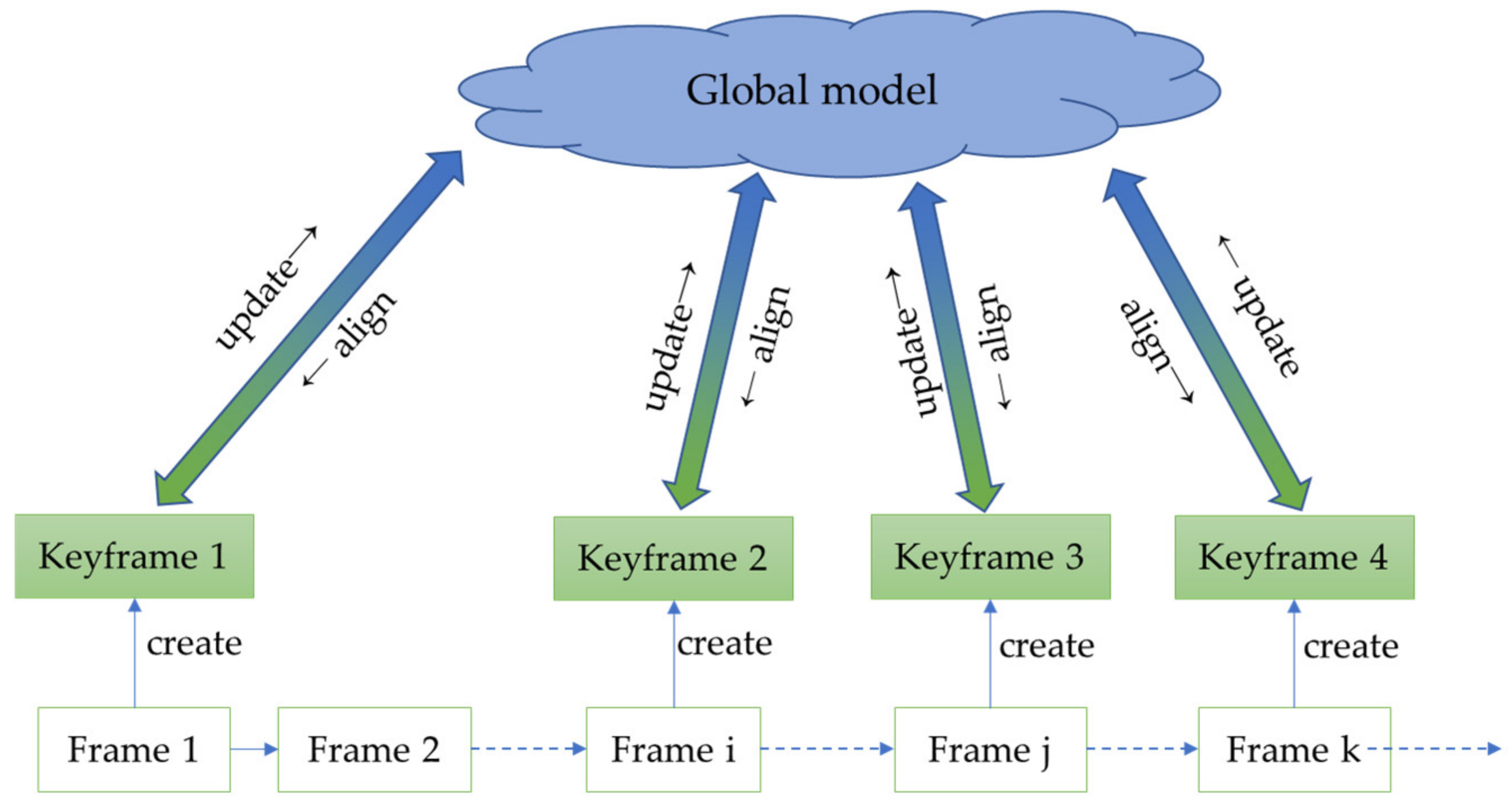
As shown in Figure 6, when the target moves for a few frames, we create a keyframe and align it with the augmented global model, and then update the model with the keyframe. Using a global model helps to reduce the accumulated errors in the pose estimation. Notably, the ordinary frames only participate in the frame-to-frame registration and do not participate in the global model updating, which reduces the amount of calculation of the pose-estimation system.
The selection criteria for keyframes are as follows
  • 20 frames have passed from the previous key frame;
  • The Euclidean distance between the current frame position and the previous key frame position is greater than a certain threshold T1;
  • The difference of Euler angles between current frame and the previous key frame is greater than a certain threshold T2.
Considering the data quality, three consecutive frames of data will be used for median filtering to ensure data accuracy when selecting key frames, so as to avoid the reduction of model accuracy caused by the error of single frame data.

2.4.2. Model Updating

In addition, a novel method to sparsify the point cloud of model was proposed, which avoids the linear growth of points in the global model, reduces both time and memory consumption. The proposed method aims to update the points of the global model point cloud P G with the points of the keyframe point cloud P K , under conditions of a known transformation matrix T k .
To determine the corresponding set of the two-point cloud, we use the image projection approach described in Section 2.1. instead of the improved registration algorithm mentioned above. We assume that they are from the same part of the non-cooperative target, and we merge the two points with their own intensity value as follows
P u , v G = I u , v G P u , v G + I u , v k P u , v k I u , v G + I u , v k i f P u , v G P u , v k 2 > T k P u , v k o t h e r w i s e
I u , v G = I u , v G + I u , v k
where P u , v G P u , v k 2 represents the Euclidean distance between the corresponding point pairs in the global model and keyframes. When the Euclidean distance of the corresponding point pair is less than the preset threshold T k , we consider it to be a measurement error; thus, we merge the two points. When the Euclidean distance of the corresponding point pair is greater than T, we consider that the position of the point has changed greatly and update the point P u , v G in the global model with the point P u , v k in the keyframe.

3. Semi-Physical Experiment and Analysis

In order to verify the performance of the proposed pose-estimation system for the non-cooperative target, ground semi-physical experiments were carried out.

3.1. Experimental Environment Setup

As shown in Figure 7a, a 1:1 satellite model was regarded as a non-cooperative target, and the motion of the non-cooperative target was simulated using the motion of the manipulator on the ABB (Asea Brown Boveri) robot arm.
The TOF camera was fixed on a Y-plate connected at the end of the robot arm to simulate the service spacecraft, as presented in Figure 7b, with the camera specifications shown in Table 3.
To verify the robustness of the proposed algorithm, we used the robot and satellite model to simulate the rotation and translation of the non-cooperative target in the laboratory, using the TOF camera to collect data, and comparing our method with other classic methods (ICP, GICP, and NDT).
In the experiment, we rotated the satellite model 720° around the flange of the robot arm to simulate the spin of the target in space and moved the TOF camera 1000 mm along Z axis of the camera coordinate system to simulate the approaching process.
All the mentioned algorithms were implemented on a PC (I7-7700 at 2.8 GHz, 8 GB RAM) with Visual Studio 2019. The programming language was C++ and the Point Cloud Library (PCL) is used.

3.2. Results of Semi-Physical Experiments

In this paper, we estimated the pose of the non-cooperative target in laboratory, but the background point cloud is also obtained by TOF camera. If no preprocessing is performed, it will become estimating the pose of dynamic target in a static environment, and the pose-estimation scheme will not be applicable and does not conform to the real situation of the space environment.
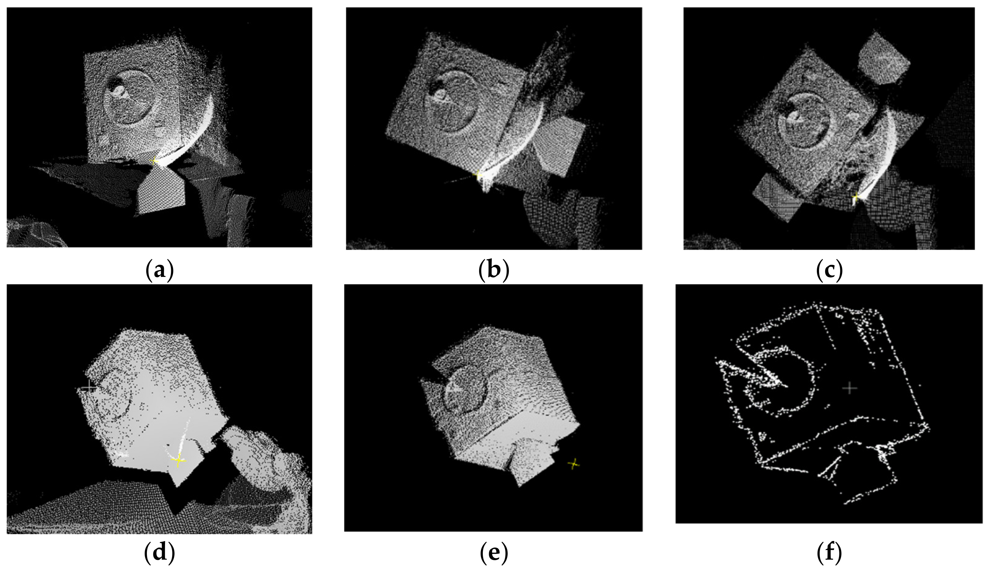
Figure 8a–c represent the raw data collected by the camera at different frames, and Figure 8d represents the raw data containing the target and the background at a certain moment. Figure 8e,f represent the process of noise reduction and salient point selection mentioned in Section 2.2. The input point cloud of all methods is presented in Figure 8e, which ensure that the comparisons are fair.
We calculated the relative pose of the target using Equation (9). The three-axis translations were denoted by the three components of translation vector t, and the three-axis rotation Euler angles needed to be decomposed by rotation matrix R via Equation (4).
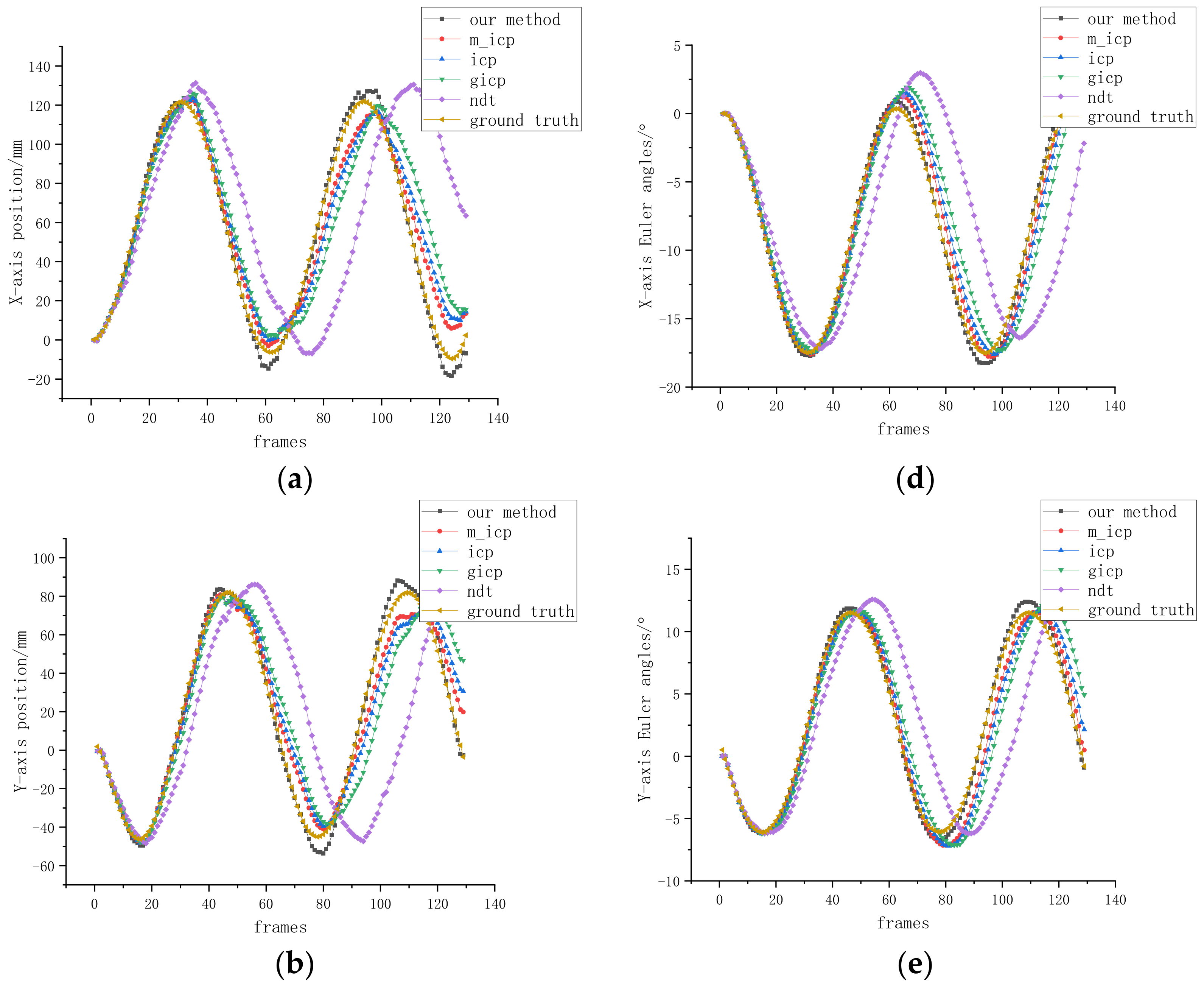
In this study, it was assumed that the rotation angles α, β, and γ around axis ZYX were denoted as roll, pitch, and yaw, respectively. In the experiments, we separately calculated the results of five methods (our method, m_icp (ICP modified in Section 2.3), original ICP, GICP, and NDT). The original ICP, GICP, and NDT inputs are all raw point clouds instead of filtered point clouds. The effectiveness and accuracy of our method could be determined by comparing these pose-estimation results with the ground truth.
In the rotation experiment, we fixed the TOF camera and rotated the target model 720° clockwise around the manipulator flange. Suppose the initial position of the target model is set to (0, 0, 0) mm, and the initial Euler angle is (0, 0, 0)°. However, because the installation positions of the target model and the TOF camera were not precisely adjusted, the Z axis of the camera was not parallel to the flange axis of the manipulator; therefore, the Euler angles of the other two axes were estimated to be non-zero in the rotation experiment.
Figure 9 presents our method estimation results and errors for the XYZ three-axis translation and Euler angles RPY during model motion. After 720° rotation of the target, the translation error of the three-axis XYZ was within 2 mm, and the Euler angle roll, pitch, and yaw errors of the three-axis YZX were within 0.5°.
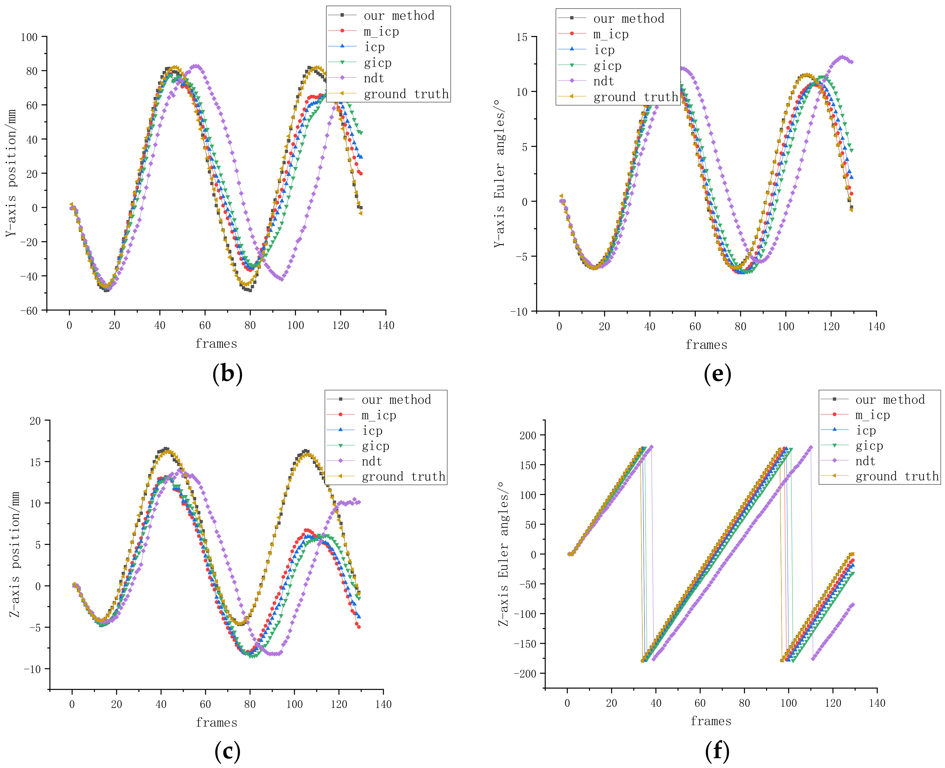
As shown in Figure 10, compared with other methods, the cumulative error of the results calculated by our method was the smallest. Among them, m_icp achieved smaller error than ICP, GICP, and NDT by picking salient points, rejecting incorrectly matched point pairs, and weighting the matched point pairs with intensity values. Only the frame-to-frame registration was performed, and the accumulated error was not eliminated; therefore, the XYZ axis translation error reached (20, 22, 5) mm after the 720° rotation, and the ZYX axis Euler angle RPY error reached (3, 2, 10)°. After introducing the key frame, the cumulative error is eliminated, the position error is less than 2 mm, and the angle error is less than 0.5°.
In the approaching experiment, we keep the satellite model in the same motion as the previous rotation experiment and move the camera 1000 mm in the positive direction of the Z axis. We supposed that the initial position of the target model was set to (0, 0, 0) mm and the initial Euler angle was (0, 0, 0)°.
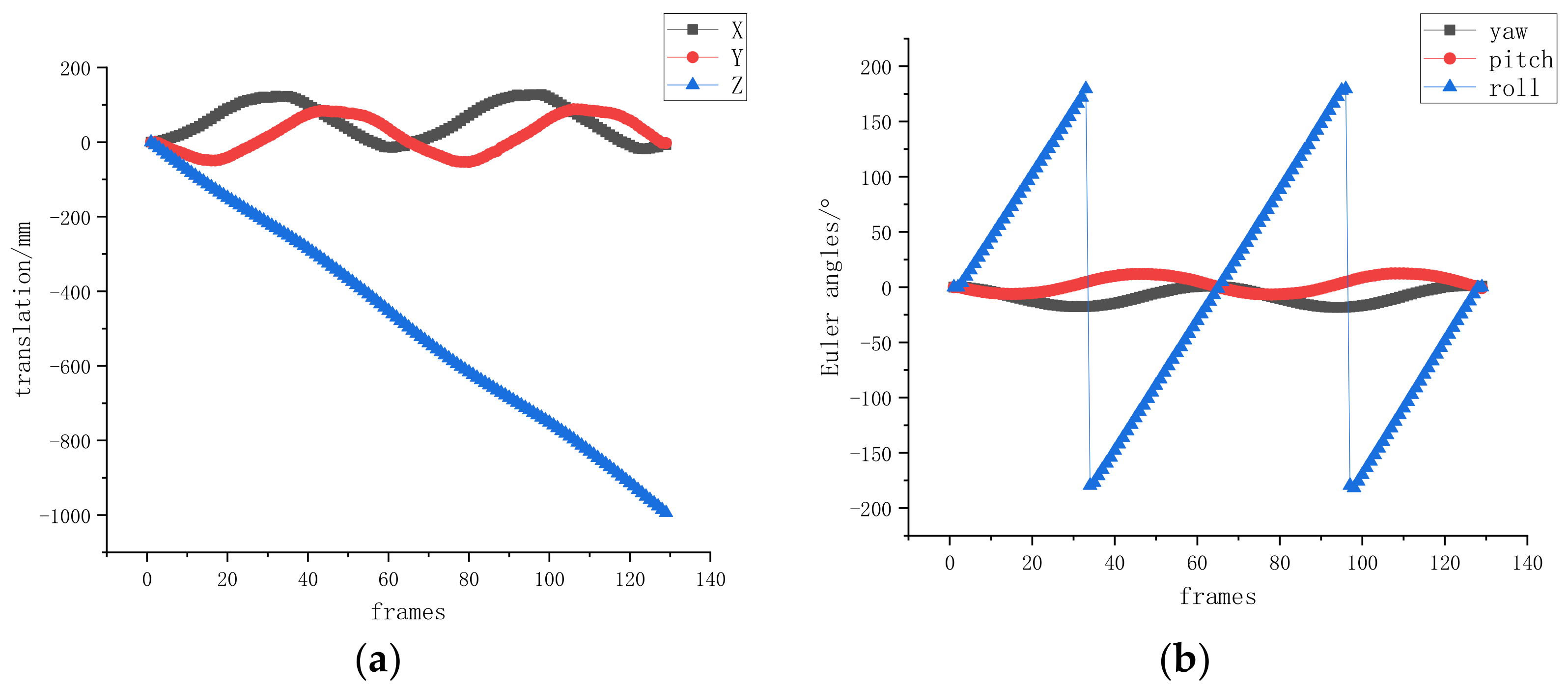
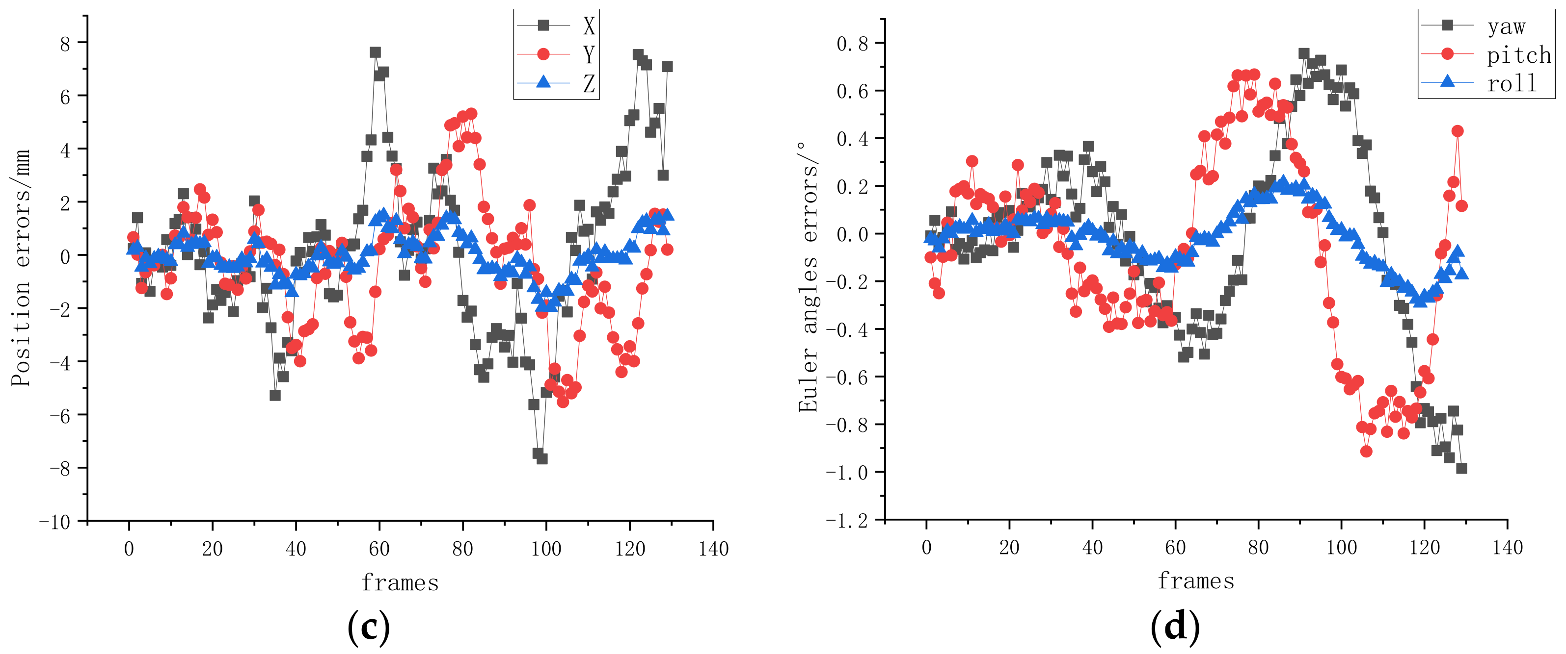
Figure 11 shows the method estimation results and errors of the three-axis translation and Euler angles of the target model during the TOF camera movement. The translation errors of the XYZ axes were within 8 mm, and the Euler angle yaw, pitch, and roll errors of the XYZ axes were within 1°.
As shown in Figure 12, our method had the smallest error among all indicators, as compared with other methods. There was almost no error in the Z-axis position results as estimated by various methods; the X-axis and Y-axis translation error was up to 5 mm.
The pose-estimation results of the rotation and translation experiments show that the pose-estimation accuracy of the proposed method is significantly better than other classical methods. Moreover, the accumulated errors of translation experiment are larger than single rotation experiment. In other words, when the target spins, the estimation result has almost no drift. When the camera approaches the target along the guide rail, the target becomes larger in the camera’s field of view, and the scale changes, resulting in a cumulative error. The proposed pose-estimation scheme can still achieve the high-precision (8 mm, 1°) pose estimation of non-cooperative targets and meet the requirements for aerospace applications. For the methods of other researchers [23,24,25,26,27,28,29,30,31,32], the prevailing positional accuracy is better than 10 mm and the angular accuracy is 2°. The reason for the greater accuracy improvement in this paper is that the geometric features of the target are extracted, and different error metrics are used for different features. The most important thing is that the key frame is used to reconstruct the target model.
In addition, as shown in Table 4, we also compared the amount of computation, and counted the time consumption as a representation of the amount of computation. It is worth noting that although preprocessing in the table belongs to our method, the data preprocessing part is included in each method to ensure that the data used by different methods are consistent.
As shown in Table 4, the total time consumed by our method is about 100 ms, and the tracking frequency can reach 10 Hz. By picking salient points and improving the error metric, we reduce the amount of computation to less than a tenth of the original.

4. Conclusions

In this paper, we have proposed a relative pose-estimation technique using a TOF camera for non-cooperative spacecraft in close-proximity operations. The proposed method significantly outperforms the workflow of other classical registration algorithms by picking salient points, using different error metrics for different points, rejecting incorrectly matched point pairs, and weighting the matched point pairs with intensity values, which ensures the accuracy of inter-frame alignment. In addition, three criteria are selected to create keyframes, and a novel method to sparsify the point cloud of model was proposed, which avoids the linear growth of points in the global model, reduces time consumption.
Then, we assembled the experimental platform to conduct semi-physical experiments. The results show that the modified ICP method has the smallest translation error and Euler angles error as compared with other classical methods (ICP, GICP, and NDT), and after introducing keyframes and global model, we eliminated the accumulated error. The cumulative error of translation was within 8 mm, and the cumulative error of the Euler angle was within 1 degree. The total time consumption is about 100 ms, and the pose tracking frequency can reach 10 Hz.
In future studies, we will conduct more experiments to verify the performance of our method. At the same time, we also hope to introduce a visible light camera for some cases where the target surface is relatively flat and cannot detect salient points, so as to improve the robustness of pose estimation.

Author Contributions

Conceptualization, D.S. and H.D.; Methodology, D.S.; Validation, D.S. and L.H.; Formal analysis, H.D.; Investigation, H.P.; Resources, H.P.; Data curation, D.S. and L.H.; Writing—Original draft, D.S.; Writing—Review & editing, L.H.; Supervision, H.D.; Funding acquisition, H.P. All authors have read and agreed to the published version of the manuscript.

Funding

This research was supported by the Preliminary Research Foundation of Equipment, grant number 3050404030 and the Innovation Program CX-325 of the Shanghai Institute of Technical Physics.

Conflicts of Interest

The authors declare no conflict of interest.

References

  1. Forshaw, J.L.; Aglietti, G.S.; Navarathinam, N.; Kadhem, H.; Salmon, T.; Pisseloup, A.; Joffre, E.; Chabot, T.; Retat, I.; Axthelm, R.; et al. RemoveDEBRIS: An in-orbit active debris removal demonstration mission. Acta Astronaut. 2016, 127, 448–463. [Google Scholar] [CrossRef] [Green Version]
  2. Zhao, P.Y.; Liu, J.G.; Wu, C.C. Survey on research and development of on-orbit active debris removal methods. Sci. China Technol. Sci. 2020, 63, 2188–2210. [Google Scholar] [CrossRef]
  3. Li, W.J.; Cheng, D.Y.; Liu, X.G.; Wang, Y.; Shi, W.; Tang, Z.; Gao, F.; Zeng, F.; Chai, H.; Luo, W.; et al. On-orbit service (OOS) of spacecraft: A review of engineering developments. Prog. Aerosp. Sci. 2019, 108, 32–120. [Google Scholar] [CrossRef]
  4. Flores-Abad, A.; Ma, O.; Pham, K.; Ulrich, S. A review of space robotics technologies for on-orbit servicing. Prog. Aerosp. Sci. 2014, 68, 1–26. [Google Scholar] [CrossRef] [Green Version]
  5. Long, A.M.; Richards, M.G.; Hastings, D.E. On-orbit servicing: A new value proposition for satellite design and operation. J. Spacecr. Rocket. 2007, 44, 964–976. [Google Scholar] [CrossRef] [Green Version]
  6. Hirzinger, G.; Landzettel, K.; Brunner, B.; Fischer, M.; Preusche, C.; Reintsema, D.; Albu-Schäffer, A.; Schreiber, G.; Steinmetz, B. DLR’s robotics technologies for on-orbit servicing. Adv. Robot. 2004, 18, 139–174. [Google Scholar] [CrossRef]
  7. De Carvalho, T.H.M.; Kingston, J. Establishing a framework to explore the Servicer-Client relationship in On-Orbit Servicing. Acta Astronaut. 2018, 153, 109–121. [Google Scholar] [CrossRef] [Green Version]
  8. Zou, T.; Wang, L.; Zhu, T.; Zhai, X. Non-cooperative Target Relative Navigation Method Based on Vortex Light, Vision and IMU Information. In Proceedings of the 2021 6th International Conference on Systems, Control and Communications (ICSCC), Chongqing, China, 15–17 October 2021; pp. 48–53. [Google Scholar]
  9. Du, X.; Liang, B.; Xu, W.; Qiu, Y. Pose measurement of large non-cooperative satellite based on collaborative cameras. Acta Astronaut. 2011, 68, 2047–2065. [Google Scholar] [CrossRef]
  10. Wang, B.; Li, S.; Mu, J.; Hao, X.; Zhu, W.; Hu, J. Research Advancements in Key Technologies for Space-Based Situational Awareness. Space: Sci. Technol. 2022, 2022, 9802793. [Google Scholar] [CrossRef]
  11. Min, J.; Yi, J.; Ma, Y.; Chen, S.; Zhang, H.; Wu, H.; Cao, S.; Mu, J. Recognizing and Measuring Satellite based on Monocular Vision under Complex Light Environment. In Proceedings of the 2020 IEEE International Conference on Artificial Intelligence and Computer Applications (ICAICA), Dalian, China, 27–29 June 2020; pp. 464–468. [Google Scholar]
  12. Volpe, R.; Palmerini, G.B.; Sabatini, M. A passive camera-based determination of a non-cooperative and unknown satellite’s pose and shape. Acta Astronaut. 2018, 151, 805–817. [Google Scholar] [CrossRef]
  13. Cassinis, L.P.; Fonod, R.; Gill, E. Review of the robustness and applicability of monocular pose estimation systems for relative navigation with an uncooperative spacecraft. Prog. Aerosp. Sci. 2019, 110, 100548. [Google Scholar]
  14. Perfetto, D.M.; Opromolla, R.; Grassi, M.; Schmitt, C. LIDAR-based model reconstruction for spacecraft pose determination. In Proceedings of the 2019 IEEE 5th International Workshop on Metrology for AeroSpace (MetroAeroSpace), Turin, Italy, 19–21 June 2019; pp. 1–6. [Google Scholar]
  15. Zhu, W.; She, Y.; Hu, J.; Wang, B.; Mu, J.; Li, S. A hybrid relative navigation algorithm for a large–scale free tumbling non–cooperative target. Acta Astronaut. 2022, 194, 114–125. [Google Scholar] [CrossRef]
  16. May, S.; Droeschel, D.; Holz, D.; Wiesen, C.; Fuchs, S. 3D pose estimation and mapping with time-of-flight cameras. In Proceedings of the International Conference on Intelligent Robots and Systems (IROS), 3D Mapping Workshop, Nice, France, 22–26 September 2008. [Google Scholar]
  17. Zhu, W.; Mu, J.; Shao, C.; Hu, J.; Wang, B.; Wen, Z.; Han, F.; Li, S. System Design for Pose Determination of Spacecraft Using Time-of-Flight Sensors. Space: Sci. Technol. 2022, 2022, 9763198. [Google Scholar] [CrossRef]
  18. Tzschichholz, T.; Boge, T.; Schilling, K. Relative pose estimation of satellites using PMD-/CCD-sensor data fusion. Acta Astronaut. 2015, 109, 25–33. [Google Scholar] [CrossRef]
  19. Liu, Y.; Zhang, S.; Zhao, X. Relative Pose Determination of Uncooperative Spacecraft Based on Circle Feature. Sensors 2021, 21, 8495. [Google Scholar] [CrossRef]
  20. Kawahito, S.; Halin, I.A.; Ushinaga, T.; Sawada, T.; Homma, M.; Maeda, Y. A CMOS time-of-flight range image sensor with gates-on-field-oxide structure. IEEE Sens. J. 2007, 7, 1578–1586. [Google Scholar] [CrossRef]
  21. Opromolla, R.; Fasano, G.; Rufino, G.; Grassi, M. A model-based 3D template matching technique for pose acquisition of an uncooperative space object. Sensors 2015, 15, 6360–6382. [Google Scholar] [CrossRef] [Green Version]
  22. Opromolla, R.; Fasano, G.; Rufino, G.; Grassi, M. Pose estimation for spacecraft relative navigation using model-based algorithms. IEEE Trans. Aerosp. Electron. Syst. 2017, 53, 431–447. [Google Scholar] [CrossRef]
  23. Martínez, H.G.; Giorgi, G.; Eissfeller, B. Pose estimation and tracking of non-cooperative rocket bodies using time-of-flight cameras. Acta Astronaut. 2017, 139, 165–175. [Google Scholar] [CrossRef]
  24. Zeng-yu, S.U.; Yue, G.A. Relative position and attitude measurement for non-cooperative spacecraft based on binocular vision. J. Astronaut. Metrol. Meas. 2017, 37, 1. [Google Scholar]
  25. Zhang, S.; Li, J.; Zhang, W.; Zhou, W. Research on docking ring pose estimation method based on point cloud grayscale image. Adv. Space Res. 2022, 70, 3466–3477. [Google Scholar] [CrossRef]
  26. Zhao, G.; Xu, S.; Bo, Y. LiDAR-based non-cooperative tumbling spacecraft pose tracking by fusing depth maps and point clouds. Sensors 2018, 18, 3432. [Google Scholar] [CrossRef] [PubMed]
  27. Wang, Q.; Lei, T.; Liu, X.; Cai, G.; Yang, Y.; Jiang, L.; Yu, Z. Pose estimation of non-cooperative target coated with MLI. IEEE Access 2019, 7, 153958–153968. [Google Scholar] [CrossRef]
  28. Kang, G.; Zhang, Q.; Wu, J.; Zhang, H. Pose estimation of a non-cooperative spacecraft without the detection and recognition of point cloud features. Acta Astronaut. 2021, 179, 569–580. [Google Scholar] [CrossRef]
  29. Liu, X.; Wang, H.; Chen, X.; Chen, W.; Xie, Z. Position Awareness Network for Non-Cooperative Spacecraft Pose Estimation Based on Point Cloud. IEEE Trans. Aerosp. Electron. Syst. 2022, 1–13. [Google Scholar] [CrossRef]
  30. Besl, P.J.; McKay, N.D. Method for registration of 3-D shapes. In Sensor Fusion IV: Control Paradigms and Data Structures; SPIE: Bellingham, DC, USA, 1992; Volume 1611, pp. 586–606. [Google Scholar]
  31. Segal, A.; Haehnel, D.; Thrun, S. Generalized-icp. In Robotics: Science and Systems; MIT Press: Cambridge, MA, USA, 2009; Volume 2, p. 435. [Google Scholar]
  32. Biber, P.; Straßer, W. The normal distributions transform: A new approach to laser scan matching. In Proceedings of the 2003 IEEE/RSJ International Conference on Intelligent Robots and Systems (IROS 2003), Las Vegas, NV, USA, 27–31 October 2003; Volume 3, pp. 2743–2748. [Google Scholar]
  33. Sabov, A.; Krüger, J. Identification and correction of flying pixels in range camera data. In Proceedings of the 24th Spring Conference on Computer Graphics, Budmerice Castle, Slovakia, 21–23 April 2008; pp. 135–142. [Google Scholar]
  34. Xiao, J.; Zhang, J.; Adler, B.; Zhang, H.; Zhang, J. Three-dimensional point cloud plane segmentation in both structured and unstructured environments. Robot. Auton. Syst. 2013, 61, 1641–1652. [Google Scholar] [CrossRef]
  35. Holzer, S.; Rusu, R.B.; Dixon, M.; Gedikli, S.; Navab, N. Adaptive neighborhood selection for real-time surface normal estimation from organized point cloud data using integral images. In Proceedings of the 2012 IEEE/RSJ International Conference on Intelligent Robots and Systems, Vilamoura-Algarve, Portugal, 7–12 October 2012; pp. 2684–2689. [Google Scholar]
  36. Borgefors, G. Distance transformations in digital images. Comput. Vis. Graph. Image Process. 1986, 34, 344–371. [Google Scholar] [CrossRef]
  37. Foix, S.; Alenya, G.; Torras, C. Lock-in time-of-flight (ToF) cameras: A survey. IEEE Sens. J. 2011, 11, 1917–1926. [Google Scholar] [CrossRef] [Green Version]
  38. Chen, S.; Chang, C.W.; Wen, C.Y. Perception in the dark; development of a tof visual inertial odometry system. Sensors 2020, 20, 1263. [Google Scholar] [CrossRef]
Figure 1. The pipeline of the proposed non-cooperative target pose-estimation system.
Remotesensing 14 06100 g001
Figure 2. Schematic diagram of the TOF camera calibration. (a) Near-infrared intensity image; (b) dot detection result.
Remotesensing 14 06100 g002
Figure 3. Schematic of flying pixels.
Remotesensing 14 06100 g003
Figure 4. Distribution of salient points.
Remotesensing 14 06100 g004
Figure 5. Error metric for edge points.
Remotesensing 14 06100 g005
Figure 6. Generation of keyframes and updating the global model.
Remotesensing 14 06100 g006
Figure 7. Experimental environment setup. (a) Non-cooperative satellite model; (b) TOF camera installed on the service spacecraft.
Remotesensing 14 06100 g007
Figure 8. Input data processing. (a) Frame i; (b) Frame j; (c) Frame k; (d) Raw data; (e) Noise reduction; (f) Salient point detection.
Remotesensing 14 06100 g008
Figure 9. Pose-estimation results of our method for the rotation experiment. (a) Translation of the XYZ axis; (b) Euler angle RPY of the YZX axis; (c) Position errors of the XYZ axis; (d) Euler angles error of the YZX axis.
Remotesensing 14 06100 g009
Figure 10. Comparison of pose-estimation results for the rotation experiment. (a) X-axis translation; (b) Y-axis translation; (c) Z-axis translation; (d) X-axis Euler angle; (e) Y-axis Euler angle; (f) X-axis Euler angle.
Remotesensing 14 06100 g010aRemotesensing 14 06100 g010b
Figure 11. Pose-estimation results of our method for the translation experiment. (a) Translation of the XYZ axis; (b) Euler angle RPY of the YZX axis; (c) Position errors of the XYZ axis; (d) Euler angles error of the YZX axis.
Remotesensing 14 06100 g011aRemotesensing 14 06100 g011b
Figure 12. Comparison of pose-estimation results for the translation experiment. (a) X-axis translation; (b) Y-axis translation; (c) Z-axis translation; (d) X-axis Euler angle; (e) Y-axis Euler angle; (f) X-axis Euler angle.
Remotesensing 14 06100 g012aRemotesensing 14 06100 g012b
Table 1. Intrinsic parameters of the TOF camera.
ParameterValue
( f x , f y ) (525.89, 525.89)
( c x , c y ) (319.10, 232.67)
Table 2. Average processing time of different filtering algorithms.
MethodOur MethodBilateral FilterFast Bilateral FilterGuided FilterFast Guided Filter
Time Consumption (ms)1786510231779
Table 3. Specifications of the TOF camera.
ParameterValue
Resolution640 × 480 px, 0.3 MP
Pixel Size10.0 µm (H) × 10.0 µm (V)
Illumination4 × VCSEL laser diodes, Class1, @ 850 nm
Lens Field of View69° × 51° (nominal)
Table 4. Comparison of amount of computation for different methods.
MethodOur MethodICPGICPNDT
Time
Consumption (ms)
PreprocessingSalient Point SelectionModified ICP
Mean2036499467881145
Std. Dev346876495
Publisher’s Note: MDPI stays neutral with regard to jurisdictional claims in published maps and institutional affiliations.