Technical Note

A Novel Jamming Method against SAR Using Nonlinear Frequency Modulation Waveform with Very High Sidelobes

1
National Key Laboratory of Microwave Imaging Technology, Aerospace Information Research Institute, Chinese Academy of Sciences, Beijing 100190, China
2
The Key Laboratory of Radar Imaging and Microwave Photonics, Ministry of Eduction, Nanjing University of Aeronautics and Astronautics, Nanjing 211106, China
*
Author to whom correspondence should be addressed.
Remote Sens. 2022, 14(21), 5370; https://doi.org/10.3390/rs14215370
Submission received: 19 August 2022 / Revised: 23 September 2022 / Accepted: 15 October 2022 / Published: 26 October 2022
(This article belongs to the Section Environmental Remote Sensing)

Abstract

:
Synthetic aperture radar (SAR) systems have the capacity for day-and-night and all-weather surveillance, which has become increasingly indispensable for military surveillance and global comprehensive environmental monitoring. With the development of the high-resolution SAR imaging technique, studies on SAR jamming have also received much interest. Traditional jamming methods are based on linear-frequency-modulated (LFM) signals, and this method can achieve high main-lobe jamming gain. However, its sidelobe jamming energy is very low. To solve this issue, a novel nonlinear frequency modulation (NLFM) waveform design method for SAR jamming is proposed in this paper. Compared with LFM waveforms, the designed waveforms have the same main-lobe jamming gain and very high sidelobes, which can significantly improve jamming performance. Moreover, detailed simulation experiments were carried out to verify the effectiveness of the newly proposed jamming scheme.

1. Introduction

Synthetic aperture radar (SAR) technology is developing rapidly, driven by the demands of military reconnaissance and the progression of signal-processing technology [1,2,3,4]. Compared with other radars, SAR has a large scale, and high resolution-imaging and target-recognition capabilities [5,6,7,8,9]. The above-mentioned capabilities have posed a great threat to reconnaissance targets. Therefore, it has become an important sensor for satellite-borne or airborne reconnaissance platforms, and plays a pivotal role in modern electronic warfare.
In order to better realize the concealment of important objects (e.g., tanks, warships, and military aircraft), and to cover the actions that need to be protected, it is necessary to implement effective jamming in SARs [10,11]. Common jamming methods can be divided into three types: (1) deceptive jamming, (2) ejecting jamming, and (3) suppressive jamming [12,13,14,15]. Deceptive jamming can produce deceptive effects of high-fidelity points, surfaces, or scenes, but it is highly dependent on the parameters of reconnaissance, and its algorithm requires large computational amounts and achieves poor real-time performance. Ejection jamming forms a jamming image that is the superposition of a real image and a false image. It requires the very strict configuration of the jammer platform and much jamming power. Suppressive jamming methods aim at transmitting a high-power jamming signal to submerge real target information, which worsens the ability of the SAR system to perceive the information of the target. However, since the accumulation time of a SAR signal is extremely long, an SAR system achieves high range and azimuth compression gain after pulse compression processing. Therefore, the required jamming power to destroy SAR detection with conventional jamming methods is very high, and it is difficult to design effective jamming equipment. Furthermore, traditional suppression jamming generally uses noncoherent jamming signals such as noise, continuous waves, or swept continuous waves to cover important areas that need to be protected [16]. However, such interference requires very high power, the area to be protected is usually in the order of square kilometers, and incoherent interference is less effective. Another common jamming suppression method is to retransmit a delayed signal, such as frequency offset or phase offset, when receiving an SAR signal of the other party. For example, the digital radio frequency memory (DRFM) system [17] can coherently and repeatedly receive and retransmit SAR signals and series of identical duplicate signals. However, the power required by this method is also very high because interference signals transmitted by the system are incoherent in the Doppler domain [18], even if the jamming signal can obtain a high-range compression gain. Therefore, the effect of interference is not perfect.
On the other hand, traditional SAR systems transmit a linear frequency modulation (LFM) waveform that aims at obtaining a high-range compression gain. Therefore, the jamming system also transmits a modulated LFM waveform, obtaining a high main-lobe jamming gain. However, the sidelobe energy of LFM waveforms is very low, and their sidelobe jamming performance is poor. Compared to LFM waveforms, nonlinear frequency modulation (NLFM) waveforms have high design freedom and can shape the instantaneous frequency function to construct the power spectral density (PSD) of signals [19].
The research topic of NLFM waveforms is generally focused on the low sidelobes and low cross-correlation energy (CCE). Well-known NLFM waveform generation methods are based on the principle of the stationary phase (POSP) [20,21,22], and these methods are associated with the PSD and the instantaneous chirp rate, constructing spectral content. However, all these methods using weighting function as a PSD template, e.g., hamming and Taylor weighting functions, leading to the penalty of the main lobe widening. To solve this problem, many studies focused on the optimization of NLFM waveforms. Bézier curve and generalized piece wise linear (PWL) functions were used to define the symmetry instantaneous frequency function in [23,24,25], respectively, and multiobjective goal attainment optimization methods were employed. Furthermore, an NLFM optimization scheme based on the augmented Lagrangian genetic algorithm (ALGA) was proposed in [19], which was further verified in a real SAR system. The optimized NLFM waveform could obtain lower sidelobes and higher resolutions, whereas the real-time generation of precise NLFM waveforms is still a technical challenge. In that respect, a real-time and high-precision generation algorithm for NLFM waveforms was presented in [26], and a high-precision NLFM signal generator was further developed and employed in an LT-1 spaceborne SAR system [27].
On the other hand, research on quasiorthogonal waveforms for SAR ambiguity suppression has received considerable attention [28,29]. The principle behind these methods leverages the low CCE of transmitted signals. The designed waveforms should also have low sidelobes to ensure satisfactory imaging performance. Furthermore, corresponding Tx and processing methods for single polarization and quadrature-polarimetric (quad-pol) SARs were presented in [30,31], respectively. Different from the above waveform design problems, this paper pays attention to the design of an NLFM waveform with very high sidelobes that aims at improving sidelobe jamming performance without the loss of the main-lobe jamming gain.
The rest of this paper is organized as follows. In Section 2, the coding model, correlation function, and optimization method are detailed. In Section 3, the comparative simulation experiments between the LFM waveforms and the proposed waveforms are provided to corroborate the theoretical developments. Lastly, conclusions are drawn in Section 4.

2. Design Method for NLFM Waveforms

The designed NLFM waveforms constructed with several LFM chirp subpulses are detailed in this section, and the instantaneous frequency function is shown in Figure 1.

2.1. Coding Model

According to Figure 1, the signal could be constructed with N 1 chirp subpulses:
s ¯ ( t ) = n = 1 N 1 s n ( t ( n 1 ) T s ) ,
where
s n ( t ) = rect t T s / 2 T s exp ( j π α n t 2 ) exp ( j 2 π b n t ) ,
with
rect t = 1 , 0.5 t 0.5 0 , elsewhere ,
where T s = T N 1 is the subpulse length, T is the total pulse length, α n is the FM slope, and b n is the offset of the nth subpulse. In addition,
α n = b n + 1 b n T s ,
where b n and b n + 1 are the starting and final instantaneous frequencies of the nth subpulse, respectively, n = 1 , , N 1 . Obviously, the constructed NLFM waveform depended on control point vector b = ( b 1 , b 2 , , b N ) and can be synthetically denoted with s ¯ ( t ; b ) .

2.2. Correlation Function

To further perform optimization processing, it was necessary to formulate the correlation functions of the proposed waveforms, and the autocorrelation function between s ¯ 1 ( t ; b 1 ) and s ¯ 2 ( t ; b 2 ) can be represented as follows.
g ( τ ; b 1 ; b 2 ) = s ¯ 1 ( t ; b 1 ) s ¯ 2 * ( t τ ; b 2 ) d t = n = 1 N 1 s 1 , n t ( n 1 ) T s × m = 1 N 1 s 2 , m * t ( m 1 ) T s τ d t = n = 1 N 1 m = 1 N 1 f n , m 1 , 2 ( τ ) ,
where s i , n t ( n 1 ) T s is the nth subpulse of s ¯ i ( t ; b i ) with n { 1 , , N 1 } and i { 1 , 2 } . In addition, f n , m 1 , 2 ( τ ) is the subpulse cross-correlation function given by
f n , m 1 , 2 ( τ ) = s 1 , n t ( n 1 ) T s s 2 , m * t ( m 1 ) T s τ d t .
Now, letting t = t ( n 1 ) T s and denoting by b i , n and α i , n , the instantaneous frequency offset and slope of the nth sub-pulse of the ith signal s ¯ i ( t ; b i ) , (6) can be reformulated as follows.
f n , m 1 , 2 ( τ ) = s 1 , n t s 2 , m * t + ( n m ) T s τ d t = exp j π α 2 , m τ 2 exp j 2 π b 2 , m + α 2 , m ( n m ) T s τ × exp j 2 π b 2 , m ( n m ) T s exp j π α 2 , m ( n m ) 2 T s 2 × rect t T s / 2 T s rect t + ( n m 1 / 2 ) T s τ T s × exp j π α 1 , n α 2 , m t 2 × exp j 2 π α 2 , m τ + b 1 , n b 2 , m α 2 , m ( n m ) T s t d t = exp j π α 2 , m τ 2 exp j 2 π b 1 , n Δ b n , m 1 , 2 τ Φ n , m 1 , 2 × rect τ ( n m ) T s 2 T s × t 1 t 2 exp j π Δ α n , m 1 , 2 t 2 exp j 2 π α 2 , m τ + Δ b n , m 1 , 2 t d t ,
where
Δ α n , m 1 , 2 = α 1 , n α 2 , m Δ b n , m 1 , 2 = b 1 , n b 2 , m α 2 , m ( n m ) T s Φ n , m 1 , 2 = exp j 2 π b 2 , m ( n m ) T s × exp j π α 2 , m ( n m ) 2 T s 2
and
t 1 = 0 and t 2 = ( 1 + m n ) T s + τ , if ( n m 1 ) T s < τ ( n m ) T s t 1 = τ + ( m n ) T s and t 2 = T s , if ( n m ) T s τ ( 1 + n m ) T s .
Now, different cases depending on the sign of Δ α n , m 1 , 2 must be analyzed. First, if Δ α n , m 1 , 2 > 0 , (7) can be expressed as follows.
f n , m 1 , 2 ( τ ) = exp j π α 2 , m + α 2 , m 2 Δ α n , m 1 , 2 τ 2 × exp j 2 π b 1 , n Δ b n , m 1 , 2 α 2 , m Δ b n , m 1 , 2 Δ α n , m 1 , 2 τ Φ n , m 1 , 2 × exp j π ( Δ b n , m 1 , 2 ) 2 Δ α n , m 1 , 2 rect τ ( n m ) T s 2 T s × t 1 t 2 exp j π Δ α n , m 1 , 2 t + α 2 , m τ + Δ b n , m 1 , 2 Δ α n , m 1 , 2 2 d t .
Hence, by indicating with
ξ ( t ) = Δ α n , m 1 , 2 t + α 2 , m + Δ b n , m 1 , 2 Δ α n , m 1 , 2
and performing the change in variable
ξ = Δ α n , m 1 , 2 t + α 2 , m + Δ b n , m 1 , 2 Δ α n , m 1 , 2 ,
(10) can be further simplified as follows.
f n , m 1 , 2 ( τ ) = exp j π α 2 , m + α 2 , m 2 Δ α n , m 1 , 2 τ 2 × exp j 2 π b 1 , n Δ b n , m 1 , 2 α 2 , m Δ b n , m 1 , 2 Δ α n , m 1 , 2 τ × Φ n , m 1 , 2 exp j π ( Δ b n , m 1 , 2 ) 2 Δ α n , m 1 , 2 Δ α n , m 1 , 2 rect τ ( n m ) T s 2 T s × ξ ( t 1 ) ξ ( t 2 ) exp j π ξ 2 d ξ = exp j π α 2 , m + α 2 , m 2 Δ α n , m 1 , 2 τ 2 × exp j 2 π b 1 , n Δ b n , m 1 , 2 α 2 , m Δ b n , m 1 , 2 Δ α n , m 1 , 2 τ × Φ n , m 1 , 2 exp j π ( Δ b n , m 1 , 2 ) 2 Δ α n , m 1 , 2 Δ α n , m 1 , 2 rect τ ( n m ) T s 2 T s × R ξ t 2 + j I ξ t 2 R ξ t 1 j I ξ t 1 .
In (13), R ( ξ ) and I ( ξ ) are the Fresnel integrals [32] given by
R ( ξ ) = 0 ξ cos π ξ 2 d ξ I ( ξ ) = 0 ξ sin π ξ 2 d ξ .
Then, if Δ α n , m 1 , 2 < 0 , (7) can be rewritten as follows.
f n , m 1 , 2 ( τ ) = exp j π α 2 , m + α 2 , m 2 Δ α n , m 1 , 2 τ 2 × exp j 2 π b 1 , n Δ b n , m 1 , 2 α 2 , m Δ b n , m 1 , 2 Δ α n , m 1 , 2 τ Φ n , m 1 , 2 × exp j π ( Δ b n , m 1 , 2 ) 2 Δ α n , m 1 , 2 rect τ ( n m ) T s 2 T s × t 1 t 2 exp j π Δ α n , m 1 , 2 t α 2 , m τ + Δ b n , m 1 , 2 Δ α n , m 1 , 2 2 d t .
Similarly, letting
ξ ( t ) = Δ α n , m 1 , 2 t α 2 , m + Δ b n , m 1 , 2 Δ α n , m 1 , 2
and performing the change in variable
ξ = Δ α n m 1 , 2 t α 2 , m + Δ b n , m 1 , 2 Δ α n , m 1 , 2 ,
(15) becomes
f n , m 1 , 2 ( τ ) = exp j π α 2 , m + α 2 , m 2 Δ α n , m 1 , 2 τ 2 × exp j 2 π b 1 , n Δ b n , m 1 , 2 α 2 , m Δ b n , m 1 , 2 Δ α n , m 1 , 2 τ × Φ n , m 1 , 2 exp j π ( Δ b n , m 1 , 2 ) 2 Δ α n , m 1 , 2 Δ α n , m 1 , 2 rect τ ( n m ) T s 2 T s × R ξ t 2 j I ξ t 2 R ξ t 1 + j I ξ t 1 .
Lastly, if Δ α n , m 1 , 2 = 0 , (7) can be reformulated as follows.
f n , m 1 , 2 ( τ ) = exp j π α 1 , n τ 2 exp j 2 π b 1 , n Δ b n , m 1 , 2 τ × Φ n , m 1 , 2 exp j π α 1 , n τ + Δ b n , m 1 , 2 T s + ( m n ) T s + τ × T s | τ + ( m n ) T s | rect τ ( n m ) T s 2 T s × sin c α 1 , n τ + Δ b n , m 1 , 2 T s | τ + ( m n ) T s | .

2.3. Optimization

In this subsection, to achieve better jamming performance, the waveform optimization problem is formulated and solved. As shown in Figure 2, the SAR system generated a LFM waveform on a baseband with bandwidth B and a pulse length T:
s LFM ( t ) = rect t T / 2 T exp j π k r t 2 ,
where k r is the chirp rate, as
k r = B T .
In addition, (20) could be recast by the proposed coding model:
s LFM ( t ) = s ¯ 1 ( t ; b 1 ) ,
with
b 1 , i = B 2 + B N 1 ( i 1 ) , i = 1 , 2 , , N ,
The transmitted radio frequency (RF) signal could be represented as follows:
s LFM , RF ( t ) = s ¯ 1 ( t ; b 1 ) exp 2 π f c t ,
where f c denotes the carrier frequency.
Then, the jamming system receives the transmitted SAR signal:
s R ( t ) = rect t t 0 T / 2 T exp j π k r ( t t 0 ) 2 × exp 2 π f c ( t t 0 ) = s ¯ 1 ( t t 0 ; b 1 ) exp 2 π f c ( t t 0 ) ,
where t 0 is the transmission time delay between the SAR system and jamming system. After receiving the SAR signal, the jamming system generates an RF NLFM waveform using the coding model presented in Section 2.1, which can be formulated as follows:
s T ( t ) = s ¯ 2 ( t t 0 t 1 ; b 2 ) exp 2 π f c ( t t 0 t 1 ) ;
where t 1 is the artificial time delay generated by the jamming system. After demodulation, the jamming signal on the baseband received by the SAR system can be formulated as follows:
s B ( t ) = s ¯ 2 ( t 2 t 0 t 1 ; b 2 ) exp 2 π f c ( 2 t 0 + t 1 ) .
Furthermore, the SAR system performs the range compression:
s RC ( τ 2 t 0 t 1 ) = exp 2 π f c ( 2 t 0 + t 1 ) × s ¯ 1 ( t ; b 1 ) s ¯ 2 * ( t ( τ 2 t 0 t 1 ) ; b 2 ) d t = exp 2 π f c ( 2 t 0 + t 1 ) g ( τ 2 t 0 t 1 ; b 1 ; b 2 ) .
Now, let us pay attention to the waveform design problem, which can be represented as the following constrained optimization.
P ( b 2 ) min b 2 f ISLR ( b 1 ; b 2 ) s . t . g ( 0 ; b 1 ; b 2 ) = C b 2 Ω ,
where
C = g ( 0 ; b 1 ; b 1 ) ,
and the constraint condition was set to ensure that the jamming signal could be well-focused, achieving the best jamming performance. In addition, f ISLR ( b 1 ; b 2 ) is the ISLR evaluation function between the two waveforms coded by b 1 and b 2 , which can be formulated as follows:
f ISLR ( b 1 ; b 2 ) = τ m T | g ( τ ; b 1 ; b 2 ) | 2 d τ 0 τ m | g ( 0 ; b 1 ; b 2 ) | 2 d τ ,
where interval [ τ m , τ m ] at the main-lobe temporal support with τ m generally depends on b 2 . Obviously, P ( b 2 ) is a nonconvex problem; to further simplify this problem, we could set that
s ¯ 2 ( t ; b 2 ) = F 1 | S ( f ; b 2 ) | exp j π f 2 k r ,
where S ( f ; b 2 ) is the Fourier transform of s ( t ; b 2 ) , and F 1 is the Fourier inversion operator. The optimization problem can thus be simplified as follows:
P ( b 2 ) min b 2 f ISLR ( b 1 ; b 2 ) s . t . b 2 Ω ,
and an efficient search method presented in [33] can be employed to solve it. Generally, the algorithm described in [33], called OptQuest/NLP or OQNLP, is a heuristic designed to find global optima for pure and mixed integer nonlinear problems with many constraints and variables where all problem functions are differentiable with respect to the continuous variables.

3. Simulations and Analysis

3.1. Point Target Simulation

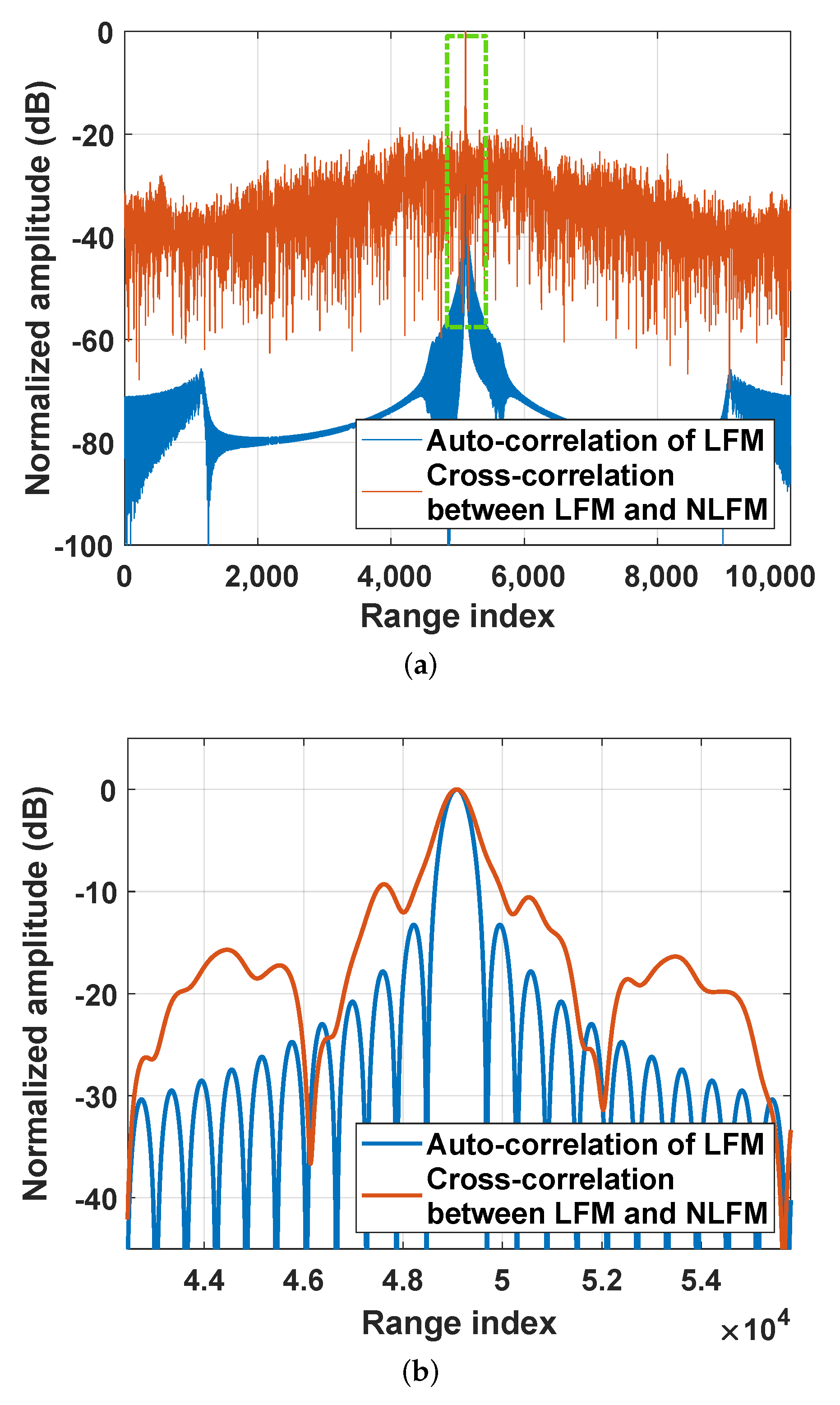
To demonstrate the jamming performance of the proposed waveform, pointlike target simulations and distributed scene simulations were carried out and are outlined in this section. Without loss of generality, the radar system works in strip-map mode, and the major system parameters (referencing the parameters of LT-1 spaceborne SAR system) are listed in Table 1. The enemy SAR was assumed to transmit conventional LFM signals while the proposed NLFM waveform was radiated by the jammer. The autocorrelation function of LFM, and the cross-correlation function between LFM and NLFM signals are shown in Figure 3a. Further, to clearly compare the waveform performance of LFM and the designed NLFM, the area marked with a rectangle in Figure 3a was enlarged and upsampled, and the processing result is shown in Figure 3b. Compared with LFM signals, the designed NLFM waveform showed a relatively high sidelobe level (the peak sidelobe ratio of the NLFM waveform was approximately 4 dB higher than that of the LFM waveform).
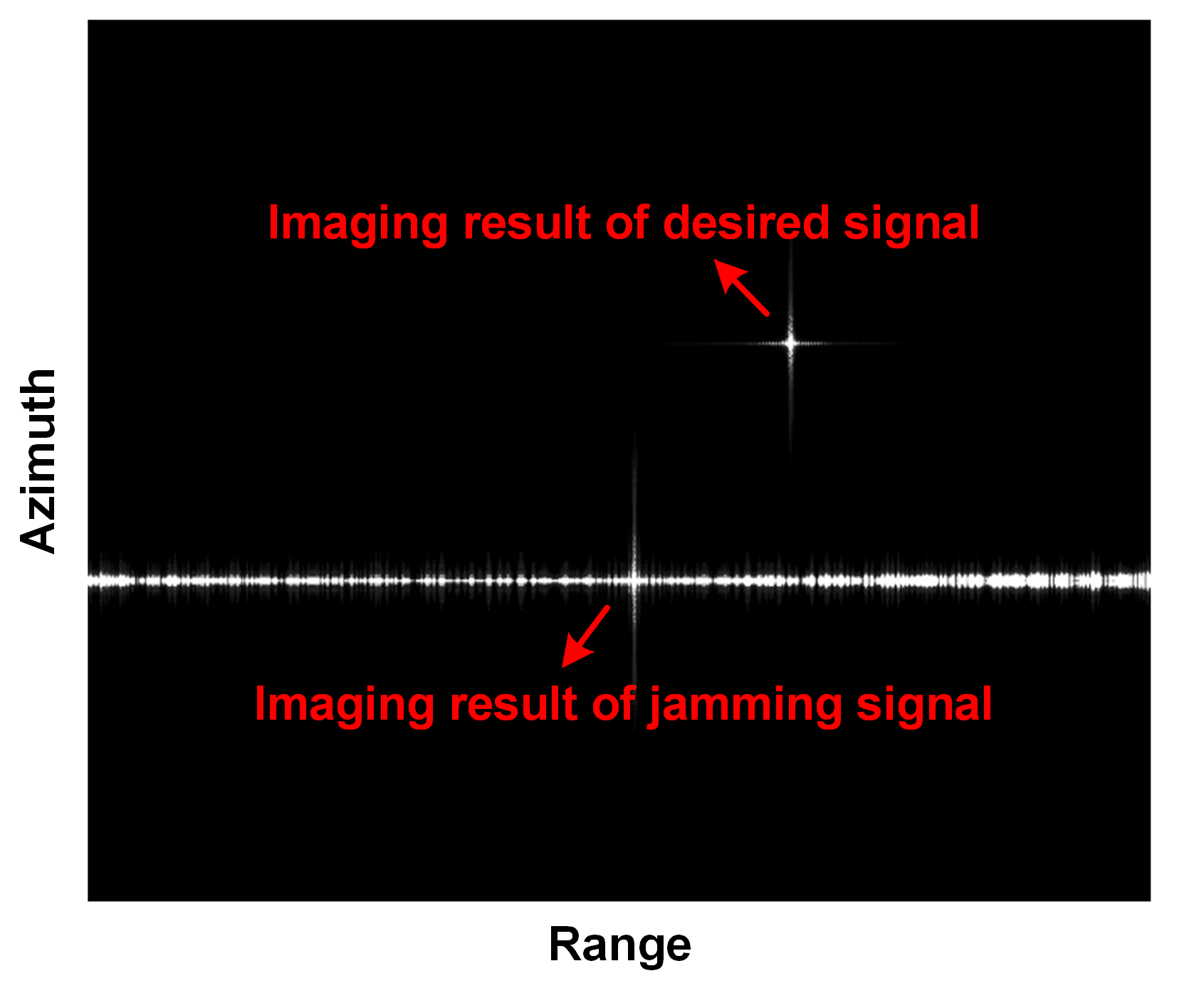
First, pointlike target simulations were implemented to better show the jamming performance of the proposed NLFM signal with a high sidelobe level. Two targets were illuminated by the LFM signal (transmitted by the energy SAR) and the NLFM signal (radiated by the jammer). The range-Doppler algorithm (RDA) was employed for the imaging processing of the recorded echoes (desired signal plus jamming signal); the imaging results of point targets are displayed in Figure 4. The jamming energy of the NLFM signal spreads over the range direction due to the high sidelobe. In particular, the designed NLFM waveform can only increase the sidelobe level in the range direction, while it has similar azimuth focusing performance with LFM waveform. Additionally, with the jamming signal generated by designed NLFM waveform, the range cells having the same azimuth position with the jamming signal can be well protected, which is not easy to achieve for LFM waveform.
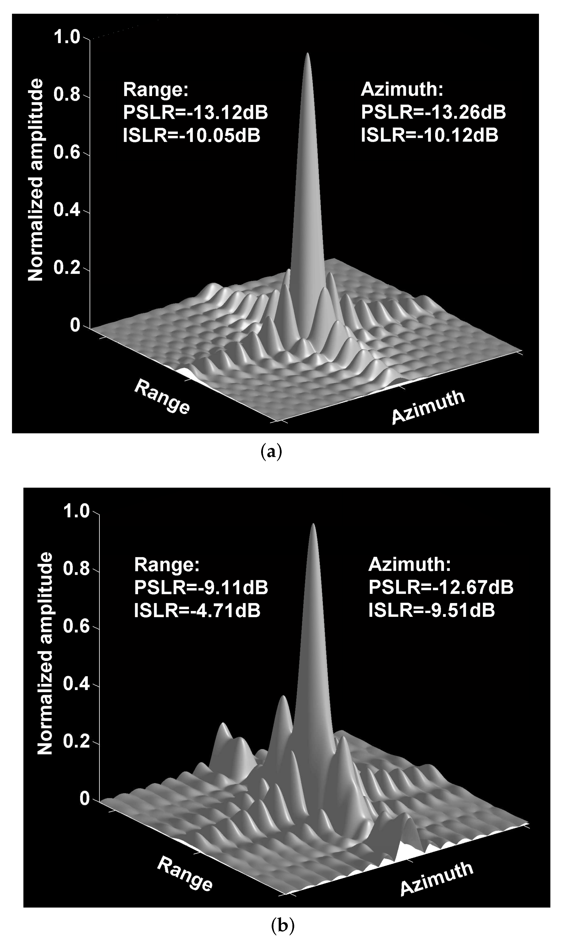
Afterwards, the target responses of the desired and jamming signals in Figure 4 are shown in Figure 5a,b, respectively. Without loss of generality, to quantitatively evaluate the focusing performance of Figure 5a,b, the peak sidelobe ratio (PSLR) and integrated sidelobe ratio (ISLR) [5] were calculated. It is evident that the pointlike target in Figure 5a was well-focused, while the focusing performance of Figure 5b deteriorated in the range direction. Compared to the current LFM waveform, the PSLR of the NLFM waveform deteriorated by 4.01 dB, and the ISLR was degraded by 5.34 dB. In barrage jamming, the high sidelobe characteristics of the designed NLFM signal were utilized to protect the regions of interest.

3.2. Distributed Scene Simulation

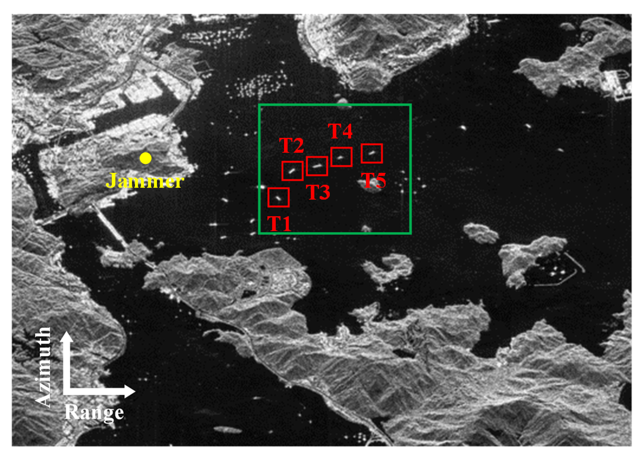
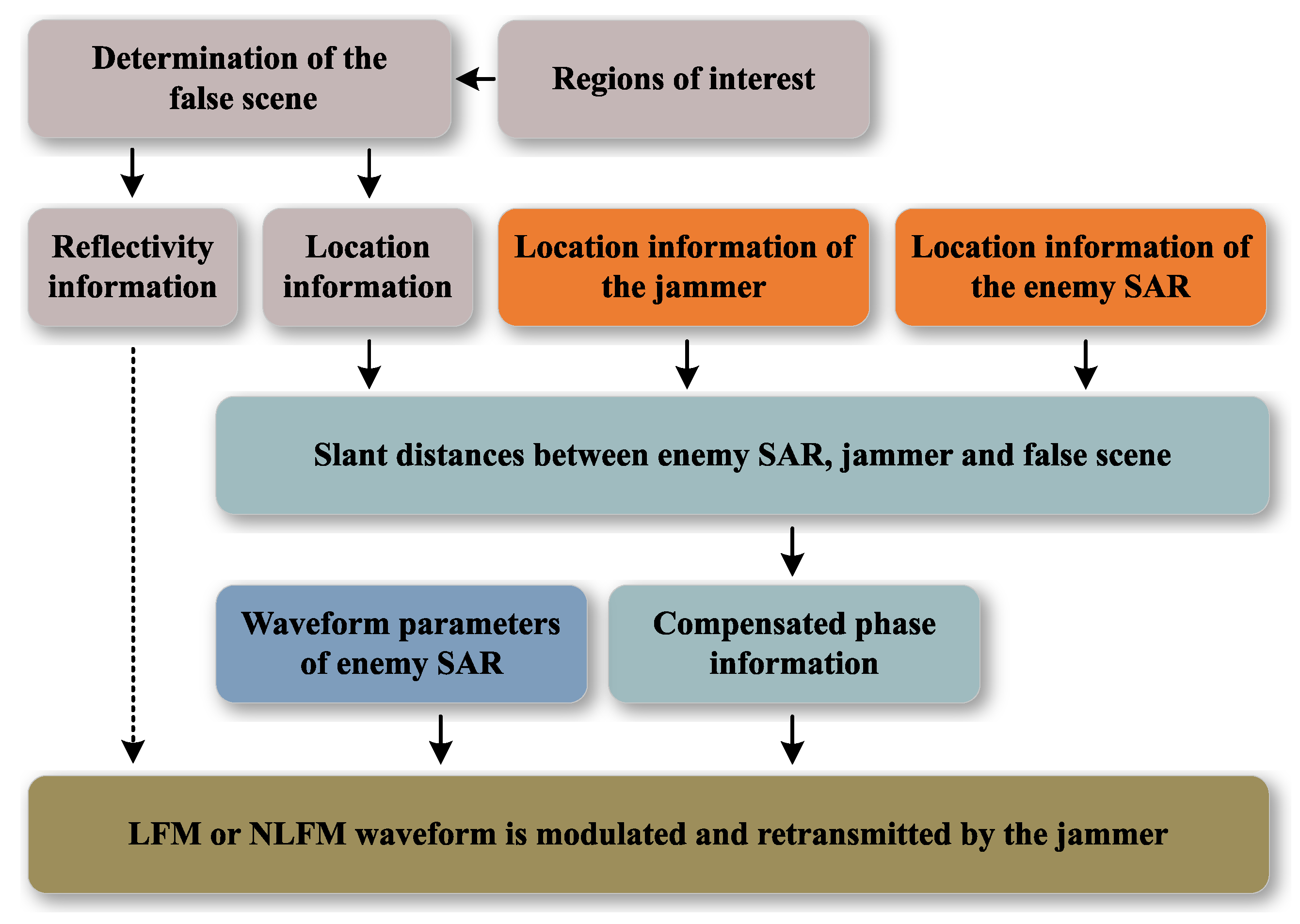
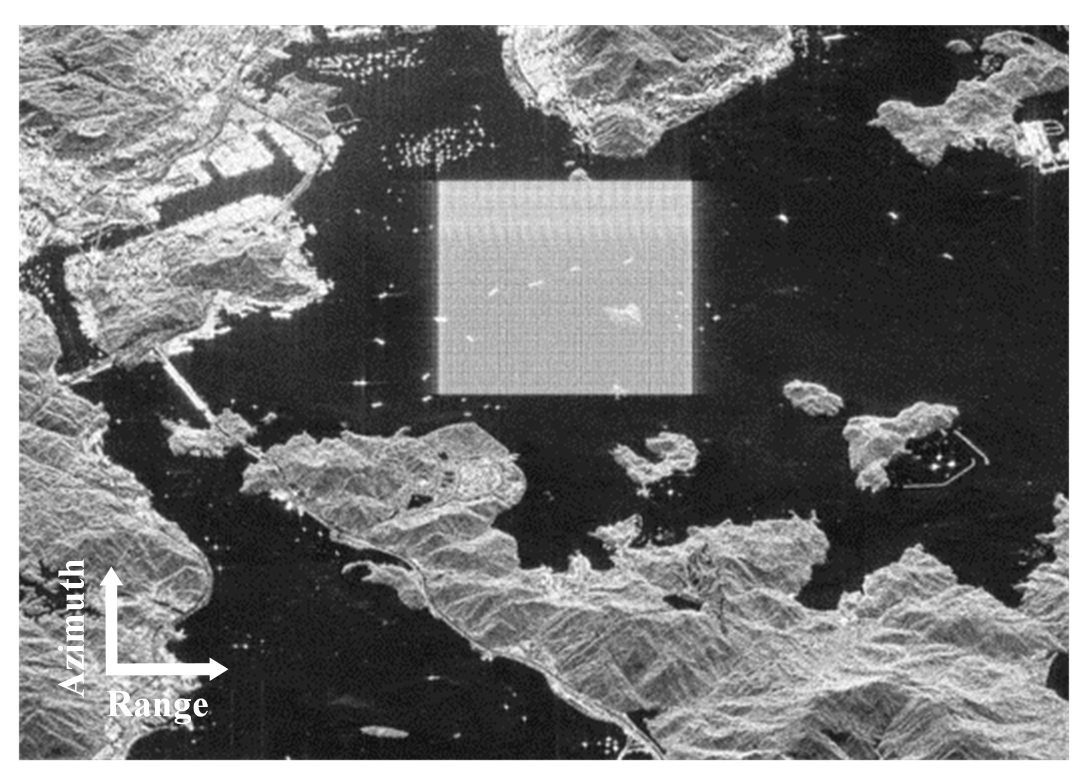
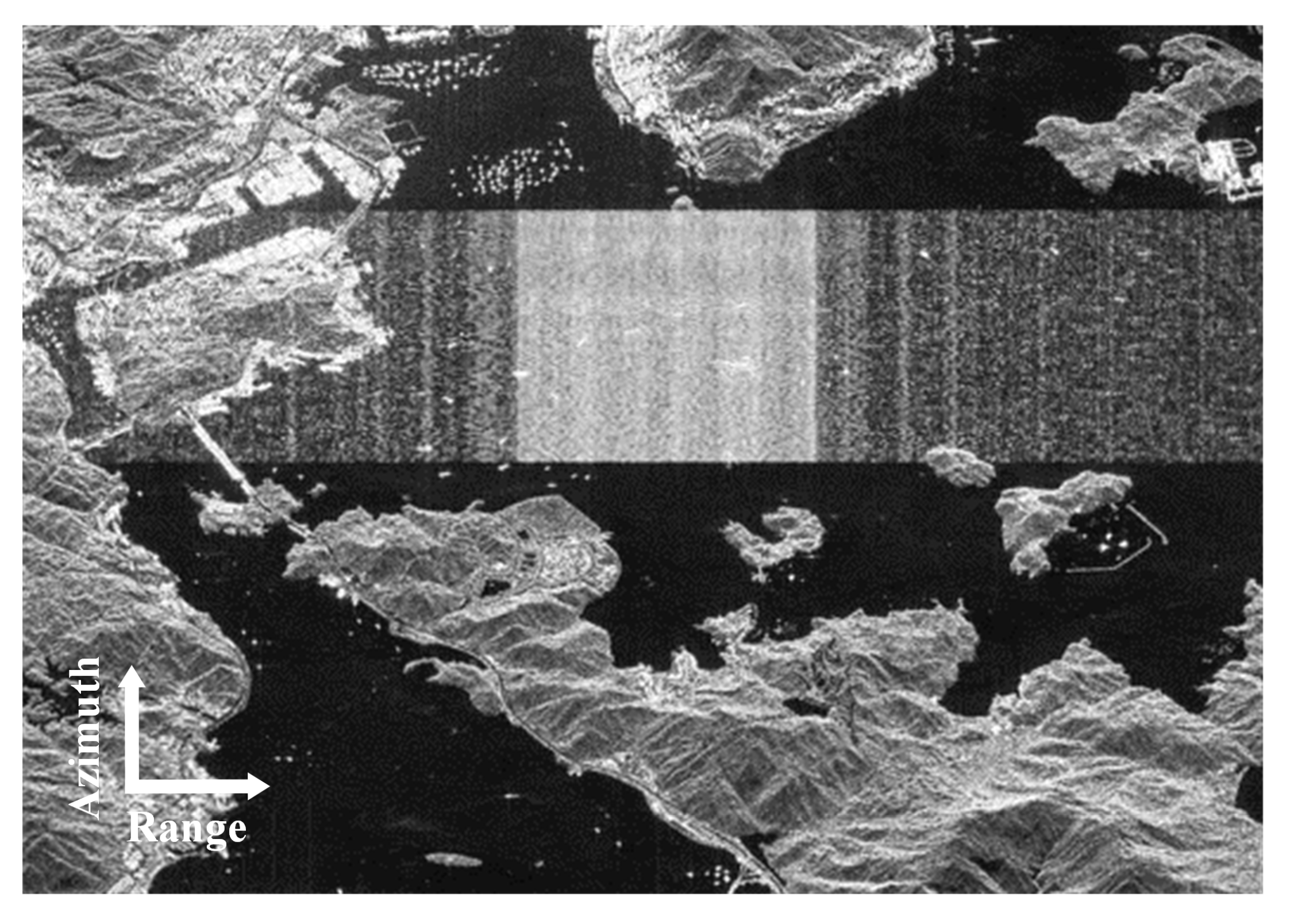
Lastly, to further evaluate the jamming performance of the designed NLFM signal, we conducted distributed target experiments on the basis of the same system parameters, as listed in Table 1. Figure 6 indicates the imaging scene illuminated by enemy SAR, and the five ships marked by red rectangles were set to be the targets of interest that needed to be protected by the jammer. Figure 7 illustrates the flowchart of jamming signal generation. Without loss of generality, the scatterers in the false scene had the same reflectivity information. To generate the jamming signals with accurate amplitude and location information, the LFM or NLFM jamming waveform needs to be modulated in the range frequency domain and retransmitted by the jammer. As shown in Figure 8 and Figure 9, one rectangular area was covered by the false scene. Particularly, Figure 8 and Figure 9 had the same jamming power. Comparing Figure 8 and Figure 9 shows that the targets of interest in Figure 9 were completely covered by the jamming signal. Additionally, by using the designed jamming waveform, a much broader area was influenced by the high sidelobe level.
Moreover, two metrics, i.e., contrast and entropy, were employed to quantitatively evaluate the jamming performance in Figure 8 and Figure 9. The image contrast is defined as follows [34]:
Contrast = ( u , v ) Q I ( u , v ) μ I 2 / ( N r · N a ) μ I μ I = ( u , v ) Q I ( u , v ) N r · N a , Q = ( u , v ) | 1 u N r , 1 v N a , u , v N ,
where I ( u , v ) refers to the image intensity in sampling unit ( u , v ) , and N r represents the number of range sampling units. In addition, the entropy can be calculated as follows:
Entropy = ( u , v ) Q D ( u , v ) ln D ( u , v ) , D ( u , v ) = I ( u , v ) / I s ,
where D ( u , v ) indicates the normalized image intensity, I s = ( u , v ) Q I ( u , v ) . Generally, higher contrast or lower entropy indicates better image quality. The contrast and entropy of the jamming area were calculated, and the results are listed in Table 2. The image acquired with the proposed method had lower contrast and higher entropy, indicating that the designed NLFM waveform achieved better jamming performance.

4. Conclusions

To ensure high range resolution, SAR systems generally transmit an LFM waveform; thus, to ensure a high jamming gain, a modulated LFM waveform is employed. However, the sidelobes of the LFM waveform after range compression atre very low, which means that sidelobe jamming performance is poor. This paper addressed a novel optimization framework of the NLFM waveform to obtain a waveform with very high sidelobes. The optimized waveform could greatly improve sidelobe jamming without the loss of the main-lobe jamming gain. At the analytical stage, detailed simulation experiments were carried out to illustrate the effectiveness of the devised signals and jamming scheme. Possible future studies might be focused on the implementation of the proposed waveform in a real SAR jamming system.

Author Contributions

Conceptualization, C.S.; methodology, C.S. and G.J.; validation, Y.W. (Yu Wang 1), P.L. and C.S.; formal analysis, L.Z. and B.W.; writing—original draft preparation, Y.W. (Yu Wang 2) and G.J.; writing—review and editing, Q.D. and Y.W. (Yirong Wu). All authors have read and agreed to the published version of the manuscript.

Funding

This work was supported in part by the National Key Laboratory Fund of Microwave Imaging Technology under grant E13D01011F, the National Natural Science Foundation of China under grant 62101248, the China Postdoctoral Science Foundation under grant 2022M711542, and the Natural Science Fund of Jiangsu Province under grant BK20210282.

Data Availability Statement

Not applicable.

Conflicts of Interest

The authors declare no conflict of interest.

Abbreviations

The following abbreviations are used in this paper:
SARSynthetic aperture radar
NLFMNonlinear frequency modulation
LFMLinear-frequency-modulated
Quad-PolQuadrature-polarimetric
DRFM      Digital radio frequency memory
PSDPower spectral density
POSPPrinciple of stationary phase
ALGAAugmented Lagrangian genetic algorithm
CCECross-correlation energy
PWLPiecewise linear

References

  1. Stimson, G.W. Introduction to Airborne Radar; SciTech Publishing, Inc.: Mendham, NJ, USA, 1998. [Google Scholar]
  2. Jin, G.; Deng, Y.; Wang, W.; Wang, R.; Zhang, Y.; Long, Y. Segmented Phase Code Waveforms: A Novel Radar Waveform for Spaceborne MIMO-SAR. IEEE Trans. Geosci. Remote Sens. 2021, 59, 5764–5779. [Google Scholar] [CrossRef]
  3. Wang, Y.; Zhu, D.; Jin, G.; Yu, Q.; Wang, P.; Niu, S.; Cheng, Y.; Wu, D. A Robust Digital Beamforming on Receive in Elevation for Airborne MIMO SAR System. IEEE Trans. Geosci. Remote. Sens. 2022, 60, 5233619. [Google Scholar] [CrossRef]
  4. Song, C.; Wu, Y.; Zhou, L.; Li, R.; Yang, J.; Liang, W.; Ding, C. A multicomponent micro-Doppler signal decomposition and parameter estimation method for target recognition. Sci. China Inf. Sci. 2019, 62, 29304. [Google Scholar] [CrossRef] [Green Version]
  5. Cumming, I.G.; Wong, F.H.C. Digital Processing of Synthetic Aperture Radar Data: Algorithms and Implementation; Artech House: Boston, MA, USA, 2005; pp. 473–476. [Google Scholar]
  6. Jin, G.; Deng, Y.; Wang, W.; Zhang, Y.; Liang, D.; Wang, R. A Novel Spaceborne MIMO-SAR Imaging Scheme Based on Improved OFDM Waveforms. IEEE Geosci. Remote Sens. Lett. 2021, 18, 2122–2126. [Google Scholar] [CrossRef]
  7. Ma, F.; Zhang, F.; Xiang, D.; Yin, Q.; Zhou, Y. Fast task-specific region merging for SAR image segmentation. IEEE Trans. Geosci. Remote Sens. 2022, 60, 5222316. [Google Scholar] [CrossRef]
  8. Yang, H.; Tao, M.; Chen, S.; Xi, F.; Liu, Z. On the Mutual Interference Between Spaceborne SARs: Modeling, Characterization, and Mitigation. IEEE Trans. Geosci. Remote Sens. 2021, 59, 8470–8485. [Google Scholar] [CrossRef]
  9. Yang, H.; Li, K.; Li, J.; Du, Y.; Yang, J. BSF: Block Subspace Filter for Removing Narrowband and Wideband Radio Interference Artifacts in Single-Look Complex SAR Images. IEEE Trans. Geosci. Remote Sens. 2022, 60, 5211916. [Google Scholar] [CrossRef]
  10. Wang, R.; Wang, X.; Cheng, S.; Meng, Y.; Zhang, G.; Zhou, Y. Plasma Passive Jamming for SAR Based on the Resonant Absorption Effect. IEEE Trans. Plasma Sci. 2018, 46, 928–933. [Google Scholar] [CrossRef]
  11. Ma, F.; Zhang, F.; Yin, Q.; Xiang, D.; Zhou, Y. Fast SAR image segmentation with deep task-specific superpixel sampling and soft graph convolution. IEEE Trans. Geosci. Remote Sens. 2021, 60, 5214116. [Google Scholar] [CrossRef]
  12. Sjögren, T.K.; Vu, V.T.; Pettersson, M.I.; Wang, F.; Murdin, D.J.G.; Gustavsson, A.; Ulander, L.M.H. Suppression of Clutter in Multichannel SAR GMTI. IEEE Trans. Geosci. Remote Sens. 2014, 52, 4005–4013. [Google Scholar] [CrossRef]
  13. Ender, J.; Berens, P.; Brenner, A.; Rossing, L.; Skupin, U. Multi-channel SAR/MTI system development at FGAN: From AER to PAMIR. In Proceedings of the IEEE International Geoscience and Remote Sensing Symposium, Toronto, ON, Canada, 24–28 June 2002; Volume 3, pp. 1697–1701. [Google Scholar] [CrossRef]
  14. Huang, L.; Dong, C.; Shen, Z.; Zhao, G. The Influence of Rebound Jamming on SAR GMTI. IEEE Geosci. Remote Sens. Lett. 2015, 12, 399–403. [Google Scholar] [CrossRef]
  15. Cheng, Y.; Zhu, D.; Jin, G.; Zhang, J.; Niu, S.; Wang, Y. A Novel Intrapulse Repeater Mainlobe-Jamming Suppression Method With MIMO-SAR. IEEE Geosci. Remote Sens. Lett. 2022, 19, 4507805. [Google Scholar] [CrossRef]
  16. Zhou, F.; Zhao, B.; Tao, M.; Bai, X.; Chen, B.; Sun, G. A Large Scene Deceptive Jamming Method for Space-Borne SAR. IEEE Trans. Geosci. Remote Sens. 2013, 51, 4486–4495. [Google Scholar] [CrossRef]
  17. Li, Z.; Xie, J.; Liu, W.; Zhang, H.; Xiang, H. Transmit Antenna Selection and Power Allocation for Joint Multi-Target Localization and Discrimination in MIMO Radar with Distributed Antennas under Deception Jamming. Remote Sens. 2022, 14, 3904. [Google Scholar] [CrossRef]
  18. Yang, K.; Ma, F.; Ran, D.; Ye, W.; Li, G. Fast Generation of Deceptive Jamming Signal Against Spaceborne SAR Based on Spatial Frequency Domain Interpolation. IEEE Trans. Geosci. Remote Sens. 2022, 60, 1–15. [Google Scholar] [CrossRef]
  19. Jin, G.; Deng, Y.; Wang, R.; Wang, W.; Wang, P.; Long, Y.; Zhang, Z.M.; Zhang, Y. An Advanced Nonlinear Frequency Modulation Waveform for Radar Imaging With Low Sidelobe. IEEE Trans. Geosci. Remote Sens. 2019, 57, 6155–6168. [Google Scholar] [CrossRef]
  20. Fowle, E. The design of FM pulse compression signals. IEEE Trans. Inf. Theory 1964, 10, 61–67. [Google Scholar] [CrossRef]
  21. de Buda, R. Stationary phase approximations of FM spectra. IEEE Trans. Inf. Theory 1966, 12, 305–311. [Google Scholar] [CrossRef]
  22. Vizitiu, I.; Anton, L.; Popescu, F.; Iubu, G. The synthesis of some NLFM laws using the stationary phase principle. In Proceedings of the 2012 10th International Symposium on Electronics and Telecommunications, Kuala Lumpur, Malaysia, 24–27 June 2012; pp. 377–380. [Google Scholar] [CrossRef]
  23. Kurdzo, J.M.; Cheong, B.L.; Palmer, R.D.; Zhang, G. Optimized NLFM pulse compression waveforms for high-sensitivity radar observations. In Proceedings of the 2014 International Radar Conference, Lille, France, 13–17 October 2014; pp. 1–6. [Google Scholar] [CrossRef]
  24. Luna, F.; Zavala, G.R.; Nebro, A.J.; Durillo, J.J.; Coello, C.A.C. Distributed Multi-Objective Metaheuristics for Real-World Structural Optimization Problems. Comput. J. 2016, 59, 777–792. [Google Scholar] [CrossRef]
  25. Saeedi, J.; Faez, K. Synthetic aperture radar imaging using nonlinear frequency modulation signal. IEEE Trans. Aerosp. Electron. Syst. 2016, 52, 99–110. [Google Scholar] [CrossRef]
  26. Jin, G.; Liu, K.; Deng, Y.; Sha, Y.; Wang, R.; Liu, D.; Wang, W.; Long, Y.; Zhang, Y. Nonlinear Frequency Modulation Signal Generator in LT-1. IEEE Geosci. Remote Sens. Lett. 2019, 16, 1570–1574. [Google Scholar] [CrossRef]
  27. Jin, G.; Liu, K.; Liu, D.; Liang, D.; Zhang, H.; Ou, N.; Zhang, Y.; Deng, Y.; Li, C.; Wang, R. An Advanced Phase Synchronization Scheme for LT-1. IEEE Trans. Geosci. Remote Sens. 2020, 58, 1735–1746. [Google Scholar] [CrossRef]
  28. Jin, G.; Deng, Y.; Wang, R.; Wang, W.; Zhang, Y.; Long, Y.; Liang, D. Mitigating Range Ambiguities With Advanced Nonlinear Frequency Modulation Waveform. IEEE Geosci. Remote Sens. Lett. 2019, 16, 1230–1234. [Google Scholar] [CrossRef]
  29. Bordoni, F.; Younis, M.; Krieger, G. Ambiguity Suppression by Azimuth Phase Coding in Multichannel SAR Systems. IEEE Trans. Geosci. Remote Sens. 2012, 50, 617–629. [Google Scholar] [CrossRef] [Green Version]
  30. Jin, G.; Zhu, D.; Yan, H.; Mao, X.; Deng, Y.; Wang, W.; Wang, R. New Insights Into SAR Alternate Transmitting Mode Based on Waveform Diversity. IEEE Trans. Geosci. Remote Sens. 2021, 1, 5209209. [Google Scholar] [CrossRef]
  31. Jin, G.; Aubry, A.; De Maio, A.; Wang, R.; Wang, W. Quasi-Orthogonal Waveforms for Ambiguity Suppression in Spaceborne Quad-Pol SAR. IEEE Trans. Geosci. Remote. Sens. 2021, 60, 5204617. [Google Scholar] [CrossRef]
  32. Boersma, J. Computation of Fresnel integrals. Math. Comput. 1960, 14, 380. [Google Scholar] [CrossRef]
  33. Ugray, Z.; Lasdon, L.; Plummer, J.; Glover, F.; Kelly, J.; Martí, R. Scatter search and local NLP solvers: A multistart framework for global optimization. INFORMS J. Comput. 2007, 19, 328–340. [Google Scholar] [CrossRef]
  34. Wang, Y.; Zhu, D.; Jin, G.; Niu, S.; Wang, X.; Cheng, Y.; Wu, D. Improved DBF-MIMO-SAR Waveform Transmission Scheme for Reducing the Cost of DOF in the Elevation. IEEE Trans. Aerosp. Electron. Syst. 2022, 1–15. [Google Scholar] [CrossRef]
Figure 1. Illustration of the instantaneous frequency history.
Remotesensing 14 05370 g001
Figure 2. Imaging result of point targets.
Remotesensing 14 05370 g002
Figure 3. Comparison between LFM waveform and the designed NLFM waveform. (a) Autocorrelation and cross−correlation functions; (b) enlarging and upsampling result of the area marked by the rectangle in (a).
Remotesensing 14 05370 g003
Figure 4. Imaging result of point targets.
Remotesensing 14 05370 g004
Figure 5. Imaging results of jamming and desired signals with respect to pointlike targets. (a) Target response of desired signal; (b) target response of jamming signal.
Remotesensing 14 05370 g005
Figure 6. Ground truth.
Remotesensing 14 05370 g006
Figure 7. Flowchart of barrage jamming.
Remotesensing 14 05370 g007
Figure 8. Jamming result of the LFM waveform.
Remotesensing 14 05370 g008
Figure 9. Jamming result of the designed NLFM waveform.
Remotesensing 14 05370 g009
Table 1. Spaceborne SAR simulation parameters.
ParametersValue
Orbit height607 Km
Center frequency1.26 GHz
SAR pulse width80 μ s
Bandwidth60 MHz
Sampling rate72 MHz
PRF3320 Hz
Antenna typePlanar
Antenna length in azimuth10
Antenna length in elevation5
Look angle25
Table 2. Contrast and entropy to evaluate jamming performance.
Figure 6Figure 8Figure 9
Contrast9.0462.4581.653
Entropy10.66711.44712.067
Publisher’s Note: MDPI stays neutral with regard to jurisdictional claims in published maps and institutional affiliations.