1. Introduction
One of the practically important fields for the deployment of unmanned underwater vehicles (UUV) is inspection of objects of the industrial subsea infrastructure, such as pipelines, communications, mining systems, etc. Today, well-proven remotely operated underwater vehicles (ROVs) are used for these purposes. However, the application of ROVs is associated with the use of bulky auxiliary equipment, which is inconvenient, expensive, and in some cases it limits the capabilities of these vehicles. Therefore, alternative technologies associated with the use of autonomous underwater vehicles (AUV) are being developed. The on-board computer allows for processing of the received data to make decisions related to inspection operations, and the absence of a tether makes the use of AUVs in some cases simply indispensable. An overview of the Subsea Infrastructure Inspection issue and considerations on the necessity to develop novel technologies based on AUV used today are provided in [
1,
2,
3,
4,
5]. A successful inspection mission requires high accuracy of AUV navigation relative to the objects being inspected, which is necessary for a detailed examination of specified elements on these structures. In this regard, substantial attention is paid to addressing the problem of precision navigation in the subsea environment. For this, various technologies with different types of sensors are used. Navigation technologies for AUV are usually based on inertial navigation systems combined with auxiliary sensors or other techniques, such as a Doppler velocity log (DVL), compass, pressure sensor, single/net fixed beacon, global positioning system (GPS), acoustic positioning system (APS), or geophysical navigation system, including optical cameras and imaging sonar (techniques that use external environmental information as references for navigation) [
6]. Some examples of the designs of different navigation technologies for AUV, including combinations of different types of sensors, different algorithms for processing hydro acoustic and optical images and having different applications are considered below.
Technologies based on the processing of sonar images including laser scanning data. Technologies for obtaining information about the external environment based on the use of acoustic images, laser scanning data, as well as options for joint processing of this in-formation are widely presented in the literature. For example, acoustic image processing is applied during automatic port inspections using AUVs [
7,
8]. A loop closure detector addressed to the simultaneous localization and mapping (SLAM) problem at semistructured environments using acoustic images acquired by forward-looking sonars was proposed in [
9]. A novel octree-based 3D exploration algorithm for AUVs to explore unknown underwater scenes in close proximity to the environment is proposed [
10]. The algorithm is based on data from a hydroacoustic sensor and an optical camera. Experimental results using a 3D underwater laser scanner mounted on an AUV for simultaneous localization and re-al-time mapping are presented in paper [
11]. The position of the robot is estimated using an extended Kalman filter, which combines data from the AUV navigation sensors. An overview of recent advances in integrated navigation technologies for AUVs and a guide for researchers who intend to use AUVs for autonomous monitoring of aquaculture is presented in [
12].
Technologies based on the processing of video mono and stereo images using visual odometry. In recent years, navigation technologies with video information processing for underwater applications have been actively developed, aimed at overcoming the negative effects characteristic of the underwater environment: lack of navigation using GPS and bottom relief maps, insufficient illumination, water turbidity, and the effect of currents.
The algorithms for tracking objects and calculating the AUV trajectory from a sequence of mono and stereo images, including the results of experiments in port conditions, are pre-sented in works [
13,
14,
15,
16]. Various visual odometry solutions for use in AUVs have been tested in a study [
17]. In particular, scale invariant feature transform (SIFT) [
18] and speeded up robust feature (SURF) [
19] detectors were compared as regards their efficiency in calculating vehicle movement.
Methods for underwater place recognition based on video information processing are known in the literature as a solution to the “loop closing problem”. They are used to neutralize the accumulated error of the SLAM algorithm. It implies that the accuracy of AUV navigation can be improved by taking into account repeated visits to the same places. To address it [
20], a method was proposed referred to as BoW (bag-of-words). This method is also applicable in our case when it comes to periodic AUV inspections of underwater industrial structures compactly located on an area of 200 × 300 m. It was further developed in a number of works [
21,
22,
23,
24,
25,
26,
27], where ideas were put forward for using visual stereo-odometry, a position graph, “loop closing” identification algorithms, anchor nodes for working in multisession mode, and an image classification with the Fisher vector, a vector of localized aggregated descriptors. The AUV localization technology based on the recognition of artificial markers placed on the bottom or on objects is also popular. For example, a method that uses visual measurements of underwater structures and arti-ficial landmarks is proposed in [
28]. The AUV localization method using ArUco markers placed on the bottom or on objects (cyclic coding) is considered in [
29].
The use of artificial neural networks. An AMB-SLAM online navigation algorithm based on artificial neural network was pro-posed in [
30]. The algorithm is based on the utilization of measurements made from the randomly distributed beacons of low-frequency magnetic fields, in addition to a single fixed acoustic beacon, on the featureless seafloor. Image representation for visual loop closure detection based on convolutional neural network [
31] is an image descriptor that can extract semantic information from an image and provide a high degree of invariance property.
Underwater sensor networks. Underwater sensor networks, known as Underwater Wireless Sensor Networks (UWSN), which are designed to perform remote monitoring of underwater objects and processes are described in [
32,
33]. Deployment of these gadgets is done in targeted acoustic zones for the collection of data and monitoring tasks. A detailed survey of localization technique for elements of the Underwater Acoustic Sensor Network (UASN) is given in [
34,
35]. However, the proposed techniques are focused on a single localization of network elements. In addition, they are time-consuming, and the requirements for localization accuracy are much less than those required when surveying objects.
Underwater localization acoustic based approach. Currently, acoustic positioning systems of various types are often used to support the localization of underwater vehicles and divers. The possible configurations of a localization system [
36] includes Long Baseline (LBL), Short Baseline (SBL), and Ultra Short Baseline (USBL) acoustic positioning systems. In the LBL case, a set of acoustic transponders is pre-deployed on the seafloor around the boundaries of the area of interest and the distance among transponders is typically hundreds of meters. LBL systems measure the AUV coordinates within the transponder base with constant accuracy. However, the coordinate measurement error is tens of centimeters and meters, which is unacceptable for our case. SBL base [
37] or USBL transceivers can be permanently deployed on the seafloor or float on the water surface. However, in both cases, the accuracy of the coordinate’s measurement decreases with the increasing distance between the AUV and the transceiver. At a distance of several hundred meters, the error can also be tens of centimeters and meters.
Other new approaches. Simulation of the behavior of a swarm of underwater drones (AUV) describes the study [
38] and the standoff tracking control of underwater glider to moving targets is described in [
39,
40]. It should, however, be noted that many of the above-mentioned methods bear some disadvantages: some of these have increased needs in computing resources (which are not always available on board an AUV), others require training neural networks, while most are designed for urban scenes or an indoor environment. Therefore, the development of methods to address the “loop closure problem” remains a highly relevant goal with respect to underwater scenes where GPS cannot be used, where no pre-built maps and accurate coordinate information about location of the objects being inspected are available in many cases, and the acoustic positioning systems used do not provide sufficient accuracy for inspection. These problems even increase as the depth of the inspected structure’s position grows.
However, in all of the above studies, the problem of calculating the AUV trajectory directly in the coordinate space of a local underwater object is not solved, and insufficient attention is paid to the use of 3D data obtained as a result of a video image. In particular, the use of spatial coordinates makes it possible to efficiently perform object recognition and AUV coordination relative to objects. As for the methods for recognizing underwater places and using artificial neural networks, they remain quite computationally laborious or require preliminary preparation.
In general, analysis of the above works has shown that the potential of video information is not fully implemented in most modern AUV navigation systems. It should also be noted that the growing demands for high-precision AUV navigation in terms of practical applications necessitate further research in this field.
An important requirement to methods designed is also the high operating speed, which is necessary for providing the opportunity to use them in real time mode. The study [
41] describes a technique for visual navigation using stereo imagery with the option of 3D reconstruction of objects in the subsea environment. This technique of navigation was used by the authors in the following works [
42,
43,
44]. A technology for referencing the AUV coordinates to a subsea object, based on the use of a preset 3D point model of the object and the application of the structural coherence criterion when comparing 3D points of the object with the model, is proposed in [
42]. This technology was developed to reduce computational costs by using a limited number of characteristic points with known absolute coordinates [
43]. Interesting results were obtained when tracking an underwater pipeline based on the integration of two sensors: a stereo video camera and a laser line [
44].
In the present article, we provide a new approach to addressing the issue of accurate AUV navigation using video information in the of a subsea production system (SPS) coordinate space when performing inspection missions.
The approach is based on the integrated use of the proposed virtual coordinate reference network of AUV to objects of the subsea production system and also the visual navigation method and the underwater object recognition method that we previously developed.
The proposed technology is aimed at improving the accuracy of calculation of the AUV localization with respect to the underwater objects being inspected, while minimizing computational costs.
The present paper is structured as follows. In
Section 2, the problem is formulated and a general approach to its solution is described.
Section 3.1 shows forming a virtual coordinate reference network. In
Section 3.2, referencing of the AUV to reference points during a working mission is described.
Section 3.3 and
Section 3.4 describe calculation of the AUV inspection trajectory using a virtual coordinate referencing net. In particular, the algorithm for calculating the AUV trajectory in the SPS coordinate space is described with an example of its use.
Section 4 shows experimentation to evaluate the efficiency of the approach proposed.
Section 5 presents a discussion.
Section 6 briefly describes the essence of the study conducted and specifies its further development.
2. Problem Statement: Description of the General Approach
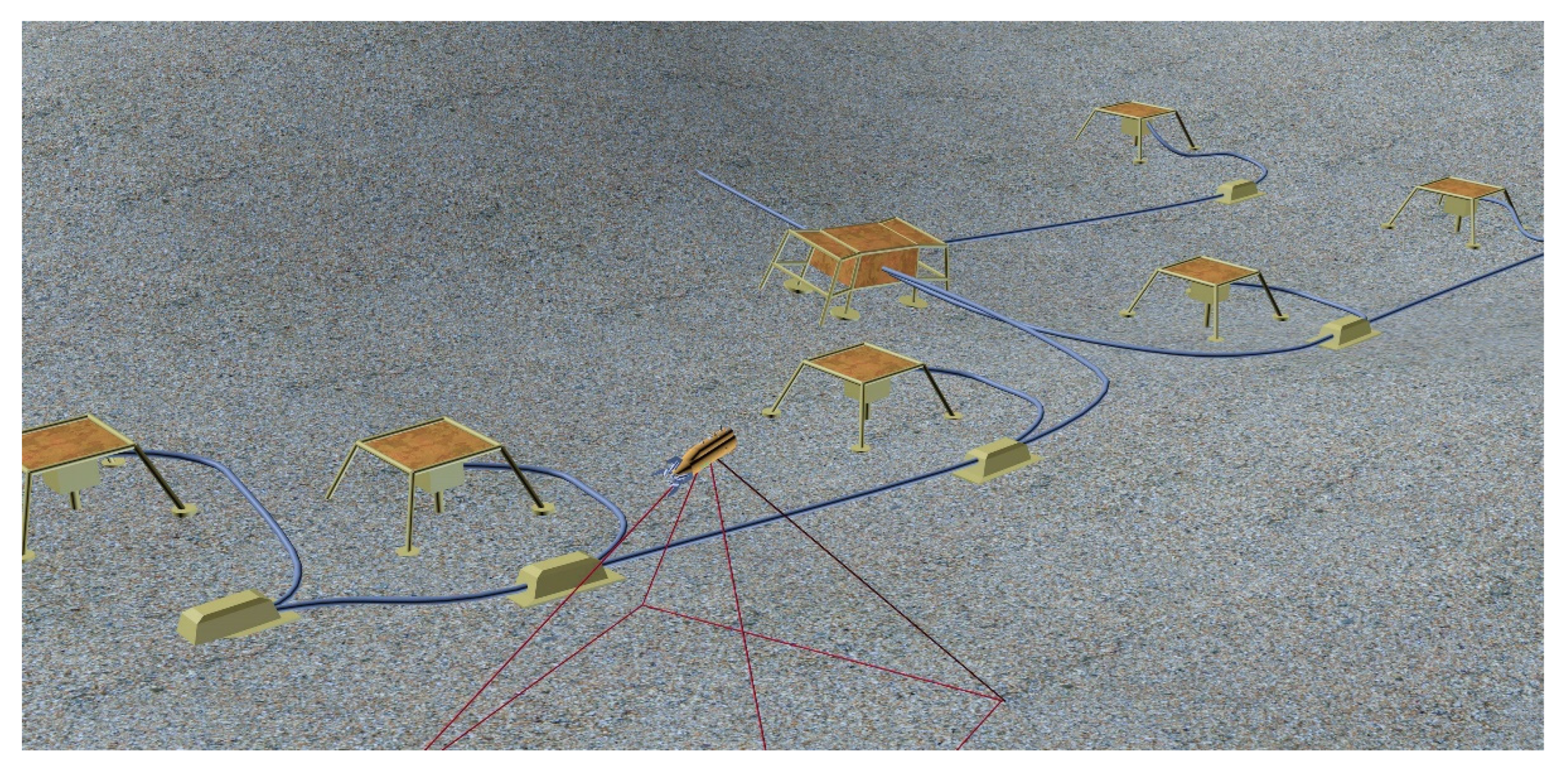
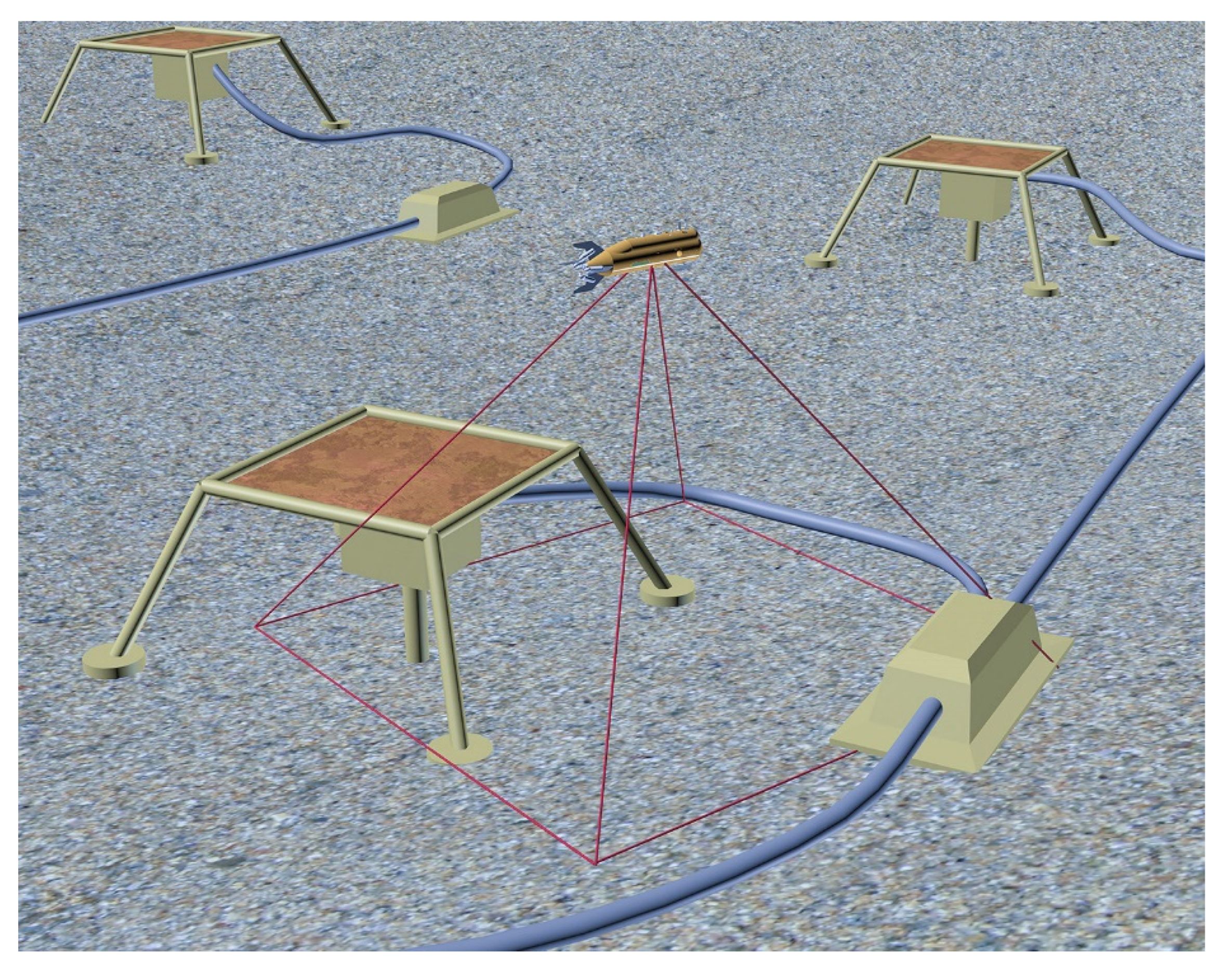
It is assumed that, when performing an inspection, the standard navigation systems on board an AUV do not provide the sub-meter accuracy required for inspection. These means are only used for organizing the AUV’s approach to the object to be inspected. Therefore, the issue of AUV navigation using video information, which can potentially provide a high-precision coordination of AUV with respect to an underwater object, is considered attentively. AUV is suggested to be equipped with a stereo camera recording a video stream during the vehicle’s movement along the trajectory planned for the inspection mission. A local cluster of SPS consisting of several underwater objects distributed over a limited area is considered as an object of inspection (a schematic example of an SPS cluster, as a virtual scene, is shown in
Figure 1). The SPS has a two-level structure. Each object is characterized by its own geometric model, which is represented by 3D feature points (FP) that define the spatial structure of the object [
23]. The FP coordinates are set in the coordinate system (CS) of the object model. At the top level, all object models are combined into a SPS model. The CS of each object is referenced to the SPS CS via a coordinate transformation matrix. The goal is to organize the precision movement of the AUV in the SPS CS using the visual navigation method (VNM) in real time mode.
Since the visual odometry technique tends to accumulate navigation errors during long movements [
26], in this article, we present an approach based on the application of a virtual coordinate reference network (VCRN) to improve navigation accuracy and reduce computational costs. The VCRN consists of two types of reference points. Reference points of first type
are aimed at reducing the error of the VNM used [
41], while the AUV is making long-distance movements during inspection.
Reference points of second type
—direct referencing of the AUV coordinates to a subsea object through the use of our previously developed technique of object recognition/identification [
42,
43]—provides referencing of the CS of the current AUV position to the SPS CS, and, accordingly, provides calculation of the AUV trajectory in the coordinate space of the SPS.
According to the proposed technique, periodic inspection of the SPS cluster using AUV begins with a preliminary (overview, or survey) run over the cluster objects. The survey trajectory is set in such a way to move over the most characteristic places of the cluster (places with the highest probability of identification). Moreover, the trajectory should be such a length to make the error of video dead-reckoning accumulated during the movement remain within the required sub-meter accuracy. During the survey run, the initial state of the VCRN is formed. During subsequent runs performed to inspect structures, additional can be created. As a result, with each run along the new trajectory, the virtual network grows thicker, which eventually increases the accuracy of AUV navigation in the area of SPS location in subsequent operation sessions.
is understood as some position of the survey trajectory of the AUV, with which the data set is associated, required to link the CS of the current position of the AUV (inspection trajectory) and CS . This data set includes:
a stereo-pair of images taken with the camera at this position of the AUV trajectory;
coordinates of this AUV position in the CS of the initial position of the AUV trajectory (with VNM used);
matrix of geometric transformation of coordinates from the AUV CS at the initial trajectory position into the CS (with VNM used);
parameters of filming that determines the part of the bottom visible to the camera;
measure of the localization accuracy of this .
AUV’s coordinate referencing to the allows partial reduction in the error accumulated by visual odometry in the previous segment of the trajectory due to the use (at the “loop closing” moment) of more accurate navigational data stored in VCRN . At the same time, significant computational costs are not required in the referencing process because only a single transformation is calculated: from the CS of the current AUV position into the CS; the data already calculated and stored in is used.
A necessary condition for referencing is the presence of a visible area common for the AUV video cameras from the current position and from the .
Reference points of second type are used for the transformation from the CS of into the CS of the SPS object. Each stores a matrix of AUV referencing to one of the SPS objects. The process of forming and referencing to is the same as that for , but, unlike it, s can be located all along the trajectory, since the error in calculating the matrix above is not related to the trajectory length.
It should be emphasized that the inspection operation does not necessarily require the use of exact absolute coordinates (in the external CS) of AUV since the mere knowledge of its location in the SPS coordinate space is sufficient to control AUV movements with respect to SPS objects.
The calculation of the AUV trajectory can be performed both in the CS of the object and in the external CS, which is considered to be the CS of the initial position of the trajectory. This CS for the overview (initial) trajectory will be denoted as WCS1, and for the current (new) trajectory, the analogous CS will be denoted as WCS2. For each new trajectory, the necessary connection between WCS2 and WCS1 is provided.
Thus, the deployment of VCRN to reference AUV to SPS objects is aimed to maintain the required accuracy of AUV coordination during long-distance movements along an inspection trajectory, while minimizing computational costs.
3. Methods
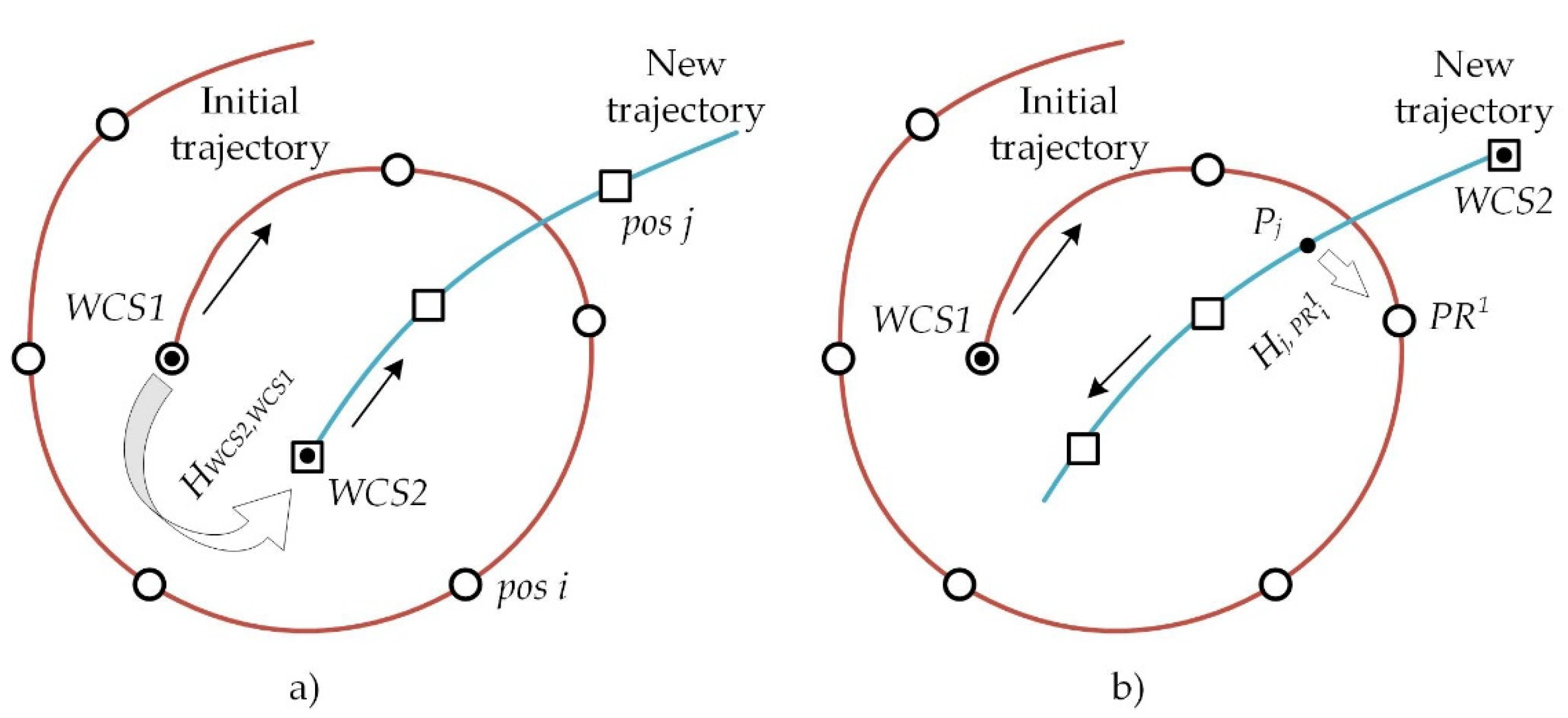
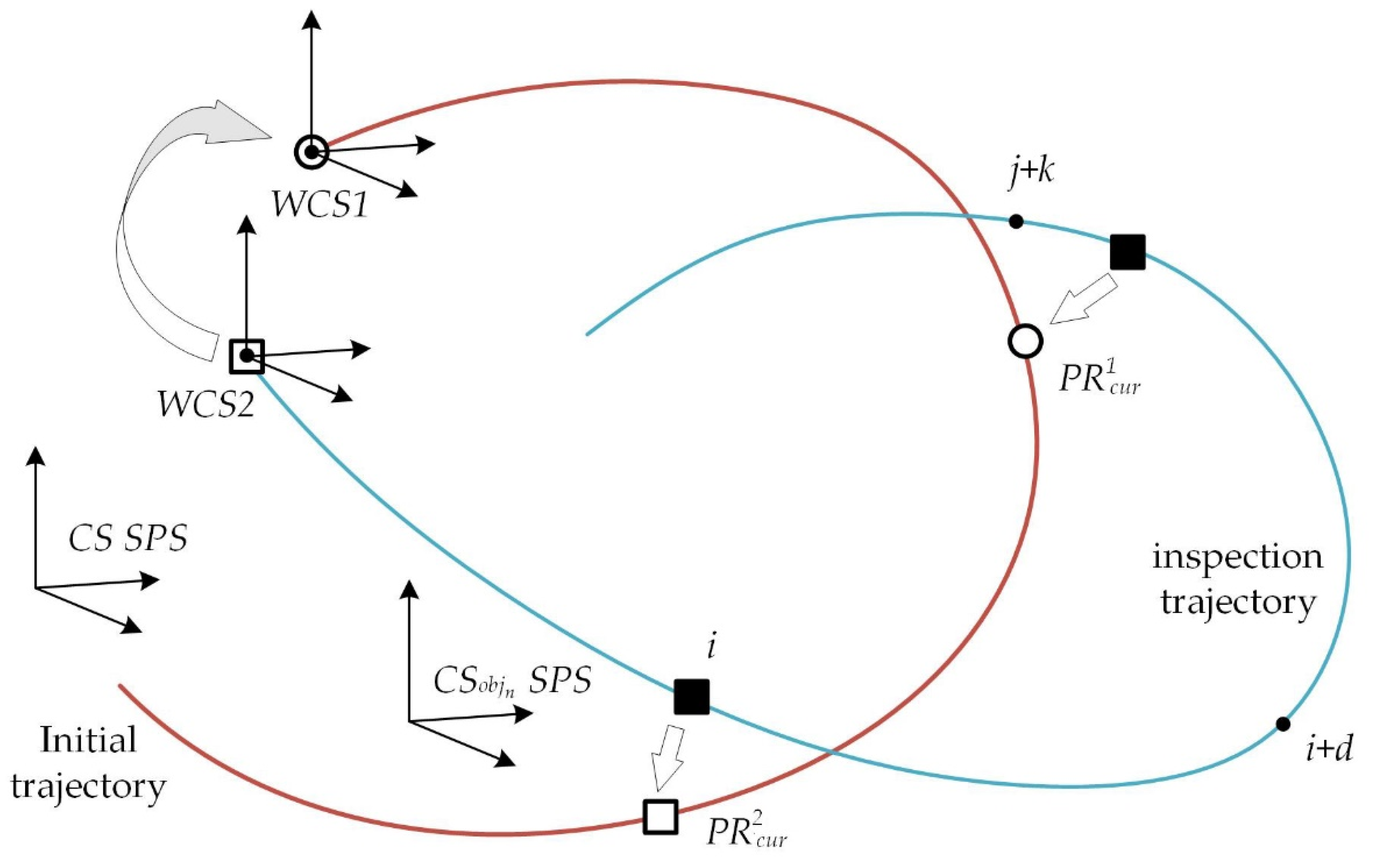
Figure 2 illustrates the coordinate systems and designations applied. The synonyms initial/overview/survey/trajectory 1 will also be used to designate the preliminary trajectory mentioned below. The
WCS1 coordinate system is associated with it. An inspection trajectory is also called a working trajectory, trajectory 2, or a new trajectory in different contexts. The
WCS2 coordinate system is associated with it.
The following designations will further be applied:
is the trajectory 2 starting point in the WCS2;
is the trajectory 2 (working) starting point in the WCS1;
is the AUV coordinates in the AUV CS at the i position of trajectory 2, i.e., ;
is the AUV coordinates at position i of the trajectory 2 in the SPS CS;
is the coordinates of point at the position i trajectory 2 in the WCS1;
is the coordinates of position at the position i trajectory 2 in the WCS2;
SPS is the SPS object with identifier n;
—reference point of the type t at position s trajectory 1 (t = 1—first type, t = 2—second type, s—position number, if s = cur, then at current position);
is the coordinate transformation matrix from the AUV CS at the ith position of trajectory 2 into the CS of of VCRN at position s of trajectory 1;
is the coordinate transformation matrix from the WCS2 to the WCS1;
is the coordinate transformation matrix from the ith position to the jth position of trajectory 2 in the WCS2 (obtained by the VNM);
is the coordinate transformation matrix from the start point of trajectory 2 into the jth position of the AUV trajectory (in the WCS2);
is the coordinate transformation matrix from the CS of (trajectory 1) into the CS of the SPS object n, stored in .
3.1. Forming a Virtual Coordinate Reference Network
The reference process consists of several steps:
comparison of feature points in the stereo-pair images taken from the current position of the AUV trajectory and the stereo-pair images stored in a data set associated with a virtual point of referencing;
calculation of spatial coordinates of the respective two 3D clouds from the resulting set of features compared;
calculation of the local coordinate transformation matrix relating the CS of the current AUV position and the CS of reference point;
extraction of the stored transformation matrix into the required CS. In the case of referencing to an SPS object, use of the object recognition algorithm with calculation of the reference matrix.
3.1.1. Formation of First Type Reference Points
As noted above, the initial state of VCRN is formed when the AUV is moving along a trajectory over the SPS for the first time. With the repeated inspection procedures over the same SPS places, the VCRN is extended.
are always generated at the initial part of the trajectory, where no significant accumulation of error occurs in the VNM operation. A respective data set is generated and stored in
(see above). Since the cumulative error in the navigation accuracy calculation depends on a multitude of factors (such as seafloor surface topography, speed of AUV movement, frame rate, trajectory parameters, and calculated step on the trajectory), the threshold value for determining the length of the initial trajectory segment is estimated experimentally. Accordingly, the number of
formed in this trajectory segment is selected in advance, for the reason of tradeoff between the requirements to navigation accuracy and the need for real-time mode. The necessary “relation” of the two trajectories to build up VCRN implies referencing the second trajectory to the
WCS of the initial trajectory. There are two possible options for the spatial position of the new trajectory starting point relative to the initial trajectory starting point (
Figure 3).
In the first option, the new trajectory starting point is located in the neighborhood of the initial trajectory starting point (
Figure 3a). In this case, the relation is performed by comparing features in the stereo-pair images taken at the initial positions of the former and latter AUV trajectories (similar to that performed in VNM when calculating the local transformation).
Thus, the coordinates of the new trajectory starting point are calculated as follows:
where
is the new trajectory starting point in the
WCS1;
is the new trajectory starting point in the
WCS2;
is the matrix of geometric transformation from the CS of the new trajectory starting point to the CS of the initial trajectory (obtained by matching the features on the images related to the starting positions of the two trajectories). Here and below in the text, we use the matrix form of geometric transformations, where a point is represented by a line of homogeneous coordinates, while the matrix has a dimension of 4 × 4.
In the second option, the new trajectory start point is located at a distance from the initial trajectory start point (outside its neighborhood) (
Figure 2b). In this case, the new trajectory is referenced to one of the
of the initial trajectory. The first
to which referencing from the point of the new trajectory becomes possible is assumed to be such a
. For this, a stereo-pair of images taken at the point (AUV position) of the new trajectory and a stereo-pair of images belonging to the
of the initial trajectory are used. The referencing process is based on the comparison of features in the stereo-pair images, as in the previous case. Then, the coordinates of the new trajectory start point are converted into
WCS1 as follows:
where
is the new trajectory start point in the
WCS1;
is the new trajectory start point in the
WCS2;
is the coordinate transformation matrix from the
WCS2 of the new trajectory start point into the CS of the
jth position of the new AUV trajectory;
is the coordinate transformation matrix from the CS of the
jth position of the new AUV trajectory into the CS of the
(
ith position of initial trajectory);
is the coordinate transformation matrix from the CS of the
ith position initial trajectory into the
WCS1.
3.1.2. Formation of Second Type Reference Points
The use of points solves the same “loop closing” problem—implementation of the navigational advantages of revisiting the same places—as done by the use of . In the first case the trajectory of the AUV is refined due to the more accurate navigation information stored in ; in the second case the conversion from the AUV CS into the coordinate space of the SPS object is calculated using the algorithm of SPS object recognition. It is essential that access to the recognition algorithm can be made from any point of the trajectory. points are formed at the first access to the algorithm; at subsequent references to PR2, the already calculated coordinate conversion matrix is used. stores a set of data similar to that stored in , which allows for referencing the AUV to .
Algorithm of referencing the AUV coordinates to SPS object. The input data for the algorithm are images taken with the stereo camera and a pre-built geometric model of SPS. The SPS object model is a set of 3D points belonging to it, which characterize its spatial structure. The points are set in the CS related to this object. At the first stage of the algorithm’s run, characteristic points to build the 3D cloud are highlighted in the images obtained with the camera (using a Harris Corner Detector). The points of the 3D cloud are described in the AUV CS. Then, recognition of the subsea object is performed based on the analysis of the points of the obtained 3D cloud. The analysis consists in searching for 3D points that match the geometric model of the object. The matching of the identified 3D cloud points to the points of the object model is evaluated on the basis of a structural coherence test (similar relative positions of spatial points in the compared sets). The transformation matrix, relating the AUV CS and the CS of the SPS object, is calculated using the identified points. A detailed description of the algorithm can be found in [
44,
45].
3.2. Referencing of AUV to Reference Points during a Working Mission
To be successful, the planned inspection mission requires precision navigation of AUV in the SPS space, in particular, coordination of the AUV relative to each of the SPS objects. The necessary accuracy is achieved through the coordinated operation of the VNM, the technique of AUV referencing to the and of the formed virtual network VCRN. While the AUV is moving along the trajectory, regular search and referencing to the specified reference points (if possible) are carried out, and the AUV position in the SPS CS is calculated. The data stored in reference points of VCRN are used. During referencing to , the error in the VNM operation is partially reset due to the “loop closing problem” solution, while the minimization of computational costs in referencing the AUV to SPS structures is provided by using the conversion matrices from AUV CS to SPS CS, stored in .
The work of the AUV to
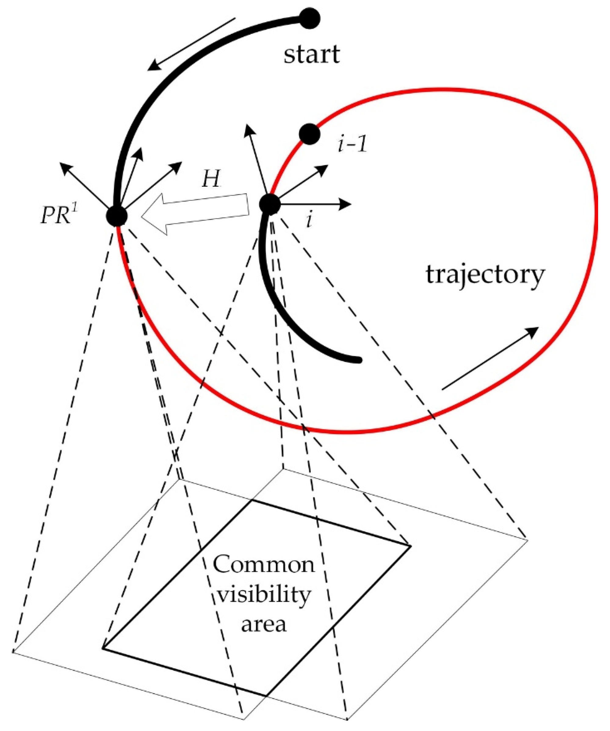
referencing algorithm (in the case of a single trajectory) is illustrated in
Figure 4. The search and verification of reference points to which referencing is possible is carried out on the basis of known data on the camera parameters and the calculated trajectory parameters (AUV position coordinates etc.). A necessary condition is the overlap of the seafloor area visible for the stereo camera at the current
ith position of the trajectory, and the corresponding visibility area for
. The overlap is calculated using a threshold distance that guarantees the necessary degree of overlap of visibility areas. Here, the predicted rate of accumulation of the AUV navigation error through dead-reckoning is also taken into account. In the case of multiple AUV’s runs over SPS objects, all coordinate calculations should be performed in a single coordinate space, which is provided by the presence of a geometric transformation between
WCS1 and
WCS2. The
WCS1 and
WCS2 are related by the visual odometry technique.
Calculation of the coordinate transformation matrix , relating the AUV CS at the ith position and the CS when the condition of overlapping visibility areas is satisfied, is performed by the ICP algorithm.
After referencing the AUV to the
, the current result of the VNM operation at the
ith position is adjusted by using stored data. The adjustment is performed as follows: the chain of local transformations, accumulated from the initial position to the
ith position, is replaced by a shorter one belonging to
, plus the transformation
H relating the current position with
. In
Figure 4, a segment of the trajectory from the start position to the
position corresponding to this short chain is highlighted as a bold line. Thus, the error corresponding to the trajectory segment from
to the
ith position (in the figure, this segment is highlighted as a thin line) is reset, which leads to an abrupt decrease in the error.
The coordinate referencing of AUV to is performed in a similar way using the ICP algorithm that links the CS of the current position of the AUV and the CS of .
The direct referencing of the AUV to the SPS object is performed using the transformation matrix stored in (obtained during the formation of using the above mentioned recognition algorithm).
3.3. Calculation of the AUV Inspection Trajectory Using Virtual Coordinate Referencing Net
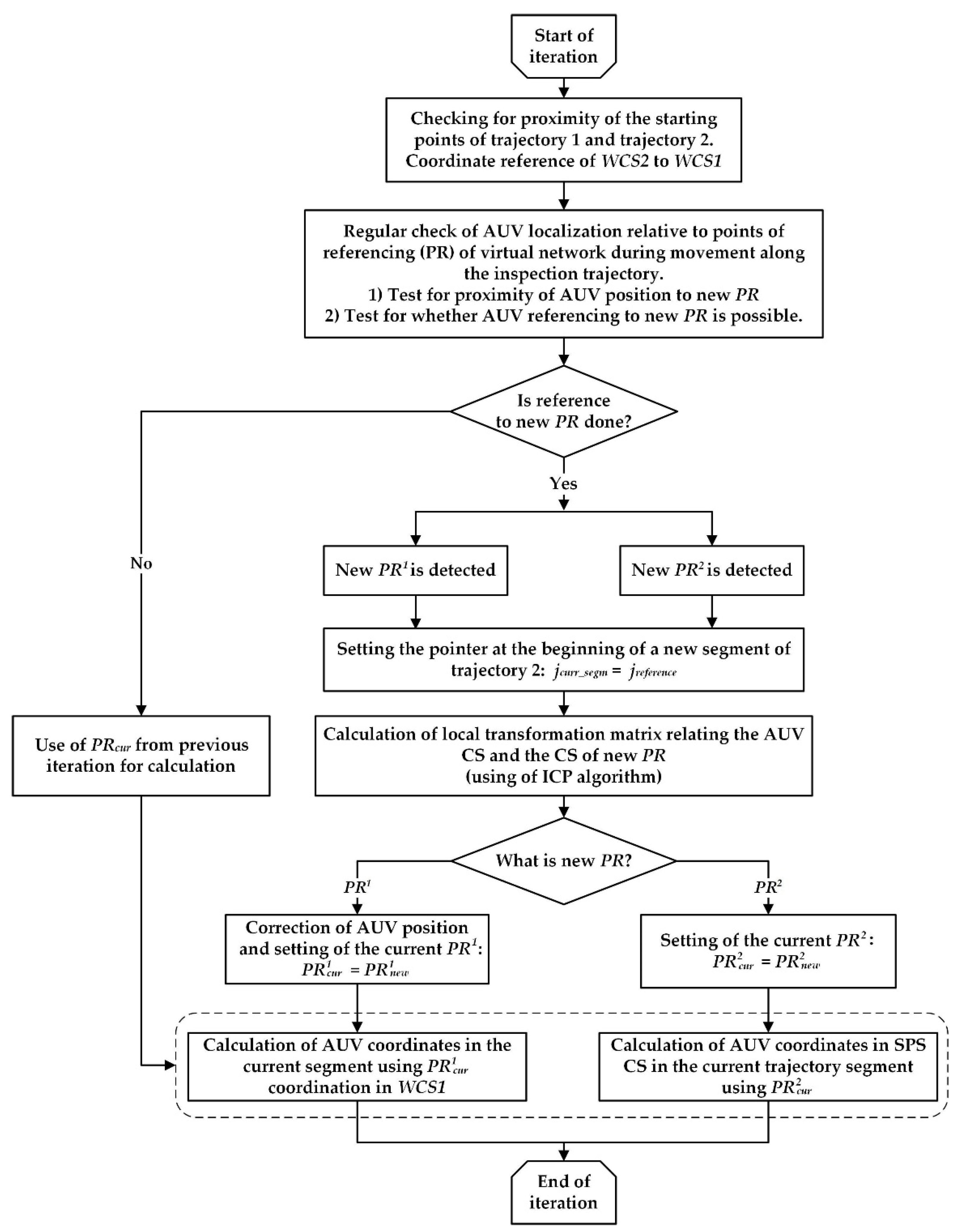
The proposed technique for calculating the inspection trajectory is based on regular AUV referencing to the reference points of VCRN during movement. The computational scheme for calculating the trajectory is shown in
Figure 5. After the AUV enters the specified area of the SPS location (using standard navigation systems), the visual navigation system starts working. In this case, the potential for referencing an AUV to any reference point is evaluated:
the AUV localization relative to the points of referencing of the virtual network VCRN is checked continuously (with a certain frequency). For each point of referencing, the square of the neighborhood is outlined (with rough coordinate setting in the external CS); i.e., a test is performed if the AUV position belongs to this neighborhood;
after confirming the AUV’s entry into the neighborhood area, the possibility of referencing the AUV to the point of referencing is tested, i.e., availability of a common visibility area is checked (based on the known data on camera parameters and calculated trajectory parameters). Upon confirming the possibility of referencing, the AUV is referenced to the virtual point. If referencing was done to the , then the current position is corrected. This leads to a step-like increase in navigation accuracy. If the referencing was done to the , then the AUV coordinates at subsequent positions are calculated using the matrix of referencing to the SPS object that is stored in the .
As shown in the computational scheme (
Figure 5), the trajectory calculation algorithm is based on the following main points:
the inspection trajectory conditionally divided into segments determined by the points of AUV referencing to and to ;
the trajectory is calculated for each of the segments in taking into account the previous AUV referencing;
the calculation of AUV motion within a segment is performed by the VNM method (visual odometry);
the calculation of the AUV coordinates in the SPS object CS and/or in WCS1 (initial trajectory CS) on the current segment is provided by the joint use of the VNM method and the data stored in the involved virtual network reference points.
For , these are the coordinates of the reference point and the coordinate transformation matrix in WCS1, which improves navigational accuracy. For , this is the matrix of direct binding of AUV to the SPS object, which allows for reducing computational costs.
The corresponding resulting coordinate transformation matrices are constructed based on the union of the above participating coordinate transformation matrices.
3.4. Demo Example of the Trajectory Calculation Algorithm Using VCRN
As mentioned above, the inspection/working trajectories are divided into two types, depending on the proximity of the starting point of the working trajectory to the starting point of the initial/survey trajectory, since each type implements its own way of linking WCS2 (CS of the working trajectory) with WCS1 (CS of the initial trajectory). For a clearer representation of the algorithm, consider examples of how it works for each of the two types of work trajectories:
the starting point of the working trajectory is located in the neighborhood of the ini-tial trajectory beginning;
the starting point of the working trajectory is located outside the neighborhood of the initial trajectory beginning.
3.4.1. Close Location of the Starting Points of the Trajectories
Figure 6 illustrates the process of calculating the coordinates of the current position of the AUV inspection trajectory using coordinate referencing to the virtual
and
of VCRN located on the initial trajectory.
We refer to the last point to which referencing was made from some position of the inspection trajectory as the current point of referencing. Denote the current point of referencing as
for
and as
for
. After referencing to
at the
ith position, the AUV coordinates at an arbitrary position (
i +
d) can be calculated using VNM and by coordinate transformation into the CS of the SPS object, stored in
. Note that, according to the above described SPS model, the CS of each SPS object is related to the SPS CS and, therefore, the resulting conversion from the AUV CS into the CS of the SPS object also means referencing to the SPS CS. The VNM technique provides the conversion of
from the CS at the
ith position (at which the referencing to
was performed) into the CS of the current position (
i +
d). Then, the desired transformation
from the AUV CS at the
i + d position of trajectory 2 into the CS of
SPS is calculated as follows:
is the transformation matrix from the CS of
into the CS of the SPS object
n, stored in
.
Accordingly, the AUV coordinates are recalculated from the CS of the AUV position (
i +
d) into the CS of SPS as follows:
is the AUV uniform coordinates at position (
i +
d) of trajectory 2 in the CS related with the AUV.
In the next segment of trajectory 2 (after being referenced to
), the transformation
from position
j + k into the CS of SPS
is calculated in a similar way:
Since referencing to
is performed at the
jth position, the position of the AUV in the
WCS1 can be refined due to this reference:
Thus, the matrix
is calculated as follows:
where
is the coordinate transformation matrix from the CS of
(calculated when forming
) into the
WCS1.
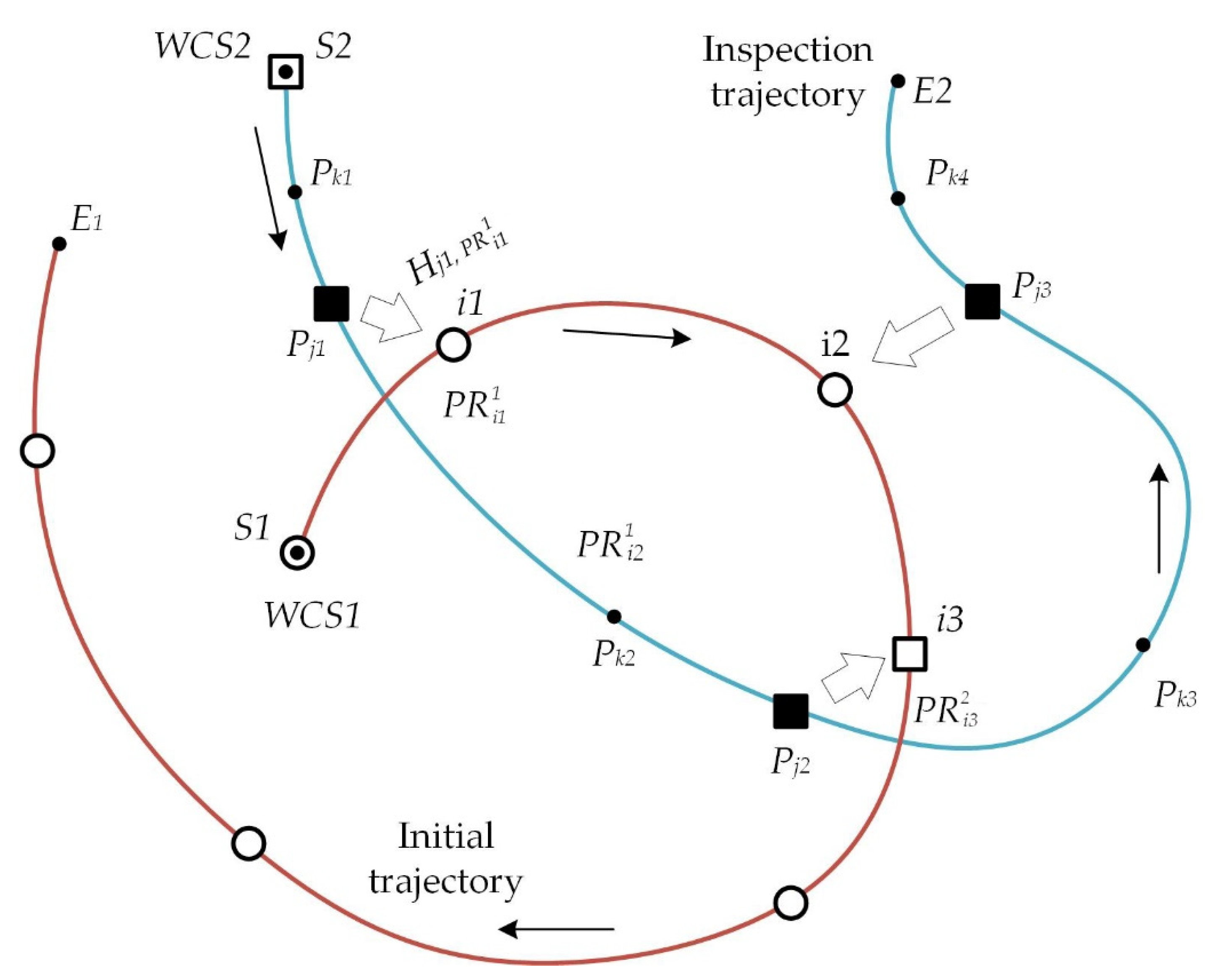
3.4.2. The Far Location of the Starting Points of the Trajectories
First, calculate the matrix relating the
WCS2 with the
WCS1, using the AUV reference at point
of trajectory 2 to
of trajectory 1 (see
Figure 7)
The coordinates of the start point
S2 in the
WCS1 will be, accordingly, as follows:
Now calculate trajectory 2 by the proposed technique in each of the segments separately.
Since AUV movement is controlled in increments, in the absence of reference to
and to SPS objects, therefore, both
WCS1 and
WCS2 can be used. Then, the coordinates of an arbitrary point
at position
k1 (trajectory 2) are transformed in the
WCS1 as follows:
In the
WCS2, the coordinates are as follows:
- 2.
Calculation of trajectory 2 in the segment
Calculate the coordinates of an arbitrary point
at position
k2 in the
WCS1:
Here, the matrix
is calculated by the following equation:
where
is the coordinate transformation matrix from the position
S1 to position
i1 of trajectory 1 (calculated when forming
).
- 3.
Calculation of trajectory 2 in the segment :
At position j2, the AUV is referenced to the SPS object. As the AUV proceeds to position j3, the VNM works with its respective error accumulation.
Calculate the coordinates of an arbitrary point
in the CS of SPS:
where
is the coordinate transformation matrix from the CS of
to the CS of SPS (obtained using the algorithm of AUV referencing to SPS).
Now we can relate the two coordinate systems:
WCS1 and CS of SPS. For this, calculate the coordinates of three points in this segment in the CS of SPS (using Equation (14)) and in the
WCS1. The coordinates of the point in the
WCS1 are calculated using the current reference of AUV to
(in this case, it is
) by:
For calculation of the matrix , see Equation (13).
Using these three points, calculate the transformation matrix (which will be required for calculating the trajectory in the following segment).
- 4.
Calculation of trajectory 2 in the segment :
There are two possible approaches to calculating the coordinates of an arbitrary point in the segment in the coordinate space of SPS:
Approach 1. The coordinates of an arbitrary point
in the segment
in the
WCS1 are calculated using the AUV reference to
(the reference is assumed to reset the error accumulated by visual odometry in the segment
). The previously obtained transformation
is applied to these coordinates:
where
is the coordinate transformation matrix from the
WCS1 to the CS of
(calculated when forming
).
Approach 2. The coordinates of an arbitrary point
in the segment
are calculated using the last AUV reference to SPS (the same as for
), i.e., as follows:
4. Results
To assess the efficiency of the proposed technique (compared to the standard visual odometry technique), two types of experiments were set up with:
The personal computer specifications were as follows: AMD Ryzen 9 3900X 12-Core Processor 3.60 GHz//32Gb//AMD Radeon 5600XT. A Karmin2 camera (Nerian’s 3D Stereo Camera, baseline 25 cm) was used for the laboratory experiment. For processing the imagery taken, the feature detector SURF from the OpenCV library was used.
4.1. Simulator
The simulator used for experiments is designed to solve the problems of developing, researching and debugging algorithms and methods used in the robot control system. Examples of such tasks are: automatic navigation; search and survey of underwater objects; survey missions; construction of terrain maps; and "intelligent behavior" algorithms (trajectory planning, obstacle avoidance, emergency situations processing, group works). The main functionality of the simulator:
simulation of the mission of the robot;
modeling of the external environment;
simulation of the operation of sensor onboard equipment.
Other functionality allows you to:
use the simulator as a training complex for AUV operators;
test the operability of the AUV equipment and onboard software when it is connected to the virtual environment of the simulation complex in the HIL mode (real equipment in the simulation cycle);
visualize simulation results for any moment of the mission.
The simulator architecture is built using distributed computing, a client-server model, plugin technologies, and hybrid parallelism (GPGPU + CPU) in functional blocks.
4.2. Virtual Scene
The experiment consisted in comparing the accuracy of the technique proposed here with that of the standard visual odometry technique for calculating an AUV inspection trajectory. For each of the techniques, the error relative to the true (set in the model) trajectory was calculated. The experiment was conducted as follows:
in the initial segment of the preliminary trajectory (trajectory 1), of VCRN were formed;
for the working trajectory (trajectory 2), the AUV navigation error was calculated in two variants:
- (a)
with the use of visual odometry only;
- (b)
using (in addition to visual odometry) two types of coordinate references: referencing to the
of VCRN and direct referencing to SPS object using the above-mentioned authors’ algorithm [
43].
The scene generated in the simulation system [
45] with an AUV moving along the trajectory over a SPS is shown in
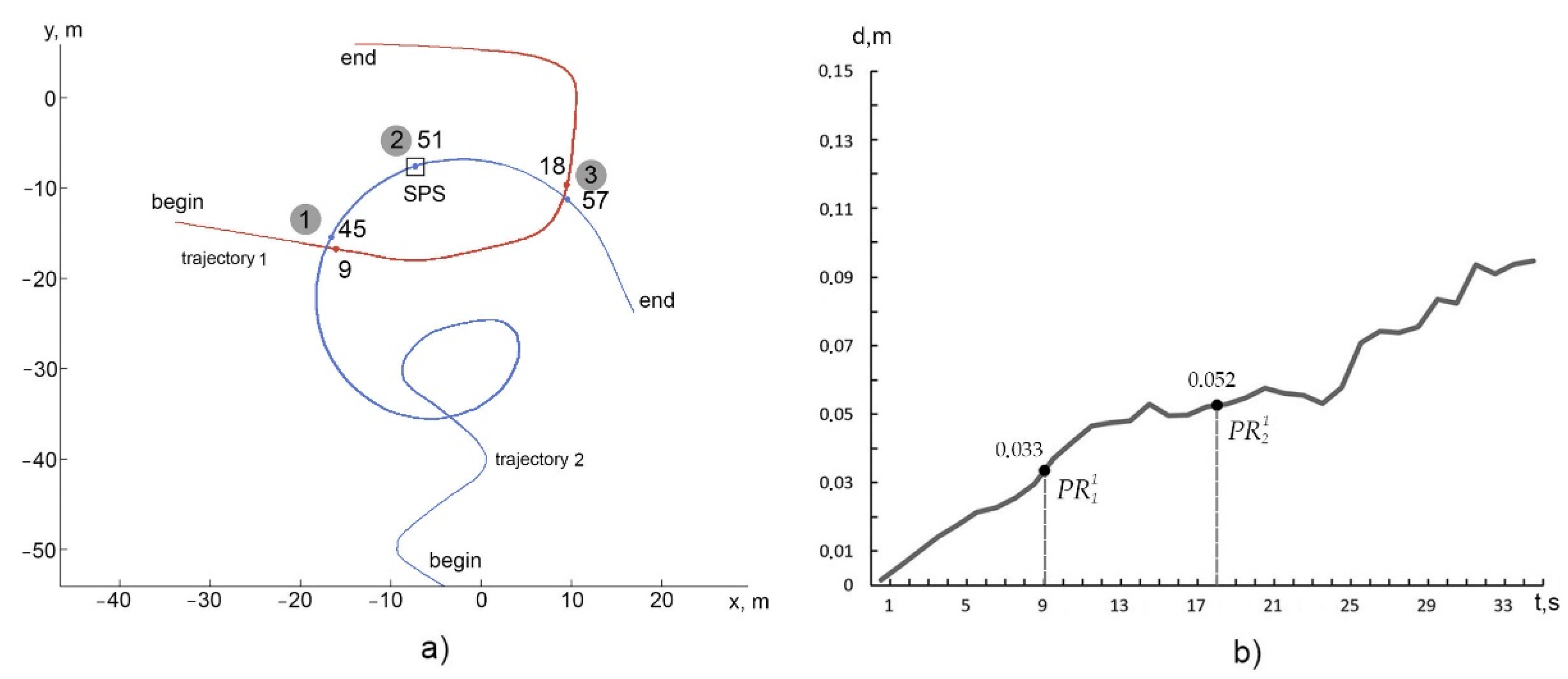
Figure 8; the shapes of trajectories 1 (base trajectory) and 2 (working trajectory) are shown in
Figure 9a (in the seafloor plane). When modeling the seafloor topography, an actual texture was used. The altitude of the AUV movement over SPS objects was from 3 m to 5 m, the frame rate was 10 fps, and the image resolution was 1200 × 900. The AUV coordinates were calculated at the trajectory positions every 10 frames of photography. Therefore, the numbers of the positions indicated in the figures below correspond to the time values of the AUV movement measured in seconds.
Figure 9b shows a graph of the error of trajectory 1 calculated by the standard technique. The error is calculated as a deviation from the trajectory set in the model. In the initial segment of trajectory 1, at positions 9 and 18 (see
Figure 9a,b), the virtual points of referencing
and
of VCRN are formed, to which the coordinates of the AUV moving along trajectory 2 are referenced. The AUV’s referencing the specified
is respectively performed at positions 45 and 57 of trajectory 2 (
Figure 9a). The AUV is also directly referenced to the SPS object at position 51 by the above algorithm [
43].
Trajectory 2 was calculated by the proposed technique for each of the segments (similar to the diagram in
Figure 7) using Equations (10)–(15). It was necessary to evaluate how these two types of coordinate references (to the points of referencing
PR1 VCRN and to the SPS CS) reduce the cumulative error (characteristic of visual odometry during long-distance AUV movements) when calculating the AUV’s trajectory 2.
Prior to the above-described experiment, estimates of the accuracy of the programs used for referencing the AUV coordinates to the SPS CS and to VCRN were obtained for this scene:
for the technique of direct AUV referencing to SPS, an error of 5.4 cm was obtained in this scene;
the error of referencing to VCRN in this case is determined by referencing to the two above-indicated .
The accuracy error during generation was for them (see
Figure 9b), respectively, 3.3 and 5.2 cm. Ultimately, the navigation error of the AUV at the current position after binding to
is the sum of the
error and the coordinate transformation error between the
CS and the trajectory position CS. The graph of the error in calculating trajectory 2 by the proposed technique compared to that obtained by the standard technique for this virtual scene is shown in
Figure 10. As can be seen from the graph, the error of navigation in referencing to the VCRN points decreases abruptly.
With the reference to the first (at position 45), the error decreased, as compared to the standard technique, from 27.1 cm to 9.4 cm. In the case of reference to the SPS CS, the error decreased (after increasing to 16.7 cm) to 8.7 cm vs. 43.6 cm for the standard technique. In the case of reference to the second (at position 57), the error decreased to 14.2 cm vs. 51.8 cm for the standard technique.
Thus, both types of reference points reduce the AUV navigation error accumulated by the VNM method stepwise to an acceptable level. The difference between them is that: a) the efficiency of points (in terms of accuracy) is higher, the closer they are to the beginning of the trajectory. While the effectiveness of points does not depend on their location on the trajectory, it is determined by the accuracy of reference to the object, which is provided by the applied referencing algorithm; b) items of the first type provide AUV coordination in the WCS, and items provide coordination directly in the CS of the object.
4.3. Experiment with a Karmin2 Camera
The experiment was set up under laboratory conditions: the camera was moved manually at an altitude of 1.5 m from the floor at a speed of ≈0.25 m/s. As in the experiment with the virtual scene, a run with the camera was made, first, along a “preliminary” trajectory (trajectory 1) for organizing the VCRN (the trajectory was calculated by the visual navigation technique) and then along the “working” trajectory (trajectory 2) (see
Figure 11a) that was calculated by applying our proposed technique.
The efficiency of the proposed technique was evaluated by comparing the results of calculation of trajectory 2, which was obtained in two ways:
the traditional visual odometry technique;
the proposed technique, i.e., using coordinate referencing to the and of VCRN.
A paper box was used as an object. The accuracy error of the camera localization was estimated as a deviation of the calculated trajectory from the true (drawn on the floor) trajectory. In this case, a trajectory projection onto the floor was calculated, since it was difficult to accurately measure the Z-coordinate for the moved manually camera. The start points of the trajectory 1 and 2 in this experiment are superimposed only for the purpose of avoiding the additional error in calculating the result; in actual scenes, this is not necessary.
On trajectory 1 (see
Figure 11a), two
PRs were formed:
at position 32 and
at position 68. The photograph frame numbers are plotted along the
X-axis. As can be seen in the graph (see
Figure 11b), the accuracy error for trajectory 1 at position 32 is 0.028 m; at position 68, it is 0.031 m. This accuracy fits the purpose of
PRs.
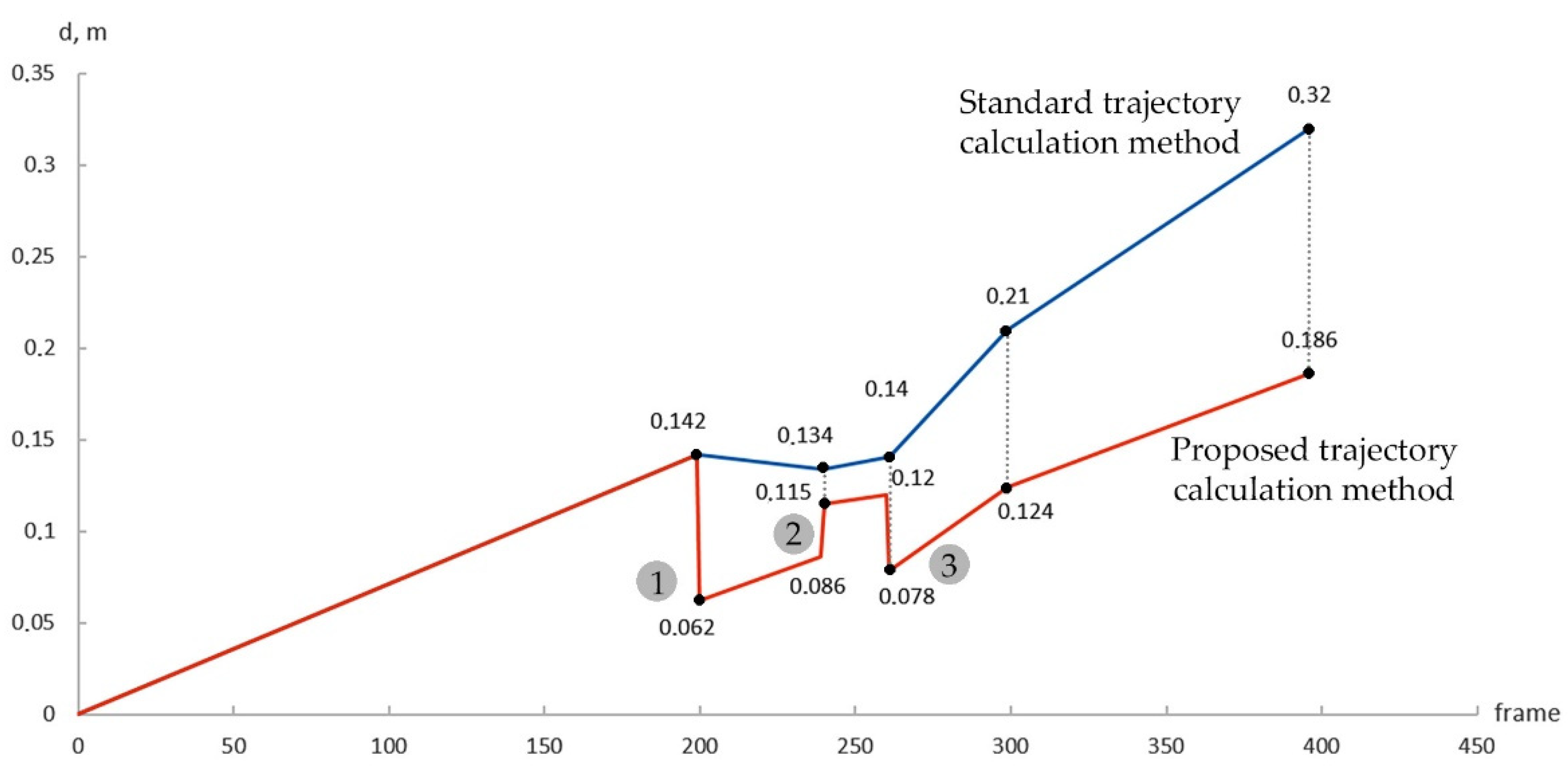
Figure 12 shows a comparison between the accuracies of trajectory 2 calculation by the standard technique (visual odometry) and by the proposed technique. The referencing to
was performed at position 200; the referencing to
, was at position 261; and the direct coordinate referencing to the object (the box) was at position 239. The graph shows that the error in the initial segment of the trajectory up to position 200 increases (due to the accumulation of the error of the visual odometry technique); after referencing to
, it decreases from 0.142 m to 0.062 m. Then, the error increases again (due to the accumulation of visual navigation error) to 0.086 at position 231 and becomes 0.115 m after referencing to the object (this accuracy is provided by the algorithm for recognition and referencing to the object). The error value at this position for the visual odometry technique is higher, 0.134 m. Then, the error increases from 0.115 m to 0.120 m at position 261 also due to the error accumulation, and, upon referencing to
, it decreases to 0.078 m.
Assessment of computational costs. It follows from the analysis of the computational scheme (
Figure 5) that the main computational costs are in the calculation of the local transformation performed at each step in the VNM method. However, this cost is significantly lower due to the use of the results of the most labor-consuming operations (extraction and comparison of 2D features in stereo-pair imagery, construction of a 3D cloud belonging to
) stored in the
.
To obtain specific estimates on the cost of referencing to
, measurements were made on an actual trajectory with a length of 38.4 m, including 397 frames. The trajectory was filmed with a Nerian Karmin2 stereo camera providing an image resolution of 1600 × 1200 × 2 px (stereo) and a frame rate of 10 fps. The trajectory was calculated by the VNM technique. The cost of referencing to a single reference point was estimated. The cost of calculating one frame by the VNM technique (using an AMD Ryzen 9 3900X) amounted to 271.3 ms. The additional cost of detection and referencing to a single virtual point was 37 ms, which constituted 13.6% relative to the VNM cost. Hence, we can draw a general conclusion that the computational costs of the use of virtual coordinate reference points when moving along the inspection trajectory are quite acceptable. Under lab conditions, the AMD Ryzen 9 3900X produces approximately 5 fps. To test the speed on a weaker CPU, the algorithm was tested on an available Intel Core i5-2500K, where approximately 1.2 fps was obtained. The more productive Intel Core i7-1160G7, which is installed on modern and promising AUVs, (
https://www.cpubenchmark.net/compare/Intel-i5-2500K-vs-AMD-Ryzen-9-3900X-vs-Intel-i7-1160G7/804vs3493vs3911, Sydney, Australia, 12 August 2022) is guaranteed to deliver over 1 fps.
To increase the operating speed of the visual navigation system in general, a less cost-consuming VNM is required.
5. Discussion
It can be seen from the comparative graph for the virtual scene (
Figure 10) that from a certain point in time of the AUV movement (in this case, from the 30th second) the accumulated navigation accuracy error begins to grow rapidly. Referencing to VCRN points, as expected, reduces the error almost to the value of the error of the point itself. At that, the error in the
point is less than in the
point. This follows from the fact that the
point was formed on trajectory 1 later than the
point. Points of direct referencing to the object also reduce the error to an acceptable level. They may or may not be on trajectory 1, as shown in the example in
Figure 7 and in the experiments (
Figure 9a and
Figure 11a). In the first case, the referencing matrix calculated by the applied referencing algorithm is stored in the referencing point
and can be used in subsequent inspection paths (reduction of computational costs). In the second case, the reference to the object is carried out after the execution of the mentioned referencing algorithm. Additional time is then spent, but the advantage is that coordinate referencing can be performed without preliminary generating
on trajectory 1.
Analysis of the comparison results for the real scene presented in
Figure 12 confirms the results obtained for the virtual scene. In particular, points
and
reduce the accumulated error in the same way as for the virtual scene. The accuracy of direct coordinate referencing to an object from the position of the working trajectory may be inferior to VCRN points (for a real scene with a Karmin2 camera, the error is 0.115 m), but it always remains within the limits of sufficient accuracy for inspection, since it is determined by the applied referencing algorithm.
Thus, the regular use of coordinate referencing during AUV movement—referencing to and to of VCRN—allows for acceptable navigation accuracy for the inspection of artificial subsea structures of the SPS type with acceptable processing times.
Comparison with other methods. Precise localization of AUVs in relation to objects is a key task for the inspection of subsea systems. There are various methods for solving this problem, depending on the application specifics, the sensor equipment used, and the availability of preliminary data. Along with methods based on the integration of traditional sensors (hydroacoustics, IMU, and other sensors), vision-based navigation methods are often used as an addition or alternative. They implement feature-based techniques (SIFT, SURF), including the use of a priori given models, which generally improve the robustness of estimation [
11,
46,
47]. The navigation strategy for AUVs can be implemented based on optical payloads [
48]. The developed visual-inertial odometry algorithm has been employed for vehicle translation estimation and this information has been fused with the altimeter, Inertial Measurement Unit, and Fiber Optic Gyroscope measurements.
However, for long-term AUV movements, it is necessary to neutralize the accumulated navigation error, which is provided by the methods of solving the “loop closing problem”. In this context, the virtual net of reference proposed in the article is functionally equivalent to other applied solutions, but computationally less time-consuming than, for example, the well-known system [
23] mentioned in the Introduction in which, along with other ideas, a place recognition subsystem based on BoW representation is implemented. In our article, we do not consider the use of artificial markers [
28,
29], as well as active lighting [
49], since this significantly limits the possible scenarios for using AUVs. In addition, artificial markers such as ArUco quickly lose their functionality in the underwater environment due to biofouling.
The new technology mentioned in the review, which combines an AUV with an Unmanned Surface Vehicle [
50], requires further improvement. Its disadvantages, along with high cost, include cumbersomeness and significant restrictions on the conditions for using AUVs (dependence on weather conditions on the sea surface and on the allowable depths of using AUVs).
The technology of Underwater Wireless Sensor Networks (UWSN) also mentioned in the review [
32,
33] is important for monitoring, but not sufficient for other inspection mission operations. In the considered methods, the AUV localization is calculated in the camera coordinate system, but the task of direct calculation and planning of the trajectory in the coordinate space of the object is not considered. This is important for performing repair operations with AUV landing on the object. The authors of this article did not find analogues in the literature that are directly close to the proposed approach. The main result of this article is that the problem of AUV coordinate referencing to SPS objects is solved without involving expensive technical means. Only a virtual network of reference points is used, based on the processing of stereo images recorded when the AUV passes along the trajectory. A distinctive feature of the proposed approach is the integration of two types of virtual coordinate referencing, which provide:
neutralization of the accumulated visual odometry error when AUV moves between reference points, and a guaranteed level of navigation accuracy in the object’s coordinate space due to the use of a previously obtained AUV coordinate referencing matrix to object (reference points are formed when the AUV passes along the survey trajectory). The calculation of the matrix of referencing to an object is based on the author’s algorithm for recognizing an object by its geometric model [
42,
43];
reduction of computational costs due to the use of the aforementioned pre-computed and stored transition matrix to the coordinate space of the inspected object. The mathematical modeling method is used to confirm the correctness of the theory presented in the article. The limitations of the method include the fact that the error in accuracy when processing model scenes is less than for real scenes. This is due to the use of an ideal camera calibration, as well as the fact that the influence of the aquatic environment is not taken into account. However, in our case, we are talking about comparing the standard method for calculating the trajectory with the proposed method for using the virtual referencing network, all other things being equal. Therefore, the advantage of the method, confirmed for virtual scenes, should be maintained at a qualitative level for real scenes.
