Article

An Aerial and Ground Multi-Agent Cooperative Location Framework in GNSS-Challenged Environments

1
School of Automation, Nanjing University of Science and Technology, No. 200, Xiaolingwei Street, Xuanwu District, Nanjing 210094, China
2
Department of Remote Sensing and Photogrammetry, Finnish Geospatial Research Institute, 02430 Masala, Finland
3
School of Materials Science and Engineering, Nanjing University of Science and Technology, No. 200, Xiaolingwei Street, Xuanwu District, Nanjing 210094, China
*
Author to whom correspondence should be addressed.
Remote Sens. 2022, 14(19), 5055; https://doi.org/10.3390/rs14195055
Submission received: 2 August 2022 / Revised: 22 September 2022 / Accepted: 1 October 2022 / Published: 10 October 2022

Abstract

:
In order to realize the cooperative localization of multi-unmanned platforms in the GNSS-denied environment, this paper proposes a collaborative SLAM (simultaneous localization and mapping, SLAM) framework based on image feature point matching. Without GNSS, a single unmanned platform UGV and UAV (unmanned ground vehicle, UGV; unmanned aerial vehicle, UAV) equipped with vision and IMU (inertial measurement unit, IMU) sensors can exchange information through data communication to jointly build a three-dimensional visual point map, and determine the relative position of each other through visual-based position re- identification and PnP (Perspective-n-Points, PnP) methods. When any agent can receive reliable GNSS signals, GNSS positioning information will greatly improve the positioning accuracy without changing the positioning algorithm framework. In order to achieve this function, we designed a set of two-stage position estimation algorithms. In the first stage, we used the modified ORB-SLAM3 algorithm for position estimation by fusing visual and IMU information. In the second stage, we integrated GNSS positioning and cooperative positioning information using the factor graph optimization (FGO) algorithm. Our framework consists of an UGV as the central server node and three UAVs carried by the UGV, that will collaborate on space exploration missions. Finally, we simulated the influence of different visibility and lighting conditions on the framework function on the virtual simulation experiment platform built based on ROS (robot operating system, ROS) and Unity3D. The accuracy of the cooperative localization algorithm and the single platform localization algorithm was evaluated. In the two cases of GNSS-denied and GNSS-challenged, the error of co-location reduced by 15.5% and 19.7%, respectively, compared with single-platform independent positioning.

1. Introduction

The aerial and ground collaborative unmanned systems are a heterogeneous cross-domain collaborative unmanned system composed of unmanned aerial vehicles (UAVs) and unmanned ground vehicles (UGVs), with complex functions such as perception, positioning, control and navigation. It can not only perform tasks independently, but also interacting with multiple aircraft across domains. A heterogeneous team of UAVs and UGVs can compensate for the lack of mobility, payload, and observation conditions between different platforms. UAVs can quickly cover large areas and have a good point of view for situational assessment. Ground vehicles have longer battery life, can carry large payloads, and actively interact with the environment.
In recent years, single-platform SLAM technology has been developed significantly. Early SLAM framework of sensor fusion mostly adopted the extended Kalman filter (EKF). For example, MSCKF [1] proposed a multi-sensor location information fusion method loosely coupled with visual-inertial odometry (VIO). ORB-SLAM3 [2] proposed by Campos e.g., revealed its potential in the aspects of high precision and high robustness. In the aspect of map fusion, the ORBSLAM-Atlas [3] module used camera pose error covariance to estimate the observability of the camera pose to determine whether to retain the camera pose or create a new map. In the field of multi-sensor fusion SLAM, VINS-FUSION [4] proposed a method that fused loosely-coupled global positioning information and VO/VIO positioning result. Some excellent collaborative SLAM frameworks also emerged from this foundation. When lacking external measurements, the relative position measurement between unmanned platforms mainly relies on visual position re-identification. A common way to obtain loop closures is to use visual place recognition methods, based on image or keypoint descriptors and a bag of words model, such as [4,5]. Some recent works have also studied closed-loop detection between distributed robots [6,7]. This method finds closed-loops through local communication between robots [8], collects observation data in a central server, and obtains a motion trajectory estimation of each robot through pose graph optimization (PGO). Different from the above, Yun Chang et al. proposed a collaborative SLAM method based on deep learning semantic description features [9].
There are two communication modes of multi-robot collaborative SLAM: distributed and centralized. [9,10,11] are representative works of a distributed framework. In related research of a centralized framework, Zou et al. introduced CoSLAM [12] in the early years, which demonstrated considerable potential of the centralized collaborative SLAM, CCM-SLAM [13] that deploys resource-consuming computations on servers, while still ensuring each agent’s autonomy at low computational resource requirements by running a visual odometry system onboard. CVISLAM [14] was the first collaborative SLAM framework for bidirectional communication and extended visual-inertial odometry to the collaborative SLAM domain. It achieved higher accuracy and metric scale estimation. However, this study did not integrate GPS positioning information and thus lacks flexibility. Jialing Liu et al. proposed a collaborative monocular inertial SLAM system for smart phones. This was the first multi-agent collaborative SLAM system to run on a mobile phone [15], supporting cross-device collaboration. Similar work has reported CoVins [16] which can perform collaborative SLAM tasks on a larger scale. This study showed advantages in removing redundant information and reducing the coordination overhead.
All the above research only provides some thought to solving the ground-air collaborative navigation problems. They did not evaluate the specific application of various methods in aerial and ground collaborative navigation problems under GNSS-challenged environments. Even so, many challenges of this application still exist. For example, how to overcome the place recognition of crossing platforms under the aerial-ground difference of visual angles, or how to correct drift errors of GNSS positioning information for different platforms. The previous research mostly considered that a single platform did not need to run a complete SLAM optimization process during collaborative SLAM and only needed to execute visual odometry or visual-inertia odometry. However, with the rapid development of the terminal equipment computing power, we considered that a deploy communication interface, loosely-coupled with two-stage optimization and a complete single-platform SLAM process on a terminal device at the same time will not only improve the positioning accuracy of the single-platform but also improve the robustness of the single-platform positioning algorithm of the whole system in the case of communication disorder. The key to collaborative positioning in GNSS-challenging environments is to ensure system initialization and positioning without GNSS signals, and to improve overall positioning accuracy with GNSS positioning when GNSS positioning information is available.
In order to solve ground-air collaborative positioning problems, Moafipoor et al. proposed a method that used UGV and UAV collaboration to navigate [17]. When GPS is not available, the constraints of the external measurements provided by the extended Kalman filter and tracking filter are used to ensure the normal operation of the navigation function under adverse GPS conditions. In this paper, graph optimization was adopted to solve similar problems, assuming that GPS signals of each agent may be interfered with at any time. Peter Fankhauser et al. proposed a completely integrated method of relative observation between robots, independent of external positioning, and without initial guesstimates about the robot’s posture [18]. This method was applied to the mutual positioning between a hexacopter and a quadrupedal robot. J Park et al. studied the map point registration between UAV and UGV through feature points and realized the work of spatial data collection by multiple agents in a decentralized environment [19]. Hailong Qin proposed a two layer shared novel optimized exploration path planning and navigation framework, which provided optimal exploration paths and integrated the collaborative exploration and mapping efforts through an OctoMap-based volumetric motion planning interface [20]. They only considered GNSS-denied environments, not GNSS-challenged environments. In practical applications, on the one hand, we hope to use GNSS positioning information when receiving GNSS signals, and on the other hand, we hope to maintain a certain navigation function in the absence of GPS.
In this paper, we proposed an algorithm framework based on feature point matching and graph optimization for ground-air collaborative positioning in GNSS-challenged environments and verify its function in the virtual simulation system. Compared with previous related work, the main contributions of this paper are summarized as follows:
  • GNSS information is used to eliminate drift errors of the SLAM process in a loosely-coupled way. This method can work normally even if the GNSS signal is disturbed or missing;
  • The cooperative location process is divided into several stages, and we try our best to balance the server computing power, communication bandwidth and algorithm performance. This allows the system to perform a complete global map initialization in the environment without GNSS signals;
  • The function of the proposed method is verified by using a virtual simulation system, and the positioning accuracy of the algorithm is analyzed.

2. Materials and Methods

2.1. System Overview

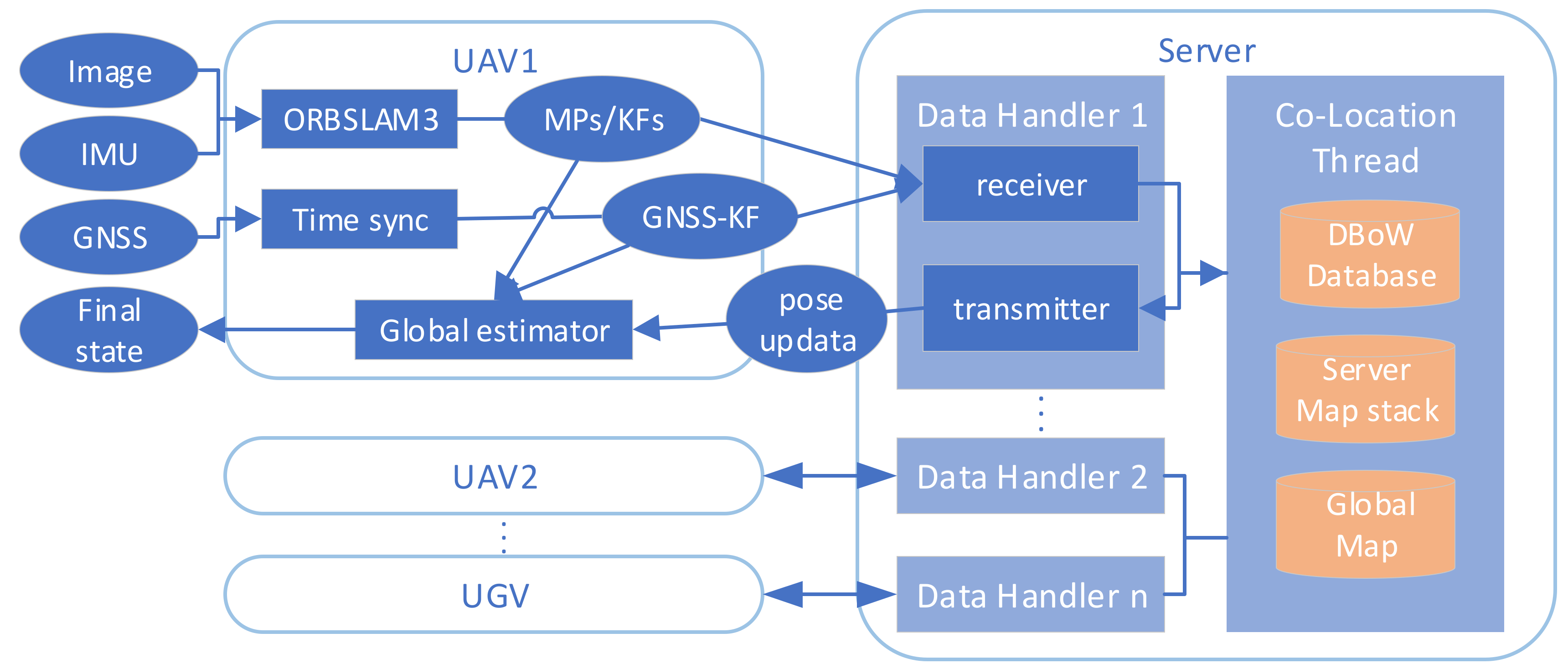
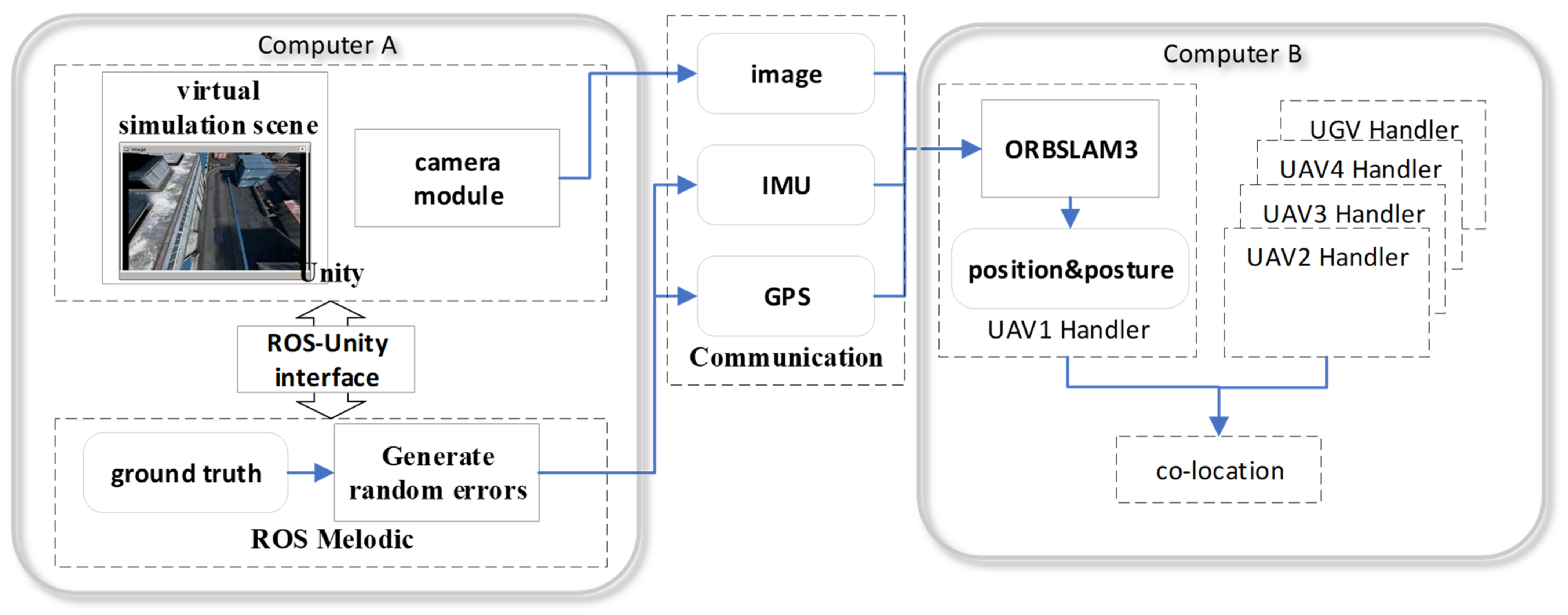
The architecture of the framework is depicted in Figure 1. At the early stages of system startup, all the UAV take off from a platform on the top of a UGV. After the unmanned platform completes IMU initialization and performs the first global bundle adjustment (BA), map fusion and relative pose solutions are completed between unmanned platforms through the local map. A flowchart of the co-location program executed on the server is shown below:
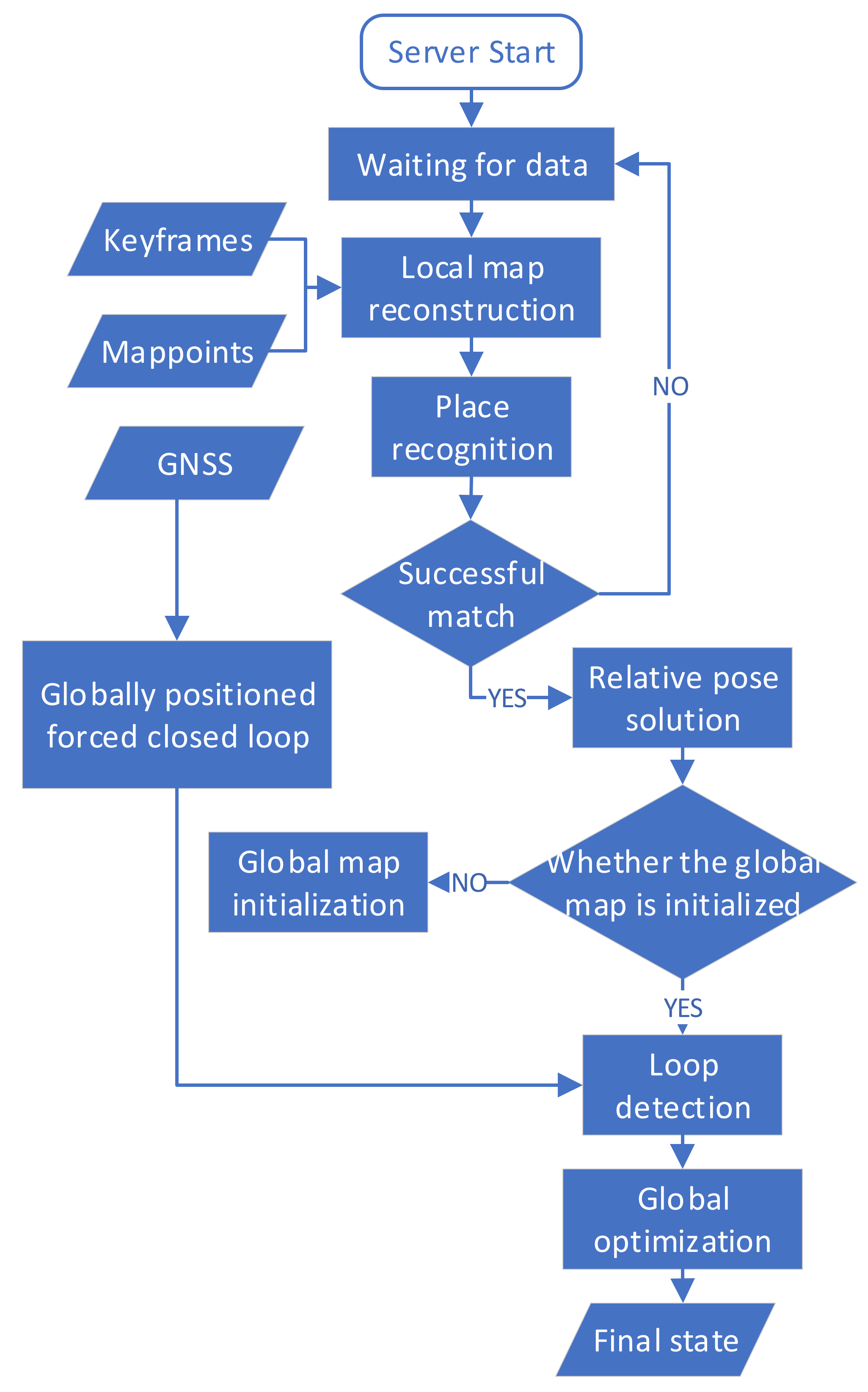
For convenience of explanation, the first stage of the position estimation coordinate system for a single platform is called the VIO frame. The coordinate system where each agent’s local map is located after a single platform has completed the second stage of position estimation is called the local frame. The coordinate system where the global map is located after map fusion is completed on the server is called the global frame. The co-location program on the server is shown in Figure 2. When there is no GNSS positioning or collaborative positioning information, the VIO frame will overlap with the local frame. The global frame overlaps with the local frame of the UGV before initialization, and the process of global map initialization is to obtain the relative positioning relation between each UAV and UGV through PnP solutions and convert the local map of each agent to a global map based on UGV’s local map. After initialization, the local frame of each agent will overlap with the global frame. As the unmanned platform continues to move, each agent generates a new keyframe during the local SLAM process and sends these new keyframes and map points to the server through wireless data communication. The server stack will cache map information from each agent. These keyframes and map points will be added to the global map through the initialized relative position changes between platforms. After the program discovers place recognition among platforms through detecting feature points, loop-closure and map fusion of the global map will be executed, as well as optimization. The optimized position and pose will be used to estimate that in the second stage, together with the GNSS positioning from each platform. Finally, the new pose of the new keyframes after collaborative positioning in the closed-loop position will be sent back to the corresponding agent. And the agent that accepts the collaborative positioning information will adjust their pose during the second stage of local optimization.

2.2. Keyframe-Based SLAM Algorithm Fusing GNSS Positioning Information and Co-Location Information

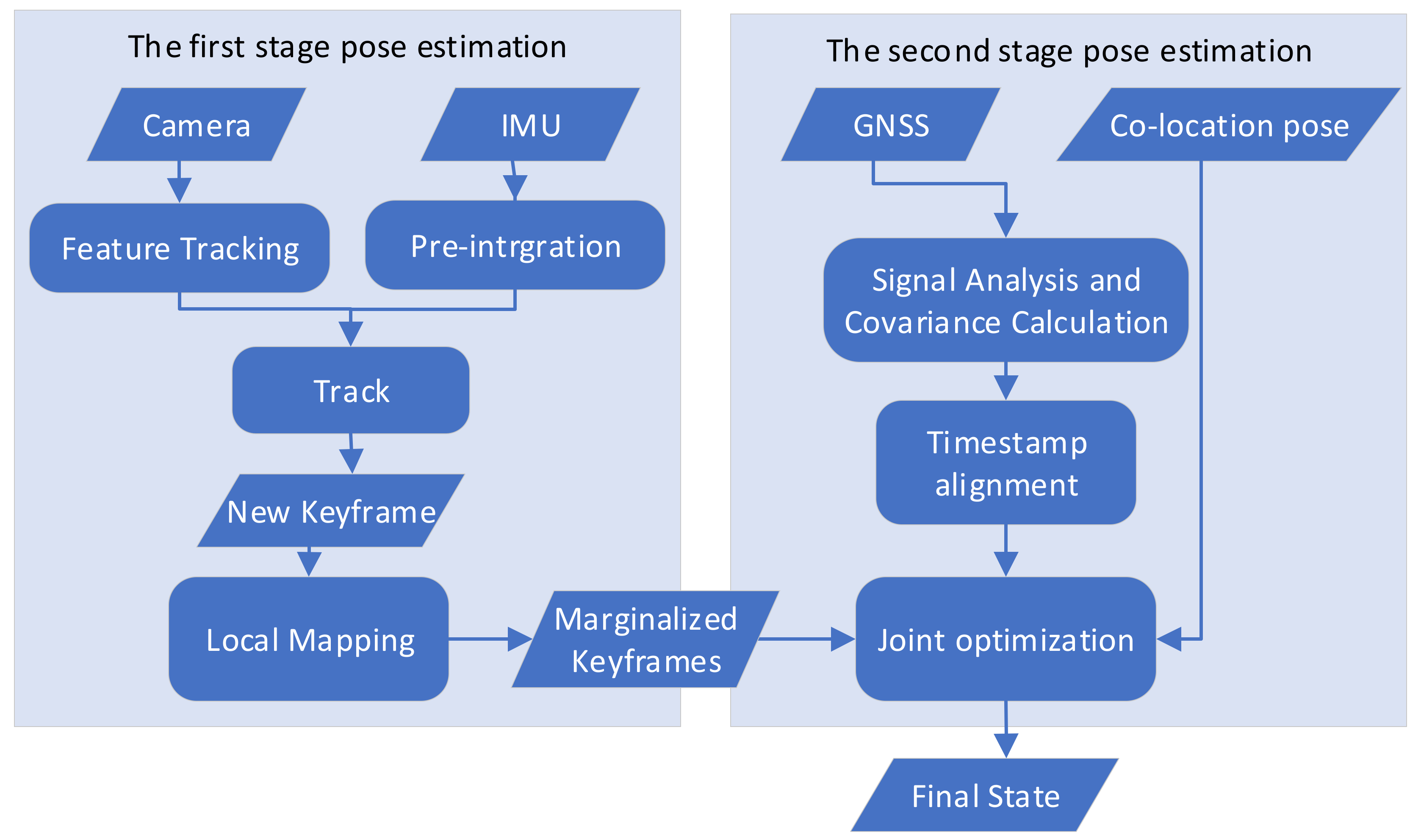
We deployed a SLAM framework modified and based on ORB-SLAM3 on each agent to run independently, to ensure each agent can complete independent navigation tasks in the situation where communication links are lost. The algorithm’s flow is shown in Figure 3. ORB-SLAM3 was modified as follows:
  • A communication module to the server was added to exchange keyframe and map point information with the server instantly. The details about this part will be introduced in Section 2.3.1;
  • The position estimation of the second stage was added, and both GNSS positioning information and collaborative positioning information were fused.
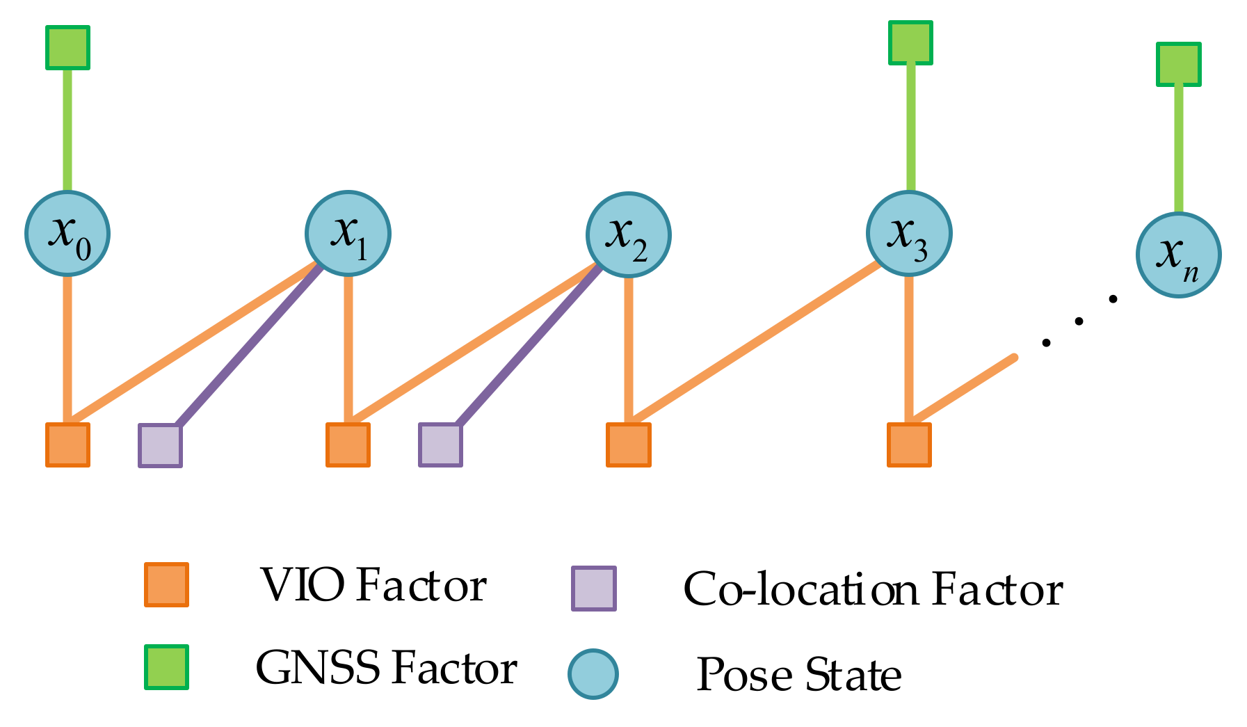
Each node represents a keyframe position and pose in the world frame. In Figure 4, the line between two nodes is called an “edge”, which represents the constraint of the amount to be optimized in the optimization of the factor graph. The edge between two consecutive nodes is a local constraint, which comes from ORB-SLAM3′s pose estimation. The other edge is the constraint from the co-location results of the server and GNSS satellite positioning information. We used the VIO factor as the local constraints, and GNSS location information and co-location information as global constraints. An illustration of the second-stage global pose graph structure is shown in Figure 4.
Construction of residuals with local constraints refer to ORBSLAM3 [1], supposing that there are two continuous keyframes K F t i and K F t j , we define q t v as the attitude quaternion K F t under the VIO coordinate system, and p t v as the three-dimensional coordinate under the VIO coordinate system of K F t . Similarly, q t l and p t l are the quaternion and coordinates under the global coordinate system. The VIO local factor is derived as:
z L s L ( χ ) = z L s L ( x t j , x t i ) = q t j v 1 P t i v P t j v q t j v 1 q t i v q t j l 1 P t i l P t j l q t j l 1 q t i l
where z is the measured value, provided by the results of the one-stage position estimation; χ is the state prediction; and s is the observation equation. χ is calculated from the pose transformation between the two moments. The specific method used in this paper uses the relative pose of the current moment and the previous moment obtained from the position estimation in the first stage to add to the position coordinate x t j at the previous moment to obtain the position coordinate x t i at the current moment. is the minus operation on the error state of quaternion. We take the pose covariance matrix generated during SLAM as the covariance of local measurements. The essence of the local factor is the relative change in the pose in two keyframes.
Consider the following two situations where GNSS does not work: the GNSS signal is poor or has interference, resulting in a large error in the GNSS positioning information, resulting in a large drift in an agent’s navigation trajectory; the GNSS signal is completely disabled, and there is no GNSS positioning information. Upon receipt of a valid GNSS location, the longitudinal dimension heights of the original measurements will be transformed into x, y, z coordinates in the local Cartesian coordinates system (ENU) during GNSS data preprocessing. P t G = [ x t w , y t w , z t w ] T is the coordinate of the GNSS information in the transformed ENU coordinate system. P t G is the measured value of GNSS at that moment, t . The uncertainty of measurement is assumed to be a Gaussian distribution with mean and covariance. P t w is the assumed GNSS estimate. The GNSS factor is derived as:
z t G s t G ( χ ) = z t G s t G ( x t ) = P t G P t w
When each agent receives a new pose about a keyframe’s collaborative positioning from the server, we introduce the result of collaborative positioning as a new measured value into the process of secondary optimization. We assume that the result obtained by K F t in the first-stage pose estimation at that moment in the VIO coordinate system is q v , p v . The pose obtained by K F t after the co-location is transformed into q c , p c on the local framework of the agent. The co-location factor is derived as:
z t C s t C ( χ ) = z t C s t C ( x t ) = q v l 1 P c l P v l q v l 1 q c l q v w 1 P c w P v w q v w 1 q c w
Lastly, in order to prevent VIO from drifting too much, the transformation of the VIO coordinate system to the global coordinate system should be updated after each optimization. The operation must make the position after fusion overlap with the results of GNSS positioning and cooperative positioning as much as possible, and the difference between the two frames should be as equal as possible with VIO. The data from VIO does not impose constraints on the absolute position after fusion, and only requires that the incremental error of the position after fusion and the incremental error of VIO should be as small as possible.

2.3. Communication

The communication modules on the agents and server was based on The ROS communication infrastructure [21]. It was used for message passing over a wireless network. The communication interface supports two-way communication between the agents and the server, we applied it to update the keyframe pose at a given moment for single-platform SLAM. The server uses it to receive map information from each agent. With this module, the objects waiting to be sent were first serialized/deserialized. Since ROS is not a real-time communication system, time stamps needed to be attached to packets.

2.3.1. Agent-to-Server Communication

In order to realize map data sharing from agent to server and save data bandwidth as much as possible, we added several state variables into the ORB-SLAM3 program to monitor the running status of SLAM on a single platform, including: IMU initialization process, whether visual-inertial bundle adjustment (VIBA) is completed, and tracking the running status of threads. After the IMU completes initialization and VIBA, all the previous keyframes and map point information is serialized and sent. The keyframe information includes the unique ID of this keyframe on the agent, its pose and time stamp, the information of feature points it contains, and the numbers of all map points observed by this keyframe. The map point information contains the ID of this map point on the agent, its three-dimensional coordinates, its descriptors, and the ID of all keyframes that have observed this map point so far. Unique IDs ensure that these messages are not sent repeatedly to reduce the required network bandwidth. The communication module distinguishes between dynamic information (such as the pose of a keyframe that may be adjusted according to the running state of SLAM) and static information (descriptors of feature points). In the process of communicating with the server, each agent will send the smallest packet at the highest frequency (including at least one newly added keyframe information).

2.3.2. Server-to-Agent Communication

Each agent handler thread is responsible for processing keyframes and map points from the corresponding agent on the server. Each keyframe is not processed until all of its observed map points have been deserialized by an agent handler and inserted into the map stack. The server map stack contains separate maps that contain data from each agent. When the server maps complete location identification and merge, the two maps are removed from the map stack and replaced with their merged map until there is only one global map in the entire server map stack. When the server detects the new closed-loop and completes the global pose optimization, it sends the ID and pose of the keyframe back to the corresponding agent to be updated.

2.4. Global Map Initialization and Intra-Agent Measurements

In order to enable the system to complete the positioning of each agent without GNSS at the initial stage of operation, we let the UAVs and UGVs start from the same position with the same angle of view. In this paper, UAVs are set to take off from the top platform of the UGV. After the IMU initialization is completed (which commonly needs 15–35 keyframes and takes 5–10 s), the agents perform a visual-inertial bundle adjustment. The aim of this action is to improve the precision of the initial map. Then, each agent sends its initial optimized local map to the server. For a certain terminal A g e n t c , the server will start the alignment from the keyframe K F c at the most recent moment sent in the M a p c . First, a subset of maps M a p m from the server map stack and brute-force descriptors are chosen that match all keyframes contained within that map with K F t c through DBoW2, and obtained the most likely matched candidate K F t 1 m , K F t 2 m K F t i m (We set i to four times that of the number of agents). For each keyframe, among all the feature points contained in it and its five best common-view keyframes, the 2D-2D feature point matching provided by DBoW2 is used to obtain the 3D-3D matching between their corresponding map points. The map points of candidacy K F t n m will be converted to K F t c through T c m n . If the reprojection error is less than the threshold, a vote is cast for the corresponding K F t n m , and the frame with the most votes is selected as the matching frame. For further improvement of the closed-loop’s robustness, the matching frame and its common-view frame together need to achieve three successful matches to be considered as the complete place recognition. If, at this moment, A g e n t c is a UAV, A g e n t m is a UGV, then the UAV’s local map will be fused into the UGV’s through T U A V c _ U G V m = T c m . If both A g e n t c and A g e n t m are UAVs, the relative pose transformation will be saved until one of them is fused with the UGV’s map, and another will complete fusion through T U A V c _ U A V m × T U A V m _ U G V . After the above pairwise pairing of the unmanned platforms, the local map of each UAV is finally converted into the coordinate system of the local map of the unmanned vehicle. New incremental keyframes and map points received by the server during subsequent operations will be transferred to the global map with the corresponding poses until a new loop closure or GNSS location provides a new location constraint.

2.5. Loop Closure and Global Optimization

The place recognition of loop closure is similar to the global map initialization, which depends on the feature point matching provided by DBoW2, and the initial matching through RANSAC and the PnP algorithm. Different from the global map initialization, considering the long-term drift of single-platform SLAM, a finer relative position transition is required. As above, we suppose that K F c of A g e n t c and K F m of K F m have complete initial matching and T c m = R t 0 1 S E 3 . All converted map points contained within the common-view frame of K F m , and those found matching to the key points in K F c . After the above intra-agent measurements have been completed, we need to adjust the map information according to the new closed-loop and fuse all the positioning information from each agent to perform global optimization. The details are as follows.

2.5.1. Refinement of Transformation Matrix

T c m is used to convert all map points contained within the common-view keyframe of K F m , and matching map points are located in the feature points of K F c . To obtain as many matches as possible, the map points are found that matches K F c in K F m and all of its keyframes at the same time. The nonlinear optimization of T c m = s R t 0 1 s i m 3 is carried out by using all the map point matching relationships found (the initial value of s is 1), and the goal function is the bidirectional reprojection error

2.5.2. Pose Graph Optimization

After obtaining the optimized transformation matrix T c m , the redundant map points need to be eliminated in the above matching process for each pair of matching map points describing the same feature point. Then propagation of the corrections must be disseminated to the rest of the map through pose graph optimization. To eliminate duplicate points, for each pair of matches the points from A g e n t c are removed, and the points from A g e n t m inherit all the observations of the removed points. By adding edges to the co-visibility and essential graphs, the observability is propagating between the common-view frames of K F m and K F m .
As it has sufficient computing power on the server and is not sensitive to the time cost, global BA optimization can be directly carried out on the adjusted visibility and essential graphs.

2.5.3. Global the Second-Stage Pose Estimation

The factor graph structure of the global two-stage optimization is similar to that of the single platform, the difference is that in the global optimization process only the GNSS positioning information (if any) is needed to be taken into consideration. This is due to the GNSS positioning information from different agents will also generate new position constraints on the global map making the track change significantly and intersect, even if there is no visual re-location at that position. In this case, we would lower the threshold in line with the RANSAC algorithm. If it can pass the detection after reducing the number of inner points, a new closed-loop will be established here. The subsequent processing is consistent with the closed-loop process described above.

3. Simulation and Experimental Result

3.1. Virtual Simulation Experiment Platform

The overall architecture of the multi-unmanned platform simulation system based on Unity3D and ROS architecture is shown in Figure 5. The UAV flight control and visual simulation is based on Flightmare [22]. The ROS Gazebo [23] simulation environment was run on Computer A to constrain the movements of UAVs and UGVs through dynamic models, and to generate the true values of the position and motion velocity. Position and velocity errors were superimposed to generate virtual IMU and GNSS data. Among them, GPS positioning information in GPGGA format was chosen as GNSS satellite positioning. The location and timestamp of an agent sent to the visual simulation module was passed through ROS-Unity3D interface. The visual simulation module moves the agent’s model to the corresponding coordinates, renders the photo, and finally sends the most up-to-date image and timestamp to the algorithm verification program on Computer B. The configuration of the two computers in the figure is shown in the Table 1.

3.1.1. Engine Dynamics Modeling and Simulation for a Type of UAV and UGV

The rigid body appearance, physical properties, joint types and other aspects of the unmanned platform are described through URDF files. The motion of the unmanned platform model in the ROS environment can be viewed through Gazebo. Its position in Gazebo is taken as the true value of the pose of the unmanned platform. hybrid A* algorithm to UGV is applied to realize the path planning, and TEB algorithm to realize trajectory tracking. The UAV adopts a four-rotor model, using the quadrotor dynamics to design the control algorithm, and the Euler method and fourth-order Runge-Kutta method to integrate the UAV dynamics equation.

3.1.2. Visual Simulation Based on Unity3D

The visual simulation module includes scene resources and unmanned platform models. The scene resource module is responsible for the construction and optimization of 3D scenes in the visual simulation software, and makes the scenes restore the real environment as much as possible to run smoothly through the 3D model import and level of detail (LOD) optimization. Multiple unmanned platforms can be loaded in the simulation scene according to the demand, and the objects can be driven to move according to the immediate feedback of the data in ROS. Particle effect components are used to simulate weather, such as rain and fog. The light was set in the Unity scene to simulate a sunny day, dusk and night. Various meteorological and light environments were combined to simulate different visibilities in the real world. Lastly, the virtual RGB images were obtained through the Unity camera module.

3.1.3. Virtual Sensor Data Generation

Based on the modeling of the unmanned platform in Section 3.1.2, two sensor components were added: an inertial measurement unit module and a GPS module. IMU and GPS data were obtained by adding noise to the true value of the sensor model in the Gazebo coordinate system. The IMU-related parameters are shown in Table 2:
The parameters related to GPS are shown in Table 3.

3.2. Experimental Results

This section introduces the simulation and experimental results of the autonomous positioning in an unknown environment by using the heterogeneous UAV and UGV system proposed. In the following experiment, we generated specified waypoints for the three UAVs and a UGV through the virtual simulation and saved the resulting sensor data and time stamps in the ROS bag for subsequent repeating tests. We examined the robustness of the method we proposed in an actual engineering scenario by modifying the ambient light, weather in the scene, and the down view angle of the UAV camera. Then we analyzed and compared the influence of the collaborative positioning framework on the positioning accuracy of each platform with single-platform positioning. The detailed settings for each dataset are shown in the Table 4.

3.2.1. The Influence of External Factors on the Function of Algorithm Framework

Our algorithm depends on visual graph feature points to complete place recognition, which is the foundation of subsequent map fusion and loop closure. Considering that visual angle difference and observation conditions are the main factors affecting feature point matching, we set three meteorological environments in the virtual simulation system: no occlusion, mist and fog, and two lighting environments: normal light and high light ratio under sunset. There was no cover, mist and fog representing the visibility of infinity, 150 m and 50 m, respectively. A schematic of the scenario is shown in Figure 6.
The first thing worth paying attention to is the network bandwidth occupied by each agent and server for exchanging data in the virtual communication network environment. In Table 5, we list the average bandwidth and instantaneous traffic peaks of upload and downlink data between each agent and server. The peak of uploaded data occurs during map initialization, and the bandwidth usage is relatively smooth thereafter. There is a positive correlation between bandwidth usage and keyframe generation speed.
Here, we compared the number of closed-loops generated with that of the feature points matched on the closed-loop frame during the operation process of the collaborative positioning algorithm on different datasets. From the results in Table 6, we found that the feature point matching had similar performance under two similar viewing angles when the viewing angle of UAV was the same. As many feature point pairs as possible are beneficial not only to achieve robust place recognition, but also to improve the positioning accuracy of SLAM. However, the number of feature point matching between UAV and UGV will decrease with an increase in the angle of view difference, which is more obvious when a UAV flies at low altitude. We believe that setting the camera angle of the UAV to 45° in the downward view can balance the need for visual repositioning among UAVs and between UAVs and UGVs better.
As can be seen from the data in Table 7, the change of light affected the detection of feature points, but the number of feature points in the picture was still enough to produce the correct closed-loop. In the mist mode, 59% of feature point pairs were lost, and the number of correct closed-loops produced also dropped dramatically. Moreover, dense fog interfered the feature point detection and place recognition thoroughly. In the dense fog mode, except when the map initialization was completed when all the UAVs and UGVs started from the same position at the first stage of the operation, all the position re-identifications failed at the position where the closed-loop should be generated due to insufficient matching feature points in subsequent operations.

3.2.2. Collaborative SLAM Estimation Accuracy

To estimate the positioning accuracy of the system, in this section the influence of external observation conditions on the experiment results were ignored and the camera view that generated the largest average number of matching point pairs (45°) was adopted. The experiment for this section was run on Factory 01, 03, 05, 06 on the datasets described in Table 8.
We estimated the absolute trajectory error (ATE) of each agent. We tested the positioning performance in GPS-denied and GPS-challenged modes separately. In the GPS-challenged 1 mode, all agents obtained valid GPS location information every 20 s. In the GPS-challenged 2 mode, the UAV could only randomly obtain four valid GPS positions during the operation, and the UGV masked all GPS location information. In the GPS-denied mode, all agents would not use the GPS location data in the dataset. The effect trajectory of the three UAVs and the unmanned vehicle in the collaborative positioning is shown in Figure 7a.

4. Discussion

From the experiments described in Section 3 we draw the following three conclusions.
  • Experiments in the virtual simulation platform demonstrated that the co-location framework we designed can maintain usable positioning accuracy over hundreds of meters of trajectory when the GNSS signal is rejected. At the same time, the co-location framework outperforms the single platform in terms of accuracy. This is essentially attributed to the new position constraints arising from place recognition between the different platforms.
  • The SLAM front-ends we currently employ were not sufficiently stable under poor observation conditions. For example, poor visibility environments or poor near-orthogonal viewing angles affected the proper function and positioning accuracy of the air-ground co-location system. The main reason is that the ORB feature-based SLAM front-end we adopted often cannot provide a sufficient number of feature points for matching to achieve robust location re-identification. Other common front-end methods, such as optical flow method, have more stringent requirements on observation conditions and viewing angles. In the SLAM front-end process, if the threshold of hamming distance for ORB detection is lowered in order to increase the number of matched pairs, it will lead to excessive false matches affecting the accuracy of VIO. Therefore, place recognition that relies on ORB features can only be adapted to the images generated under more optimum observation conditions. The visual front-end used in this manuscript fulfills the basic requirements for cooperative air-ground localization but is not yet sufficiently robust for weak observation conditions.
  • The method described in this manuscript allows the location information of each agent in the entire unmanned cluster to be propagated to the other agents in the cluster. This process improves the positioning accuracy while also allowing the server and the individual unmanned platforms to acquire relative positions to each other. We designed a comparison of four cases. They were GPS-challenged co-location, GPS-denied co-location, single-platform independent operation of ORBSLAM3, and single-platform independent operation of ORBSLAM3 fusion GPS. In GPS-denied mode, the simulation was performed on a solar body with no GNSS fix except of Earth, or on Earth but the GNSS signal had interference. In this case, the positioning of each agent completely depended on the camera and IMU. It can be seen from Table 8 that the accuracy of co-location was significantly improved compared with the positioning accuracy of ORBSLAM3 running on a single platform. Assuming that some agents in the system obtained satellite positioning information, the positioning accuracy of all agents was improved. It is worth noting that even if we assume in the experiment that the UGV cannot obtain satellite positioning signals at all, its positioning accuracy still benefits from the co-location algorithm. This is due to the fact that the new constraints brought by the satellite positioning information are propagated to the local maps of all agents through the global map. Through the comparison of the two GPS-challenged modes, we found that only a few GPS points were enough to greatly improve the positioning accuracy. The GPS-challenged 1 mode used several times more GPS positioning points than the GPS-challenged 2 mode, but the positioning accuracy was not significantly improved compared with the latter.
In the experiments designed in this manuscript, we set the UAV to use high-precision GNSS positioning information, while the UGV could not obtain GNSS signals. There were two main reasons for this assumption. The first point was that, in practice, UAVs located in the sky can often obtain GNSS positions with good accuracy through RTK or relative positioning measurements. Whereas vehicles located on the ground may temporarily lose their GNSS position due to obstruction by reinforced concrete buildings, or by entering tunnels and interiors. The second point was that ORBSLAM3 itself is an excellent single-platform SLAM algorithm, which can have a trajectory drift error of less than 1% with a closed-loop bottleneck. This makes it difficult for the meter-level errors inherent in GNSS to contribute to the improvement in positioning accuracy if differential-free GNSS positioning is used in a virtual scene of limited size. If the scale of the motion trajectory reaches several kilometers, however, even differential-free GNSS positioning information can greatly optimize the positioning accuracy.
In our paper, we focused on collaborative localization. However, in engineering applications, the movement of each agent in the system was not infinite due to the limitation of communication bandwidth and communication distance. Due to the lack of prior information of the global map, the pose information of each agent and the local map information received by the server had time delays, and the global positioning pose updated through the visual closed-loop had no gradient information. In this case, if a motion strategy for convex online learning to train unmanned clusters is required, delayed mirror descent (DMD) [24] would be a good choice. We will use this approach in the subsequent work. In the aspect of multi-agent motion control, our method only used the most basic D* Lite algorithm. Only the trajectory of a single agent was considered to fit the route generated in advance. However, in practical applications, there may be obstacles in the waypoints planned in advance, and the route itself is unreachable. Cooperation among multiple agents can be difficult to achieve. Collaborative algorithms such as [25] realize the decentralized and real-time cooperative pursuit of a single evader in the planar domain. By improving the method proposed in this paper, the control of the prior map obtained by the UAV would be improved.
Finally, it is worth mentioning that in the statistics of network bandwidth usage, we found that the peak bandwidth usage occurs in the map initialization phase, which is about three times the average value. In the case of long distance or interference, this will put higher requirements on the performance of wireless communication devices. When there is a prior map, it will greatly relieve the bandwidth pressure during system initialization. During system initialization, at least four high-quality GNSS positioning points are needed to convert the VIO coordinate system to the northeast sky coordinate system. Meanwhile, ORBSLAM3′s IMU initialization requires initial zero-bias estimation and gravity direction estimation to obtain scale information, which makes the initialization of the global map take too long. How to complete global map initialization more efficiently and quickly or to make better use of prior map information is the next urgent problem to be solved.

5. Conclusions

This manuscript uses ORB-based feature point re-identification to improve the positioning accuracy of all unmanned platforms in a cluster by fusing the local maps of each unmanned platform with new position constraints and global GNSS positioning information. Through a centralized collaborative positioning service, this can provide low latency positioning information for subsequent collaborative path planning and task allocation algorithms. The co-location algorithm proposed in this manuscript has better accuracy in both GNSS-challenged and GNSS-denied modes than the ORB-SLAM3 algorithm running on a single platform. The two-stage position estimation method used can also be combined with other positioning sensors such as UWBs and barometers in addition to the GNSS global positioning information applied in the manuscript. Current techniques for the localization of air-ground unmanned clusters in complex environments present new demands in the direction of visual front-ends, optimization methods and multi-sensor fusion. The approach proposed in this manuscript can be extended to other unmanned clusters in areas such as UAVs, logistics, agriculture and military. In the future, based on the current results, our subsequent work will further investigate the impact of different vision front-end techniques on location re-identification, a key aspect that critically affects map fusion and closed-loop detection. We will consider the use of feature detection and matching techniques based on deep learning or point and line features to improve the robustness of the algorithmic framework and to improve the localization accuracy based on this. Finally, our proposed approach in this manuscript has high computational resource requirements for map fusion and global optimization, and we will aim to mitigate the computational power and communication bandwidth required for global map maintenance on a server.

Author Contributions

Conceptualization, H.X.; methodology, H.X.; software, H.X.; validation, Y.L. and S.Y.; formal analysis, C.W.; resources, Y.B.; data curation, C.W.; writing—original draft preparation, H.X.; writing—review and editing, C.J.; visualization, W.L.; supervision, W.L.; project administration, Y.B. All authors have read and agreed to the published version of the manuscript.

Funding

This research received no external funding.

Data Availability Statement

Not applicable.

Conflicts of Interest

The authors declare no conflict of interest.

References

  1. Mourikis, A.I.; Roumeliotis, S.I. A multi-state constraint kalman filter for vision-aided inertial navigation. In Proceedings of the IEEE International Conference on Robotics and Automation, Orlando, FL, USA, 15–19 May 2006; pp. 456–478. [Google Scholar]
  2. Campos, C.; Elvira, R.; Rodriguez, J.J.G.; Montiel, J.M.M.; Tardos, J.D. ORB-SLAM3: An Accurate Open-Source Library for Visual, Visual–Inertial, and Multimap SLAM. IEEE Trans. Robot. 2021, 37, 1874–1890. [Google Scholar] [CrossRef]
  3. Elvira, R.; Tardos, J.D.; Montiel, J. ORBSLAM-Atlas: A robust and accurate multi-map system. arXiv 2019, arXiv:1908.11585. [Google Scholar]
  4. Cadena, C.; Galvez-López, D.; Tardos, J.D.; Neira, J. Robust Place Recognition with Stereo Sequences. IEEE Trans. Robot. 2012, 28, 871–885. [Google Scholar] [CrossRef]
  5. Pumarola, A.; Vakhitov, A.; Agudo, A.; Sanfeliu, A.; Moreno-Noguer, F. PL-SLAM: Real-time monocular visual SLAM with points and lines. In Proceedings of the 2017 IEEE International Conference on Robotics and Automation (ICRA), Singapore, 29 May–3 June 2017; pp. 4503–4508. [Google Scholar]
  6. Tian, Y.; Khosoussi, K.; How, J.P. A resource-aware approach to collaborative loop-closure detection with provable performance guarantees. Int. J. Robot. Res. 2021, 40, 1212–1233. [Google Scholar] [CrossRef]
  7. Giamou, M.; Khosoussi, K.; How, J.P. Talk Resource-Efficiently to Me: Optimal Communication Planning for Distributed Loop Closure Detection. In Proceedings of the 2018 IEEE International Conference on Robotics and Automation (ICRA), Brisbane, Australia, 21–25 May 2018; pp. 3841–3848. [Google Scholar]
  8. Cieslewski, T.; Scaramuzza, D. Efficient Decentralized Visual Place Recognition Using a Distributed Inverted Index. IEEE Robot. Autom. Lett. 2017, 2, 640–647. [Google Scholar] [CrossRef] [Green Version]
  9. Chang, Y.; Tian, Y.; How, J.P.; Carlone, L. Kimera-Multi: A System for Distributed Multi-Robot Metric-Semantic Simultaneous Localization and Mapping. In Proceedings of the 2021 IEEE International Conference on Robotics and Automation (ICRA), Xi’an, China, 30 May–5 June 2021; pp. 11210–11218. [Google Scholar]
  10. Lajoie, P.-Y.; Ramtoula, B.; Chang, Y.; Carlone, L.; Beltrame, G. DOOR-SLAM: Distributed, Online, and Outlier Resilient SLAM for Robotic Teams. IEEE Robot. Autom. Lett. 2020, 5, 1656–1663. [Google Scholar] [CrossRef] [Green Version]
  11. Choudhary, S.; Carlone, L.; Nieto-Granda, C.; Rogers, J.; Christensen, H.I.; Dellaert, F. Distributed mapping with privacy and communication constraints: Lightweight algorithms and object-based models. Int. J. Robot. Res. 2017, 36, 1286–1311. [Google Scholar] [CrossRef]
  12. Zou, D.; Tan, P. Coslam: Collaborative visual slam in dynamic environments. IEEE Trans. Pattern Anal. Mach. Intell. 2012, 35, 354–366. [Google Scholar] [CrossRef] [PubMed]
  13. Schmuck, P.; Chli, M. CCM-SLAM: Robust and efficient centralized collaborative monocular simultaneous localization and mapping for robotic teams. J. Field Robot. 2019, 36, 763–781. [Google Scholar] [CrossRef] [Green Version]
  14. Karrer, M.; Schmuck, P.; Chli, M. CVI-SLAM—Collaborative visual-inertial SLAM. IEEE Robot. Autom. Lett. 2018, 3, 2762–2769. [Google Scholar] [CrossRef] [Green Version]
  15. Liu, J.; Liu, R.; Chen, K.; Zhang, J.; Guo, D. Collaborative Visual Inertial SLAM for Multiple Smart Phones. In Proceedings of the 2021 IEEE International Conference on Robotics and Automation (ICRA), Xi’an, China, 30 May–5 June 2021; pp. 11553–11559. [Google Scholar]
  16. Schmuck, P.; Ziegler, T.; Karrer, M.; Perraudin, J.; Chli, M. COVINS: Visual-Inertial SLAM for Centralized Collaboration. In Proceedings of the 2021 IEEE International Symposium on Mixed and Augmented Reality Adjunct (ISMAR-Adjunct), Bari, Italy, 4–8 October 2021; pp. 171–176. [Google Scholar]
  17. Moafipoor, S.; Bock, L.; Fayman, J.A.; Conroy, E. Vision-Based Collaborative Navigation for UAV-UGV-Dismounted Units in GPS Challenged Environments. In Proceedings of the 33rd International Technical Meeting of the Satellite Division of the Institute of Navigation (ION GNSS+ 2020), Online, 22–25 September 2020; pp. 573–584. [Google Scholar]
  18. Fankhauser, P.; Bloesch, M.; Krüsi, P.; Diethelm, R.; Wermelinger, M.; Schneider, T.; Dymczyk, M.; Hutter, M.; Siegwart, R. Collaborative navigation for flying and walking robots. In Proceedings of the 2016 IEEE/RSJ International Conference on Intelligent Robots and Systems (IROS), Daejeon, Korea, 9–14 October 2016; pp. 2859–2866. [Google Scholar]
  19. Park, J.; Kim, P.; Cho, Y.K.; Kang, J. Framework for automated registration of UAV and UGV point clouds using local features in images. Autom. Constr. 2019, 98, 175–182. [Google Scholar] [CrossRef]
  20. Qin, H.; Meng, Z.; Meng, W.; Chen, X.; Sun, H.; Lin, F.; Ang, M.H. Autonomous Exploration and Mapping System Using Heterogeneous UAVs and UGVs in GPS-Denied Environments. IEEE Trans. Veh. Technol. 2019, 68, 1339–1350. [Google Scholar] [CrossRef]
  21. Quigley, M.; Conley, K.; Gerkey, B.; Faust, J.; Foote, T.; Leibs, J.; Ng, A.Y. ROS: An open-source Robot Operating System. In Proceedings of the ICRA Workshop on Open Source Software, Kobe, Japan, 12–17 May 2009; Volume 3, p. 5. [Google Scholar]
  22. Song, Y.; Naji, S.; Kaufmann, E.; Loquercio, A.; Scaramuzza, D. Flightmare: A flexible quadrotor simulator. arXiv 2020, arXiv:2009.00563. [Google Scholar]
  23. Koenig, N.; Howard, A. Design and use paradigms for gazebo, an open-source multi-robot simulator. In Proceedings of the 2004 IEEE/RSJ International Conference on Intelligent Robots and Systems (IROS), (IEEE Cat. No. 04CH37566). Sendai, Japan, 28 September–2 October 2004; Volume 3, pp. 2149–2154. [Google Scholar]
  24. Zhou, Z.; Mertikopoulos, P.; Bambos, N.; Glynn, P.W.; Tomlin, C. Countering feedback delays in multi-agent learning. Adv. Neural Inf. Process. Syst. 2017, 30. [Google Scholar]
  25. Zhou, Z.; Zhang, W.; Ding, J.; Huang, H.; Stipanović, D.M.; Tomlin, C.J. Cooperative pursuit with Voronoi partitions. Automatica 2016, 72, 64–72. [Google Scholar] [CrossRef]
Figure 1. Overall algorithm framework. “MPs/KFs” is short for map points and keyframes. In the figure, the oval block represents all kinds of data, and the square block represents the processing of data. Input for each platform includes images, IMU, and GNSS location information. Each data handler thread is responsible for handling a corresponding agent. Pose estimation and global optimization on a single platform and server are realized by factor graph optimization. Finally, the final state after global optimization is output to the subsequent program for path planning, task allocation or map construction.
Remotesensing 14 05055 g001
Figure 2. The running process of the co-location module in Figure 1 is explained in detail. The function of this module is to restore the received MPs/KFs data from each agent to a local map. The local map is further stitched into a global map through visual position re-identification, or a new closed-loop is added to the global map that has been initialized. Finally, the GNSS positioning information is integrated to perform global optimization and output the result of co-location.
Remotesensing 14 05055 g002
Figure 3. The tracking thread processes sensor information in real time and initially estimates the pose of the current frame. In the process of tracking the local map, the track thread determines whether the current frame is used as a keyframe. Different from ORBSLAM3′s keyframe addition strategy, when valid GNSS positioning information completes timestamp alignment, frames aligned with GNSS information are also inserted as keyframes.
Remotesensing 14 05055 g003
Figure 4. Schematic diagram of the pose graph structure to be optimized in the second stage. The circle is the state quantity, and the yellow square is the constraint of local observation, that is, the relative pose transformation of VIO from ORBSLAM3. The other colored squares are constrained by global observations.
Remotesensing 14 05055 g004
Figure 5. The virtual data generation program is deployed on Computer A, and the agent handler and cooperative location program is deployed on Computer B. They are connected using a gigabit network.
Remotesensing 14 05055 g005
Figure 6. Schematic diagram of the virtual simulation scene (a) bright scene with high visibility; (b) a dimly lit but fog-free scene; (c) foggy and dim scene. Different observation conditions will affect the extraction and matching of feature points.
Remotesensing 14 05055 g006
Figure 7. (a) The rendering of the co-location of three UAVs and a UGV; (be) trajectories and ground truth for a single-platform operation of each agent.
Remotesensing 14 05055 g007aRemotesensing 14 05055 g007b
Table 1. The hardware configuration of the computers running the virtual simulation platform and the positioning algorithm.
PlatformTypeCharacteristic
Computer ADesktop computerIntel9-11700k + 32 Gb + 2080Ti
Computer BDesktop computerAMD3990x + 64 Gb + 2080Ti
Table 2. IMU data production module parameter configuration table.
ParameterValue
Gyroscope noise density0.0003394 [Hz]
Gyro deviation random walk0.000038785 [Hz]
Gyro deviation related time constant1000.0 [s]
Gyroscope opening deviation standard deviation0.0087 [rad/s]
Accelerometer noise density0.004 [Hz]
Accelerometer deviation random walk0.006 [Hz]
Accelerometer deviation related time constant300.0 [s]
Update frequency100 [Hz]
Table 3. GPS data production module parameter configuration table.
ParameterValue
Standard deviation of Gaussian noise at horizontal position0.05 [m]
Standard deviation of Gaussian noise in vertical position0.15 [m]
Standard deviation of horizontal velocity Gaussian noise0.05 [m/s]
Standard deviation of vertical velocity Gaussian noise0.05 [m/s]
Update frequency5 [Hz]
Table 4. Parameter Settings for each dataset.
DatasetLighting ConditionsMeteorologyAgentCamera AnglePath Length
Factory 01brightHigh visibilityUAV145°162.47 m
UAV245°161.29 m
UAV345°168.96 m
UGV106.43 m
Factory 02brightthick-foggyUAV145°162.47 m
UAV245°161.29 m
UAV345°168.96 m
UGV106.43 m
Factory 03somberHigh visibilityUAV145°162.47 m
UAV245°161.29 m
UAV345°168.96 m
UGV106.43 m
Factory 04somberthick-foggyUAV145°162.47 m
UAV245°161.29 m
UAV345°168.96 m
UGV106.43 m
Factory 05brightmistUAV145°162.47 m
UAV245°161.29 m
UAV345°168.96 m
UGV106.43 m
Factory 06sombermistUAV145°162.47 m
UAV245°161.29 m
UAV345°168.96 m
UGV106.43 m
Factory 07brightHigh visibilityUAV125°162.47 m
UAV225°161.29 m
UAV325°168.96 m
UGV106.43 m
Factory 08brightHigh visibilityUAV125°162.47 m
UAV245°161.29 m
UAV375°168.96 m
UGV106.43 m
Table 5. This table shows the network bandwidth usage after all simulation datasets were run. The results are obtained from seven experiments.
AgentUploadDownlink
AverageMaximumAverageMaximum
UAV10.35 MB/s1.1 MB/s0.4 KB/s0.8 KB/s
UAV20.34 MB/s1.1 MB/s0.6 KB/s0.9 KB/s
UAV30.40 MB/s1.3 MB/s0.4 KB/s0.7 KB/s
UGV0.31 MB/s0.9 MB/s0.2 KB/s0.4 KB/s
Table 6. The number of feature points matching and successful location re-identification under different angles of view and illuminations.
Camera AngleLighting ConditionsNumber of Successful RelocationsAverage Number of Matching Point Pairs
25–25°bright28123.83
somber27.3110
45–45°bright27139
somber27113
75–75°bright28128.33
somber27129.5
25–75°bright536
somber435
25–45°bright1147
somber1044.83
45–75°bright1455.5
somber1149
0–25°bright1247
somber1042
0–45°bright1751.5
somber1738.83
0–75°bright423.33
somberFAIL18
Table 7. The number of feature points matching and successful location reidentification under different angles of view and illuminations.
Lighting ConditionsMeteorologyAverage Number of Successful RelocationsAverage Number of Matching Point Pairs
brighthigh visibility27125.83
mist1158
thick-foggyFAIL17.5
somberhigh visibility27112
mist739.83
thick-foggyFAIL15.33
Table 8. The accuracy of each agent running in different modes.
AgentModeATE_RMSE (m)/Mean Error (m)
UAV1GPS-challenged Co-location 10.262/0.170
GPS-challenged Co-location 20.311/0.197
GPS-Denied Co-location0.930/0.842
ORB-SLAM31.110/0.911
ORB-SLAM3 fusion GPS0.371/0.223
UAV2GPS-challenged Co-location 10.416/0.293
GPS-challenged Co-location 20.472/0.401
GPS-Denied Co-location1.298/1.025
ORB-SLAM31.523/1.465
ORB-SLAM3 fusion GPS0.488/0.317
UAV3GPS-challenged Co-location 10.368/0.273
GPS-challenged Co-location 20.397/0.285
GPS-Denied Co-location0.782/0.502
ORB-SLAM30.979/0.735
ORBSLAM3 fusion GPS0.396/0.299
UGVGPS-challenged Co-location 10.172/0.134
GPS-challenged Co-location 20.173/0.137
GPS-Denied Co-location0.219/0.171
ORB-SLAM30.405/0.297
ORB-SLAM3 fusion GPS0.186/0.175
Publisher’s Note: MDPI stays neutral with regard to jurisdictional claims in published maps and institutional affiliations.

