


An Improved Pedestrian Navigation Method Based on the Combination of Indoor Map Assistance and Adaptive Particle Filter

Abstract
1. Introduction
2. Materials and Methods
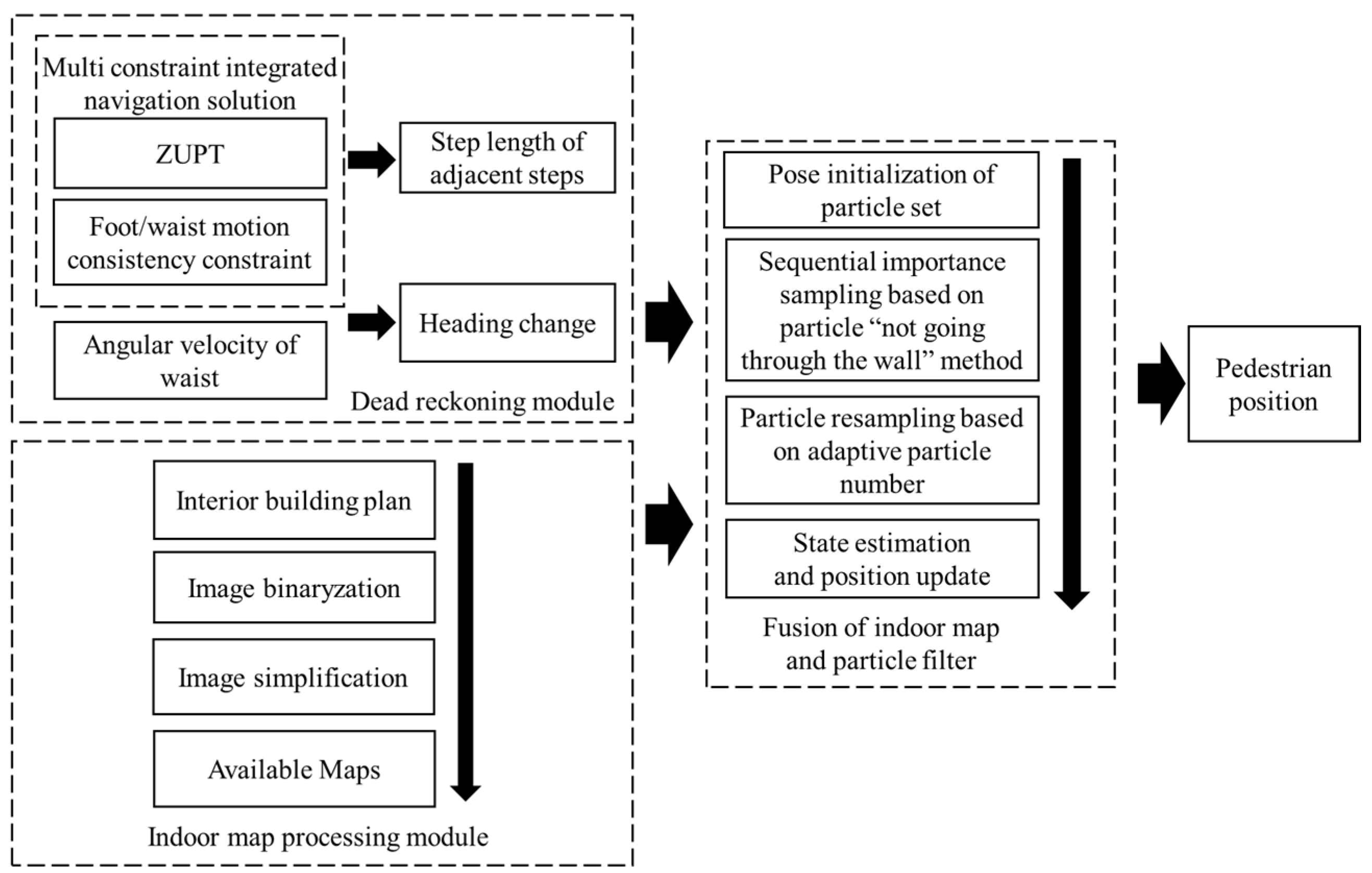
2.1. Proposed System Scheme
2.2. Pedestrian Navigation Method Based on Indoor MA and PF
2.2.1. Theoretical Model of Algorithm
- (1)
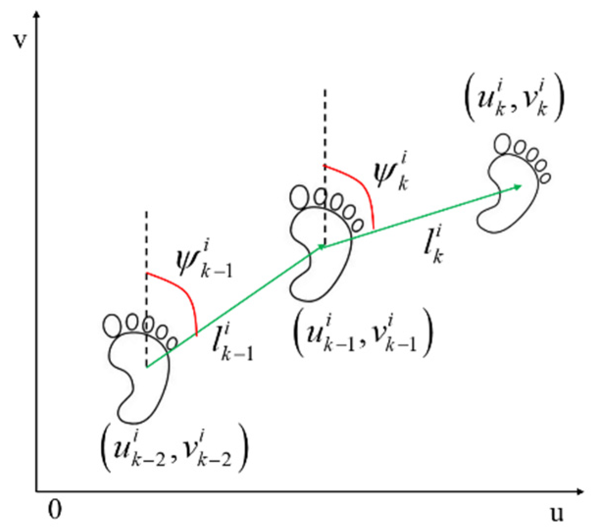
- Pedestrian navigation model based on dead reckoning
- (2)
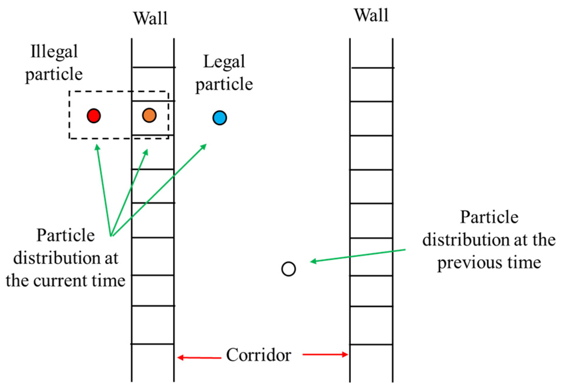
- Observation model based on particle “not going through the wall” method
2.2.2. Algorithm Process Design
- (1)
- Optimization of initial position and heading of particle set
- (2)
- One-step prediction of particle states
- (3)
- Particle weight updating based on prior map information
- (4)
- Particle resampling based on adaptive particle number
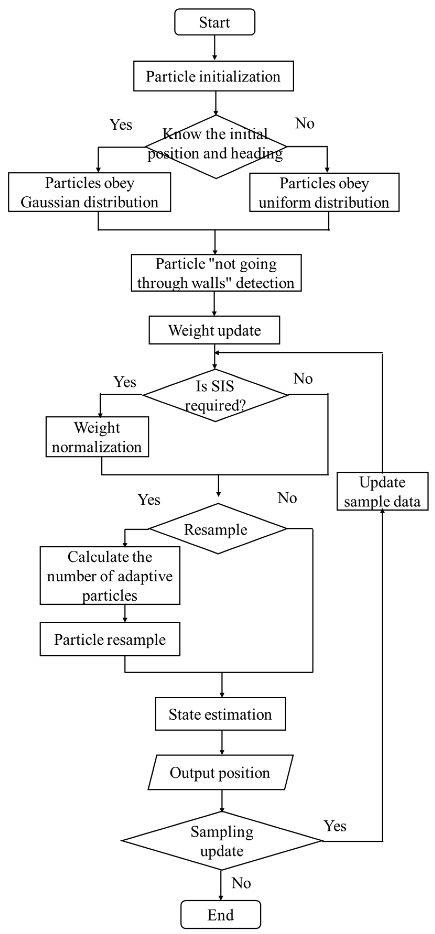
2.2.3. Algorithm Flow
3. Results
3.1. Verification of Simulation
3.1.1. Conditions of Simulation
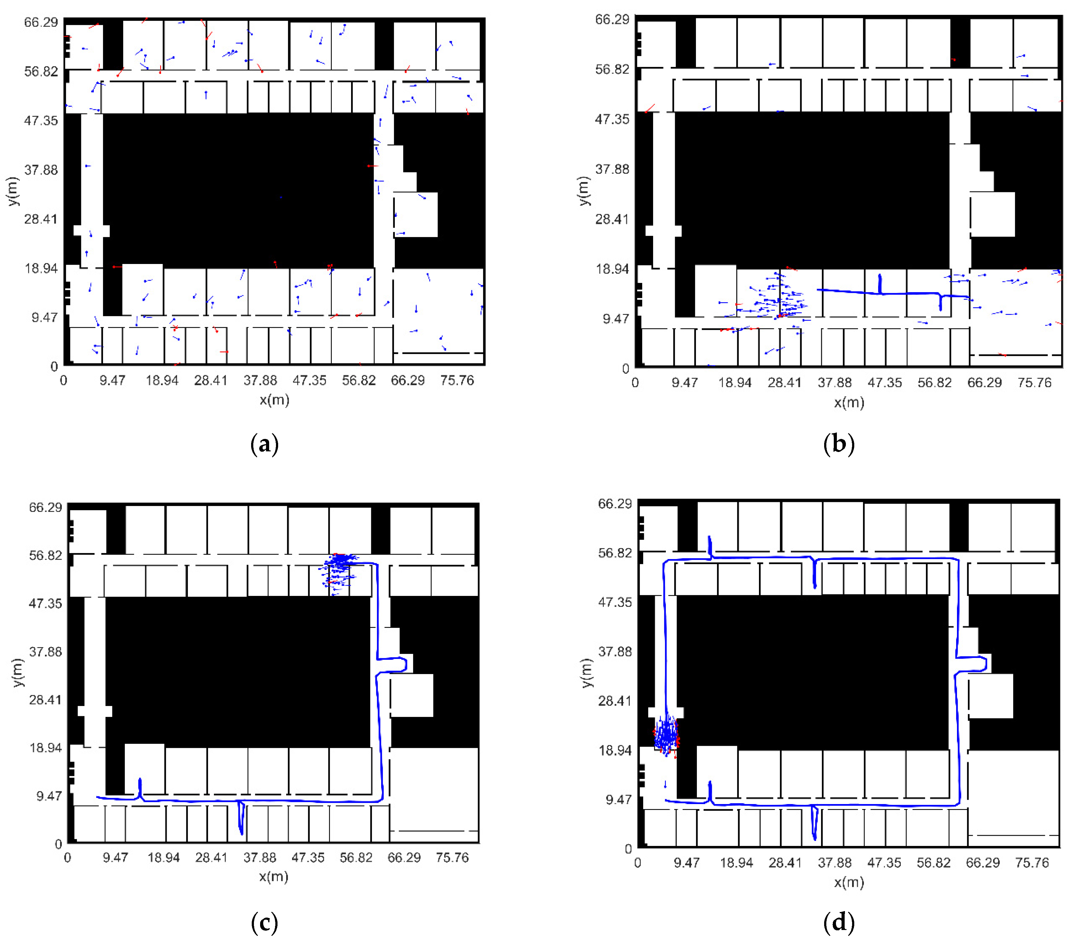
3.1.2. Analysis of Simulation Results
- (1)
- The initial position and heading of pedestrian are known
- (2)
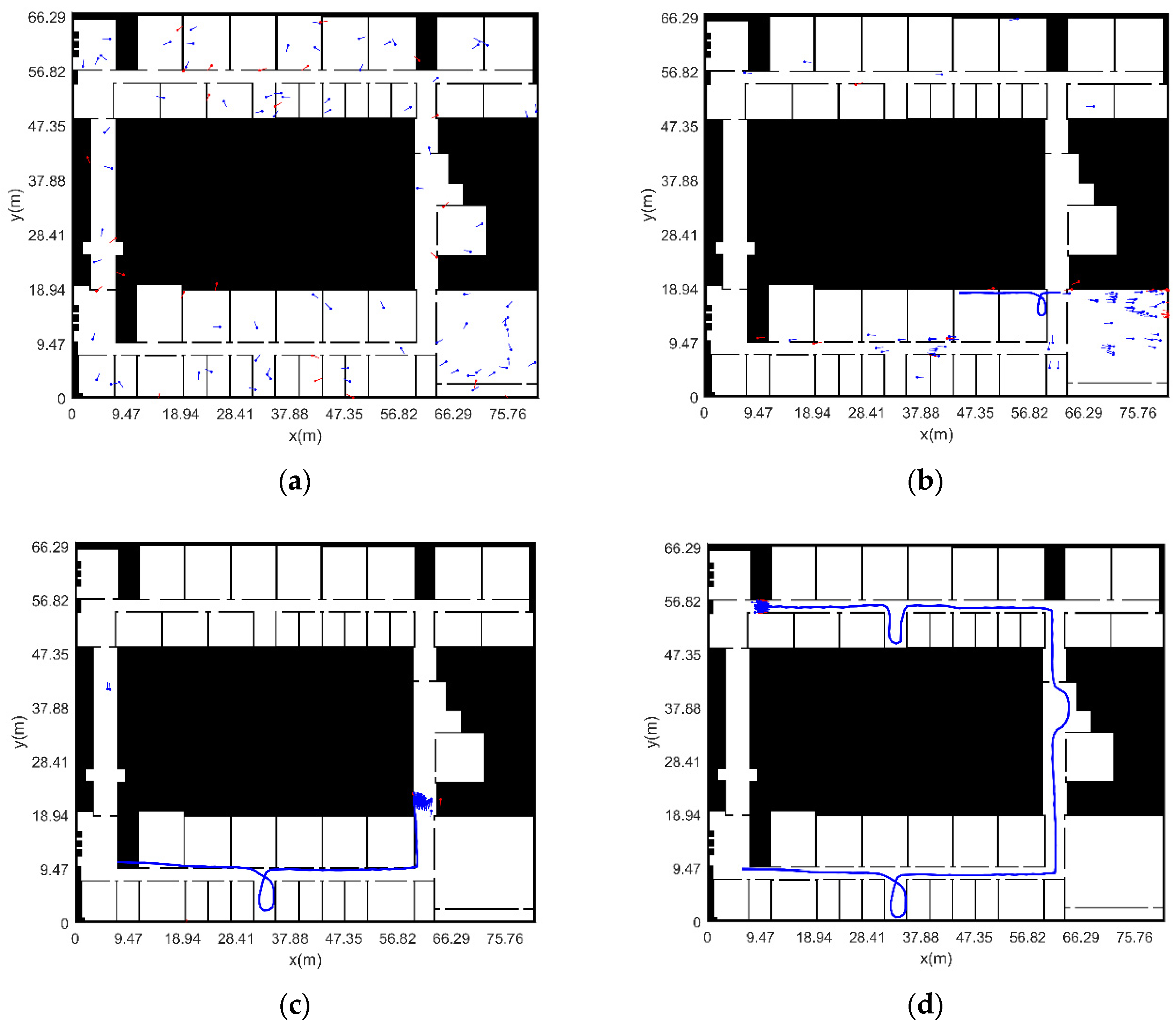
- The initial position and heading of pedestrian are unknown (adaptive particle number)
- (3)
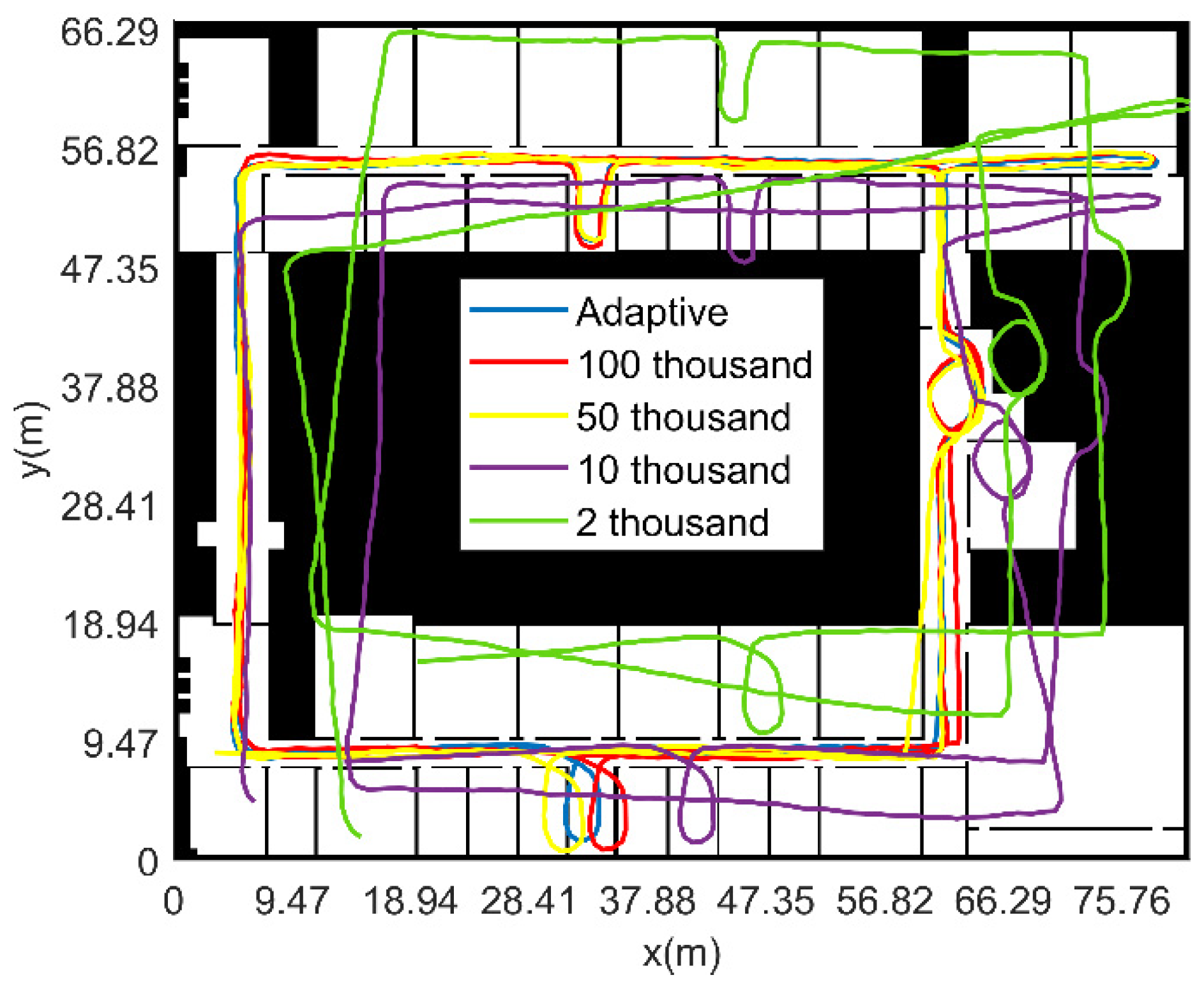
- The initial position and heading of pedestrian are unknown (fixed particle number)
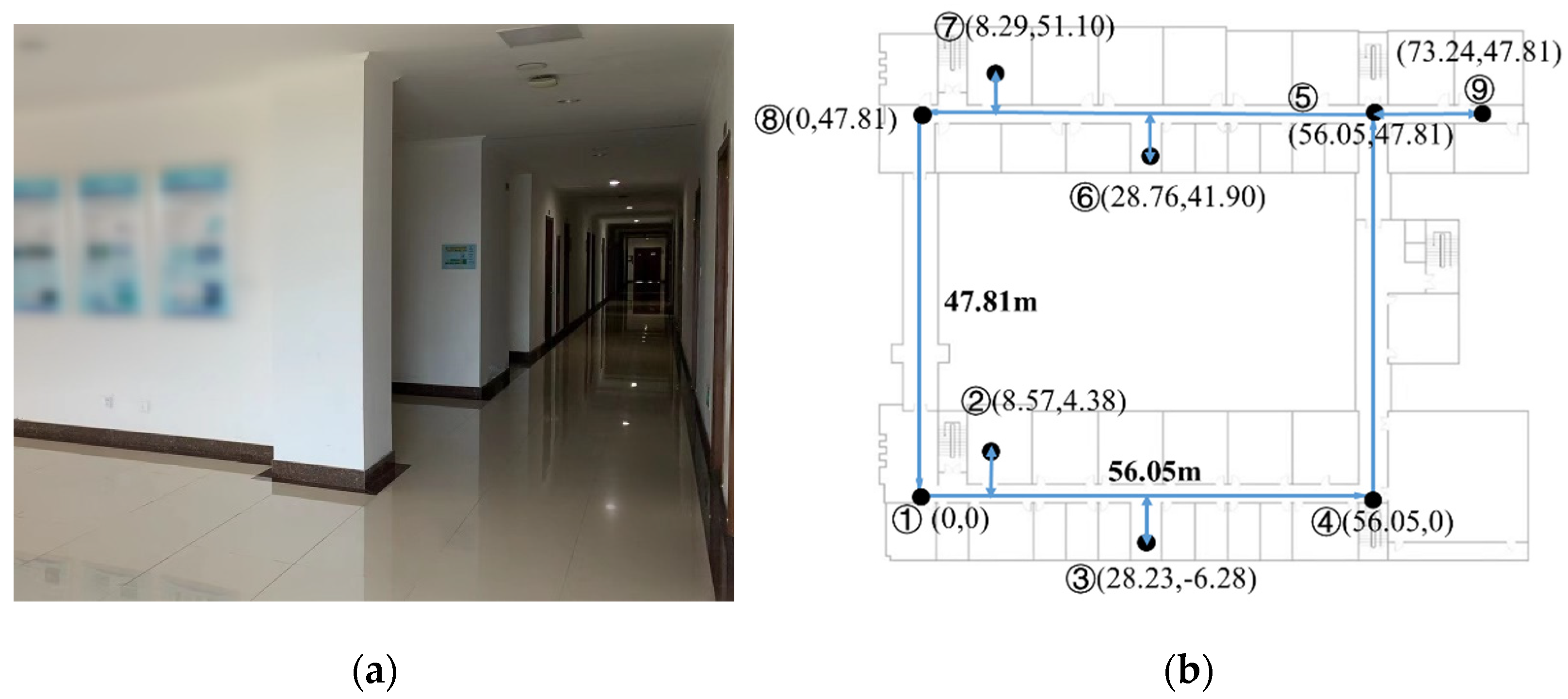
3.2. Experiment and Verification
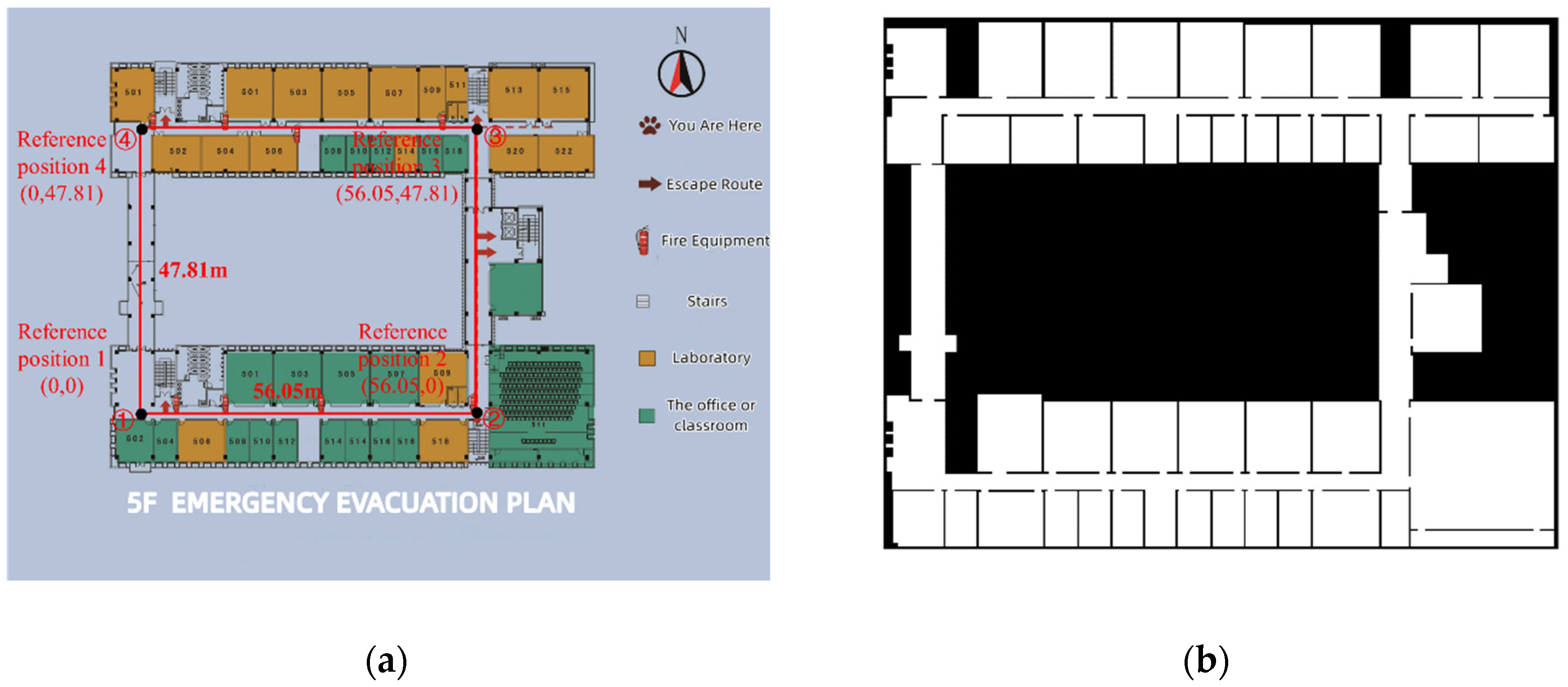
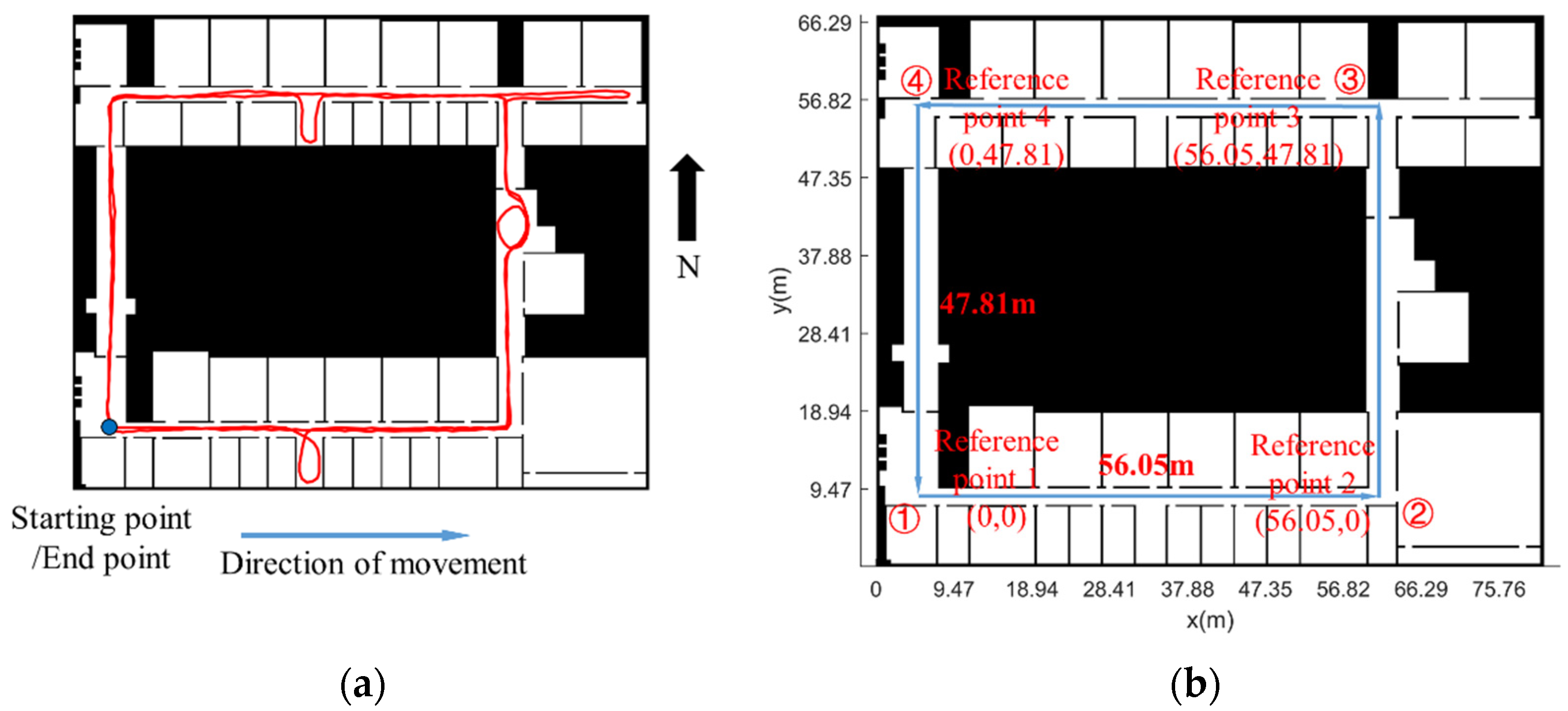
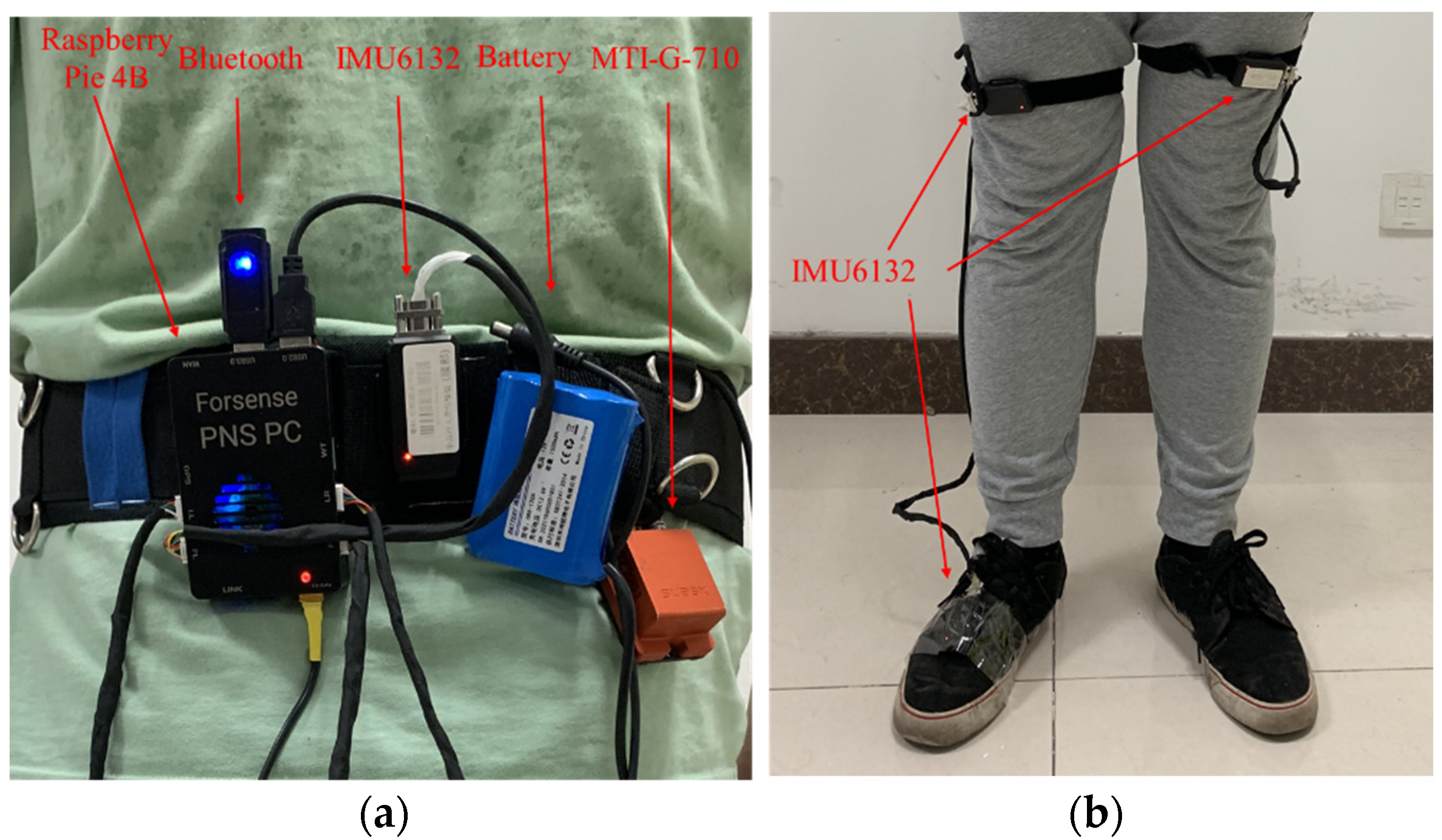
3.2.1. Experimental Conditions
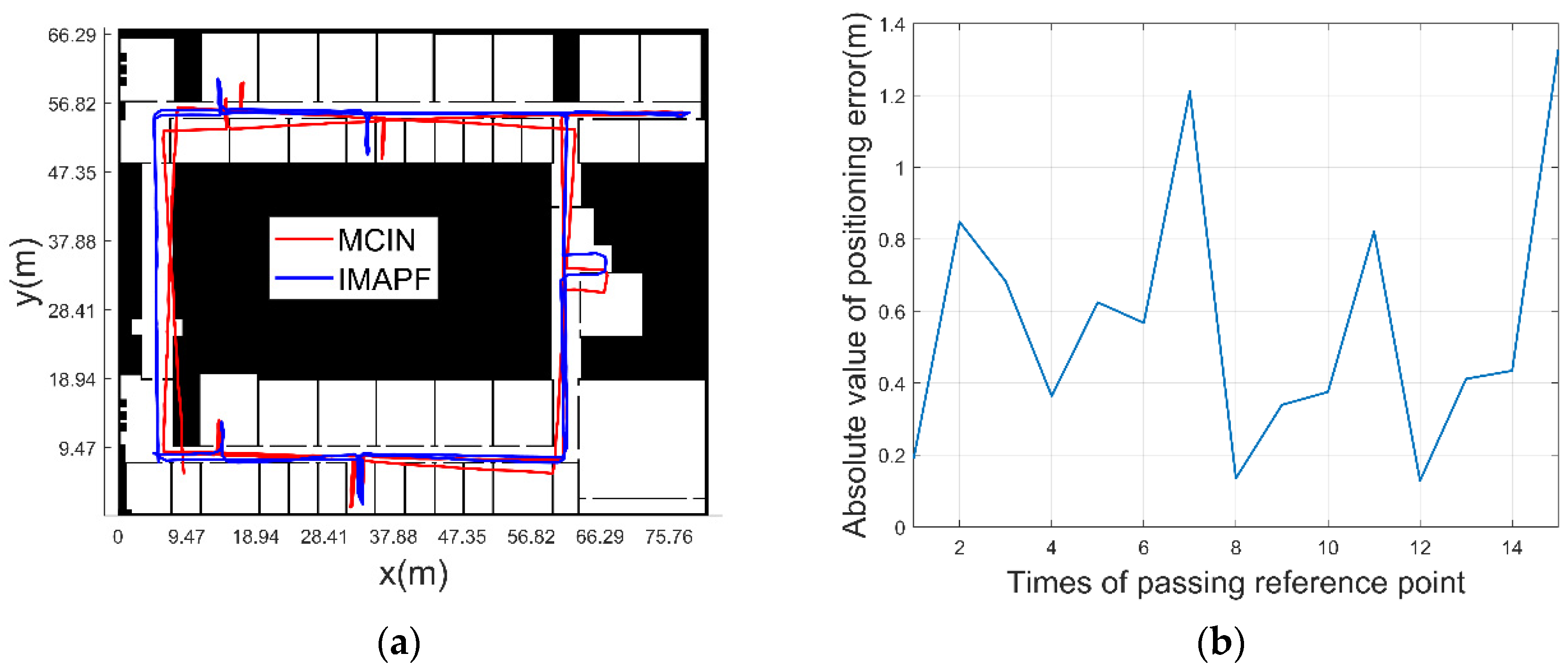
3.2.2. Experimental Verification Analysis
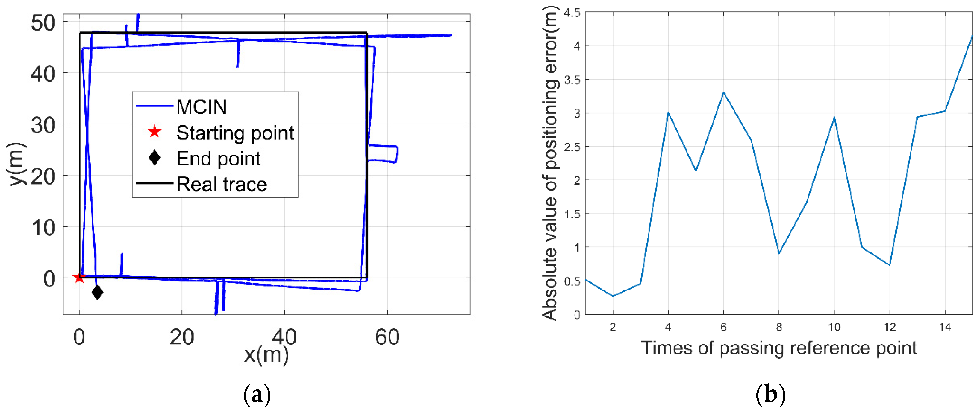
- (1)
- MCIN method
- (2)
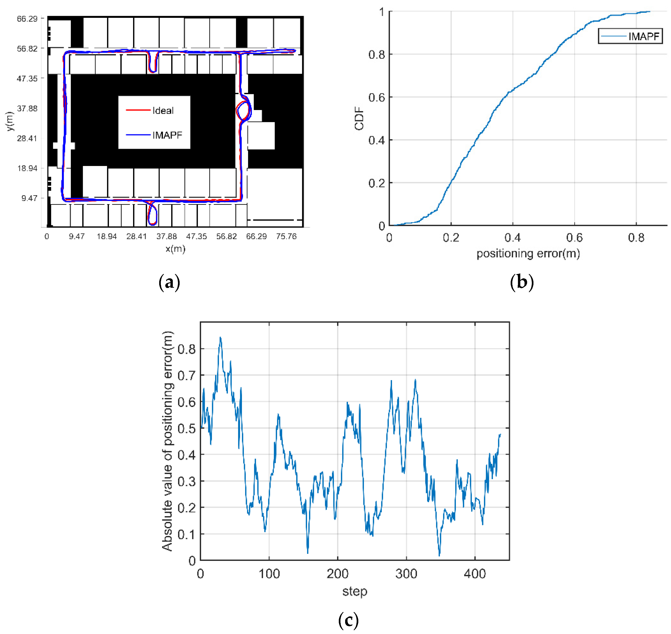
- The initial position and heading of pedestrian are known
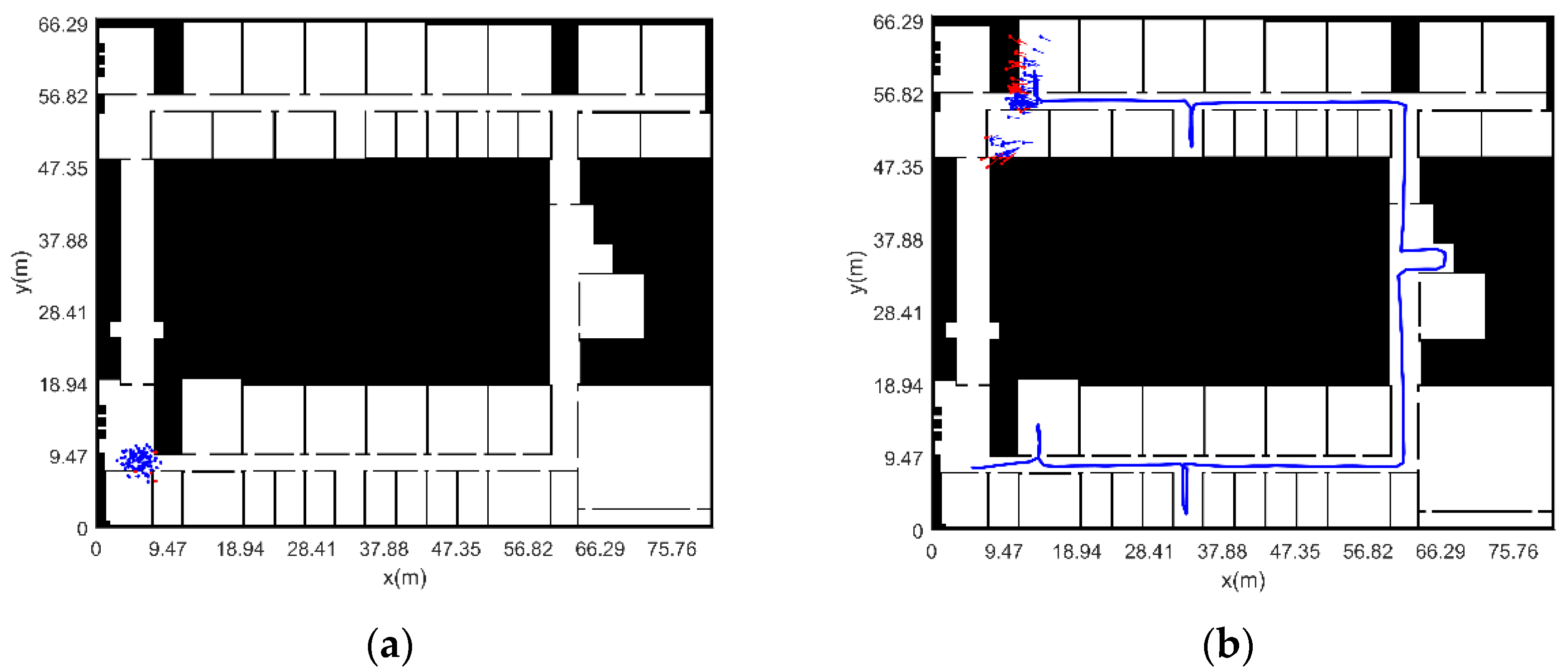
- (3)
- The initial position and heading of pedestrian are unknown (adaptive particle number)
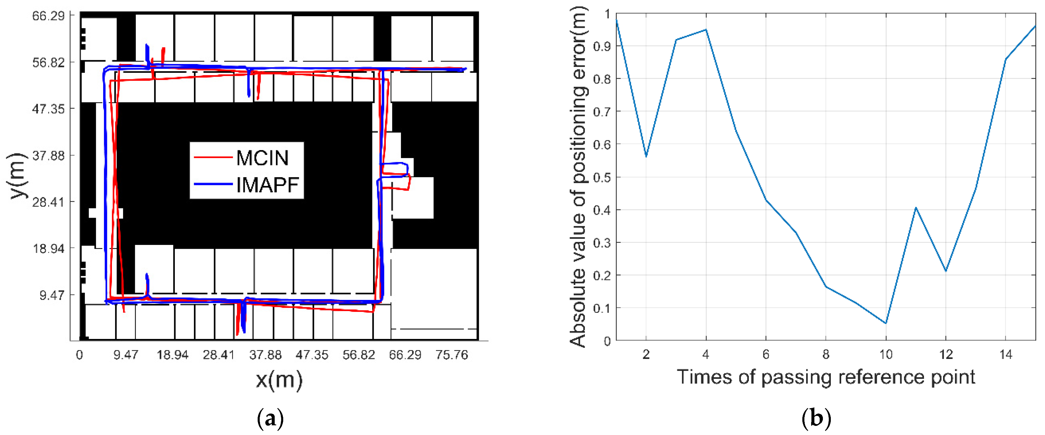
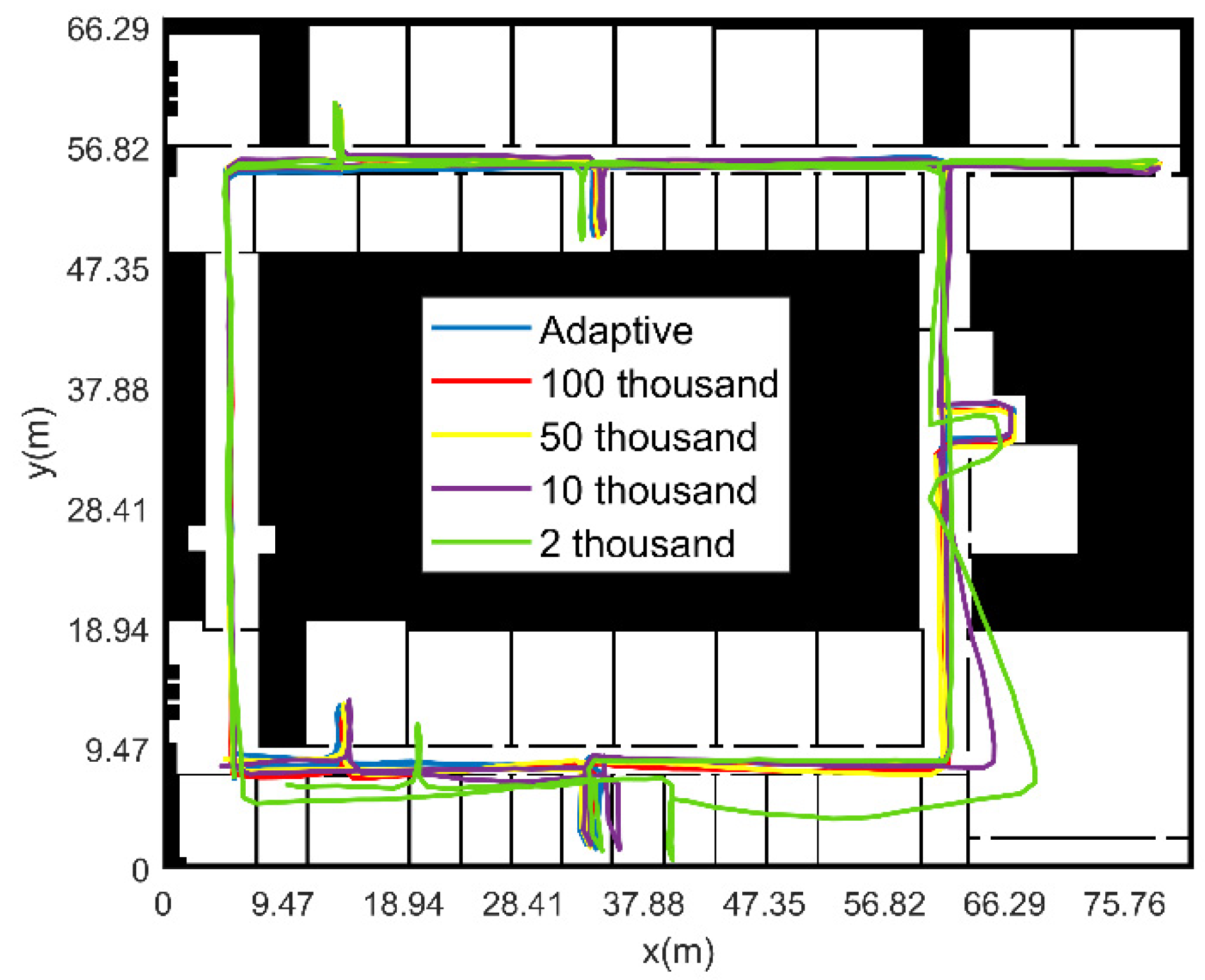
- (4)
- The initial position and heading of pedestrian are unknown (fixed particle number)
4. Discussion
5. Conclusions
Author Contributions
Funding
Data Availability Statement
Conflicts of Interest
References
- Jwo, D.J.; Lee, J.T. Kernel Entropy Based Extended Kalman Filter for GPS Navigation Processing. Comput. Mater. Contin. 2021, 68, 857–876. [Google Scholar]
- Cao, X.; Shen, F.; Zhang, S.; Li, J. Time delay bias between the second and third generation of BeiDou Navigation Satellite System and its effect on precise point positioning. Measurement 2021, 168, 108346. [Google Scholar] [CrossRef]
- Kröll, H.; Steiner, C. Indoor ultra-wideband location fingerprinting. In Proceedings of the 2010 International Conference on Indoor Positioning and Indoor Navigation, Zurich, Switzerland, 15–17 September 2010. [Google Scholar]
- Li, Y.; Zhuang, Y.; Zhang, P.; Lan, H.; Niu, X.; Naser, E.-S. An improved inertial/wifi/magnetic fusion structure for indoor navigation. Inf. Fusion 2017, 34, 101–119. [Google Scholar]
- Kriz, P.; Maly, F.; Kozel, T. Improving Indoor Localization Using Bluetooth Low Energy Beacons. Mob. Inf. Syst. 2016, 2016 Pt 2, 1–11. [Google Scholar] [CrossRef]
- Bianchi, V.; Ciampolini, P.; De Munari, I. RSSI-Based Indoor Localization and Identification for ZigBee Wireless Sensor Networks in Smart Homes. IEEE Trans. Instrum. Meas. 2019, 68, 566–575. [Google Scholar] [CrossRef]
- Chawla, K.; Thomason, W.; Mcfarland, C.; Robins, G. An accurate real-time RFID-based location system. Int. J. Radio Freq. Identif. Technol. Appl. 2018, 5, 48–76. [Google Scholar] [CrossRef]
- Nadarajah, V.R.; Singh, M.M. Privacy-by-Design(PbD) IoT Framework: A Case of Location Privacy Mitigation Strategies for Near Field Communication (NFC) Tag Sensor. Adv. Sci. Technol. Eng. Syst. J. 2017, 2, 134–138. [Google Scholar] [CrossRef][Green Version]
- Tian, D.; Ming, D.; Mao, G.; Lin, Z.; David, L.P. Uplink Performance Analysis of Dense Cellular Networks with LoS and NLoS Transmissions. IEEE Trans. Wirel. Commun. 2017, 16, 2601–2613. [Google Scholar]
- Mao, K.J.; Wu, J.B.; Jin, H.B.; Miao, C.Y.; Chen, Q.Z. Indoor localization algorithm for NLOS environment. Acta Electron. Sin. 2016, 44, 1174–1179. [Google Scholar]
- Marek, P.; Philippe, G.; Rasmus, A. Mapping forests using an unmanned ground vehicle with 3D LiDAR and graph-SLAM. Comput. Electron. Agric. 2018, 145, 217–225. [Google Scholar]
- Liu, J.; Gao, W.; Hu, Z. Bidirectional Trajectory Computation for Odometer-Aided Visual-Inertial SLAM. IEEE Robot. Autom. Lett. 2021, 99, 1670–1677. [Google Scholar] [CrossRef]
- Qureshi, U.; Golnaraghi, F. An algorithm for the in-field calibration of a MEMS IMU. IEEE Sens. J. 2017, 17, 7479–7486. [Google Scholar]
- Ahmed, D.B.; Diaz, E.M. Loose Coupling of Wearable-Based INSs with Automatic Heading Evaluation. Sensors 2017, 17, 2534. [Google Scholar] [CrossRef] [PubMed]
- Xu, L.; Xiong, Z.; Liu, J.; Wang, Z.; Ding, Y. A Novel Pedestrian Dead Reckoning Algorithm for Multi-Mode Recognition Based on Smartphones. Remote Sens. 2019, 11, 294. [Google Scholar] [CrossRef]
- Ding, Y.; Xiong, Z.; Li, W.; Cao, Z.; Wang, Z. Pedestrian Navigation System with Trinal-IMUs for Drastic Motions. Sensors 2020, 20, 5570. [Google Scholar]
- Ruppelt, J.; Kronenwett, N.; Scholz, G.; Trommer, G.F. High-precision and robust indoor localization based on foot-mounted inertial sensors. In Proceedings of the 2016 IEEE/ION Position, Location and Navigation Symposium (PLANS), Savannah, GA, USA, 11–14 April 2016; pp. 67–75. [Google Scholar]
- Hsu, Y.L.; Wang, J.S.; Chang, C.W. A Wearable Inertial Pedestrian Navigation System with Quaternion-Based Extended Kalman Filter for Pedestrian Localization. IEEE Sens. J. 2017, 17, 3193–3206. [Google Scholar] [CrossRef]
- Suresh, R.P.; Sridhar, V.; Pramod, J.; Talasila, V. Zero velocity potential update (ZUPT) as a correction technique. In Proceedings of the 2018 3rd International Conference on Internet of Things: Smart Innovation and Usages (IoT-SIU), Bhimtal, India, 23–24 February 2018; pp. 1–8. [Google Scholar]
- Abdallah, A.A.; Jao, C.S.; Kassas, Z.M.; Shkel, A.M. A pedestrian indoor navigation system using deep-learning-aided cellular signals and ZUPT-aided foot-mounted IMUs. IEEE Sens. J. 2021, 22, 5188–5198. [Google Scholar] [CrossRef]
- Ilyas, M.; Cho, K.; Baeg, S.-H.; Park, S. Drift reduction in pedestrian navigation system by exploiting motion constraints and magnetic field. Sensors 2016, 16, 1455. [Google Scholar] [CrossRef]
- Song, J.W.; Park, C.G. Enhanced pedestrian navigation based on course angle error estimation using cascaded Kalman filters. Sensors 2018, 18, 1281. [Google Scholar] [CrossRef]
- Diez, L.E.; Bahillo, A.; Bataineh, S.; Masegosa, A.D.; Perallos, A. Enhancing improved heuristic drift elimination for wrist-worn PDR systems in buildings. In Proceedings of the 2016 IEEE 84th Vehicular Technology Conference (VTC-Fall), Montreal, QC, Canada, 18–21 September 2016; pp. 1–5. [Google Scholar]
- Muhammad, M.N.; Salcic, Z.; Wang, K.I.-K. Detecting turns and correcting headings using low-cost INS. J. Navig. 2018, 71, 189–207. [Google Scholar] [CrossRef]
- Kim, S.-Y.; Park, Y.-Y.; Lee, K.-O.; Jung, J.-B.; Kye, J.-E. A Study on the Making Indoor Topology Map for the Autonomous Driving of Wearable Robots. Ilkogr. Online 2021, 20, 1153–1159. [Google Scholar]
- Angermann, M.; Robertson, P. FootSLAM: Pedestrian Simultaneous Localization and Mapping Without Exteroceptive Sensors—Hitchhiking on human perception and cognition. Proc. IEEE 2012, 100, 1840–1848. [Google Scholar] [CrossRef]
- Kaiser, S.; Puyol, M.G.; Robertson, P. Measuring the Uncertainty of Probabilistic Maps Representing Human Motion for Indoor Navigation. Mob. Inf. Syst. 2016, 2016, 9595306. [Google Scholar] [CrossRef]
- Wang, Q.; Luo, H.; Men, A.; Zhao, F.; Huang, Y. An Infrastructure-Free Indoor Localization Algorithm for Smartphones. Sensors 2018, 18, 3317. [Google Scholar] [CrossRef]
- Yu, C.; El-Sheimy, N.; Lan, H.; Liu, Z. Map-based indoor pedestrian navigation using an auxiliary particle filter. Micromachines 2017, 8, 225. [Google Scholar] [CrossRef]
- Wang, Z.; Xiong, Z.; Xing, L.; Ding, Y.; Sun, Y. A method for autonomous multi-motion modes recognition and navigation optimization for indoor pedestrian. Sensors 2022, 22, 5022. [Google Scholar] [CrossRef]


| Characteristic | Parameter |
|---|---|
| Computer operating system | Windows10 |
| CPU | Intel(R) Core(TM) i7-8700, Dominant frequency 3.20 GHz |
| Memory | 32 GB |
| Software | Matlab2020 |
| Navigation Method | Mean Error (m) | Maximum Error (m) |
|---|---|---|
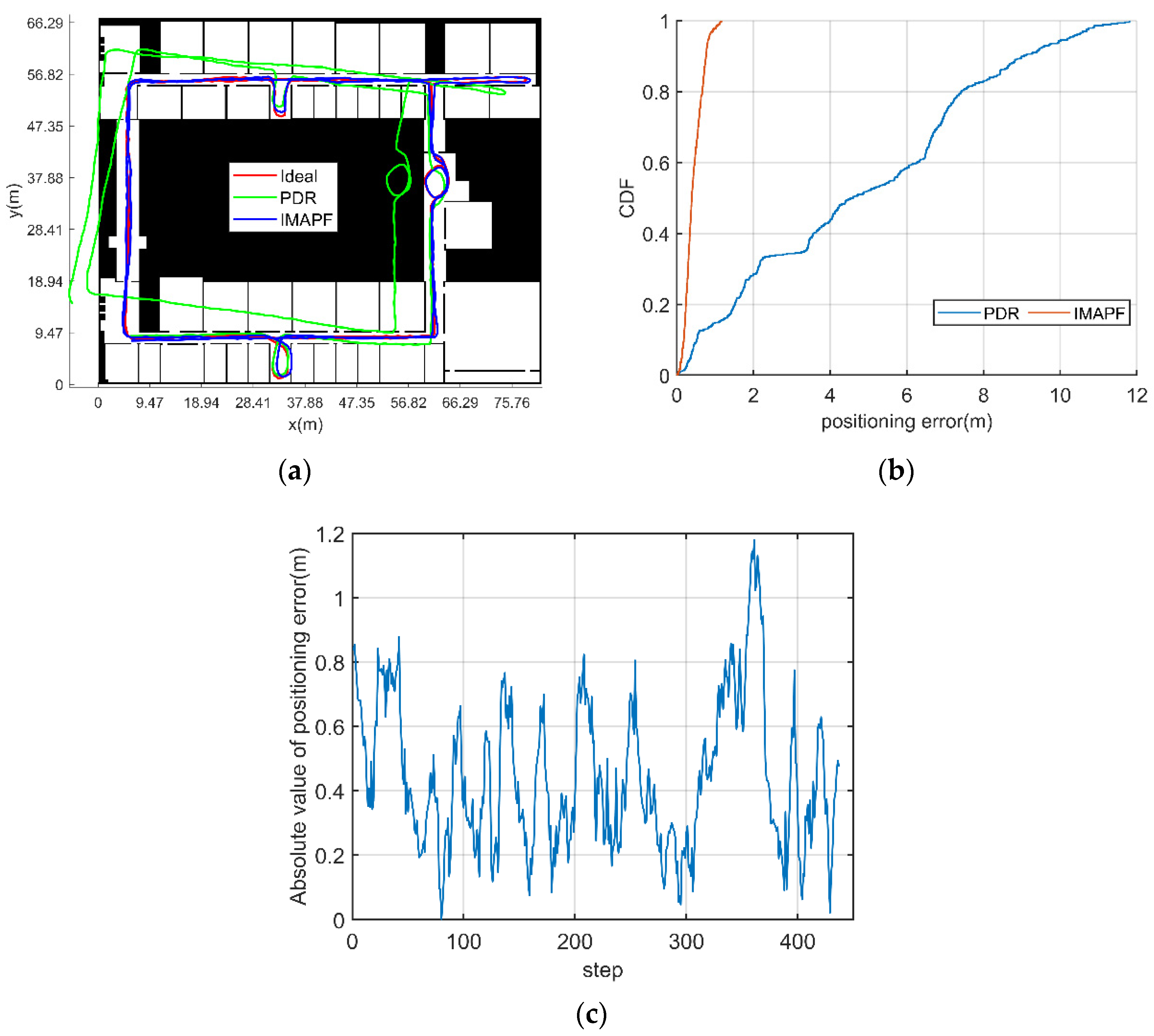
| PDR | 4.78 | 11.81 |
| IMAPF | 0.44 | 1.18 |
| Particle Number | Mean Error (m) | Maximum Error (m) | Calculation Time (s) |
|---|---|---|---|
| 2 thousand fixed particles | 10.34 | 15.99 | 16.64 |
| 10 thousand fixed particles | 7.74 | 12.07 | 103.05 |
| 50 thousand fixed particles | 0.75 | 3.01 | 909.04 |
| 100 thousand fixed particles | 0.50 | 1.91 | 2624.36 |
| adaptive particle numbers | 0.36 | 0.84 | 116.14 |
| / | Sensor Range | Bias Stability |
|---|---|---|
| Accelerometer | ||
| Gyroscope |
| / | Sensor Range | Total Root Mean Square Noise |
|---|---|---|
| Barometer |
| Navigation Method | Mean Error (m) | Maximum Error (m) |
|---|---|---|
| MCIN | 1.98 | 4.16 |
| IMAPF | 0.54 | 0.98 |
| Particle number | Mean Error (m) | Maximum Error (m) | Calculation Time (s) |
|---|---|---|---|
| 2 thousand fixed particles | 3.89 | 7.03 | 16.37 |
| 10 thousand fixed particles | 2.74 | 9.21 | 93.02 |
| 50 thousand fixed particles | 1.13 | 1.40 | 755.33 |
| 100 thousand fixed particles | 1.04 | 1.11 | 2229.13 |
| adaptive particle number | 1.06 | 1.33 | 131.59 |
Publisher’s Note: MDPI stays neutral with regard to jurisdictional claims in published maps and institutional affiliations. |
© 2022 by the authors. Licensee MDPI, Basel, Switzerland. This article is an open access article distributed under the terms and conditions of the Creative Commons Attribution (CC BY) license (https://creativecommons.org/licenses/by/4.0/).
Share and Cite
Wang, Z.; Xing, L.; Xiong, Z.; Ding, Y.; Sun, Y.; Shi, C. An Improved Pedestrian Navigation Method Based on the Combination of Indoor Map Assistance and Adaptive Particle Filter. Remote Sens. 2022, 14, 6282. https://doi.org/10.3390/rs14246282
Wang Z, Xing L, Xiong Z, Ding Y, Sun Y, Shi C. An Improved Pedestrian Navigation Method Based on the Combination of Indoor Map Assistance and Adaptive Particle Filter. Remote Sensing. 2022; 14(24):6282. https://doi.org/10.3390/rs14246282
Chicago/Turabian StyleWang, Zhengchun, Li Xing, Zhi Xiong, Yiming Ding, Yinshou Sun, and Chenfa Shi. 2022. "An Improved Pedestrian Navigation Method Based on the Combination of Indoor Map Assistance and Adaptive Particle Filter" Remote Sensing 14, no. 24: 6282. https://doi.org/10.3390/rs14246282
APA StyleWang, Z., Xing, L., Xiong, Z., Ding, Y., Sun, Y., & Shi, C. (2022). An Improved Pedestrian Navigation Method Based on the Combination of Indoor Map Assistance and Adaptive Particle Filter. Remote Sensing, 14(24), 6282. https://doi.org/10.3390/rs14246282