Abstract
In many cases, we have few optical observations over a short time span, and most of the information generated is too limited to compute a full orbit according to the angles-only method. This study aims to develop a mathematical model to determine the precise orbit from the optical observation data by the least squares method. We have used a set of the Global Navigational Satellite Systems, which are tracked by the Optical Satellite Tracking Station (OSTS) at the National Research Institute of Astronomy and Geophysics (NRIAG), Egypt, to access high-quality predictions for the orbits. We analyzed the orbit predictions from the observations of these satellites that are tracked from seven world stations using the laser ranging method, and the obtained results are compared with orbital elements produced using the Two-Line Element (TLE). The results showed that the orbital prediction accuracy differs for optical observations from laser observations because of the inaccuracy of the NORAD catalog information used; this is due to the difference between the time of observation and the epoch time of TLE.
1. Introduction
Satellite Laser Ranging (SLR) is a technique for measuring the range of satellites, which represents the distance between the satellite and the tracking station. The SLR is considered to be one of the most accurate methods for tracking artificial earth satellites [,]. Galileo, the European Global Navigation Satellite System (GNSS), has 26 satellites in orbit. The International Laser Ranging Service introduces some SLR observations for Galileo satellites. They are equipped with a satellite laser ranging retroreflector consisting of 84 and 60 corner cube retroreflectors that allow the assessment of the orbit accuracy in space [].
The laser tracking sensors transmit laser pulses and calculate the range by collecting the returned signals, where the angle data are generated by collecting the sunlight-illuminated satellites with about 2–5 arc second accuracy. The range measurement is collected by measuring the two-way time of flight with laser retroreflectors. The SLR is used in many applications, including space geodesy and geodynamics [].
When the orbit is predicted using the North American Aerospace Defense Command (NORAD), the resultant pointing errors are usually in the order of tens to hundreds of arc seconds []. While we must have sufficiently accurate orbit predictions to achieve high efficiency of satellite laser tracking (better than 20 arc seconds) because of the narrow laser beam. Cordelli et al. [] investigated the improvements to orbit predictions (OP) accuracy by combining the angle data from both the SLR and the Optical Ground Sites. Li et al. [] have shown that using the Two-Line Elements to calculate positions every 10 min is sufficient to help achieve orbit determination (OD) convergence in the case where only the angular data over a short orbit arc are available. Lejba and Schillak [] determined the positions and velocities of four SLR stations (Australian Yarragadee, North American Greenbelt, and two European, Graz and Herstmonceux) from the orbits of LEO satellites. Where the orbital computations were performed on the basis of the observations of 20 SLR stations and then compared the final results with the LAGEOS data. Schillak et al. [] used the results of the laser observations from the LARES satellite to determine the station coordinates, and they compared the results with the LAGEOS-1 and LAGEOS-2 satellites. The earth tides are generated by the gravitational effect of the Moon and the Sun, which cause variations in the mass distribution of the Earth. The estimated parameters Love and Shida numbers for second-degree tides are based on the analysis of the SLR data, where the values of these parameters are equal to 0.6140 ± 0.0005 for Shida and 0.0876 ± 0.0002 for Love (Jagoda and Rutkowska [], Rutkowska and Jagoda []). Sośnica et al. [] and Sośnica [] studied ocean tide models based on the analysis of LAGEOS satellite altimetry data the results show that differences between LAGEOS orbits derived using modern gravity field models are rather small, while the more important role in the quality of resulting LAGEOS orbits result from ocean tides, station loading displacement corrections, and technical station errors. In this study, we combine angle and laser ranging data to investigate improvements in the accuracy of the orbit prediction using the OSTS station and some other laser ranging stations from the International Laser Ranging Service. Several results of Galileo orbits were demonstrated under a limited observation environment to verify the OP accuracy through the combination of angle and laser ranging data from serval sites.
2. Sites Description
The optical characterization of satellites in different orbits is challenging because satellites in some orbits have low signal levels that typically require long exposure times although background stars will appear as streaks in the images, some satellites remain fixed in the field of view during the observation time, such as in GEO, and others appear as a movement trail, such as GNSS satellites, as shown in Figure 1. The observations are taken by selecting a field of view with a specific right ascension and declination, corresponding to a fixed solar phase angle (observatory–target–Sun), which remains outside of the Earth’s shadow. For image processing, we used APEX II software to make astrometry photometry, and identify the satellite in this image [].
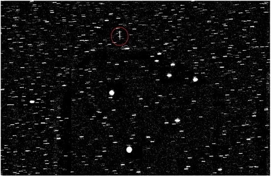
Figure 1.
Examples of GEO and GNSS (inside red circle) satellites during observation from the OSTS station.
In this section, we will explain the design of the fundamentals of the electro-optical system [] and SLR stations.
2.1. Optical Satellite Tracking Station
Electro-optical (EO) is used in this study from the Optical Satellite Tracking Station (OSTS) at Kottamia observatory, National Research Institute of Astronomy and Geophysics (NRIAG), Egypt, as shown in Figure 2, and more details are given in Table 1 [,]. The OSTS is a part of the International Scientific Optical Network (ISON) [].
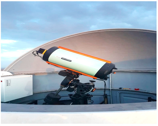
Figure 2.
The OSTS station—NRIAG, Egypt.

Table 1.
The fundamentals of the optical Satellite Tracking Station (OSTS).
2.2. The Satellite Laser Ranging Stations
The Satellite Laser Ranging technique aims to measure the distance between the SLR station and the center of mass of the satellite equipped with a retroreflector. This is achieved by measuring the two-way time of flight of light pulses between the satellite and station. This requires correcting for the distance measured to the satellite for the effects of the decrease in the speed of light and the difference between the curved and straight ray paths (Jagoda et al. []). There are several factors that must be taken into consideration, such as the distance from the retroreflector to the mass center of the satellite, impact of satellite motion, Earth rotation, and relativistic effects (Jagoda et al. [], Schillak [], Schillak et al. []).
The laser observation equation for the i-th laser measurement of a distance to the satellite mass center can be written as (Jagoda et al. [])
where is the two-way time interval of flight of light pulses between the station and satellite for the i-th measurement, Δc is calibration correction, C is the speed of light, and are tropospheric delay for the i-th measurement (due to the twice passage of the light pulse through the atmosphere) and correction for the center of the satellite mass (25.1 cm for LAGEOS satellites), respectively, is the range bias of the observation, is the relativistic range correction, and are the impact of satellite motion and Earth rotation, respectively, is a random error for the i-th measurement, and is the distance calculated for the i-th measurement.
We have taken our data from different SLR stations, Mendeleevo, Moscow, Russia (1874), Zelenchukskaya Karachaevo, Cherkesi, Russia (1889), Changchun, Jilin, China (7237), Fangshan district Beijing, China (7249), Canberra Australian Capital Territory, Australia (7825), Potsdam Brandenburg, Germany (7841), and Matera Basilicata Italy (7941). The specifications contain the longitude, latitude, and height above mean sea level and these important parameters are given in Table 2.

Table 2.
Laser satellite tracking stations (LSR).
3. Precise Orbit Determination
The Initial Orbit Determination (IOD) problem can be solved for the angles only by the Laplace, the Gauss, the Double-r, and the Gooding methods. These methods depend on choosing only three pairs of observations, with many observations wasted. For the angles-only method, we used either the topocentric right ascension, declination, and time of objects in the case of the optical system or azimuth and elevation in the case of SLR stations. From the angular measurements, we can form the vector of direction cosine with respect to a space-fixed reference frame. If we know the slant range and observation site’s location, we could easily get an expression for the satellite’s position vector [,,].
To reduce the influence of measurement error and improve the accuracy of the initial orbit determination, the improved Laplace method utilizes all observations. However, the improved Laplace method cannot give the optimal IOD solution. In this work, we used the least squares method to solve IOD problems and refine them by minimizing the measurement errors directly. The Laplace-LS IOD is the direct method to minimize the errors between the virtual and true observations [].
Assuming we have n groups of noisy measurements of right ascensions () and declination ()
The actual observation sequence with measurement noise is defined as
The theoretical observation sequence of the true orbit (without noise) is defined as
Supposing the measurement errors follow a normal distribution with variance σ2, the observed ascensions and declinations have the following statistical characteristics
At any initial epoch t0 and state x0, there is a theoretical observation sequence calculated by the dynamical model and the observation model.
Now, we get the difference between the given orbit x0 and the actual orbit from the weighted square sum of the errors between the theoretical observations and the actual observations.
The average angle error can be determined by the root mean square error (RMSE) of the errors (defined as the target function J(x0)), which indicates the average angle error.
After some process, we can estimate the Cartesian components (position and velocity) of the orbit state []. From state vectors, we can directly solve for the classical orbital elements, as follows in Appendix A.
4. Results and Discussions
Now, we will determine the precise orbit using five space object targets in MEO that were selected (NORAD catalog ID 37139, 32393, 40315, 38857, and 37867). Table 3 shows the total number of observations from optical and SLR stations.

Table 3.
The observations from optical and SLR stations.
4.1. Orbital Element of Space Object Descriptions
The primary goal of Satellite Laser Ranging is the measurement of the time required for pulses emitted by a laser transmitter to travel to a satellite and return to the transmitting site, which is the range, as shown in Figure 3 for the satellite Galileo 103, as an example, which was observed on 12 July 2021.
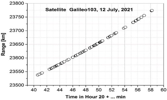
Figure 3.
The range of the satellite Galileo 103 observed on 12 July 2021.
The tracking object observed from different sites during the period from 8 to 11 July 2021 are given in Table 3. The description of the orbital element used for the real observation to demonstrate the OP accuracy and the proposed initial estimation is given in Table 4.

Table 4.
The description of space object targets in MEO.
4.2. The Numerical Simulations for Optical and SLR Observation
In this subsection, we used the least-squares differential correction algorithm to determine the orbit of the satellites from the simulation of position and velocity measurements generated along the reference orbit. We developed a mathematical model using the MATLAB© package; it is applied to Optical and SLR observation parameters. The precise orbit determination is shown in Table 5. The table shows the orbital elements for the semi-major axis (a), inclination angle (i), and eccentricity (e) for the optical observation and the data available from NORAD and shows the difference between them; , , and . The accuracy of the semi-major axis is about 600 to 2000 m, the inclination is about 10−3, and the angle of eccentricity is about 10−4.

Table 5.
Optical observation parameters.
On the other hand, the data given in Table 6 give the accuracy, as calculated from SLR observations in the semi-major axis ranging from 40 to 400 m. We have the observation of the object COSMOS 2464 on 9 July 2021 from optical and laser stations. The object COSMOS 2501 is tracking from two laser stations on the 8 and 9 of July 2021. The accuracy of the observation from the laser stations is nearly similar to the same results of different observation times. As we show, there is a clear difference in the results when comparing the two monitoring systems. This difference is because, in the case of the ground-based optical system, the space object appears as a trail and not as a point, so we take the start point and the end point for every shot; this leads to an error in angular measurements, and we are trying to fix that by fitting a line or polynomial to the trail to obtain more data input. This is because the OSTS has an equatorial mount, and the right ascension axis is fixed. While all SLR sensors are alt-azimuth mounts that have the rate of change on their axis.

Table 6.
SLR observation parameters.
The Figure 4, Figure 5, Figure 6, Figure 7 and Figure 8 show the relationship between the position residuals and the time. The effects of perturbation on artificial satellites (Earth’s gravity, solar radiation pressure, and the third body) have been considered []. The model errors on relative position residuals of different examples are shown, where the green curve explains the variation in the x-axis after 3 days, the red curve shows the variation in the z-axis, and the yellow curve shows the variation in the y-axis. The results for different examples show the drift error for X residual position, Y residual, and Z residual are increases in the range of 10−4 km.
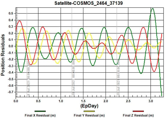
Figure 4.
The relationship between the position residuals and the time for satellite“COSMOS-2464”.
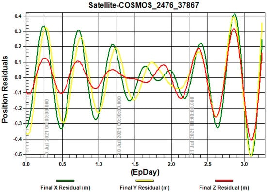
Figure 5.
The relationship between the position residuals and the time for satellite “COSMOS-2476”.
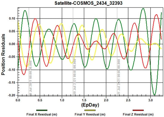
Figure 6.
The relationship between the position residuals and the time for satellite “COSMOS-2434”.
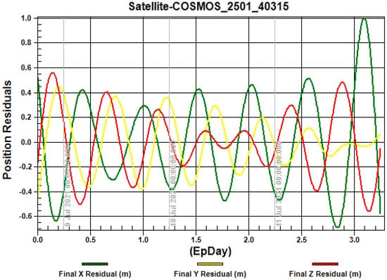
Figure 7.
The relationship between the position residuals and the time for satellite “COSMOS-2501”.
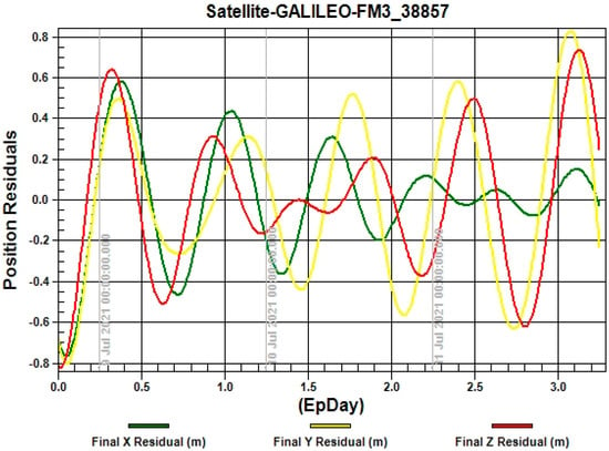
Figure 8.
The relationship between the position residuals and the time for satellite “GALILEO-38857”.
5. Conclusions
In this paper, we developed a mathematical model to determine the precise orbit from optical and laser observation data. We applied our model to different Global Navigational Satellite Systems. The optical observation method is used by the Optical Satellite Tracking Station (OSTS) at NRIAG—Egypt, and the SLR observation methods are produced from some stations of the International Laser Ranging Service for the Galileo satellites. We used the least squares method to refine the orbit derived from the IOD method; these methods depend on choosing only three pairs of observations. The cases using the angle and laser ranging data together (Cases 37139, 40315) satisfied the target OP accuracy (about 400 m at 19,000 km altitude). This is consequent to the error of OP accuracy coming from the inaccuracy of NORAD catalog information because of the difference between the time of observation and the epoch time of TLE. Compared with the TLE, our results showed that the accuracy of the calculations is better using SLR observations.
Author Contributions
A.M.A., S.K.T. and M.I.: common plan; A.M.A. and S.K.T.: the draft of the manuscript, and processed the original satellite data from OSTS; M.I., Z.L. and X.D.: provided the data from the SLR stations. All authors have read and agreed to the published version of the manuscript.
Funding
The APC was funded by the National Research Institute of Astronomy and Geophysics (NRIAG), Helwan, Cairo, Egypt.
Acknowledgments
The authors, therefore, acknowledge with thanks NRIAG technical and financial support. We acknowledge the ILRS for providing SLR tracking data and orbit products for GNSS.
Conflicts of Interest
The authors declare that they have no known competing financial interests or personal relationships that could have appeared to influence the work reported in this paper.
Appendix A. Cartesian Coordinates to Classical Orbital Elements (Elliptical Case)
We can compute orbital elements given the ECI position and velocity at time t for elliptical motion from the following equations. To compute the specific angular momentum and check for a degenerate orbit,
We compute the radius, r, and velocity, v,
We compute the specific energy, ε, and verify elliptical motion,
We compute the semi-major axis, a,
We compute the eccentricity, e,
We compute the inclination, i, (0° → 180°),
We compute the right ascension of the ascending node, Ω, (0° → 360°),
We compute the argument of latitude, , (0° → 360°),
We compute the true anomaly, ν, (0° → 360°),
If > 0 then . Or use
We compute the argument of periapse, ω (0° → 360°),
We compute the eccentric anomaly, E, (0° → 360°),
where E is in the same half-plane as ν.
This equation will yield the correct quadrant for ν.
We compute the time of periapse passage, T (note that E must be in radians),
References
- Ibrahim, M.; Hanna, Y.; Samwel, S.; Hegazy, M. Satellite Laser Ranging in Egypt. NRIAG J. Astron. Geophys. 2015, 4, 123–129. [Google Scholar] [CrossRef]
- Ibrahim, M. 17 years of ranging from the Helwan SLR station. Astrophys. Space Sci. 2011, 335, 379–387. [Google Scholar] [CrossRef]
- Sośnica, K.; Prange, L.; Kazmierski, K.; Bury, G.; Drożdżewski, M.; Zajdel, R.; Hadas, T. Validation of Galileo orbits using SLR with a focus on satellites launched into incorrect orbital planes. J. Geod. 2017, 92, 131–148. [Google Scholar] [CrossRef]
- Kim, S.; Lim, H.-C.; Bennett, J.C.; Lachut, M.; Jo, J.H.; Choi, J.; Choi, M.; Park, E.; Yu, S.-Y.; Sung, K.-P. Analysis of Space Debris Orbit Prediction Using Angle and Laser Ranging Data from Two Tracking Sites under Limited Observation Environment. Sensors 2020, 20, 1950. [Google Scholar] [CrossRef] [PubMed]
- Vallado, D.; Agapov, V. Orbit Determination Results for Optical Measurements. In Proceedings of the AIAA/AAS Astrodynamics Specialist Conference, Toronto, ON, Canada, 2–5 August 2010. [Google Scholar] [CrossRef]
- Cordelli, E.; Vananti, A.; Schildknecht, T. Fusion of laser range and angle measurements data for LEO and GEO space debris orbit determination. In Proceedings of the 7th European Conference on Space Debris, Darmstadt, Germany, 18–21 April 2017; Available online: https://conference.sdo.esoc.esa.int/proceedings/sdc7/paper/445 (accessed on 31 July 2022).
- Li, B.; Sang, J.; Zhang, Z. A Real-Time Orbit Determination Method for Smooth Transition from Optical Tracking to Laser Ranging of Debris. Sensors 2016, 16, 962. [Google Scholar] [CrossRef] [PubMed]
- Lejba, P.; Schillak, S. Determination of station positions and velocities from laser ranging observations to Ajisai, Starlette and Stella satellites. Adv. Space Res. 2011, 47, 654–662. [Google Scholar] [CrossRef]
- Schillak, S.; Lejba, P.; Michalek, P. Analysis of the Quality of SLR Station Coordinates Determined from Laser Ranging to the LARES Satellite. Sensors 2021, 21, 737. [Google Scholar] [CrossRef] [PubMed]
- Jagoda, M.; Rutkowska, M. Estimation of the Love numbers: k2, k3 using SLR data of the LAGEOS1, LAGEOS2, STELLA and STARLETTE satellites. Acta Geod. Geophys. 2016, 51, 493–504. [Google Scholar] [CrossRef]
- Rutkowska, M.; Jagoda, M. Estimation of the Elastic Earth Parameters using the SLR LAGEOS 1 and LAGEOS 2 Data. Acta Geophys. 2010, 58, 705–716. [Google Scholar] [CrossRef]
- Sośnica, K.; Thaller, D.; Jäggi, A.; Dach, R.; Beutler, G. Sensitivity of Lageos Orbits to Global Gravity Field Models. Artif. Satell. 2012, 47, 47–65. [Google Scholar] [CrossRef]
- Sośnica, K. LAGEOS Sensitivity to Ocean Tides. Acta Geophys. 2015, 63, 1181–1203. [Google Scholar] [CrossRef]
- Abdel-Aziz, Y.; Abdelaziz, A.; Tealib, S.; Attia, G.; Molotov, I.; Schmalz, S. First Optical Satellite Tracking Station (OSTS) at NRIAG-Egypt. New Astron. 2020, 77, 101361. [Google Scholar] [CrossRef]
- Gasdia, F.; Barjatya, A.; Bilardi, S. Multi-Site Simultaneous Time-Resolved Photometry with a Low Cost Electro-Optics System. Sensors 2017, 17, 1239. [Google Scholar] [CrossRef] [PubMed]
- Abdelaziz, A.M.; Tealib, S.K.; Molotov, I. Analytical study of Egyptian TIBA-1 satellite orbit from Optical Satellite Tracking Station (OSTS), NRIAG-Egypt. Astrophys. Space Sci. 2021, 366, 81. [Google Scholar] [CrossRef]
- Molotov, I.E.; Krugly, Y.N.; Elenin, L.V.; Schildknecht, T.; Rumyantsev, V.V.; Inasaridze, R.Y.; Aivazyan, V.R.; Kapanadze, G.V.; Canals, L.R.; Graziani, F.; et al. Search and study of the space debris and asteroids within ISON project. An. Acad. Bras. Ciênc. 2021, 93 (Suppl. S1), e20200145. [Google Scholar] [CrossRef] [PubMed]
- Jagoda, M.; Rutkowska, M.; Kraszewska, K. The evaluation of time variability of tidal parameters h and l using SLR technique. Acta Geodyn. Geomater. 2016, 14, 153–158. [Google Scholar] [CrossRef]
- Schillak, S. Analysis of the process of the determination of station coordinates by the Satellite Laser Ranging based on results of the Borowiec SLR station in 1993.5–2000.5. Artif. Satell. 2004, 39, 265–287. [Google Scholar]
- Schillak, S.; Lejba, P.; Michałek, P.; Suchodolski, T.; Smagło, A.; Zapaśnik, S. Analysis of the Results of the Borowiec SLR Station (7811) for the Period 1993–2019 as an Example of the Quality Assessment of Satellite Laser Ranging Stations. Sensors 2022, 22, 616. [Google Scholar] [CrossRef] [PubMed]
- Schaeperkoetter, A.V. A Comprehensive Comparison between Angles-Only Initial Orbit Determination Techniques. Doctoral Dissertation, Texas A & M University, College Station, TX, USA, 2012. Available online: https://oaktrust.library.tamu.edu/handle/1969.1/ETD-TAMU-2011-12-10242 (accessed on 31 July 2022).
- Feng, F.; Zhang, Y.; Li, H.; Fang, Y.; Huang, Q.; Tao, X. A Novel Space-Based Orbit Determination Method Based on Distribution Regression and Its Sparse Solution. IEEE Access 2019, 7, 133203–133217. [Google Scholar] [CrossRef]
- Tao, X.; Li, Z.; Gong, Q.; Zhang, Y.; Jiang, P. Uncertainty Analysis of the Short-Arc Initial Orbit Determination. IEEE Access 2020, 8, 38045–38059. [Google Scholar] [CrossRef]
Publisher’s Note: MDPI stays neutral with regard to jurisdictional claims in published maps and institutional affiliations. |
© 2022 by the authors. Licensee MDPI, Basel, Switzerland. This article is an open access article distributed under the terms and conditions of the Creative Commons Attribution (CC BY) license (https://creativecommons.org/licenses/by/4.0/).