Communication

Transmit Antenna Selection and Power Allocation for Joint Multi-Target Localization and Discrimination in MIMO Radar with Distributed Antennas under Deception Jamming

1
Air and Missile Defense College, Air Force Engineering University, Xi’an 710051, China
2
Wuhan Electronic Information Institute, Wuhan 410039, China
3
Key Laboratory of Knowledge Engineering with Big Data, Ministry of Education, Hefei University of Technology, Hefei 230601, China
*
Author to whom correspondence should be addressed.
Remote Sens. 2022, 14(16), 3904; https://doi.org/10.3390/rs14163904
Submission received: 28 July 2022 / Revised: 6 August 2022 / Accepted: 9 August 2022 / Published: 11 August 2022
(This article belongs to the Special Issue Small or Moving Target Detection with Advanced Radar System)

Abstract

:
In this paper, with the aim of performing joint multi-target localization and discrimination tasks, a performance-driven resource allocation scheme is proposed. In the first, by establishing the signal model under deception jamming and utilizing the maximum likelihood (ML) estimator, the estimation information of targets can be obtained. Secondly, the Cramer–Rao lower bound (CRLB) for the transmit antenna selection and power allocation is derived. Then, to fully utilize the difference in spatial distribution between true and false targets, a false target discriminator based on the CRLB of the distance deception parameter is utilized. By introducing the nondimensionalization mechanism, we build an optimal objective function of target localization error and discrimination probability. Subsequently, a joint multi-target localization and discrimination optimization model has been established, which is mathematically a non-smooth and non-convex problem. By introducing an auxiliary variable, we propose a three-step solution strategy for solving this problem. Simulation results demonstrate that the proposed algorithm can improve the performance of joint localization accuracy and discrimination ability (JLADA) by more than 30% compared with the algorithms only for localization or discrimination. Meanwhile, by utilizing the proposed algorithm, the composite indicators of JLADA can decrease more than 70% compared with the uniform allocation scheme.

1. Introduction

By combining information from multiple nodes, the multiple radar system (MRS) can fully benefit from the advantages of multi-angle observation and increased area coverage, enabling stronger ability in detecting and locating targets for defense purposes [1]. As a typical representative of the MRS, based on the “defocused transmit and focused receive” (DTFR) mode [2], the distributed multiple-input multiple-output (MIMO) radar system has high spatial diversity gain, structure diversity gain [3], polarization diversity gain [4] and waveform diversity gain [5]. In theory, although the MIMO radar system has superior detection and parameter estimation capabilities, the physical resources and the hardware resources in the system are often finite, which becomes the main obstacle that limits the potential of MIMO radar. Generally speaking, when more antennas and higher transmit power budget are involved in the fixed radar system, the better performance of detection and parameter estimation can be obtained [6]. However, too many active antennas require a lot of data transmission and can cause a heavy computational burden to the fusion center. Furthermore, the most radar systems can only provide finite power resource due to hardware limitations. Therefore, in order to increase the potential of the distributed MIMO radar system, the antenna selection or power allocation problem has been studied in [3,5,6,7,8,9,10,11,12,13]. These studies seem to be fruitful for the resource allocation in MIMO radar, however, to the best of our knowledge, the resource allocation problem of simultaneously multiple tasks application under deception jamming has not been studied. Moreover, the powerful multi-direction observation ability and parameter identification ability of the distributed MIMO radar can bring strong anti-active jamming capability. In this case, it is of practical significance to study the resource allocation problem of the distributed MIMO radar under deception jamming.
So far, the resource-aware design for distributed MIMO radar has been studied in numerous literatures. Aiming at exploiting the available resources to improve radar capability for different tasks, the resource-aware design can be generally classified into four categories: target detection [7,8], target localization [5,9,10,11], target tracking [3,6,12] and target imaging [13]. The first category is aimed at improving the detection performance of the distributed MIMO radar system. Based on the Neyman–Pearson detector [7] , studies the joint antenna placement and power allocation problem by using a waterfilling-type algorithm at the output of detector. Moreover, by introducing relative entropy, the joint transmit antenna selection and illumination time allocation have been studied in [8]. In the second category, the power allocation problem for target localization in the distributed hybrid noncoherent active-passive radar networks based on the radio frequency stealth background has been studied in [5]. The power allocation problem for single target localization has been studied in [9,10], which address the multi-target localization scenarios, and further propose the joint power and bandwidth allocation scheme. To improve resource utilization efficiency for target localization, an optimization scheme integrating power allocation, bandwidth allocation, and radar node selection has been established in [11]. In the third category, with the objective of improving the worst tracking accuracy with multiple targets [3], proposes a receive-beams assignment scheme for multi-target tracking. Another study [6] proposes a standard joint subarray selection and power allocation scheme for tracking multiple targets in the large-scale distributed MIMO radar networks under clutter environments. By deriving the predicted conditional Cramer–Rao lower bound (CRLB), a joint node selection and power allocation scheme are developed in [12]. In the target imaging category, the heuristic multi-resource allocation algorithm for imaging problems has been proposed in [13].
In the above literature, the optimization models are established under different task scenarios, and corresponding solving strategies are proposed. In general, it can be seen from the above literatures that the resource management problem in the distributed MIMO radar is usually multidimensional and non-convex, and it is difficult to obtain a global optimal solution even in the single task scenarios. Additionally, it should be noted that most of the existing literature focuses on resource allocation in the execution process of a certain task, while the multi-task cases are rarely involved. However, in military operations, the radar system is often required to perform multiple functions simultaneously. Evidently, in the multi-task collaborative scenarios, an increase in task complexity will increase the difficulty of solving the optimization model. In addition, previous studies on resource management have typically been conducted under ideal electromagnetic conditions, while there has been very limited research on jamming environments. Generally speaking, when target echoes are accompanied by deception jamming, the authenticity of the target needs to be discriminated. Since the discriminator must be built before resource allocation tasks can be performed, the previous resource-aware design strategies cannot be directly applicated. However, to the best of our knowledge, studies on resource-aware designs of anti-deception jamming are quite limited, and a resource-aware design in multi-task cases under deception jamming has not been found.
In this paper, we propose a transmit antenna selection and power allocation scheme for joint multi-target localization and discrimination in the MIMO radar with distributed antennas under range deception jamming. In this scheme, we firstly establish the signal model under range deception jamming and derive the Cramer–Rao lower bound (CRLB) [14] of target position and deception distance. Then, by calculating the CRLB of deception distance parameter, we build a false target discriminator based on the Chi-square test. After that, by adopting the nondimensionalization mechanism, we establish a transmit antenna selection and power allocation optimization model for multi-target localization and discrimination. Finally, since the formulated optimization model is non-smooth and non-convex, we propose a three-step solution method based on the convex relaxation technique and the particle swarm optimization (PSO) algorithm to obtain the effective suboptimal solution of the original problem.
The main contributions are summarized as follows.
(1)
The optimization model of joint multi-target localization and discrimination in the distributed MIMO radar is established. At first, a false target discriminator based on probability is constructed by using the CRLB of range deceptive parameter estimation. Then, combined with a nondimensionalization mechanism, localization accuracy and discrimination probability (DP) are de-dimensionalized and normalized to simplify the optimization problem. Finally, the optimization model of joint multi-target localization discrimination is established by introducing two task assignment parameters. In this case, the original multi-objective optimization problem is transformed into a single objective optimization problem, which reduces the difficulty of the solving process.
(2)
An effective three-step solving algorithm which combines the relaxation technique and the sorting algorithm is proposed for solving the optimization model. Since the formulated optimization model is non-convex and non-smooth, it is hard to find a global solution. The proposed solving algorithm relaxes the original problem by taking the product of transmit antenna selection variable and the corresponding power allocation result as an auxiliary variable. Furthermore, by adopting the sorting algorithm and the particle swarm optimization (PSO) algorithm, we obtain the final resource allocation results.
(3)
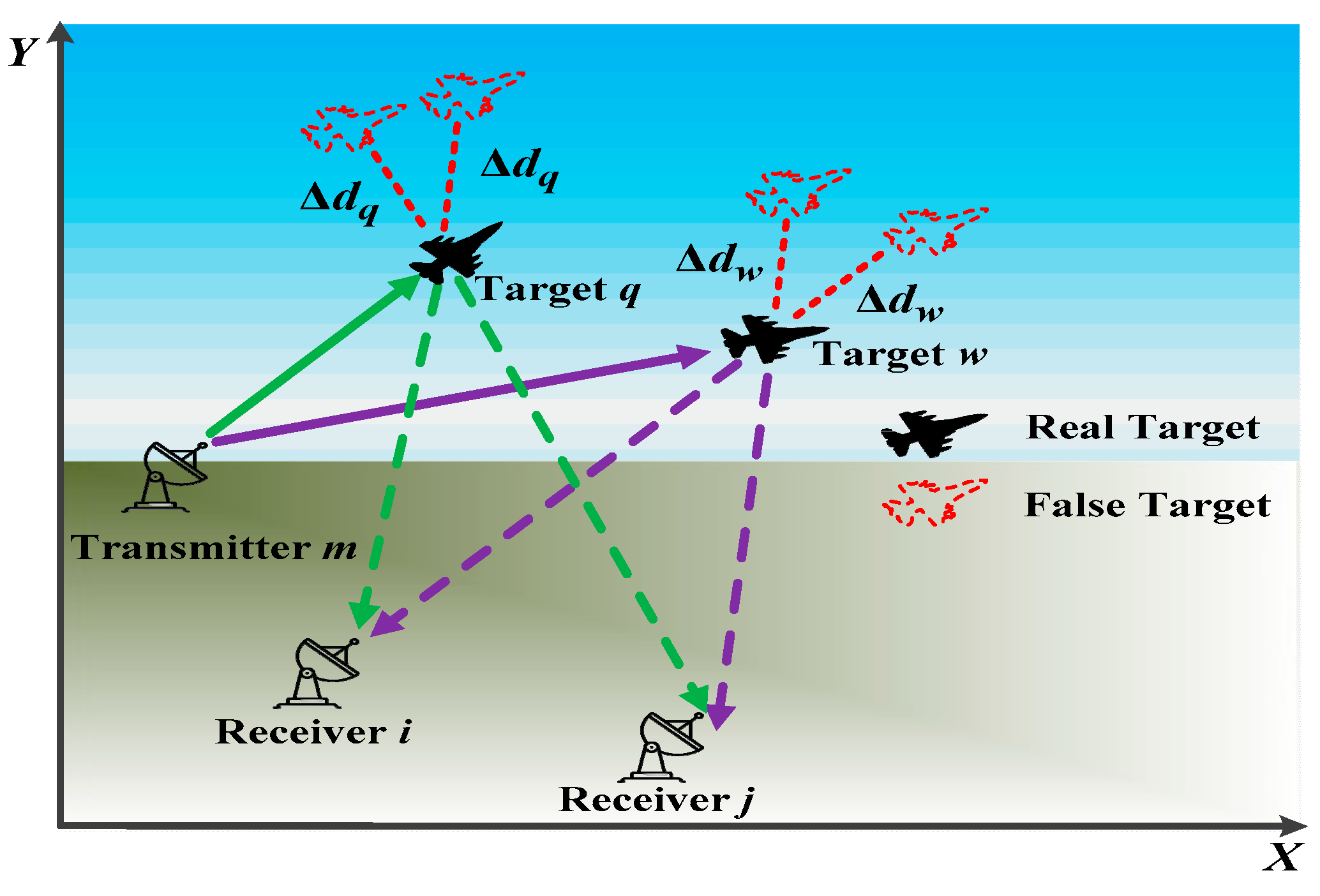
A unified resource allocation mechanism in the distributed MIMO radar under deception jamming is developed. Considering the range deception jamming environment in the mission region, we establish the system model under deception jamming and derive the CRLB for range deceptive jamming parameter estimation. In this case, an effective technique for solving radar resource management under deception jamming environment is formulated.
The paper is organized as follows. The data processing mechanism is described in Section 2. The derivation of CRLB is presented in Section 3. In Section 4, we introduce a false target discriminator and subsequently formulate the joint multi-target localization and discrimination model. Then, a three-step-based solving algorithm is given. Moreover, the experiments and results are presented in Section 5. Section 6 concludes this paper.

2. Data Processing Mechanism

Assume that the entire region of interest (ROI) exists with Q 2 targets, and each target is widely separated. We consider that a narrowband MIMO radar with distributed antennas consists of M transmit antennas and N receive antennas, and is located in Cartesian 2-D space. Denote the entire sets of transmit antennas and receive antennas by sets M = { 1 , 2 , , M } and N = { 1 , 2 , , N } , respectively. The mth transmit antenna and the nth receive antenna are located at ( x m t , y m t ) and ( x n r , y n r ) , where m M and n N . Let μ q = [ x q , y q ] T 2 denote the real position of target q, where q Q = { 1 , , Q } . Then, suppose that the targets are sufficiently dispersed, and only one target exists within each transmit beam. Hence, each transmit antenna can be used to illuminate only one target.

2.1. Signal Model

Each antenna transmits the orthogonal frequency-division multiplexing (OFDM) pulse signal [15], with a normalized equivalent s ˜ m ( t ) , which satisfies that [9]:
+ s ˜ m ( t ) s ˜ m H ( t τ ) d t = { 0 ,   m m 1 , m = m .
where m M , m M and the term of ( ) H denotes the conjugate transpose operator. To counter radar detection, the self-defense jammer equipped on the real target implements jamming by delaying and retransmitting transmit signals [16]. For the qth target which is illuminated by the mth transmit antenna, the false target can be constructed by introducing the deceptive distance Δ d q . Hence, the baseband representation of the received signal reflected by the qth target via the ( m , n ) path can be expressed as [17]:
r ˜ m , n , q ( t ) = γ m , n , q u m , q t P m t h m , n , q s ˜ m ( t τ m , n , q J ) + w ˜ m , n ( t ) ,
where u m , q t is a binary variable and is defined as:
u m , q t = { 1 ,   if   the   m th   transmit   antenna   is   selected   to   illuminate   the   q th   target 0 ,   else ,
P m t denotes the transmit power from the mth transmit antenna. The term of γ m , n , q 1 / ( R m , q t R n , q r ) 2 represents the attenuation in the signal strength due to the bistatic path loss effects. R m , q t and R n , q r denote the range from the mth transmit antenna to the qth target and the range from the nth receive antenna to the qth target, respectively. Moreover, R m , q t and R n , q r are given by:
{ R m , q t = ( x q x m t ) 2 + ( y q y m t ) 2 R n , q r = ( x q x n r ) 2 + ( y q y n r ) 2 .
Herein, h m , n , q is modeled as a known complex gain of target reflectivity. The term of w ˜ m , n ( t ) is the zero-mean white complex noise, which satisfies that w ˜ m , n ( t ) CN ( 0 , σ w ˜ 2 ) . τ m , n , q J is the superposition of the real target time-delay and the active deception time-delay, given by:
τ m , n , q J = ( R m , q t + R n , q r + Δ d q ) / c ,
where the term of c represents the speed of light. It should be noted that a real target is detected when Δ d q = 0 , while a false target is detected when Δ d q 0 . Therefore, for the same illuminated target, the spatial resolution cells (SRCs) of jamming signals and the real target echoes could be mixed in space, which is demonstrated in Figure 1.
In summary, based on the above assumptions and analysis, the intuitive process of multi-target detection in the presence of the self-defense range deception jamming signals can be shown in Figure 2.

2.2. Parameter Estimation

After obtaining the target echoes, it is necessary to extract the target measurement information by the parameter estimation method. Herein, we adopt the maximum likelihood (ML) estimation method to estimate the target parameters. Assume that all the targets are sufficiently dispersed in space, and each transmit beam only covers one target. In this case, multi-target detection problem can be converted into a series of independent single target detection problems. After signal processing and matching filtering, we can obtain an M N × 1 sampling matrix of all the receive signal from the qth target, which is given by r q = [ r 1 , 1 , q , r 2 , 1 , q , , r m , n , q , , r M , N , q ] T .
According to the receive signal model, the conditional probability density function (PDF) p ( r q | μ q ) could be calculated as:
p ( r q | μ q ) = 1 ( π σ w ˜ 2 ) M N 2 exp { 1 σ w 2 n = 1 N m = 1 M | r ˜ m , n , q ( t ) γ m , n , q u m , q t P m t h m , n , q × s ˜ m ( t τ m , n , q J ) | 2 d t } .
Then, the ML estimator for μ q can be calculated by:
{ μ ^ q } ML = arg { max μ q [ ln p ( r q | μ q ) ] } = arg { max μ q [ n = 1 N m = 1 M | r ˜ m , n , q ( t ) γ m , n , q u m , q t P m t h m , n , q s ˜ m ( t τ m , n , q J ) d t ] } .
Therefore, the location of target q can be estimated by (7). For a MIMO radar system, since a closed-form solution for (7) is not available [3], a numerical search method is required. Here, we utilize a low-complexity approximate ML estimator to obtain the exact solution to (7); the details are shown in [18].

3. Derivation of Estimation Performance Metric

Given any unbiased estimator, the CRLB can provide a tight lower bound, and has been proven to be very close to the target state estimation error on the high signal/noise ratio (SNR) condition [19]. In this section, we derive the joint CRLB of the target position integrated with the corresponding deceptive distance parameter.
Even though { μ ^ q } ML can be obtained by the ML estimation method, the estimated position vector μ ^ q could be inaccurate in the presence of the self-defense range deception jamming ( Δ d q 0 ). Moreover, in practice, this phenomenon of the mixed SRCs in Figure 1 might be interpreted as the inaccurate DOA estimation problem caused by the radar itself, e.g., receiving beamwidth and angle measuring accuracy error. In this case, it is important to evaluate the existence of deception jamming signals by estimating the deceptive distance parameter Δ d q . According to (2) and (5), we define an extended location state as η q = [ x q , y q , Δ d q ] T . In this case, the unbiased estimate of η q satisfies that [20]:
E η q [ ( η ^ q η q ) ( η ^ q η q ) T ] J - 1 ( η q ) ,
where J ( η q ) denotes the fisher information matrix (FIM), whose inverse is the CRLB, and J ( η q ) can be expressed as [11]:
J ( η q ) = E r q | η q { [ η q log p ( r q | η q ) ] [ η q log p ( r q | η q ) ] T } ,
where p ( r q | η q ) represents the conditional PDF with respect to r q under condition η q . According to (6), it can be known that p ( r q | η q ) is both an explicit function of τ m , n , q J and an implicit function of η q , where m M and n N . Then, a vector is defined as τ q J = [ τ 1 , 1 , q J , τ 2 , 1 , q J , , τ m , n , q J , τ M , N , q J ] T . Based on the chain rule, J ( η q ) can be rewritten as [21]:
J ( η q ) = Γ q J ( τ q J ) ( Γ q ) T .
Since the derive process of J ( τ q J ) can be seen in [9], it is not repeated for simplicity. The Jacobian matrix Γ q is given by:
Γ q = τ q J η q = 1 c [ a 1 , q t + a 1 , q r b 1 , q t + b 1 , q r 1 a 1 , q t + a 2 , q r b 1 , q t + b 2 , q r 1 a M , q t + a N , q r b M , q t + b N , q r 1 ] ,
where a m , q t = ( x m t x q ) / R m , q t , b m , q t = ( y m t y q ) / R m , q t , a n , q r = ( x n r x q ) / R n , q r , and b n , q r = ( y n r y q ) / R n , q r . Combined with (8)–(11), the CRLB for the qth target is expressed as:
C CRLB q ( η q , u q t , P t ) = c 2 σ w ˜ 2 8 π 2 ( m = 1 M u m , q t P m t Ψ m , q ) 1 ,
where u q t = [ u 1 , q t , u 2 , q t , , u M , q t ] T , P t = [ P 1 t , P 2 t , , P M t ] T , and Ψ m , q is a third-order square matrix. All the elements in matrix Ψ m , q are expressed as
Ψ m , q 11 = n = 1 N γ m , n , q ( β m ) 2 | h m , n , q | 2 ( a m , q t + a n , q r ) 2 Ψ m , q 22 = n = 1 N γ m , n , q ( β m ) 2 | h m , n , q | 2 ( b m , q t + b n , q r ) 2 Ψ m , q 33 = n = 1 N γ m , n , q ( β m ) 2 | h m , n , q | 2 Ψ m , q 12 = Ψ m , q 21 = n = 1 N γ m , n , q ( β m ) 2 | h m , n , q | 2 ( a m , q t + a n , q r ) ( b m , q t + b n , q r ) Ψ m , q 13 = Ψ m , q 31 = n = 1 N γ m , n , q ( β m ) 2 | h m , n , q | 2 ( a m , q t + a n , q r ) Ψ m , q 23 = Ψ m , q 32 = n = 1 N γ m , n , q ( β m ) 2 | h m , n , q | 2 ( b m , q t + b n , q r )
Herein, β m denotes the effective bandwidth of the transmit signal s ˜ m ( t ) . From (12), it should be noted that all the elements in C CRLB q are inversely proportional to transmit power P t . Moreover, since ( C CRLB q ) 1 , 1 + ( C CRLB q ) 2 , 2 σ x q 2 + σ y q 2 , where σ x q 2 and σ y q 2 represent the mean square errors (MSEs) of target q for the position estimator on the X-direction and the Y-direction. After some additional matrix manipulations, the MSE of target q for locating estimator is bounded below:
LE q ( u q t , P t ) = ( C CRLB q ) 1 , 1 + ( C CRLB q ) 2 , 2 = c 2 σ w ˜ 2 Λ q T [ Ψ q 33 ( Ψ q 11 + Ψ q 22 ) T Ψ q 13 ( Ψ q 31 ) T Ψ q 32 ( Ψ q 23 ) T ] Λ q 8 π 2 det ( Λ q T q ) .
Herein, Λ q = u q t P t , where the term of denotes the Hadamard product operator. q is defined as q = [ Ψ 1 , q , , Ψ M , q ] T , and Ψ q i J represents a M × 1 vector, which is defined as Ψ q i j = [ Ψ 1 , q i j , , Ψ M , q i j ] T , for i , j { 1 , 2 , 3 } . det ( ) is the determinant operator.

4. Optimization Model and Solution Strategy

In general, the better localization accuracy indicates a more reliable radar system in practice. In this case, to attain the higher level of localization accuracy or low probability of intercept (LPI), the radar systems aim to allocate resources in a way that maximizes localization accuracy with the given resource budget [10] or minimizes transmitter power with the constraints of predetermined target detection performance [22].
Nevertheless, in reality, the higher localization accuracy of the radar system is not always better, especially when the detected target is a false one. This phenomenon also appears in the multiple radar system, which can prevent the effectiveness of the spatial diversity gain. The process can be intuitively shown in Figure 3, in which the abbreviations of RTSRC and FTSRC denote the real target SRC and the false target SRC, respectively. As a result, when locating multiple targets, it is necessary to discriminate the authenticity of each target simultaneously in order to improve resource utilization.

4.1. False Target Discriminator

In practice, the distance spoofing parameter Δ d q is an effective basis for identifying the real target and the false target in the presence of range deception jamming [14]. In theory, with the existence of estimation errors, the estimate result of Δ d q can be seen a random variable, which satisfies that Δ d ^ q N ( Δ d q , σ Δ d q 2 ) , where σ Δ d q 2 denotes the MSE of distance spoofing estimator of the qth target. According to (12) and (13), the CRLB of σ Δ d q 2 can be computed as:
σ Δ d q 2 ( u q t , P t ) = c 2 σ w ˜ 2 Λ q T [ Ψ q 11 ( Ψ q 22 ) T Ψ q 32 ( Ψ q 21 ) T ] Λ q 8 π 2 det ( Λ q T q ) .
Based on the Neyman–Pearson theory, we utilize Δ d ^ q as the statistical discriminator, and the binary hypotheses, 0 q real target and 1 q false target, given by [14]:
0 q : Δ d ^ q 2 / σ Δ d q 2 χ 1 2 1 q : Δ d ^ q 2 / σ Δ d q 2 χ 1 2 ( Δ d q 2 / σ Δ d q 2 ) .
Herein, the term of χ 1 2 denotes the chi-square distribution with one degree of freedom, and χ 1 2 ( Δ d q 2 / σ Δ d q 2 ) represents the noncentral chi-square distribution with one degree of freedom. Assume that the expected real target’s DP is set as 𝒫 RT q = 𝒫 { 0 q | 0 q } , and then the identification threshold of the proposed discriminator is η q = χ 1 2 1 ( 𝒫 RT q ) , where χ 1 2 1 ( ) denotes the inverse cumulative distribution function of χ 1 2 . In this case, the theoretical DP of the active false target can be expressed as:
𝒫 FT q ( u t q , P t ) | η q = 𝒫 { 1 q | 1 q } = 1 χ 1 2 ( Δ d q 2 / σ Δ d q 2 ) ( η q ) ,
where χ 1 2 ( Δ d q 2 / σ Δ d q 2 ) ( η q ) is the cumulative distribution of χ 1 2 .

4.2. Problem Formulation

Due to the effect of the range deception jamming signal, radar should consider both target localization accuracy and the relevant DP. In this case, in the detection process for the qth target, LE q and 𝒫 FT q must be taken into account in guiding resource allocation. Theoretically, the value ranges of LE q and 𝒫 FT q are [ 0 , + ] and [ 0 , 1 ] , respectively. Since they have different dimensions, it is difficult to discuss the localization performance and the discrimination performance under the same framework.
To balance the effects of different dimensions of the two performance parameters, we introduce a nondimensionalization mechanism. The specific calculation process is given as follows:
Step 1: Let LE q [ 0 , max ] , for q Q . Herein, max is a given upper bound, which is computed by max = max q = 1 , 2 , , Q { LE q ( 1 M T , P min t ) } , where the vector P min t = [ P min , 1 t , P min , 2 t , , P min , M t ] T denotes the minimum power required to maintain the essential signal-to-noise ratio (SNR) condition for detecting the target.
Step 2: Let ˜ LE q = LE q / max , for q Q . In this case, the normalized CRLB of the localization estimation satisfies that ˜ LE q [ 0 , 1 ] , for q Q .
Step 3: Considering that the localization performance is better when the value of ˜ LE q is smaller, while radar the discrimination performance improves with a larger 𝒫 FT q . In this case, we reset 𝒫 FT q is as 𝒫 ˜ FT q = 1 𝒫 FT q , thus 𝒫 ˜ FT q [ 0 , 1 ] , for q Q .
After that, the optimization model for localization accuracy and DP can be developed. For the multi-target scenario, the overall performance is considered in this paper, thus the objective function of antenna selection and power allocation can be expressed as:
F ( U t , P t ) = q = 1 Q { ς q ˜ LE q ( u t q , P t ) + ϖ q 𝒫 ˜ FT q ( u t q , P t ) } .
The terms of ς q and ϖ q jointly constitute the task assignment result for the qth target, and are defined as:
ς q = { 1 ,   if   𝒫 FT q ( u t q , P t ) 𝒫 FT , min 0 ,   esle ,
ϖ q = { 1 ,   if   𝒫 FT , min 𝒫 FT q ( u t q , P t ) 𝒫 FT , max 0 ,   esle ,
where 𝒫 FT , max and 𝒫 FT , min are the preset threshold values of DP in the radar system, i.e., the qth target is judged as a false target when 𝒫 FT q ( u t q , P t ) 𝒫 FT , max , and target q is declared true when 𝒫 FT q ( u t q , P t ) 𝒫 FT , min . In this case, we can make the radar system simultaneously complete the localization of the real target and the discrimination of the target with a risk of fake, and consequently abandon the false target. Moreover, in (18), U t is given by:
U t = [ ( u 1 t ) T ( u q t ) T ( u Q t ) T ] = [ u 1 , 1 t u 2 , 1 t u M , 1 t u 1 , q t u 2 , q t u M , q t u 1 , Q t u 2 , Q t u M , Q t ] = [ u 1 t u 2 t u M t ] ,
where u m t = [ u m , 1 t , u m , , 2 t , , u t m , Q t ] T denotes the results of antenna selection for the mth transmit antenna, for m M . However, due to the limited data transmission rate and the given bandwidth available for communication [23], the antenna selection problem should be constrained. Moreover, in order to obtain the DP of each target, it is necessary to ensure that each target is illuminated by at least two transmit antennas. In theory, to maintain each transmit antenna can work in a stable working mode and satisfy the power budget, the transmit power results also need to be restricted. According to the aforesaid analysis, the optimization formulation can be expressed as:
min F ( U t , P t ) s . t .   1 Q T u m t = 1 ,   1 1 M T u q t L       1 Q T Λ t 1 M = P total , u m , q t { 0 , 1 }       { P min , m t P m t P max , m t ,   if   u m t 0 P m t = 0 ,   else       ς q = { 1 ,   if   𝒫 FT q ( u q t , P t ) 𝒫 FT , min 0 ,   esle       ϖ q = { 1 ,   if   𝒫 FT , min 𝒫 FT q ( u q t , P t ) 𝒫 FT , max 0 ,   esle       q Q , m M  
where the term of L ( Q L M ) represents the maximum of transmit antennas that can be selected to detect one target, and the matrix Λ t = [ Λ 1 t , , Λ Q t ] T = [ u 1 t P t , , u Q t P t ] T . P max t = [ P max , 1 t , P max , 2 t , , P max , M t ] T denotes the maximum values and the minimum values of transmit power in each transmit antenna, and P total is the total transmit power budget.
The first line constraints in (22) imply that the three constraints on transmit antenna selection, i.e., each target is illuminated by at least one transmitted beam, each transmitted beam covers only one target, and at most L transmit antennas are selected to participate in the detection mission. The second line constraints represent that the transmit power is bounded by a power budget and the antenna selection variable is binary. Moreover, the third line constraints indicate that if u t m 0 , the corresponding transmit power satisfies with P min , m t P m t P max , m t , otherwise, P t m = 0 , for q Q , m M .

4.3. Solution Strategy

In mathematics, although the previous multi-objective optimization problem has been transformed into a single-objective optimization problem after the utilization of the nondimensionalization mechanism, (22) is still difficult to solve for the following reasons: (1) Due to the introduction of the task assignment parameters and the hypothesis testing process, the objective function is nonlinear and non-convex; (2) U t is a binary matrix; and (3) U t and P t are coupled and always appear in product form. In this case, (22) is very tricky to solve, and it takes too much time to obtain the global optimal solution by using the exhaustive search algorithm [11], especially in the large-scale antenna systems [6]. In order to solve (22), a three-step solver is proposed to find a suboptimal solution. If we suppose that q Q and m M , the detailed steps are given as follows:
Step 1: Reformulation and relaxation. Since u t q and P t are always coupled as u m , q t P m t in (12)–(15), we introduce an auxiliary variable ξ m , q t = u m , q t P m t . By combining it with the corresponding matrix ξ t = Λ t , we can reformulate (22) as:
min   F ( ξ t ) s . t .   1 Q T ξ t 1 M = P total ,   u m , q t { 0 , 1 }         1 Q T u m t = 1 , 1 1 M T u q t L       { P min , m t P m t P max , m t ,   if   u m t 0 P m t = 0 , else       ς q = { 1 ,   if   𝒫 FT q ( u q t , P t ) 𝒫 FT , min 0 ,   esle       ϖ q = { 1 ,   if   𝒫 FT , min 𝒫 FT q ( u q t , P t ) P FT , max 0 ,   esle
However, since (23) contains non-linear and non-convex constraints, and it is still difficult to solve. We further relax (23) as:
min   F ( ξ t ) s . t .   1 Q T ξ t 1 M = P total ,   0 ξ m , q t P max , m t       ς q = { 1 ,   if   𝒫 FT q ( u q t , P t ) 𝒫 FT , min 0 ,   esle       ϖ q = { 1 ,   if   𝒫 FT , min 𝒫 FT q ( u q t , P t ) 𝒫 FT , max 0 ,   esle
Similar with [24], (24) can be easily solved by the PSO algorithm. For simplicity, the details of the PSO algorithm are omitted and can be seen in [24]. In addition, it is worth noting that because the solution of (24) is based on the assumption that all targets are illuminated by all transmit antennas, the solution ξ t , opt cannot be directly taken as the result of the original resource allocation problem. In this case, ξ t , opt should be further processed based on the transmit antenna selection constraints in (23).
Step 2: Transmit antenna selection based on the results of (24). We normalize the optimal transmit power of each transmit antenna as ζ m , q , opt t = ξ m , q , opt t / P total , and arrange the normalized transient results ζ t , opt = { ζ m , q , opt t | m M , q Q } from the highest to the lowest. Then, sorting out the transmit antenna sequence corresponding to the maximum value of ξ m , q , opt t with the constraints in the second line of (23). The process of the sorting algorithm is shown in Algorithm 1.
Step 3: Power resource optimal allocation for a given budget. Firstly, we optimize the allocation of transmit power based on the transmit antenna selection results obtained by the sorting algorithm. For a fixed optimal antenna selection matrix U t , opt , the rest problem of (22) can be expressed as:
min F ( P t ) | U t , opt s . t .   1 M T P t = P total , { P min , m t P m t P max , m t ,   if   u m t 0 P m t = 0 ,   else       ς q = { 1 ,   if   𝒫 FT q ( u q t , P t ) 𝒫 FT , min 0 ,   esle       ϖ q = { 1 ,   if   𝒫 FT , min 𝒫 FT q ( u q t , P t ) 𝒫 FT , max 0 ,   esle
Hence, similar with (24), by utilizing the PSO algorithm, the optimal power allocation results P t , opt can be achieved through solving (25). Up to now, we have obtained the suboptimal solutions for the joint transmit antenna selection and power allocation in (22).
Algorithm 1. Sorting algorithm for the transmit antenna selection.
Remotesensing 14 03904 i001

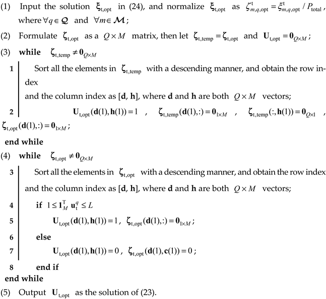
5. Experiments and Results

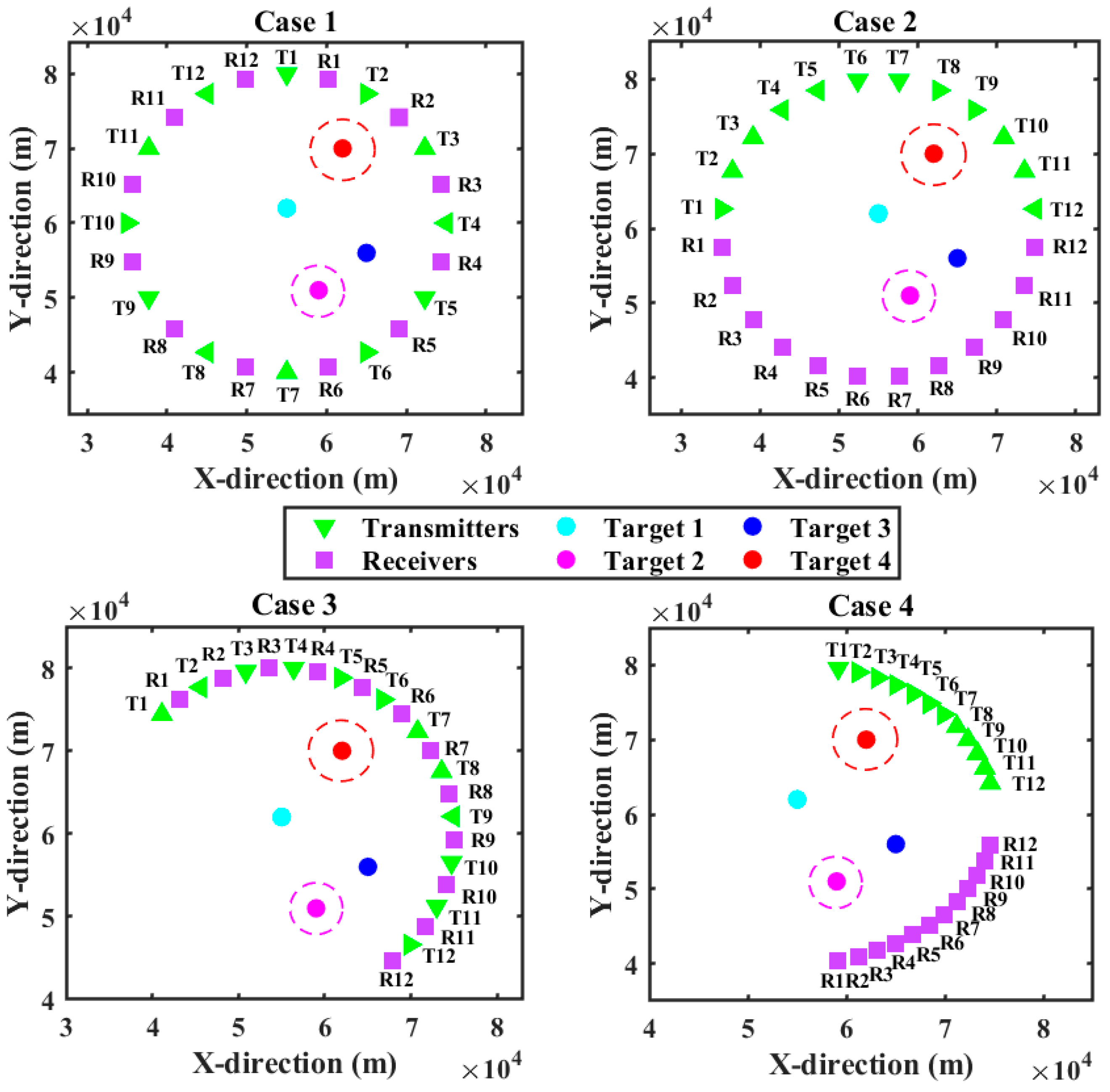
5.1. Parameter Designation

In this section, a distributed MIMO radar system with M = 12 transmit antennas and N = 12 receive antennas is chosen for analysis. In the ROI, there are Q = 4 targets widely distributed and the state parameters of each target are shown in Table 1. To demonstrate the performance of the proposed strategy under different antenna deployment, four different antenna topologies are herein taken into consideration. As such, the four different geometric relationships between the distributed MIMO radar systems and targets are demonstrated in Figure 4. For the radar system, the effective bandwidth is β m = 1 MHz and the effective time duration is T m = 1 ms for m = 1 , 2 , , M . Furthermore, the maximum quantity of transmit antennas that can be selected to illuminate one target is set as L = 6 . The bounds for transmit power are P max , m t = 0.3 P total and P min , m t = 0.05 P total for m = 1 , 2 , , M , and the total transmit power budget P total = 100 kW. The SNR is set as 10 dB at the distance of 20 km, with the baseline measurement error R 0 = diag ( 50 2 , 0 . 1 2 ) . In the PSO algorithm framework, we set the particle number N p = 50 , the inertia weight W i = 1 , the acceleration factors c 1 = c 2 = 0.8 , and the maximum iteration number L max = 50 . The upper and lower bounds of the preset threshold of DP are separately set as 𝒫 FT , max = 0.8 and 𝒫 FT , min = 0.3 . According to (2), it can be seen that the error of a fixed receiver comes from the zero-mean Gaussian white noise in the echo signals. Therefore, in order to possibly eliminate the effect of measurement errors on the validation of the proposed model, the Monte Carlo method is adopted in the numerical experiment in this section. Without loss of generality, the number of Monte Carlo trails is set as N sim = 100 .

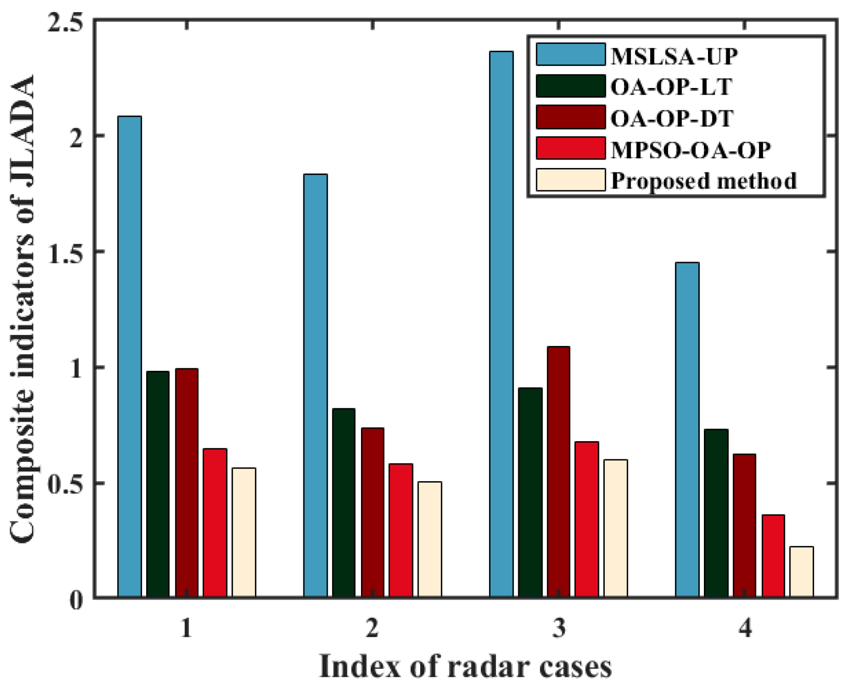
5.2. Effectiveness of the Proposed Solver

The results of transmit antenna selection and power allocation under four different cases are given in Figure 5. Herein, the color in each rectangle represents the ratio of allocated power r m , q power = ξ m , q t / P total , for m = 1 , 2 , , M , and q = 1 , 2 , , Q . In particular, the indigo blue color indicates the ratio r m , q power = 0 , which means that the mth transmit antenna is not selected for illuminating the qth target. Meanwhile, the crimson color denotes that the ratio achieves the maximum. In addition, the results of task assignment and DP for each target under four different cases are shown in Table 2.
As can be seen from Table 2 that target 3 is assigned as the target to be located in each of the four cases because it has good observation conditions and is not covered by the distance deception signals. In addition, since both target 2 and target 4 transmit distance deceptive jamming signals, one of the targets between target 2 and target 4 in case 1, case 2, and case 3 is defined as a false target, while the other target is assigned to discrimination task. In particular, target 2 and target 4 are defined as false targets in case 4 due to the closer observation distances. As for target 1, since its position is near the center of the radar antennas in case 1 and case 2, better observation conditions are available and the DPs with respect to target 1 are lower. In this case, target 1 is judged to be a true target and the localization task is performed both in case 1 and case 2. Moreover, since target 1 is located far away from the radar antennas in case 3 and case 4, the relevant measurement error increases, resulting in an increase in DP values.
In order to demonstrate the effectiveness of the proposed algorithm, the following three benchmarks are used for comparison:
(1)
Multi-start local search [25] antenna selection with uniform power allocation (MSLSA-UP). This algorithm selects active transmit antennas by adopting the multi-start local search algorithm and allocates the transmit power resource to those selected active transmit antennas uniformly.
(2)
Optimal antenna selection with optimal power allocation for localization task (OA-OP-LT). In this algorithm, we consider the localization task, and the task assignment parameters in (22) are set as ς q = 1 and ϖ q = 0 , for q Q . Then, the proposed solving strategy is utilized to solve the modified optimization model, and the optimal transmit antenna selection and power allocation results can be obtained.
(3)
Optimal antenna selection with optimal power allocation for discrimination task (OA-OP-DT). This algorithm focuses exclusively on discrimination task, and we set ς q = 0 and ϖ q = 1 , for q Q . Similar with the OA-OP-LT algorithm, the optimization model is then solved by the proposed solving strategy.
(4)
Modified PSO (MPSO) [26] based optimal antenna selection with optimal power allocation (MPSO-OA-OP). By Combining the MPSO algorithm and the optimization model in (22), this algorithm solves the transmit antenna selection problem and the power allocation problem simultaneously.
The above four benchmark algorithms are compared with our proposed algorithm in terms of the composite indicator of joint localization accuracy and discrimination ability (JLADA). To be specific, the results of resource allocation by using the four benchmark algorithms are substituted into the model established in this paper, and then the objective function values in (18) are calculated under the constraints of the binary judgments of (19) and (20). The comparative analysis of composite indicators of JLADA based on different resource allocation strategies is demonstrated in Figure 6.
It shows in Figure 6 that the proposed method performs best in improving localization accuracy and discrimination ability under the four different radar layouts cases. To be specific, the performances of the OA-OP-LT algorithm and the OA-OP-DT algorithm are similar, which also indicates the correctness of the nondimensionalization mechanism and the normalized model proposed in this paper, i.e., the localization task and discrimination task are equally important in our resource allocation scheme. Moreover, the performance comparison between the MPSO-OA-OP algorithm and the proposed method shows that the proposed two-step solving strategies has good solving ability.

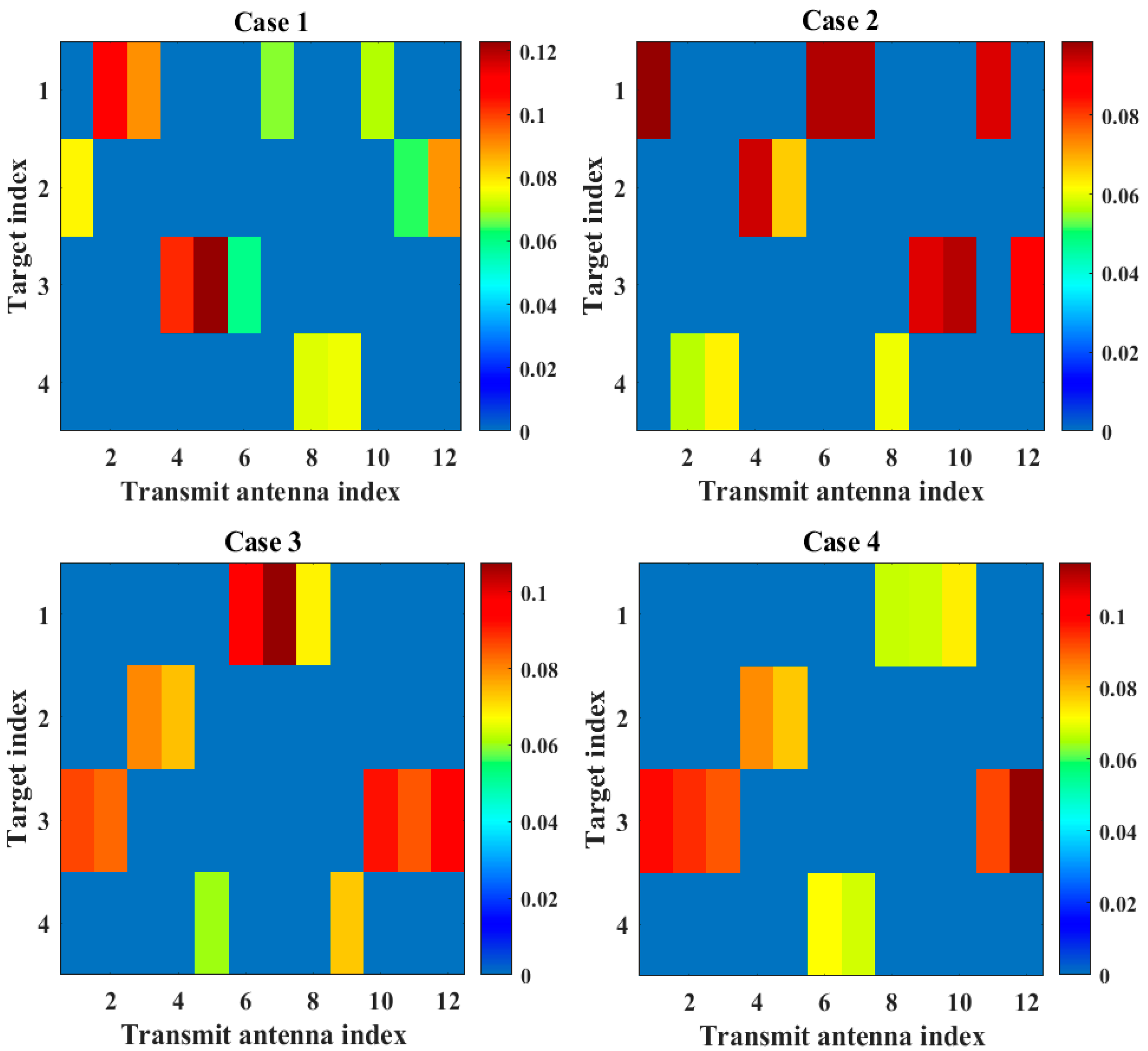
5.3. Validity Analysis of the Proposed Model

In order to analyze localization error in the simulation results, according to the task assignment results in Table 2, the CRLBs of localization estimate error for all the located targets under four cases are given. To evaluate the localization performance in addition to the CRLB, the MSE under Monte Carlo trails is introduced, given by:
M S E q = 1 N sim i = 1 N sim [ ( x q x ^ q i ) 2 + ( y q y ^ q i ) 2 ]
where ( x ^ q i , y ^ q i ) denotes the position estimate for the qth target in the ith trail. Specifically, in case 1, since target 1 and target 3 are assigned to be located, the corresponding CRLBs of the two targets are LE 1 ( u 1 , opt t , P t , opt ) = 46.8 m2 and LE 3 ( u 3 , opt t , P t , opt ) = 149.6 m2, while the MSEs are M S E 1 = 67.2 m2 and M S E 3 = 178.5 m2. The CRLBs for target 1 and target 3 in case 2 are LE 1 ( u 1 , opt t , P t , opt ) = 203.2 m2 and LE 3 ( u 3 , opt t , P t , opt ) = 87.5 m2, and the relevant MSEs are M S E 1 = 238.4 m2 and M S E 3 = 105.6 m2. Since only target 3 is assigned to be located in case 3, the CRLB and the MSE of target 3 are LE 3 ( u 3 , opt t , P t , opt ) = 126.4 m2 and M S E 3 = 148.1 m2. In case 4, the CRLB and the MSE of target 3 are LE 3 ( u 3 , opt t , P t , opt ) = 75.9 m2 and M S E 3 = 103.5 m2, respectively. In conclusion, from the perspective of localization errors, the proposed model can effectively improve the target localization accuracy by allocation resources compared to the measurement errors.
For the error analysis of the proposed discriminator, it can be seen from Table 1 that target 2 and target 4 are preset as false targets in the simulation. Since the existence of deception distance in target 2 and target 4, the fixed radar system tends to obtain higher DPs for the two targets in the same observation condition. From the simulation results in Tab 3, by utilizing the resource optimal allocation scheme, both target 2 and target 4 can be accurately identified as false targets in case 4. In addition, one of the two targets can be accurately identified under case 1 to case 3, while a higher DP is prompted for the other false target and the subsequent discrimination task is assigned. Thus, the correctness of the proposed discriminator can be proven from the identification results in a global perspective.

6. Conclusions and Future Work

In this paper, to deal with deception jamming in the distributed MIMO radar, we formulate an optimization model of transmit antenna selection and power allocation for joint multi-target localization and discrimination. By utilizing the relaxation technique and the PSO algorithm, a three-step solving algorithm is developed for this optimization problem. Numerical simulations demonstrate that the proposed strategy under the joint localization and discrimination task conditions can improve comprehensive performance by more than 30% compared with single task conditions in four different radar layouts cases. In addition, based on the proposed resource optimal algorithm, the composite indicators of JLADA can decrease more than 70% compared with the uniform allocation scheme. The main innovation of the proposed algorithm is the establishment of a unified optimization model of joint multi-target localization and discrimination under deception jamming. However, by artificially transforming the multi-objective optimization problem into the single-objective optimization problem, the model error in this paper is inevitable. Moreover, although the proposed solution strategy is effective, the global optimal solution still cannot be obtained due to the relaxation processing.
In this case, the future research direction will be to directly solve the initial multi-objective optimization problem, and discuss and use more efficient solving algorithms. Moreover, in the future work, we will further add scenarios, including target RCS time-varying, angle scintillation noise, and distance spoofing noise time-varying to verify the proposed algorithm; more quantitative analysis links will also be added.

Author Contributions

Conceptualization, Z.L. and W.L.; methodology, H.Z.; software, Z.L.; validation, J.X.; formal analysis, investigation, Z.L.; resources, data curation, J.X.; writing—original draft preparation, Z.L.; writing—review and editing, Z.L. and H.Z.; visualization, Z.L. and H.X.; supervision, W.L.; project administration, J.X.; funding acquisition, W.L. and H.Z. All authors have read and agreed to the published version of the manuscript.

Funding

This work was supported by National Natural Science Foundation of China under Grants 62001506 and 62071482.

Data Availability Statement

Not applicable.

Acknowledgments

The authors would like to thank the editors and all the reviewers for their very valuable and insightful comments during the revision of this work.

Conflicts of Interest

The authors declare no conflict of interest.

References

  1. Yan, J.K.; Pu, W.Q.; Zhou, S.H.; Liu, H.W.; Bao, Z. Collaborative detection and power allocation framework for target tracking in multiple radar system. Inf. Fusion. 2020, 55, 173–183. [Google Scholar] [CrossRef]
  2. Rabideau, D.J.; Parker, P. Ubiquitous MIMO Multifunction Digital Array Radar and the Role of Time-Energy Management in Radar; MIT Lincoln Laboratory: Lexington, MA, USA, 2003. [Google Scholar]
  3. Xie, M.C.; Yi, W.; Kong, L.J.; Kirubarajan, T. Receive-beam resource allocation for multiple target tracking with distributed MIMO Radars. IEEE Trans. Aerosp. Electron. Syst. 2018, 54, 2421–2436. [Google Scholar] [CrossRef]
  4. Zheng, G.M.; Song, Y.W.; Chen, C. Height measurement with meter wave polarimetric MIMO radar: Signal model and music-like algorithm. Signal Process. 2022, 190, 108344. [Google Scholar] [CrossRef]
  5. Zhang, W.W.; Shi, C.G.; Salous, S.; Zhou, J.J.; Yan, J.K. Convex optimization-based power allocation strategies for target localization in distributed Hybrid non-coherent active-passive radar networks. IEEE Trans. Signal Process. 2022, 70, 2476–2488. [Google Scholar] [CrossRef]
  6. Zhang, H.W.; Liu, W.J.; Xue, J.W.; Zhang, Z.J.; Lu, W.L. Joint subarray selection and power allocation for cognitive target tracking in large-scale MIMO radar networks. IEEE Syst. J. 2020, 14, 2569–2580. [Google Scholar] [CrossRef]
  7. Radmard, M.; Chitgarha, M.M.; Majd, M.N.; Nayebi, M.M. Antenna placement and power allocation optimization in MIMO detection. IEEE Trans. Aerosp. Electron. Syst. 2014, 50, 1468–1478. [Google Scholar] [CrossRef]
  8. Gao, H.; Wang, J.; Jiang, C.X.; Zhang, X.D. Antenna allocation in MIMO radar with widely separated antennas for multi-target detection. Sensors 2014, 14, 20165–20187. [Google Scholar] [CrossRef] [PubMed]
  9. Godrich, H.; Petropulu, A.P.; Poor, H.V. Power allocation strategies for target localization in distributed multiple-radar architectures. IEEE Trans. Signal Process. 2011, 59, 3226–3240. [Google Scholar] [CrossRef]
  10. Garcia, N.; Haimovich, A.M.; Coulon, M.; Lopts, M. Resource allocation in MIMO radar with multiple targets for non-coherent localization. IEEE Trans. Signal Process. 2014, 62, 2656–2666. [Google Scholar] [CrossRef]
  11. Zhang, W.W.; Shi, C.G.; Zhou, J.J. Power minimization-based joint resource allocation algorithm for target localization in non-coherent distributed MIMO radar system. IEEE Syst. J. 2022, 16, 2183–2194. [Google Scholar] [CrossRef]
  12. Xie, M.C.; Yi, W.; Kirubarajan, T.; Kong, L.J. Joint node selection and power allocation strategy for multitarget tracking in decentralized radar networks. IEEE Trans. Signal Process. 2018, 66, 729–743. [Google Scholar] [CrossRef]
  13. Chen, Y.J.; Zhang, Q.; Luo, Y.; Li, K.M. Multi-target radar imaging based on phased-MIMO technique-Part P: Adaptive resource allocation. IEEE Sens. J. 2017, 17, 6198–6209. [Google Scholar] [CrossRef]
  14. Zhao, S.S.; Liu, Z.W. Deception parameter estimation and discrimination in distributed multiple-radar architectures. IEEE Sens. J. 2017, 17, 6322–6330. [Google Scholar] [CrossRef]
  15. Ahmed, A.; Zhang, Y.D.; Hassanien, A. Joint radar-communications exploiting optimized OFDM waveforms. Remote Sens. 2021, 13, 4376. [Google Scholar] [CrossRef]
  16. Zhang, S.Y.; Zhou, Y.; Zhang, L.R.; Zhang, Q.Y.; Du, L. Target detection for multistatic radar in the presence of deception jamming. IEEE Sens. J. 2021, 21, 8130–8141. [Google Scholar] [CrossRef]
  17. Ma, B.T.; Chen, H.W.; Sun, B.; Xiao, H.T. A joint scheme of antenna selection and power allocation for localization in MIMO radar sensor networks. IEEE Commun. Lett. 2014, 18, 2225–2228. [Google Scholar] [CrossRef]
  18. Wang, X.; Hu, B. A low-complexity ML estimator for carrier and sampling frequency offsets in OFDM systems. IEEE Commun. Lett. 2014, 18, 503–506. [Google Scholar] [CrossRef]
  19. Godrich, H.; Haimovich, A.M.; Blum, R.S. Target localization accuracy gain in MIMO radar-based systems. IEEE Trans. Inf. Theory 2010, 56, 2783–2803. [Google Scholar] [CrossRef]
  20. Zhang, H.W.; Liu, W.J.; Zong, B.F.; Shi, J.P.; Xie, J.W. An efficient power allocation strategy for maneuvering target tracking in cognitive MIMO radar. IEEE Trans. Signal Process. 2021, 69, 1591–1602. [Google Scholar] [CrossRef]
  21. Yan, J.K.; Pu, W.Q.; Liu, H.W.; Jiu, B.; Bao, Z. Robust chance constrained power allocation scheme for multiple target localization in MIMO radar system. IEEE Trans. Signal Process. 2018, 66, 3946–3957. [Google Scholar] [CrossRef]
  22. Shi, C.G.; Wang, F.; Sellathurai, M.; Zhou, J.J.; Salous, S. Low probability of intercept-based optimal power allocation scheme for an integrated multistatic radar and communication system. IEEE Syst. J. 2020, 14, 983–994. [Google Scholar] [CrossRef]
  23. Yan, J.K.; Liu, H.W.; Pu, W.Q.; Zhou, S.H.; Liu, Z.; Bao, Z. Joint beam selection and power allocation for multiple target tracking in netted colocated MIMO radar system. IEEE Trans. Signal Process. 2016, 64, 6417–6427. [Google Scholar] [CrossRef]
  24. Shi, C.; Wang, Y.; Salous, S.; Zhou, J.; Yan, J. Joint transmit resource management and waveform selection strategy for target tracking in distributed phased array radar network. IEEE Trans. Aerosp. Electron. Syst. 2021, 58, 2762–2778. [Google Scholar] [CrossRef]
  25. Godrich, H.; Petropulu, A.P.; Poor, H.V. Sensor selection in distributed multiple-radar architectures for localization: A knapsack problem formulation. IEEE Trans. Signal Process. 2012, 60, 247–260. [Google Scholar] [CrossRef]
  26. Zhang, H.W.; Xie, J.W.; Shi, J.P.; Zhang, Z.J.; Fu, X.L. Sensor scheduling and resource allocation in distributed MIMO radar for joint target tracking and detection. IEEE Access 2019, 7, 62387–62400. [Google Scholar] [CrossRef]
Figure 1. Diagram of the SRCs with target echoes and jamming signals.
Remotesensing 14 03904 g001
Figure 2. Intuitive process of multi-target detection under self-defense range deception jamming.
Remotesensing 14 03904 g002
Figure 3. Target detection mechanism under range deception jamming.
Remotesensing 14 03904 g003
Figure 4. Four different multiple radar layouts with multiple target locations.
Remotesensing 14 03904 g004
Figure 5. Transmit antenna selection and power allocation results under four cases.
Remotesensing 14 03904 g005
Figure 6. Comparisons of composite indicators of JLADA using different algorithms.
Remotesensing 14 03904 g006
Table 1. The target parameters of each target.
Target IndexTarget 1Target 2Target 3Target 4
Position (km)(55,62)(59,51)(65,56)(62,70)
RCS (m2)1111
Deception distance (km)01.502.5
Table 2. The results of task assignment and DP for each target under four cases.
Case 1Target 1Target 2Target 3Target 4Case 2Target 1Target 2Target 3Target 4
ς q 1010 ς q 1010
ϖ q 0100 ϖ q 0100
DP0.140.720.120.85DP0.070.740.160.92
Case 3Target 1Target 2Target 3Target 4Case 4Target 1Target 2Target 3Target 4
ς q 0010 ς q 0010
ϖ q 1001 ϖ q 1000
DP0.480.880.110.74DP0.730.870.130.88
Publisher’s Note: MDPI stays neutral with regard to jurisdictional claims in published maps and institutional affiliations.

