
An Overview on Down-Looking UAV-Based GPR Systems

 , ,
, ,  ,
,  ,
,  ,
,  and
and 
Abstract
:1. Introduction
2. State-of-the-Art Down-Looking UAV-Based GPR Systems
3. Practical Issues and Technical Challenges for High-Resolution Imaging
3.1. UAV Constraint
3.2. UAV Flight Dynamics
3.3. Clutter
4. Applications
4.1. Surface Object Detection
4.2. Landmine Detection
4.3. Soil Moisture Mapping
4.4. Snowpack Stratigraphy and Search Rescue
5. GPR Data-Processing Approaches
- standard processing;
- advanced imaging/focusing algorithms.
5.1. Standard Processing
5.2. Advanced Imaging/Focusing Algorithms
6. Experimental Tests
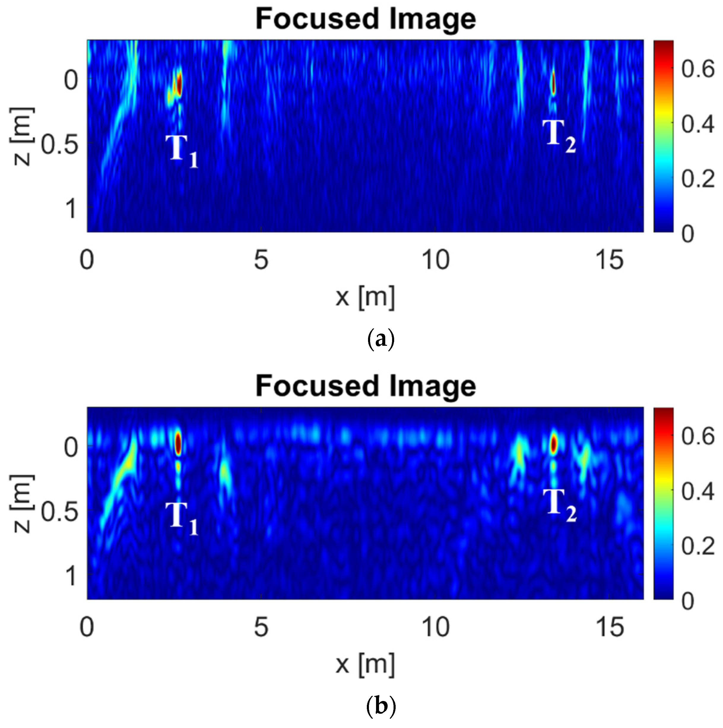
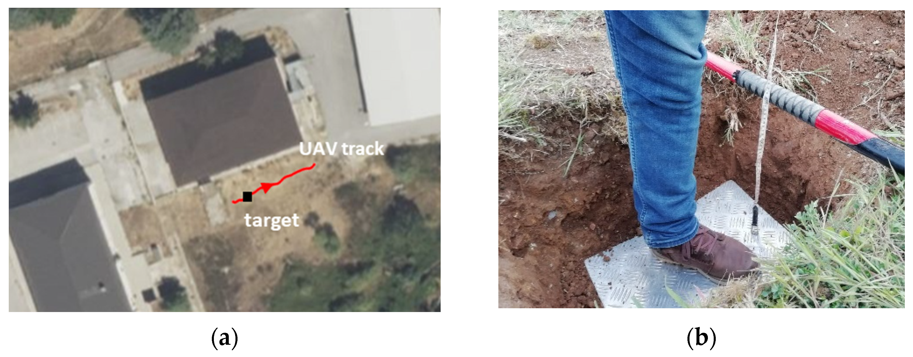
6.1. Surface Imaging Example
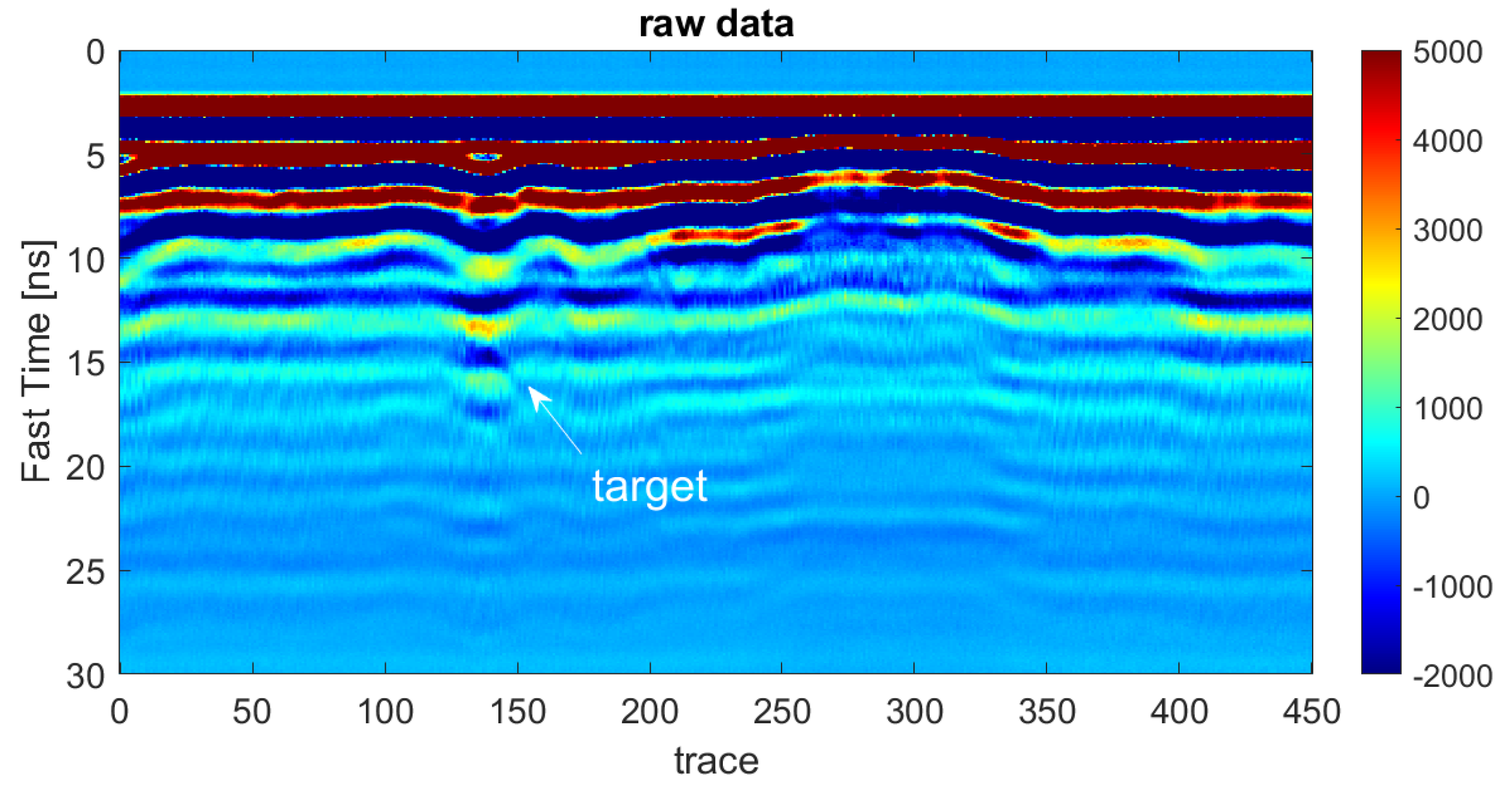
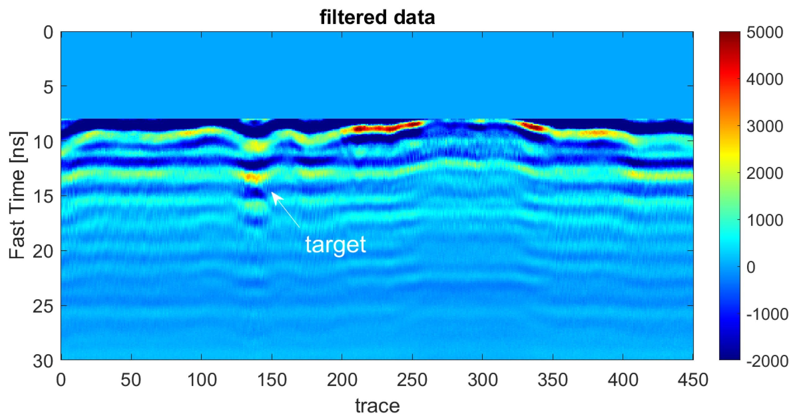
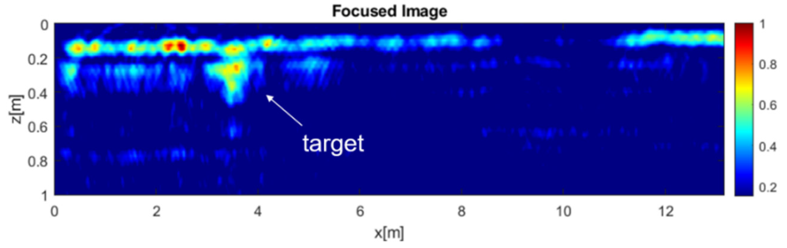
6.2. Subsurface Imaging Example
7. Discussion and Future Perspectives
Author Contributions
Funding
Acknowledgments
Conflicts of Interest
References
- Floreano, D.; Wood, R.J. Science, technology and the future of small autonomous drones. Nature 2015, 521, 460–466. [Google Scholar] [CrossRef] [Green Version]
- Daniels, D.J. Ground Penetrating Radar; IET: London, UK, 2004. [Google Scholar]
- Weib, M.; Ender, J.H.G. A 3D Imaging Radar for Small Unmanned Airplanes-ARTINO. In Proceedings of the European Radar Conference, Paris, France, 3–4 October 2005; pp. 209–212. [Google Scholar]
- Li, C.J.; Ling, H. High-resolution, downward-looking radar imaging using a small consumer drone. In Proceedings of the 2016 IEEE International Symposium on Antennas and Propagation (APSURSI), Fajardo, PR, USA, 26 June–1 July 2016; pp. 2037–2038.
- Colorado, J.; Perez, M.; Mondragon, I.; Mendez, D.; Parra, C.; Devia, C.; Moritz, M.; Neira, L. An integrated aerial system for landmine detection: SDR-based Ground Penetrating Radar onboard an autonomous drone. Adv. Robot. 2017, 31, 791–808. [Google Scholar] [CrossRef]
- Burr, R.; Schartel, M.; Schmidt, P.; Mayer, W.; Walter, T.; Waldschmidt, C. Design and Implementation of a FMCW GPR for UAV-based Mine Detection. In Proceedings of the 2018 IEEE MTT-S International Conference on Microwaves for Intelligent Mobility (ICMIM), Munich, Germany, 15–17 April 2018; pp. 1–4. [Google Scholar]
- Burr, R.; Schartel, M.; Grathwohl, A.; Mayer, W.; Walter, T.; Waldschmidt, C. UAV-Borne FMCW InSAR for Focusing Buried Objects. IEEE Geosci. Remote Sens. Lett. 2021, 19, 4014505. [Google Scholar] [CrossRef]
- Jenssen, R.O.R.; Eckerstorfer, M.; Jacobsen, S. Drone-mounted ultrawideband radar for retrieval of snowpack properties. IEEE Trans. Instrum. Meas. 2019, 69, 221–230. [Google Scholar] [CrossRef] [Green Version]
- Garcia-Fernandez, M.; López, Y.Á.; Arboleya, A.A.; Valdés, B.G.; Vaqueiro, Y.R.; Andrés, F.L.H.; García, A.P. Synthetic aperture radar imaging system for landmine detection using a ground penetrating radar on board a unmanned aerial vehicle. IEEE Access 2018, 6, 45100–45112. [Google Scholar] [CrossRef]
- Garcia-Fernandez, M.; Alvarez-Lopez, Y.; Las Heras, F. Autonomous Airborne 3D SAR Imaging System for Subsurface Sensing: UWB-GPR on Board a UAV for Landmine and IED Detection. Remote Sens. 2019, 11, 2357. [Google Scholar] [CrossRef] [Green Version]
- Ludeno, G.; Catapano, I.; Renga, A.; Vetrella, A.; Fasano, G.; Soldovieri, F. Assessment of a micro-UAV system for microwave tomography radar imaging. Remote Sens. Environ. 2018, 212, 90–102. [Google Scholar] [CrossRef]
- Noviello, C.; Esposito, G.; Catapano, I.; Soldovieri, F. Multilines Imaging Approach for Mini-UAV Radar Imaging System. IEEE Geosci. Remote Sens. Lett. 2021, 19, 3507105. [Google Scholar] [CrossRef]
- Noviello, C.; Esposito, G.; Fasano, G.; Renga, A.; Soldovieri, F.; Catapano, I. Small-UAV Radar Imaging System Performance with GPS and CDGPS Based Motion Compensation. Remote Sens. 2020, 12, 3463. [Google Scholar] [CrossRef]
- Catapano, I.; Gennarelli, G.; Ludeno, G.; Noviello, C.; Esposito, G.; Renga, A.; Fasano, G.; Soldovieri, F. Small Multicopter-UAV-Based Radar Imaging: Performance Assessment for a Single Flight Track. Remote Sens. 2020, 12, 774. [Google Scholar] [CrossRef] [Green Version]
- Schreiber, E.; Heinzel, A.; Peichl, M.; Engel, M.; Wiesbeck, W. Advanced buried object detection by multichannel, UAV/drone carried synthetic aperture radar. In Proceedings of the 2019 13th IEEE European Conference on Antennas and Propagation (EuCAP), Krakow, Poland, 31 March–5 April 2019; pp. 1–5. [Google Scholar]
- Wu, K.; Rodriguez, G.A.; Zajc, M.; Jacquemin, E.; Clément, M.; De Coster, A.; Lambot, S. A new drone-borne GPR for soil moisture mapping. Remote Sens. Environ. 2019, 235, 111456. [Google Scholar] [CrossRef]
- Šipoš, D.; Gleich, D. A lightweight and low-power UAV-borne ground penetrating radar design for landmine detection. Sensors 2020, 20, 22–34. [Google Scholar]
- Saponaro, A.; Dipierro, G.; Cannella, E.; Panarese, A.; Galiano, A.M.; Massaro, A. A UAV-GPR Fusion Approach for the Characterization of a Quarry Excavation Area in Falconara Albanese, Southern Italy. Drones 2021, 5, 40. [Google Scholar] [CrossRef]
- Francke, J.; Dobrovolskiy, A. Challenges and opportunities with drone-mounted GPR. In Proceedings of the First International Meeting for Applied Geoscience & Energy, Denver, CO, USA, 26 September–1 October 2022; Society of Exploration Geophysicists: Houston, TX, USA, 2021; pp. 3043–3047. [Google Scholar]
- Cobra Plug in GPR Web Site. Available online: http://www.radarteam.se/index.html (accessed on 9 June 2022).
- Cobra Wireless GPR Web Site. Available online: http://www.radarteam.se/cobra-wireless-gpr.html (accessed on 9 June 2022).
- Zond-12e GPR Web Site. Available online: http://www.radsys.lv/en/products-soft/products/prod/7 (accessed on 9 June 2022).
- Vergnano, A.; Franco, D.; Godio, A. Drone-Borne Ground-Penetrating Radar for Snow Cover Mapping. Remote Sens. 2022, 14, 1763. [Google Scholar] [CrossRef]
- Gonzalez-Diaz, M.; Garcia-Fernandez, M.; Alvarez-Lopez, Y.; Las Heras, F. Improvement of GPR SAR-based techniques for accurate detection and imaging of buried objects. IEEE Trans. Instrum. Meas. 2020, 69, 3126–3138. [Google Scholar] [CrossRef] [Green Version]
- García-Fernández, M.; Álvarez López, Y.; De Mitri, A.; Castrillo Martínez, D.; Álvarez-Narciandi, G.; Las-Heras Andrés, F. Portable and Easily-Deployable Air-Launched GPR Scanner. Remote Sens. 2020, 12, 1833. [Google Scholar] [CrossRef]
- Schreiber, E.; Peichl, M.; Dill, S.; Bischeltsrieder, F. Detection of landmines and UXO using advanced synthetic aperture radar technology. In Detection and Sensing of Mines, Explosive Objects, and Obscured Targets XXI; SPIE: Bellingham, WA, USA, 2016; Volume 9823. [Google Scholar]
- Lopez, Y.A.; Garcia-Fernandez, M.; Alvarez-Narciandi, G.; Andres, F.L.H. Unmanned Aerial Vehicle-Based Ground-Penetrating Radar Systems: A Review. IEEE Geosci. Remote Sens. Mag. 2022, 2–22. [Google Scholar] [CrossRef]
- Gennarelli, G.; Catapano, I.; Soldovieri, F. Reconstruction capabilities of down-looking airborne GPRs: The single frequency case. IEEE Trans. Comput. Imaging 2017, 3, 917–927. [Google Scholar] [CrossRef]
- Gazdag, J. Wave equation migration with the phase-shift method. Geophysics 1978, 43, 1342–1351. [Google Scholar] [CrossRef]
- Stolt, R.H. Migration by Fourier transform. Geophysics 1978, 43, 23–48. [Google Scholar] [CrossRef]
- Catapano, I.; Gennarelli, G.; Ludeno, G.; Noviello, C.; Esposito, G.; Soldovieri, F. Contactless ground penetrating radar imaging: State of the art, challenges, and microwave tomography-based data processing. IEEE Geosci. Remote Sens. Mag. 2021, 10, 251–273. [Google Scholar] [CrossRef]
- Xingbang, Y.; Pei, X. Hybrid system for powering unmanned aerial vehicles: Demonstration and study cases. In Hybrid Technologies for Power Generation; Academic Press: Cambridge, MA, USA, 2022; pp. 439–473. [Google Scholar]
- Moreira, J.R. A new method of aircraft motion error extraction from radar raw data for real time motion compensation. IEEE Trans. Geosci. Remote Sens. 1990, 28, 620–626. [Google Scholar] [CrossRef]
- Kaplan, E.D.; Hegarty, C. (Eds.) Understanding GPS/GNSS: Principles and Applications; Artech House: Norwood, MA, USA, 2017. [Google Scholar]
- Harkegard, O. Flight Control Design Using Backstepping. Ph.D. Dissertation, Department of Electrical Engineering, Linkopings Universitet, Linköping, Sweden, 2001. [Google Scholar]
- Persico, R. Introduction to Ground Penetrating Radar: Inverse Scattering and Data Processing; John Wiley & Sons: Hoboken, NJ, USA, 2014. [Google Scholar]
- Catapano, I.; Gennarelli, G.; Ludeno, G.; Soldovieri, F.; Persico, R. Ground-Penetrating Radar: Operation Principle and Data Processing. Wiley Encycl. Electr. Electron. Eng. 2019, 1–23. [Google Scholar] [CrossRef]
- Persico, R.; Soldovieri, F. Effects of background removal in linear inverse scattering. IEEE Trans. Geosci. Rem. Sens. 2008, 4, 1104–1114. [Google Scholar] [CrossRef]
- Solimene, R.; Cuccaro, A.; Dell’Aversano, A.; Catapano, I.; Soldovieri, F. Ground clutter removal in gpr surveys. IEEE J. Sel. Top. Appl. Earth Obs. Remote Sens. 2014, 7, 792798. [Google Scholar]
- Garcia-Fernandez, M.; Alvarez-Lopez, Y.; Arboleya-Arboleya, A.; Las-Heras, F.; Rodriguez-Vaqueiro, Y.; Gonzalez-Valdes, B.; Pino-Garcia, A. SVD-based clutter removal technique for GPR. In Proceedings of the 2017 IEEE International Symposium on Antennas and Propagation & USNC/URSI National Radio Science Meeting, San Diego, CA, USA, 9–14 July 2017; pp. 2369–2370. [Google Scholar]
- Klare, J.; Cerutti-Maori, D.; Brenner, A.; Ender, J. Image quality analysis of the vibrating sparse MIMO antenna array of the airborne 3D imaging radar ARTINO. In Proceedings of the 2007 IEEE International Geoscience and Remote Sensing Symposium, Barcelona, Spain, 23–28 July 2007; pp. 5310–5314. [Google Scholar]
- Weiss, M.; Gilles, M. Initial ARTINO radar experiments. In Proceedings of the 8th European Conference on Synthetic Aperture Radar, Aachen, Germany, 7–10 June 2010. [Google Scholar]
- Schartel, M.; Burr, R.; Bähnemann, R.; Mayer, W.; Waldschmidt, C. An experimental study on airborne landmine detection using a circular synthetic aperture radar. arXiv 2020, arXiv:2005.02600. [Google Scholar]
- Won, I.; Keiswetter, D.; Bell, T. Electromagnetic induction spectroscopy for clearing landmines. IEEE Trans. Geosci. Remote Sens. 2001, 39, 703–709. [Google Scholar] [CrossRef]
- Chew, W.C. Waves and Fields in Inhomogeneous Media; IEEE Press: Piscataway, NJ, USA, 1995. [Google Scholar]
- Soumekh, M. Synthetic Aperture Radar Signal Processing; Wiley: New York, NY, USA, 1999; Volume 7. [Google Scholar]
- Schneider, W.A. Integral formulation for migration in two and three dimensions. Geophysics 1978, 43, 49–76. [Google Scholar] [CrossRef]
- Cafforio, C.; Prati, C.; Rocca, F. SAR data focusing using seismic migration techniques. IEEE Trans. Aerosp. Electron. Syst. 1991, 27, 194–207. [Google Scholar] [CrossRef]
- Richards, M.A. Fundamentals of Radar Signal Processing; Tata McGraw-Hill Education: New York, NY, USA, 2005. [Google Scholar]
- Bertero, M.; Boccacci, P. Introduction to Inverse Problems in Imaging; Institute of Physics Publishing: Bristol, UK; Philadelphia, PA, USA, 1998. [Google Scholar]
- Solimene, R.; Catapano, I.; Gennarelli, G.; Cuccaro, A.; Dell’Aversano, A.; Soldovieri, F. SAR imaging algorithms and some unconventional applications: A unified mathematical overview. IEEE Signal Processing Mag. 2014, 31, 90–98. [Google Scholar] [CrossRef]
- Available online: https://zoom.earth/ (accessed on 9 June 2022).
- Ludeno, G.; Gennarelli, G.; Lambot, S.; Soldovieri, F.; Catapano, I. A comparison of linear inverse scattering models for contactless GPR imaging. IEEE Trans. Geosci. Remote Sens. 2020, 58, 7305–7316. [Google Scholar] [CrossRef]
- Persico, R.; Soldovieri, F. A microwave tomography approach for a differential configuration in GPR prospecting. IEEE Trans. Antennas Propag. 2006, 54, 3541–3548. [Google Scholar] [CrossRef]
- Gennarelli, G.; Soldovieri, F. Multipath ghosts in radar imaging: Physical insight and mitigation strategies. IEEE J. Sel. Topics Appl. Earth Observ. Remote Sens. 2015, 8, 1078–1086. [Google Scholar] [CrossRef]
- Gennarelli, G.; Vivone, G.; Braca, P.; Soldovieri, F.; Amin, M.G. Comparative analysis of two approaches for multipath ghost suppression in radar imaging. IEEE Geosci. Remote Sens. Lett. 2016, 13, 1226–1230. [Google Scholar] [CrossRef]
- Persico, R.; Ludeno, G.; Soldovieri, F.; De Coster, A.; Lambot, S. Two-Dimensional Linear Inversion of GPR Data with a Shifting Zoom along the Observation Line. Remote Sens. 2017, 9, 980. [Google Scholar] [CrossRef] [Green Version]
- Gennarelli, G.; Catapano, I.; Ludeno, G.; Noviello, C.; Papa, C.; Pica, G.; Soldovieri, F.; Alberti, G. A low frequency airborne GPR System for Wide Area Geophysical Surveys: The Case Study of Morocco Desert. Remote Sens. Environ. 2019, 233, 111409. [Google Scholar] [CrossRef]


| System | Radar Technology | Frequency Range | Antenna | Measurement Configurations | UAV Platform |
|---|---|---|---|---|---|
| System 1 [3] | FMCW | Ka band | Linear array | MIMO | Small airplane |
| System 2 [4] | Pulsed Pulson P410 | 3.1–5.3 GHz | Helix | Bistatic (quasi-monostatic) | DJI Phantom 2 |
| System 3 [5] | Software-defined radio | Carrier frequency: 2 GHz (bandwidth not specified) | Antipodal Vivaldi antennas | Bistatic configuration with a 45° deg inclination | Hexacopter |
| System 4 [6] | Stepped frequency | 1–4 GHz | Horn | Bistatic (quasi-monostatic) | DJI Matrice 600 Pro |
| System 5 [8] | M-Sequence UWB radar sensor | System bandwidth: 5.05 GHz (0.95–6 GHz) | 1 TX custom designed spiral + 2 RX Vivaldi antennas | Two Vivaldi | ‘Kraken’ octocopter |
| System 6 [9] | Pulsed Pulson P410 | Frequency band: 3.1–5.1 GHz | Helix antennas | Quasi-monostatic | DJI Spreading Wings S1000+ |
| System 7 [10] | M-sequence UWB radar | 100 MHz–6 GHz | Two UWB Vivaldi antennas or two log-periodic antennas | Quasi-monostatic | DJI Spreading Wings S1000+ |
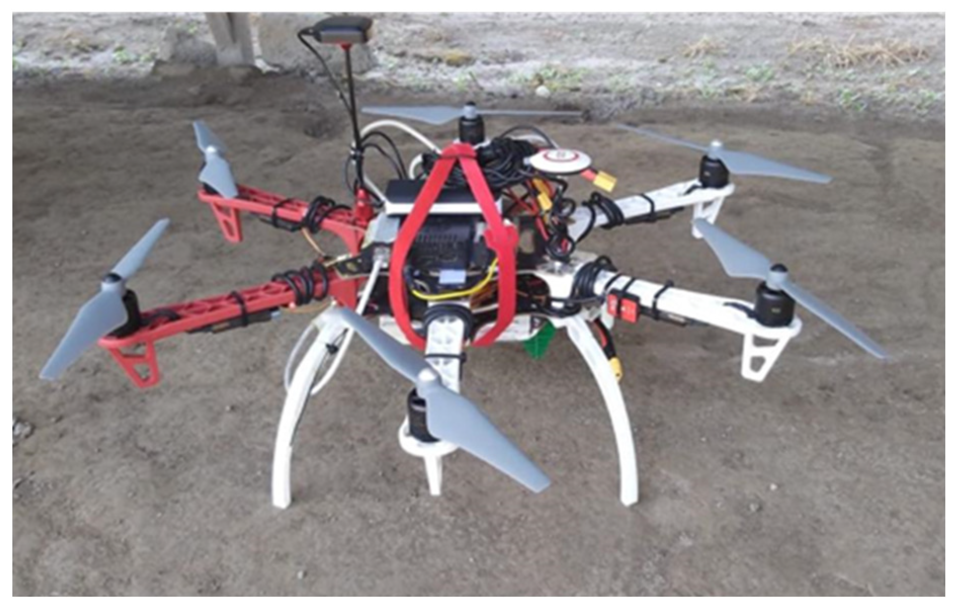
| System 8 [11] | Pulsed Pulson P440 | Frequency bandwidth: 3.1–4.8 GHz Carrier frequency: 3.95 GHz | Two log-periodic PCB antennas (Ramsey LPY26) | Quasi-monostatic configuration: down-looking | Self-assembled DJI F550 hexacopter |
| System 9 [15] | FMCW | 0.5–3 GHz | Vivaldi patch antennas | Bistatic (quasi-monostatic) | DJI Matrice 600 Pro |
| System 10 [16] | SFCW Planar R60 VNA | Selected frequency step: 10 MHz Selected frequency bandwidth: 500–700 MHz | Hybrid horn-dipole antenna transmitting and receiving, combining a tapered TEM horn and a half-wave dipole | Monostatic stepped-frequency continuous wave (SFCW) | X8 model made of 8 motors and 4 arms (2 motors per arm) from RCTakeOff |
| System 11 [17] | SFCW | 0.55–2.7 GHz | Hybrid Vivaldi-Horn antenna | Bistatic (quasi-monostatic) | DJI Matrice 600 Pro |
| System 12 [18] | Pulsed Cobra Plug-In GPR | 0.5–260 MHz | COBRA Plug-in SE-150 | Monostatic | DJI Matrice 600 Pro |
| System 13 [19] | Pulsed Cobra Plug-In GPR Cobra CBD Zond-12e | 0.5–1000 MHz | COBRA Plug-in SE-70 COBRA Plug-in SE-150 Cobra CBD 200/400/800 | Monostatic | DJI Matrice 600 DJI Matrice 600 Pro |
| System 14 [23] | Pulsed K2 IDS radar | Carrier frequency: 900 MHz (bandwidth not specified) | Not specified | Monostatic | Venture VFF_H01 |
| Parameters | Specification |
|---|---|
| Carrier frequency | 3950 MHz |
| Frequency band | 3100–4800 MHz |
| Pulse repetition frequency | 14.28 Hz |
| Parameters | Specification |
|---|---|
| Time-gating window | 24–40 ns |
| Frequency range | 3100–4800 MHz |
| Frequency step | 30 MHz |
| Parameters | Specification |
|---|---|
| Carrier frequency | 500 MHz |
| Frequency band | 600 MHz |
| Pulse repetition frequency | 33 Hz |
| Parameters | Specification |
|---|---|
| Zero time | 2 ns |
| Time-gating window | 8–30 ns |
| Background relative permittivity | 16 |
| Frequency range | 200–800 MHz |
| Frequency step | 18.75 MHz |
Publisher’s Note: MDPI stays neutral with regard to jurisdictional claims in published maps and institutional affiliations. |
© 2022 by the authors. Licensee MDPI, Basel, Switzerland. This article is an open access article distributed under the terms and conditions of the Creative Commons Attribution (CC BY) license (https://creativecommons.org/licenses/by/4.0/).
Share and Cite
Noviello, C.; Gennarelli, G.; Esposito, G.; Ludeno, G.; Fasano, G.; Capozzoli, L.; Soldovieri, F.; Catapano, I. An Overview on Down-Looking UAV-Based GPR Systems. Remote Sens. 2022, 14, 3245. https://doi.org/10.3390/rs14143245
Noviello C, Gennarelli G, Esposito G, Ludeno G, Fasano G, Capozzoli L, Soldovieri F, Catapano I. An Overview on Down-Looking UAV-Based GPR Systems. Remote Sensing. 2022; 14(14):3245. https://doi.org/10.3390/rs14143245
Chicago/Turabian StyleNoviello, Carlo, Gianluca Gennarelli, Giuseppe Esposito, Giovanni Ludeno, Giancarmine Fasano, Luigi Capozzoli, Francesco Soldovieri, and Ilaria Catapano. 2022. "An Overview on Down-Looking UAV-Based GPR Systems" Remote Sensing 14, no. 14: 3245. https://doi.org/10.3390/rs14143245
APA StyleNoviello, C., Gennarelli, G., Esposito, G., Ludeno, G., Fasano, G., Capozzoli, L., Soldovieri, F., & Catapano, I. (2022). An Overview on Down-Looking UAV-Based GPR Systems. Remote Sensing, 14(14), 3245. https://doi.org/10.3390/rs14143245