Abstract
Precise point positioning (PPP) technology is one of the core technologies in the field of GNSS high-precision positioning. It is used widely because it can realize centimeter-level positioning in outdoor environments by using only a single receiver. However, its convergence is time-consuming, particularly in urban areas where satellite occlusion is more severe. A combined BeiDou Navigation Satellite System (BDS) and fifth generation mobile communication technology (5G) PPP observation model is proposed, in which the two kinds of observations are combined and solved at the original observation level. The impact of different numbers and geometries of 5G base stations on the convergence time of PPP is analyzed from both static and dynamic perspectives. The results confirm that PPP technology combining BDS and 5G can effectively accelerate convergence while improving the accuracy of positioning.
1. Introduction
Precise point positioning (PPP) technology has broad application prospects owing to its simplicity of operation, all-weather global nature, and high accuracy [1,2]; however, it suffers from limitations that cannot be ignored. First, the high orbital altitude of the navigation satellite constellation weakens the transmitted navigation signals during propagation, and PPP cannot provide continuous and reliable navigation and positioning services in signal-obscured areas such as indoors, forests, and urban canyons [3,4]. Second, the geometric position of navigation satellites changes very slowly with respect to ground stations, and long convergence times do not satisfy certain fast and precise positioning requirements [5].
Fifth generation mobile communication technology (5G) provides new opportunities for the navigation and positioning business. Compared with fourth generation mobile communication technology, 5G has a larger bandwidth and higher frequency, which enables a more mature positioning performance [6]. In particular, the deployment of 5G base stations will also optimize the geometric configuration of navigation satellites and shorten the convergence time of PPP. In addition, compared with Bluetooth, Wi-Fi, and ultra-wideband (UWB), 5G is based on existing communication base stations and does not require additional base stations [7,8], so it has a lower cost. Compared with inertial navigation system (INS), pedestrian dead reckoning (PDR) and other means, 5G positioning can avoid error accumulation [9,10].
Shahmansoori et al. derived the Cramér-Rao bound (CRB) for estimating position and rotation angle from 5G millimeter wave signals of a single transmitter in the presence of scatterers [11]. Through simulation experiments, Liu et al. found that the quality of 5G positioning results was mainly affected by two factors, namely, poor geometric distribution quality of 5G base stations and multipath propagation of 5G millimeter wave signals [12]. Wang et al. proposed a method for suppressing multipath effects on urban canyons, tunnels and indoors, which is called Two-Stage Multipath Estimating Delay Lock Loop (TS-MEDLL) [13]. Experimental results show that the proposed new method is effective in reducing the positioning errors caused by multipath effects and outperforms existing methods in positioning based on 5G. Based on the measured data from indoor environments, Li et al. compared three different 5G TDOA positioning algorithms. It was learned through experiments that the indoor positioning accuracy could reach 0.289 m statically and 0.608 m dynamically [14]. Papp et al. created a channel model and simulation framework based on 5G measurements in an open-office building and used the framework to study the positioning performance of several algorithms [15].
Positioning algorithms research on fused global navigation satellite systems (GNSS) and 5G technology is currently in its infancy. For example, Rosado et al. combined GNSS and 5G observations at the physical level and evaluated their positioning capabilities in an urban macrocellular environment [16]. They also combined this with a three-dimensional (3D) city map, using the vector information of buildings and receivers in the 3D city map to calculate the visibility of satellites, and eliminate low-quality satellite observations [17,18]. The Fisher information matrix for the positioning system combined with GNSS and 5G was derived, and lower bounds for the errors of position, rotation and clock were calculated by Destino et al. [19]. Yin et al. developed a GNSS-5G positioning method based on inter-device communication and angular measurements, and demonstrated that it could improve positioning accuracy [20]. Roman et al. processed GNSS and 5G data with machine learning methods to achieve seamless integration [21]. Bai et al. proposed a solution method for hybrid GNSS and 5G positioning, called multiple-rate adaptive Kalman filter (MRAKF), and real-world driving experiments showed that the proposed new method improved positioning accuracy significantly, compared to traditional methods [22]. Li et al. proposed a model that combined BDS pseudorange with 5G raw observations and studied the influence of the layout of base stations on the positioning effect [23]. Despite the significant contributions of these studies, they are all based on the standard single point positioning (SPP) approach, and no research has been carried out on a combined BDS–5G PPP model.
Therefore, in this study, a combined BDS and 5G PPP model is developed by introducing carrier phase observations of BDS and 5G time of arrival (TOA) observations. The impact of different numbers and geometries of 5G base stations on the convergence effect of PPP is analyzed from both static and dynamic perspectives under different numbers of visible satellites.
2. Methodology
2.1. Observation Model for BDS–5G PPP
2.1.1. Observation Model for BDS PPP
The BDS PPP observation model is shown in Equations (1) to (2):
where is the subscript of frequency ; superscript is the satellite number; is the pseudorange observation; is the carrier phase observation; is the geometric distance from the receiver to the satellite; represents the receiver’s clock difference; is the satellite clock difference; is the speed of light; is the wavelength; is the ambiguity; , , and represent ionospheric delay, tropospheric delay, tidal and relativistic effects, respectively; and represent other measurement noise.
2.1.2. Observation Model for 5G Millimeter Wave
The 5G millimeter wave positioning uses a time of arrival observation model that takes into account the receiver-base station clock difference, as shown in Equation (3):
where is the base station number; is the 5G millimeter wave observation; is the speed of light; is the geometric distance between the receiver and the base station; is the 5G receiver’s clock difference; represents other measurement noise.
2.1.3. Observation Model for BDS–5G PPP
BDS PPP uses the ionosphere-free combination, and then, the BDS PPP observation model and 5G millimeter wave observation model are normalized to a unified coordinate system. Equations (1)–(3) are coupled to obtain the combined BDS–5G observation model as shown in Equation (4):
where and are the pseudorange and carrier phase of dual-frequency ionosphere-free combination observations, respectively; ; ; and are the residuals of iono-free combination.
2.2. Weight Matrix
The weight strategy is shown in Equation (5). The satellite observation adopts an elevation angle weighting strategy, that is, the weight of satellite carrier phase observation with an altitude angle greater than 30° is set to 1, and the satellites with an altitude angle less than 7° are deleted. The pseudorange weight is set to 1/10,000 of the carrier phase observation weight according to experience. Considering the ranging accuracy of 5G TOA, we set the weight of 5G observation value to 1/100 of the carrier phase weight, as shown in Equations (6)–(8).
where represents the weight; represents the elevation angle of satellite; represents the variance of unit weight; represents the variance of the observations; the other symbols have the same meaning as before.
2.3. Data Processing Strategy
As shown in Table 1.

Table 1.
Data processing strategies.
3. Results and Discussion
3.1. Experimental Environment
3.1.1. BDS Test Environment
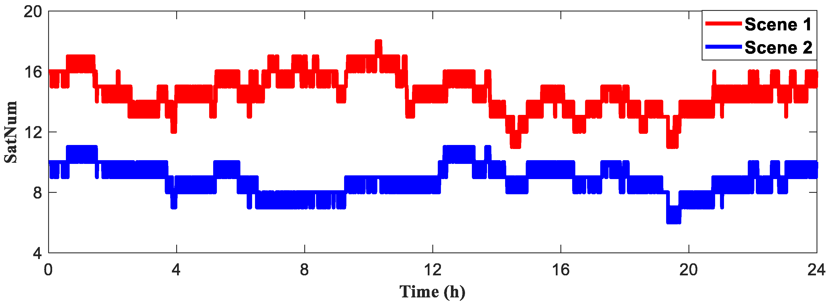
The experiment used observation files from the JFNG station downloaded from the MGEX website for day 225 of 2021, using BDS data with a sampling interval of 30 s and a data length of 24 h. Two scenes are shown in Figure 1 with different numbers of BDS satellites involved in positioning, red for Scene 1 and blue for Scene 2. The number of visible satellites is greater in Scene 1 than in Scene 2.
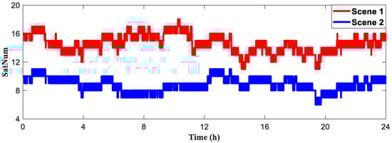
Figure 1.
Number of satellites for BeiDou Navigation Satellite System (BDS) involved in the solutions for Scene 1 and Scene 2.
3.1.2. 5G Environment
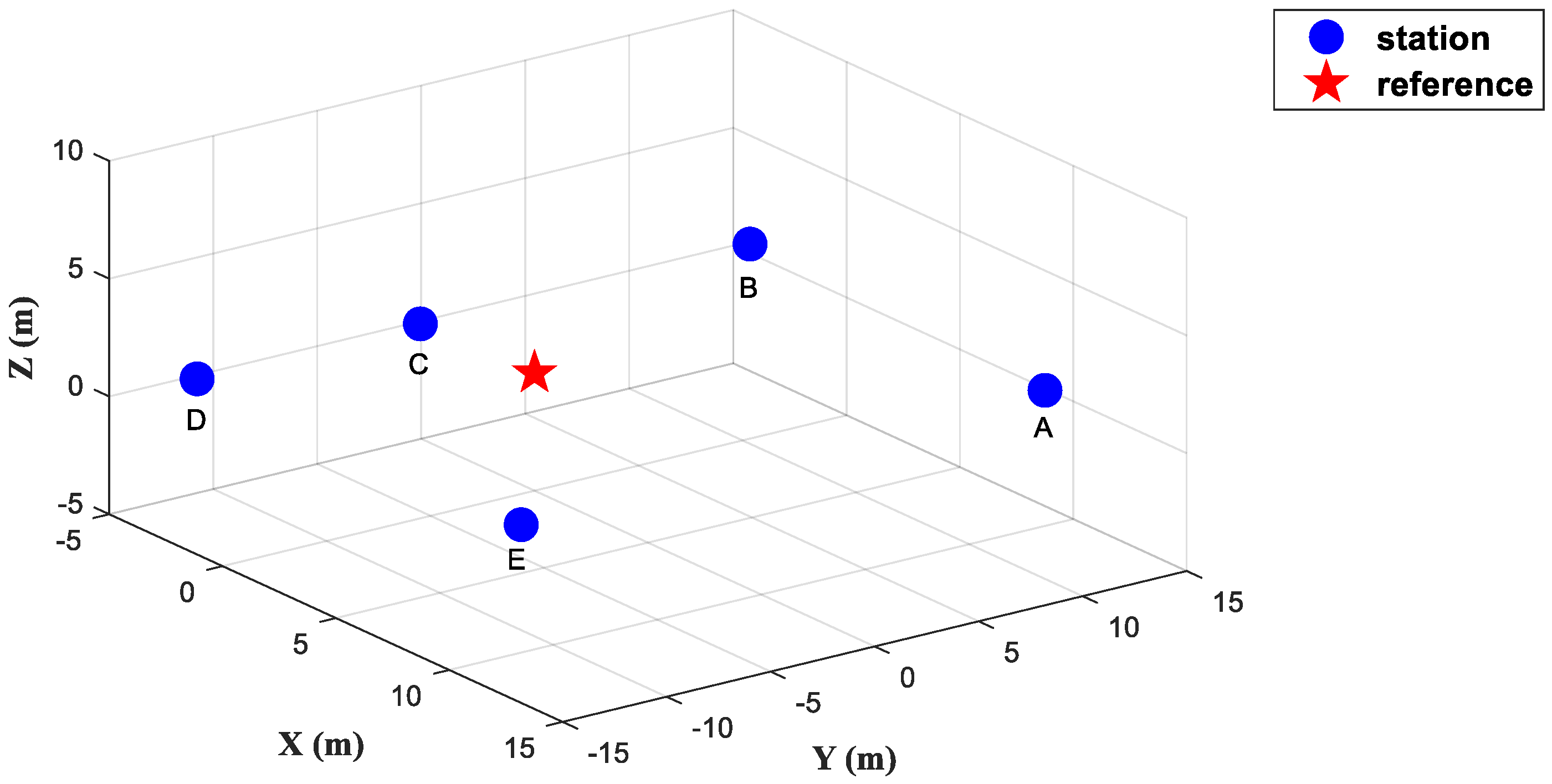
As shown in Figure 2, five 5G micro base stations were deployed at the National Time Service Center of the Chinese Academy of Sciences in Xi’an, China. The experimental field was a rectangular area of 30 m × 50 m. The frequency of the 5G signal used in the experiment was 3.5 GHz, the bandwidth of the signal was 100 MHz, and the accuracy of time synchronization was greater than 1 ns. Under the local coordinate system, the coordinates of the point to be measured were set to (0, 0, 0) m and the total number of base stations was five. The coordinates of the 5G micro base stations were as follows: base station A (11.851, 11.621, 2.005) m, base station B (−1.688, 12.198, 2.122) m, base station C (−1.419, −3.943, 2.299) m, base station D (−1.379, −14.719, 2.283) m, and base station E (12.765, −14.554, 2.292) m.

Figure 2.
Different numbers of fifth generation mobile communication technology (5G) base stations.
In our previous experiments, we tested the positioning performance of 5G base stations in the above environment, in which we compared the positioning accuracy of the measured data and simulated data and investigated the advantages of combined SPP and 5G positioning in the occluded environment. The details of the experiments were described in paper [23].
In order to perform a combined BDS and 5G positioning test, we panned this set of actual 5G TOA data and base stations so that the point to be measured overlapped with the JFNG station and performed the following experiments on the effect of the quantity of 5G micro base stations on the PPP results.
With each successive experiment, the quantity of base stations was increased from one to five in the order of ABCDE. In Scene 1, as the quantity of 5G base stations increased, the position dilution of precision (PDOP) values decreased, with a 11.29% decrease for the case with five base stations compared with the case without base stations (Table 2). In Scene 2, the contribution of 5G base stations to the PDOP value was more obvious; compared with the PDOP value without base stations, the PDOP value of the five base stations decreased by 17.55%.
Table 2.
Position dilution of precision (PDOP) for different numbers of fifth generation mobile communication technology (5G) base stations in two scenes.
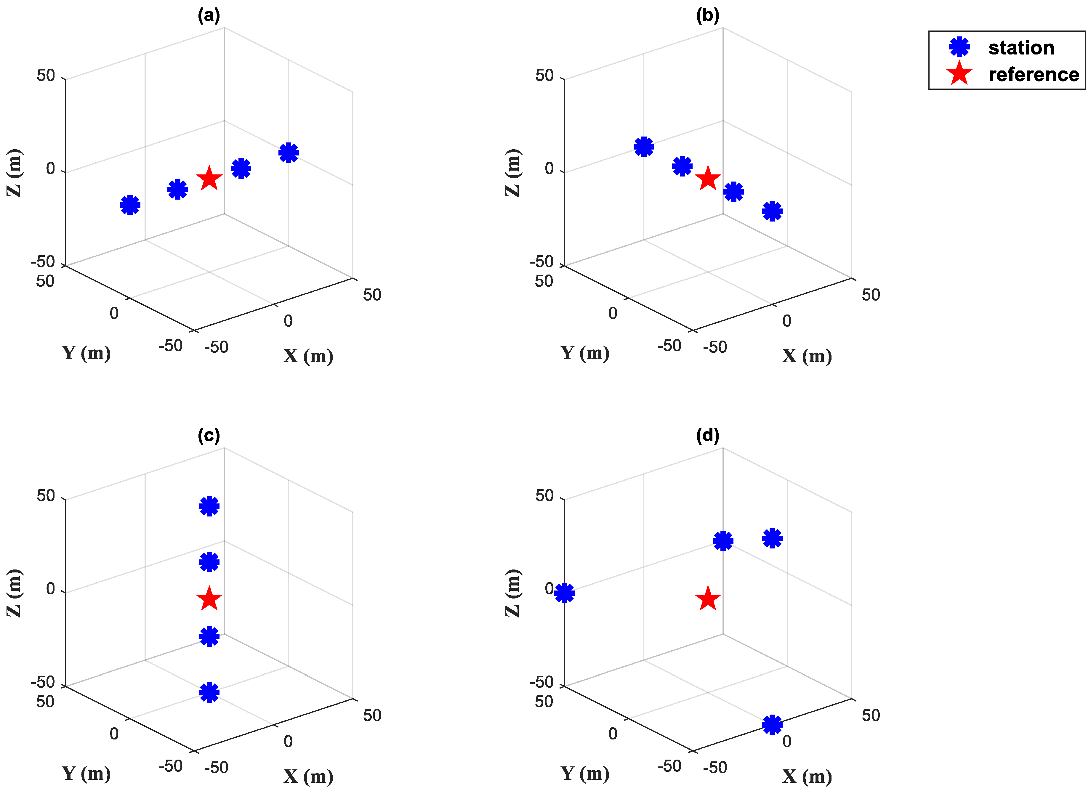
In addition, in order to simulate the effect of different geometrical configurations of base station deployment on PPP, we simulated four sets of base station combinations with different geometrical configurations (Figure 3): Groups A, B, C, and D.
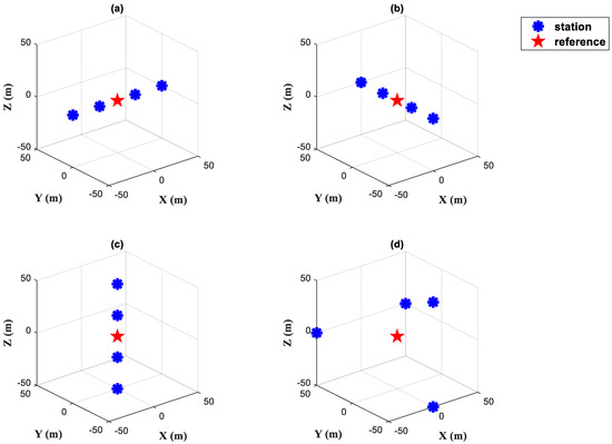
Figure 3.
Fifth generation mobile communication technology (5G) base stations with different geometrical configurations, (a): Group A, (b): Group B, (c): Group C, (d): Group D.
The simulated data consists of three components, namely, the real distance, receiver clock difference and measurement noise, where the receiver clock difference and measurement noise are obtained from the difference between the measured data and the real distance as described above, as shown in Equation (9).
where represents the simulated TOA; represents the real distance between the receiver and the analogue base station; represents the difference between the measured data and the true distance in Figure 2.
In all four combinations, the number of base stations was four. The coordinates of the base stations in the local coordinate system are shown in Table 3. Analysis of the dilution of precision (DOP) values in each direction (Table 4) shows that Group A had the greatest configuration advantage in the X direction, Group B had the greatest advantage in the Y direction, and Group C had the greatest advantage in the Z direction. Group D was relatively balanced, and this conformational advantage was more pronounced when the number of satellites was small.
Table 3.
Coordinates of fifth generation mobile communication technology (5G) base stations with different geometrical configurations (unit: m).
Table 4.
Dilution of precision (DOP) values for different geometric configurations of fifth generation mobile communication technology (5G) base stations in two scenes.
3.2. Static PPP
3.2.1. Quantity
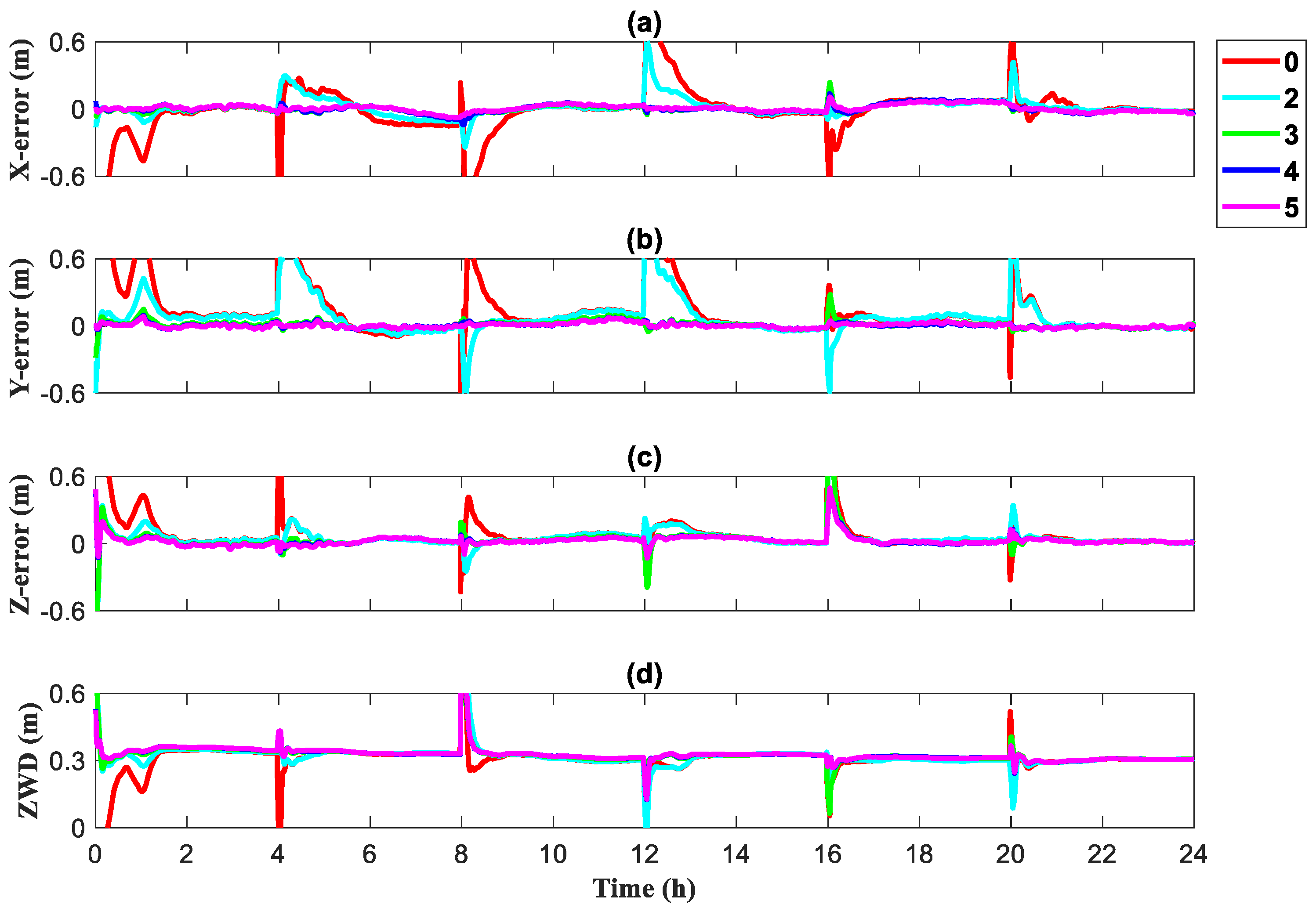
The 24 h of BDS satellite observations were initialized every 4 h to obtain the convergence effect plots of static PPP in XYZ directions and tropospheric zenith wet delay under Scenes 1 and 2.
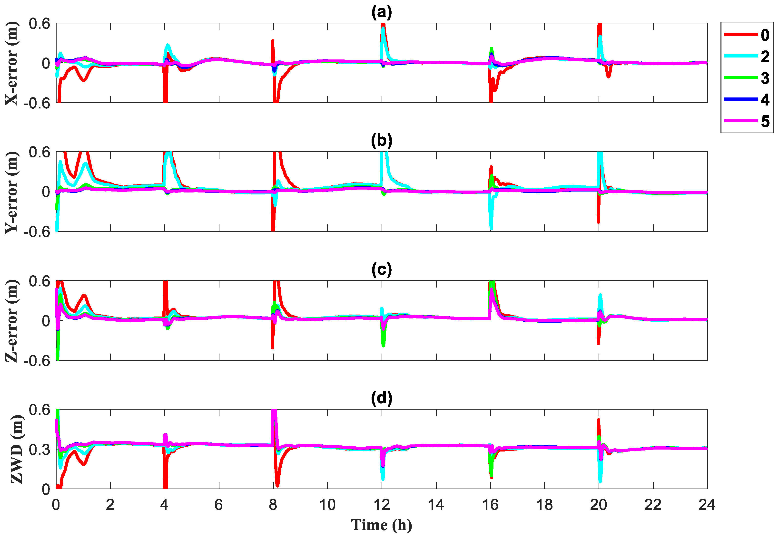
The static PPP convergence effect for Scene 1 is shown in Figure 4, with different numbers of 5G base stations involved in localization. In the case of no base station participation, represented in red, the convergence speed of its XYZ directions and tropospheric zenith wet delay is significantly slower than that of the case with 5G base stations participating in positioning. As the quantity of participating 5G base stations increases, the static PPP converges faster. The results of Scene 2 are shown in Figure 5; the same conclusions can be drawn and the beneficial effect of the 5G base station involvement in positioning is further enhanced owing to the reduced number of visible satellites.
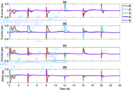
Figure 4.
Convergence for different numbers of base stations in Scene 1, (a) X direction, (b) Y direction, (c) Z direction, (d) Zenith wet delay.
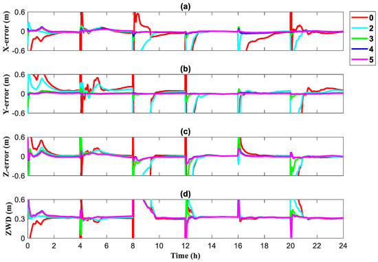
Figure 5.
Convergence for different numbers of base stations in Scene 2, (a) X direction, (b) Y direction, (c) Z direction, (d) Zenith wet delay.
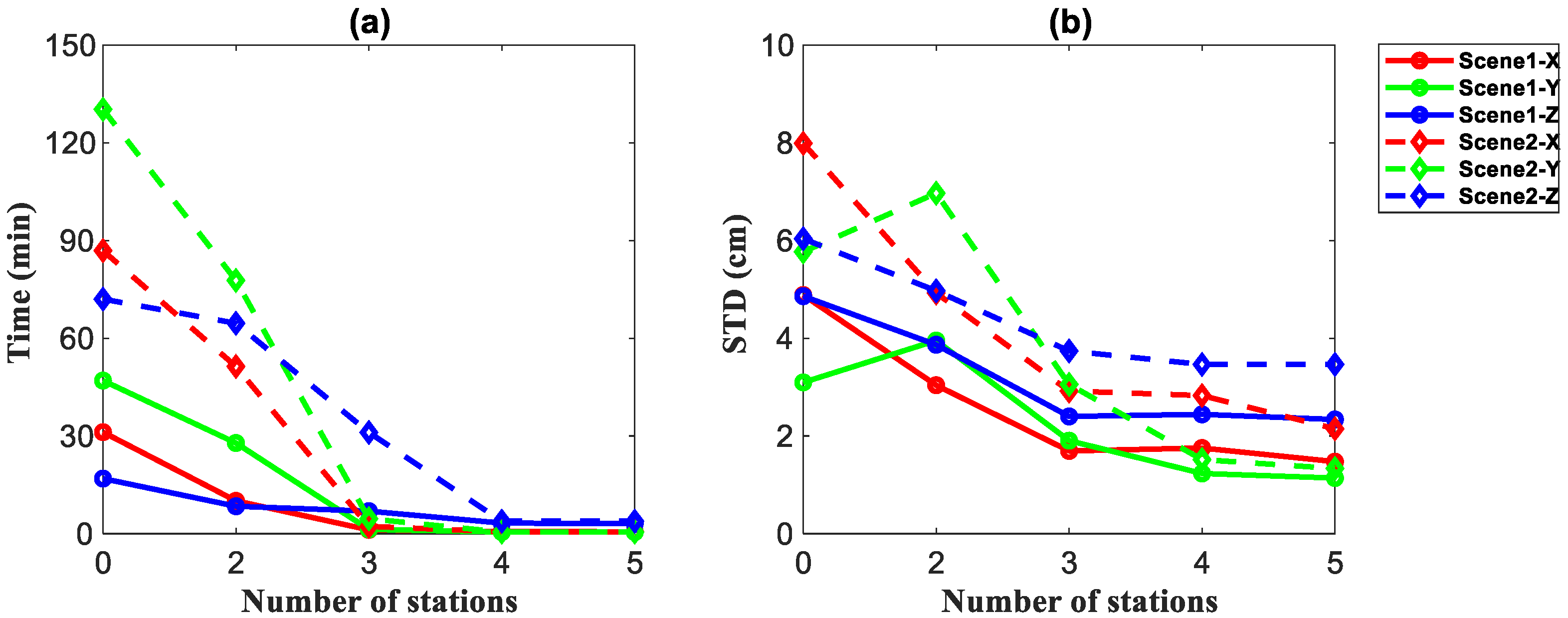
To more clearly illustrate the effect of base station number on the effectiveness of PPP in different occlusion scenes, the mean convergence time and STD variation of the error for six initializations in a day were counted. In the static solution process, we considered an error of less than 0.1 m for 30 consecutive epochs as convergence.
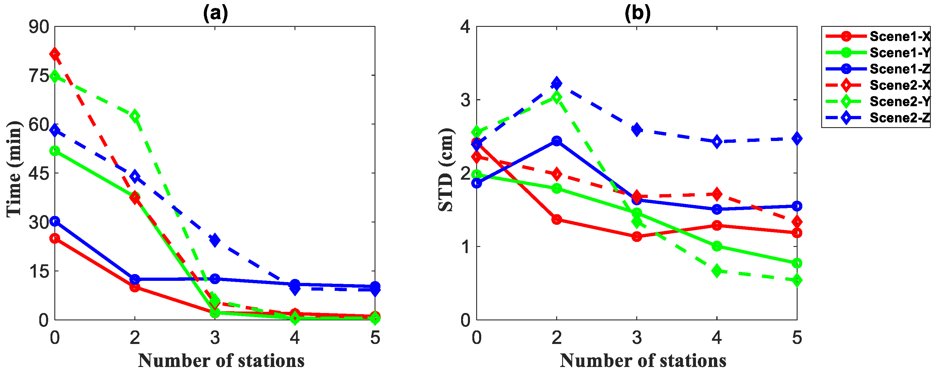
From the mean results after six initializations in different scenes (Figure 6), in the static PPP mode, the convergence time showed a decreasing trend in all three XYZ directions as the number of base stations increased. In Scene 1, the convergence speed accelerated by 23 min, 51 min, and 19 min in the XYZ directions for the three base stations involved in localization compared to no base station. When the quantity of 5G base stations was increased to three and then to four and five, the trend of decreasing convergence time diminished and then plateaued. As the quantity of base stations involved in the positioning solution increased, the STD of the post-convergence error decreased slightly, and the STD of five-base station positioning was 1.187 m, 0.7873 m, and 1.551 m in the XYZ directions.
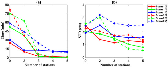
Figure 6.
Convergence speed (a) and standard deviation (STD) (b) of the errors for different numbers of base stations under Scene 1 and Scene 2.
The convergence speed in Scene 2 improved more rapidly than in Scene 1 as the quantity of base stations increased, and the convergence speed accelerated by 76 min, 69 min, and 33 min in the XYZ directions for the three-base station case compared with the no base station case, which is a greater reduction than that in Scene 1. At the same time, compared with Scene 1 where the convergence advantage became less pronounced for more than three base stations, when the quantity of base stations increased to four and five, the convergence speed in Scene 2 still had some advantages. With four to five base stations involved in the solution, the convergence times for Scene 1 and Scene 2 converged to within 15 min. The change in the STD of the error after convergence was less pronounced, but there was also a general tendency to decrease, from over 2.0 m to under 1.5 m in both the XY directions.
Therefore, we conclude that 5G base stations participating in static PPP can effectively reduce the convergence time and increase the positioning accuracy to a certain extent. The more 5G base stations, the better the positioning effect. This advantage is more obvious in an environment where satellites are blocked.
3.2.2. Geometric Configuration
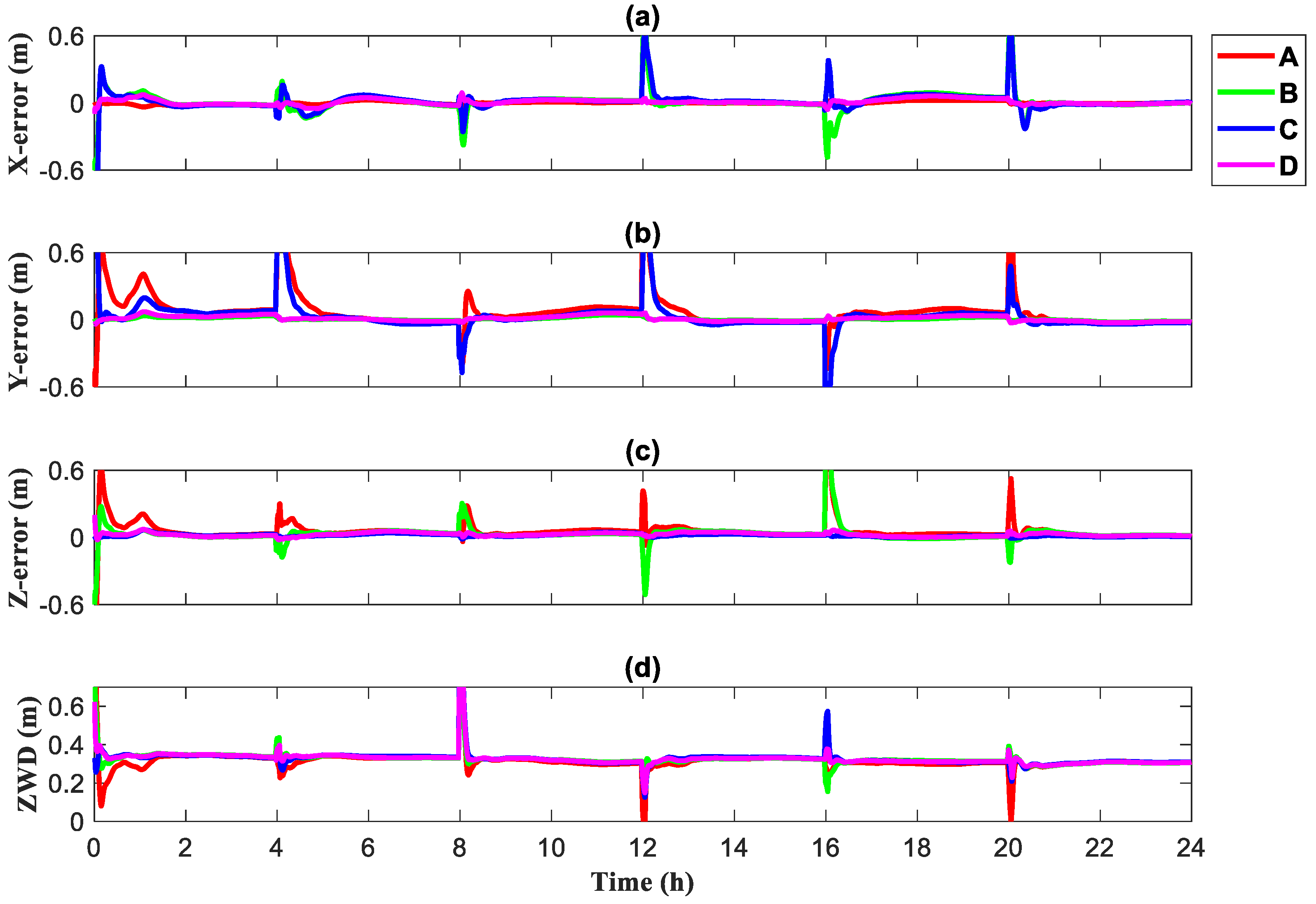
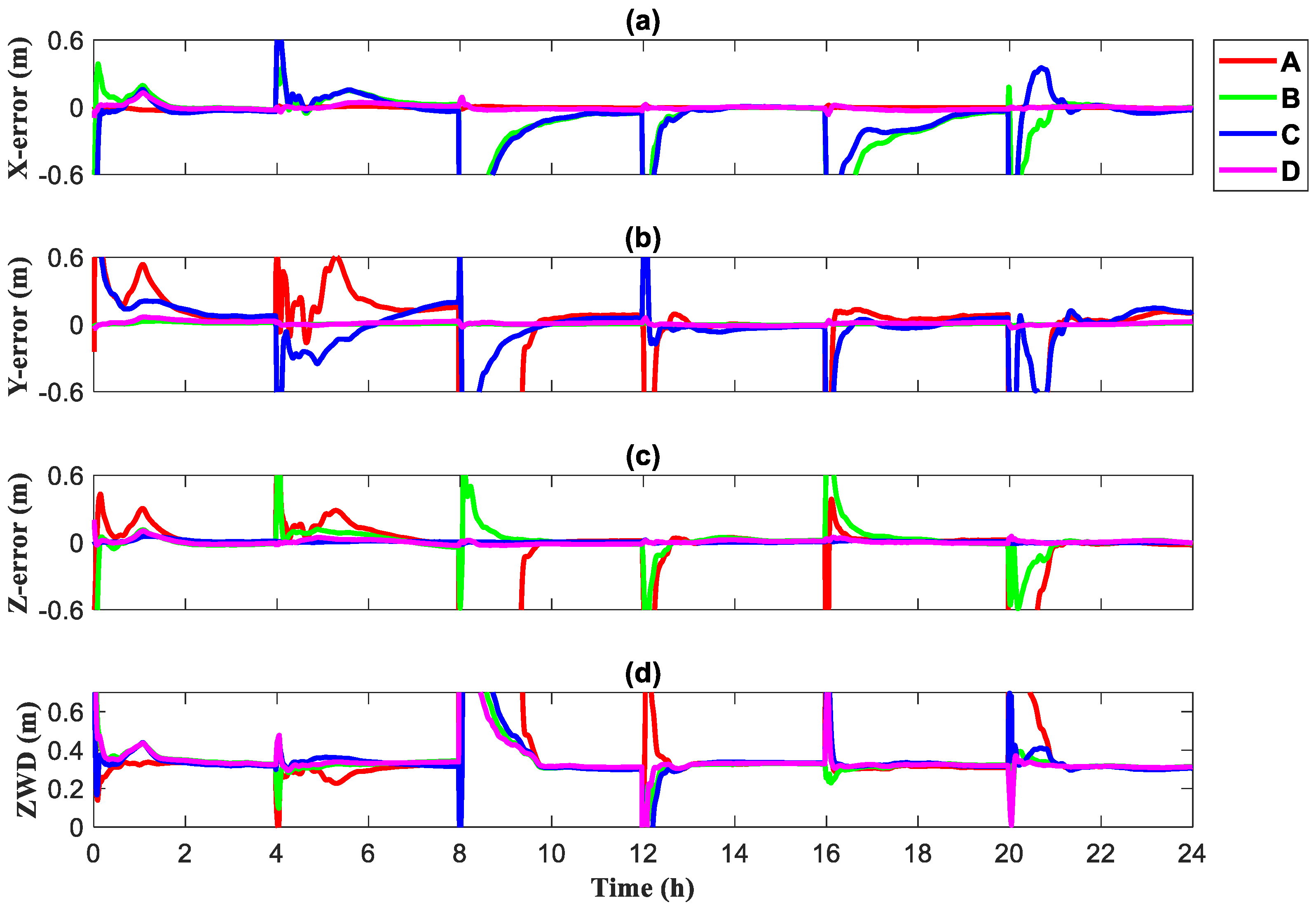
Figure 7 and Figure 8 show the convergence results for static PPP and tropospheric zenith wet delay in the XYZ directions for Scenes 1 and 2, respectively, with different colors representing the different geometric configurations involved in the PPP. Figure 9 shows how the mean convergence time and STD of the error varied over the six initializations per day.
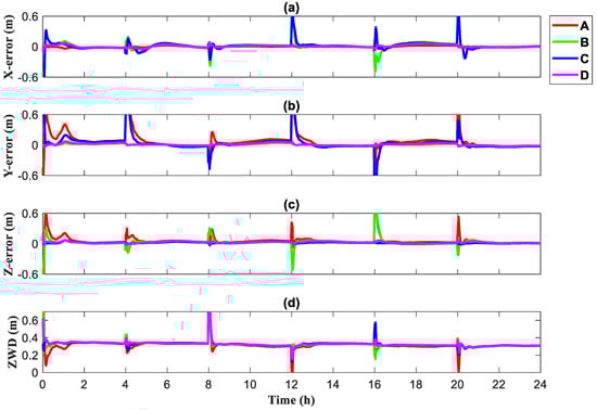
Figure 7.
Convergence of different base station geometries for Scene 1, (a) X direction, (b) Y direction, (c) Z direction, (d) Zenith wet delay.
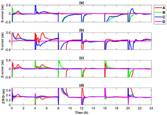
Figure 8.
Convergence of different base station geometries for Scene 2, (a) X direction, (b) Y direction, (c) Z direction, (d) Zenith wet delay.
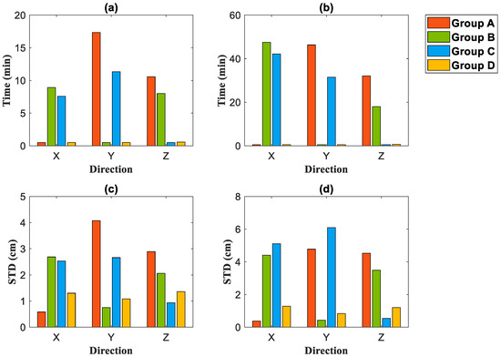
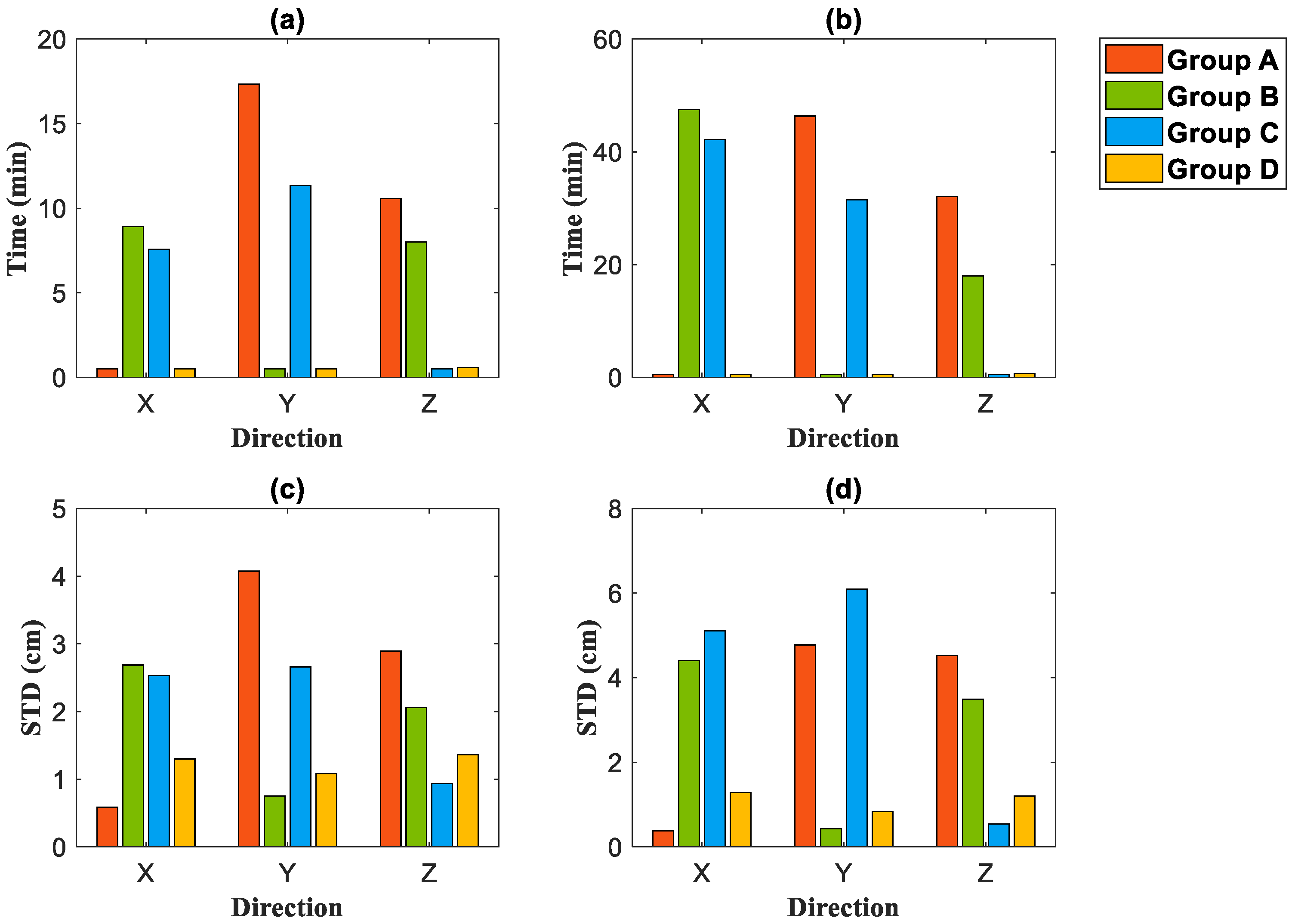
Figure 9.
Convergence speed and standard deviation (STD) of the errors for different base station geometry configurations under Scene 1 and Scene 2, (a) Convergence speed under Scene 1, (b) Convergence speed under Scene 2, (c) STD under Scene 1, (d) STD under Scene 2.
In Scene 1, the dominant configurations were able to converge in 2 min in their corresponding directions. The advantages for the error standard deviation after convergence in the dominant direction were clear. The STD of the error was significantly reduced, with the STD of Group A in the X direction being 55.14% less than that of Group D, the STD of Group B in the Y direction was 30.46% less than that of Group D, and the STD of Group C in the Z direction was 31.45% less than that of Group D. TheSTD in each dominant direction was less than 1 cm.
Compared with Scene 1, the geometric configuration in Scene 2 had more significant advantages. In terms of convergence time, Groups A, B, C and Group D were able to converge in a few minutes in their respective dominant directions. In terms of the change in the STD of errors, the STD of Group A in the X direction was reduced by 70.48% compared with that of Group D, the STD of Group B in the Y direction was reduced by 48.76% compared with that of Group D, and the STD of Group C in the Z direction was reduced by 66.17% compared with that of Group D, and the reduction in the STD of the errors was greater than that of Scene 1. When the dominant configuration was involved in each direction, the convergence speed and accuracy of Scene 2, which had a smaller number of satellites, almost reached the same level as Scene 1.
From this, we can see that the geometric configuration of 5G base stations has a great impact on the convergence of PPP in combined positioning. We can obtain very short convergence times and high-precision location information by deploying the advantageous base station configuration in the direction of the target.
3.3. Dynamic PPP
3.3.1. Quantity
We performed a static imitation dynamic model solution based on the same experimental setting and data described in Section 3.2. In the dynamic solution process, we considered an STD error of less than 0.3 m for 30 consecutive epochs as convergence.
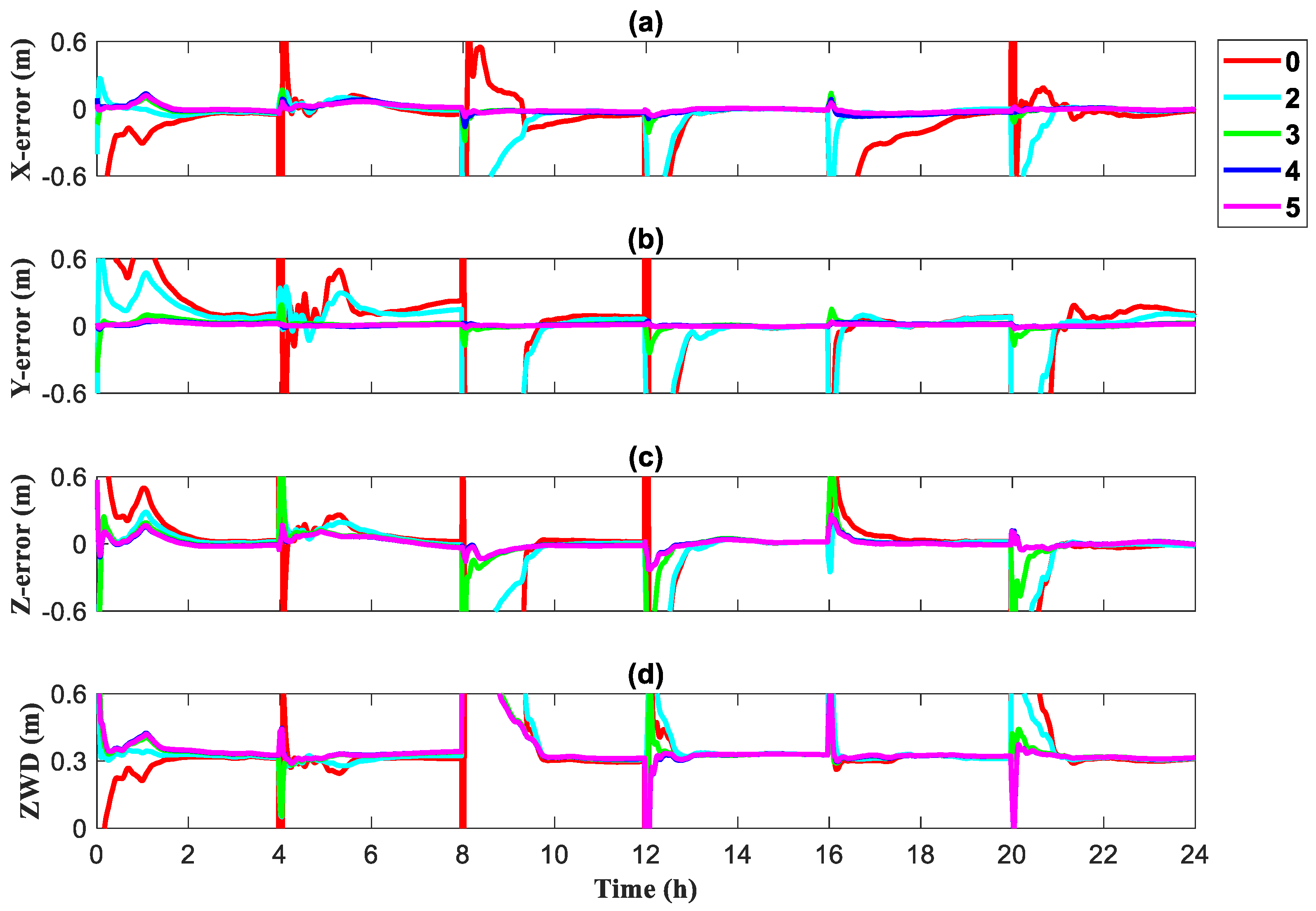
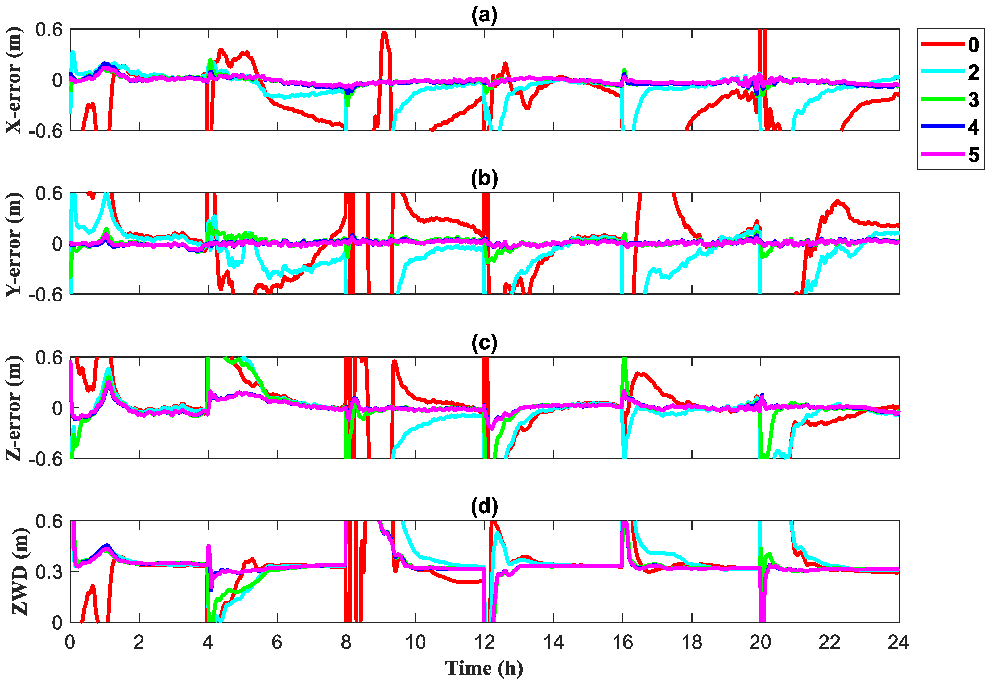
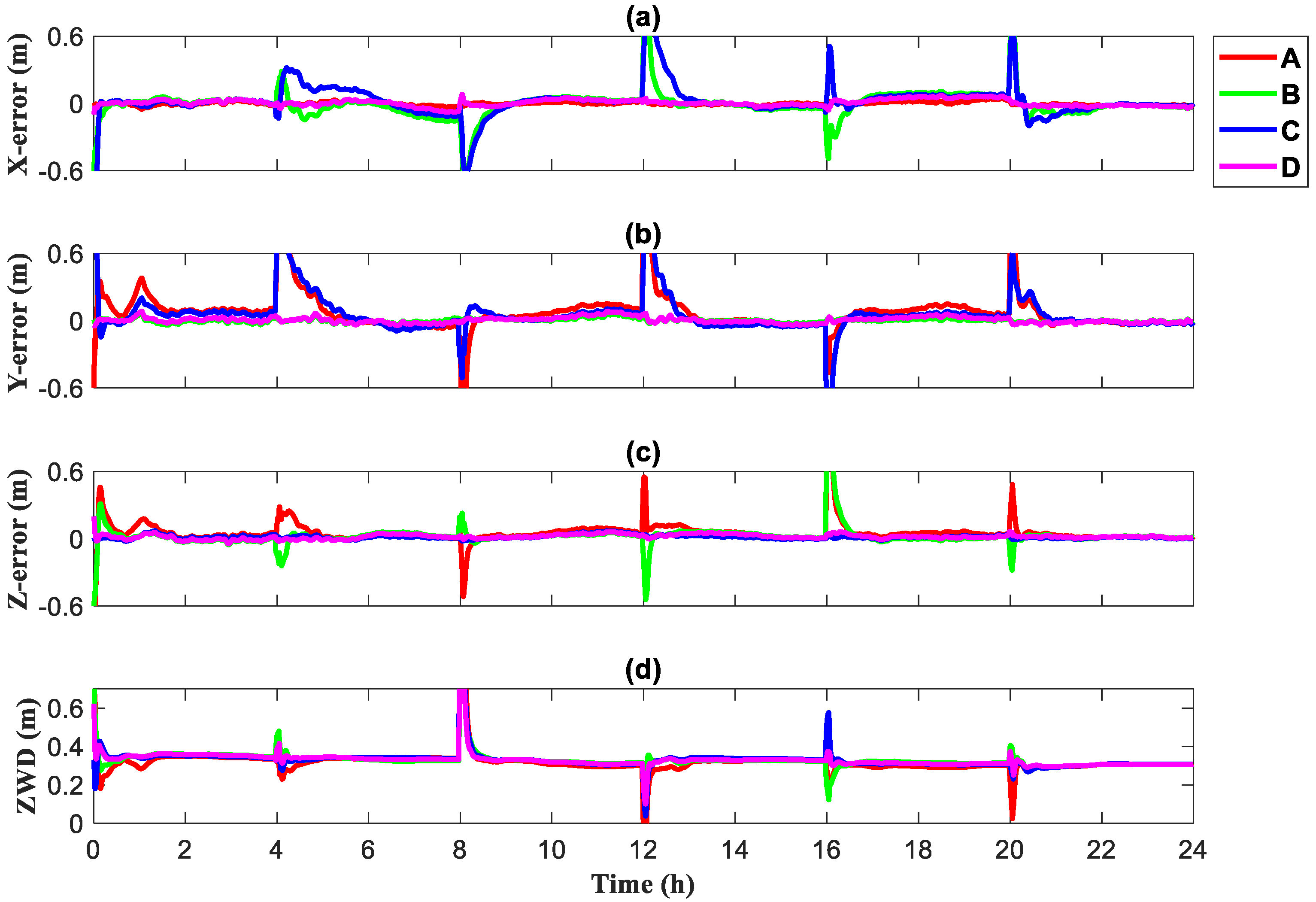
Figure 10 and Figure 11 show the results of dynamic PPP for different numbers of 5G base stations involved in localization in Scenes 1 and 2 (from top to bottom, the convergence of XYZ directions and tropospheric zenith wet delay). During the convergence of the dynamic PPP, the convergence rate of each direction and the tropospheric zenith wet delay tended to accelerate as the quantity of base stations increased.
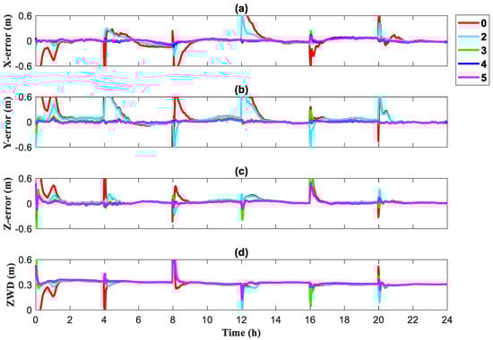
Figure 10.
Convergence for different numbers of base stations in Scene 1 (dynamic precise point positioning [PPP]), (a) X direction, (b) Y direction, (c) Z direction, (d) Zenith wet delay.
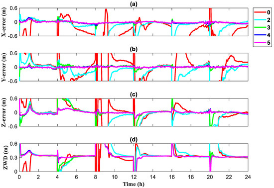
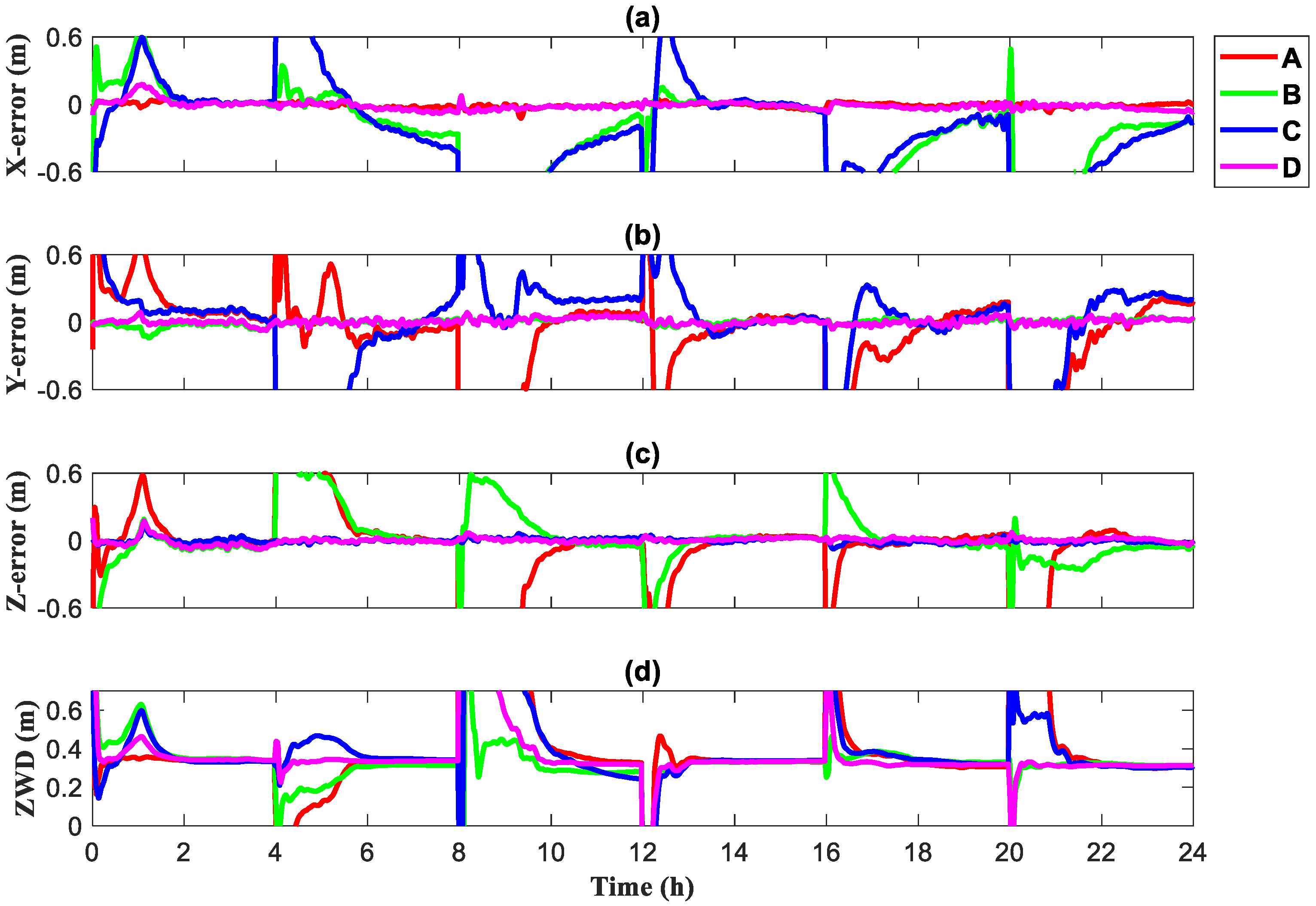
Figure 11.
Convergence for different numbers of base stations in Scene 2 (dynamic precise point positioning [PPP]), (a) X direction, (b) Y direction, (c) Z direction, (d) Zenith wet delay.
The mean convergence time and STD of the error variation for the six initializations in a day are presented in Figure 12. The convergence times for both scenes in the dynamic PPP solution mode showed an overall decreasing trend as the number of base stations increased. In Scene 1, when three base stations were introduced, the convergence time reduced to less than 10 min in all directions. The convergence time decreased by 50.01%, 62.50%, and 55.42% in the XYZ directions, respectively, when five base stations were introduced compared with three base stations. In Scene 2, when three base stations were introduced, the convergence times in the XY directions were reduced to less than 10 min. However, although the convergence speed in the Z direction was 50% faster than that in the case of no base station, it still took 30 min to converge, and we consider that this was due to the poor distribution of 5G base stations in the Z direction. When five base stations were introduced, they were able to converge in all directions within 5 min.
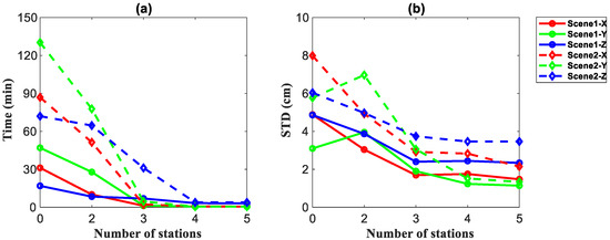
Figure 12.
Convergence speed (a) and standard deviation (STD) (b) of the errors for different numbers of base stations under Scene 1 and Scene 2 (dynamic precise point positioning [PPP]).
The STD of the errors also decreased after convergence. In Scene 1, the STD of the errors decreased by 69.82%, 63.23%, and 51.91% in the XYZ directions, respectively, when five base stations were introduced compared with no base stations. In Scene 2, compared with no base stations, the STD of the errors decreased by 73.13%, 76.88%, and 42.60% in the XYZ directions, respectively, when five base stations were involved in the positioning.
From this, we can see that in dynamic PPP, the introduction of 5G observations can speed up the convergence time and contribute to the reduction of error STD after convergence. When there are few available satellites, 5G observations can be used as a supplement to obtain better results.
3.3.2. Geometric Configuration
Figure 13 and Figure 14 show the results obtained for 5G base stations with different geometrical configurations participating in the dynamic PPP under Scenes 1 and 2 (from top to bottom, for XYZ directions and tropospheric zenith wet delay). Figure 15 shows the statistics of the mean convergence time and the STD of the errors for the six initializations in a day.
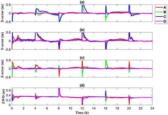
Figure 13.
Convergence of different base station geometries for Scene 1 (dynamic precise point positioning [PPP]), (a) X direction, (b) Y direction, (c) Z direction, (d) Zenith wet delay.
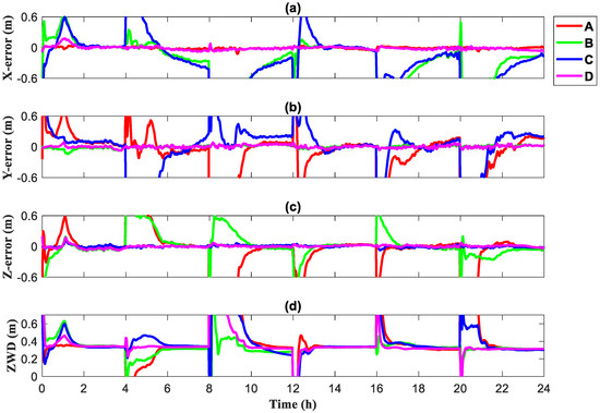
Figure 14.
Convergence of different base station geometries for Scene 2 (dynamic precise point positioning [PPP]), (a) X direction, (b) Y direction, (c) Z direction, (d) Zenith wet delay.

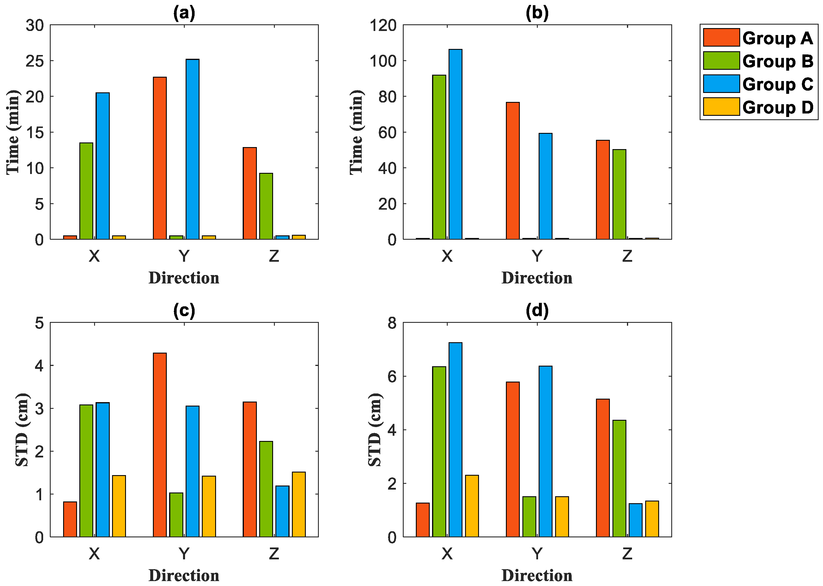
Figure 15.
Convergence speed and standard deviation (STD) of the errors for different base station geometry configurations under Scene 1 and Scene 2 (dynamic precise point positioning [PPP]), (a) Convergence speed under Scene 1, (b) Convergence speed under Scene 2, (c) STD under Scene 1, (d) STD under Scene 2.
As shown in Figure 13 and Figure 14, the various configurations had significant advantages in terms of the convergence speed in their dominant directions, and convergence was achieved in a short time. Again, in Figure 15, there was a significant improvement in the STD of the errors after convergence. Scenes 1 and 2 showed that the error STD of various configurations in their corresponding dominant directions was reduced to within 2 cm.
From this, we can conclude that in the case of dynamic PPP, the introduction of 5G dominant geometry can also achieve very fast convergence in the dominant direction and obtain a low-error STD. Especially in the case of a small number of satellites, dynamic PPP is difficult to converge at times, or there is a large error after convergence. At such times, the introduction of 5G observations can accelerate the convergence and correct the positioning error.
4. Conclusions
A combined BDS and 5G PPP model was proposed, and the effects of different numbers and different geometrical configurations of 5G base stations participating in PPP on the convergence speed of three directions (XYZ) and the tropospheric zenith wet delay from both static and dynamic perspectives were investigated. From the experiments, it can be seen that:
- As the quantity of 5G base stations participating in the positioning solution increases, the convergence time and the STD of the errors after convergence both tend to decrease. The beneficial effect brought about by the participation of 5G base stations in positioning is also evident with a smaller number of visible satellites. In particular, when a single BDS system cannot converge within 1 h or when there is a large post-convergence error in some cases, the involvement of 5G base stations can significantly speed up convergence and achieve better post-convergence positioning accuracy.
- In experiments with different geometrical configurations, there is a significant advantage for speed of convergence and STD of the errors after convergence of the various configurations in their dominant directions compared with the relatively balanced configurations. The advantage is also evident when the number of satellites is low. The dominant geometric configuration in each direction is suitable where rapid convergence is required in a particular target direction.
- The research on BDS and 5G combined precise point positioning technology is conducive to the rapid realization of indoor and outdoor seamless positioning and is of great significance to the development of the PNT community.
Author Contributions
F.L. and R.T. provided the initial idea for this work and wrote this manuscript; F.L. designed the algorithm. F.L., R.T., J.H. and S.Z. contributed to the analyses of results. M.L. and X.L. contributed to the collection and analysis of field test data. F.L. and R.T. drew the pictures. All authors have read and agreed to the published version of the manuscript.
Funding
This research was funded by the National Natural Science Foundation of China, grant number 41974032.
Data Availability Statement
The raw/processed data required to reproduce these findings cannot be shared at this time as the data also forms part of an ongoing study.
Acknowledgments
The work was supported by the Chinese Academy of Sciences (CAS) programs of “High Level Talents”. Thanks to Jianfeng Wu and his research team from the National Time Service Center, Chinese Academy of Sciences, for providing the 5G measured data.
Conflicts of Interest
The authors declare no conflict of interest.
References
- Jin, S.; Su, K. PPP models and performances from single- to quad-frequency BDS observations. Satell. Navig. 2020, 1, 16. [Google Scholar] [CrossRef]
- Zhang, X.; Zhang, Y.; Zhu, F. A method of improving ambiguity fixing rate for post-processing kinematic GNSS data. Satell. Navig. 2020, 1, 20. [Google Scholar] [CrossRef]
- Hsu, L.T. Analysis and modeling GPS NLOS effect in highly urbanized area. GPS Solut. 2018, 22, 7. [Google Scholar] [CrossRef] [Green Version]
- Chen, X.; He, D.; Pei, L. BDS B1I multipath channel statistical model comparison between static and dynamic scenes in dense urban canyon environment. Satell. Navig. 2020, 1, 26. [Google Scholar] [CrossRef]
- Du, Y.; Wang, J.; Rizos, C.; El-Mowafy, A. Vulnerabilities and integrity of precise point positioning for intelligent transport systems: Overview and analysis. Satell. Navig. 2021, 2, 3. [Google Scholar] [CrossRef]
- Zhang, P.; Chen, H. A Survey of Positioning Technology for 5G. J. Beijing Univ. Posts Telecommun. 2018, 41, 1–12. [Google Scholar]
- Qi, W.; Zhen, J. Fusion positioning based on WiFi and Bluetooth for the area around the corner of stairs. In Proceedings of the 2021 IEEE 18th International Conference on Mobile Ad Hoc and Smart Systems (MASS), Denver, CO, USA, 4–7 October 2021; pp. 162–163. [Google Scholar] [CrossRef]
- Zhu, Y.; Luo, X.; Guan, S.; Wang, Z. Indoor Positioning Method Based on WiFi/Bluetooth and PDR Fusion Positioning. In Proceedings of the 2021 13th International Conference on Advanced Computational Intelligence (ICACI), Wanzhou, China, 14–16 May 2021; pp. 233–238. [Google Scholar] [CrossRef]
- Dehghanian, V.; Lowe, M. RSS-INS integration for cooperative indoor positioning. In Proceedings of the 2016 International Conference on Indoor Positioning and Indoor Navigation (IPIN), Madrid, Spain, 4–7 October 2016; pp. 1–7. [Google Scholar] [CrossRef]
- Al Mamun, M.A.; Rasit Yuce, M. Map-Aided Fusion of IMU PDR and RSSI Fingerprinting for Improved Indoor Positioning. In Proceedings of the 2021 IEEE Sensors, Virtual, 31 October–3 November 2021; pp. 1–4. [Google Scholar] [CrossRef]
- Shahmansoori, A.; Garcia, G.E.; Destino, G.; Seco-Granados, G.; Wymeersch, H. Position and Orientation Estimation Through Millimeter-Wave MIMO in 5G Systems. IEEE Trans. Wirel. Commun. 2018, 17, 1822–1835. [Google Scholar] [CrossRef] [Green Version]
- Liu, Q.; Liu, R.; Wang, Z.; Zhang, Y. Simulation and Analysis of Device Positioning in 5G Ultra-Dense Network. In Proceedings of the 2019 15th International Wireless Communications; Mobile Computing Conference (IWCMC), Tangier, Morocco, 24–28 June 2019; pp. 1529–1533. [Google Scholar] [CrossRef]
- Wang, Z.; Liu, R.; Zhang, Y.; Liu, Q. A Novel Multipath Mitigation Method for 5G Positioning. In Proceedings of the 2019 15th International Wireless Communications; Mobile Computing Conference (IWCMC), Tangier, Morocco, 24–28 June 2019; pp. 1714–1718. [Google Scholar] [CrossRef]
- Li, F.; Tu, R.; Han, J.; Zhang, Y.; Hong, J. Indoor location algorithm of TDOA based on 5G. Gnss World China 2021, 46, 1–6. [Google Scholar]
- Papp, Z.; Irvine, G.; Smith, R.; Mogyorósi, F.; Revisnyei, P.; Törős, I.; Pašić, A. TDoA based indoor positioning over small cell 5G networks. In Proceedings of the NOMS 2022–2022 IEEE/IFIP Network Operations and Management Symposium, Budapest, Hungary, 25–29 April 2022; pp. 1–6. [Google Scholar] [CrossRef]
- del Peral-Rosado, J.A.; Renaudin, O.; Gentner, C.; Raulefs, R.; Dominguez-Tijero, E.; Fernandez-Cabezas, A.; Blazquez-Luengo, F.; Cueto-Felgueroso, G.; Chassaigne, A.; Bartlett, D.; et al. Physical-Layer Abstraction for Hybrid GNSS and 5G Positioning Evaluations. In Proceedings of the 2019 IEEE 90th Vehicular Technology Conference (VTC2019-Fall), Honolulu, HI, USA, 22–25 September 2019; pp. 1–6. [Google Scholar] [CrossRef]
- Del Peral-Rosado, J.A.; Saloranta, J.; Destino, G.; López-Salcedo, J.A.; Seco-Granados, G. Methodology for Simulating 5G and GNSS High-Accuracy Positioning. Sensors 2018, 18, 3220. [Google Scholar] [CrossRef] [PubMed] [Green Version]
- Jdel Peral-Rosado, A.; Gunnarsson, F.; Dwivedi, S.; Razavi, S.M.; Renaudin, O.; López-Salcedo, J.A.; Seco-Granados, G. Exploitation of 3D City Maps for Hybrid 5G RTT and GNSS Positioning Simulations. In Proceedings of the ICASSP 2020–2020 IEEE International Conference on Acoustics, Speech and Signal Processing (ICASSP), Barcelona, Spain, 4–8 May 2020; pp. 9205–9209. [Google Scholar] [CrossRef]
- Destino, G.; Saloranta, J.; Seco-Granados, G.; Wymeersch, H. Performance Analysis of Hybrid 5G-GNSS Localization. In Proceedings of the 2018 52nd Asilomar Conference on Signals, Systems, and Computers, Pacific Grove, CA, USA, 28–31 October 2018; pp. 8–12. [Google Scholar] [CrossRef] [Green Version]
- Yin, L.; Ni, Q.; Deng, Z. A GNSS/5G Integrated Positioning Methodology in D2D Communication Networks. IEEE J. Sel. Areas Commun. 2018, 36, 351–362. [Google Scholar] [CrossRef]
- Klus, R.; Talvitie, J.; Valkama, M. Neural Network Fingerprinting and GNSS Data Fusion for Improved Localization in 5G. In Proceedings of the 2021 International Conference on Localization and GNSS (ICL-GNSS), Tampere, Finland, 1–3 June 2021; pp. 1–6. [Google Scholar] [CrossRef]
- Bai, L.; Sun, C.; Dempster, A.G.; Zhao, H.; Cheong, J.W.; Feng, W. GNSS-5G Hybrid Positioning Based on Multi-Rate Measurements Fusion and Proactive Measurement Uncertainty Prediction. IEEE Trans. Instrum. Meas. 2022, 71, 8501415. [Google Scholar] [CrossRef]
- Li, F.X.; Tu, R.; Hong, J.; Zhang, S.X.; Zhang, P.F.; Lu, X.C. Combined positioning algorithm based on BeiDou navigation satellite system and raw 5G observations. Measurement 2022, 190, 110763. [Google Scholar] [CrossRef]
Publisher’s Note: MDPI stays neutral with regard to jurisdictional claims in published maps and institutional affiliations. |
© 2022 by the authors. Licensee MDPI, Basel, Switzerland. This article is an open access article distributed under the terms and conditions of the Creative Commons Attribution (CC BY) license (https://creativecommons.org/licenses/by/4.0/).