1. Introduction
The UAV industry has grown rapidly in recent decades and the market is becoming larger [
1]. The tracking and landing of moving targets has been an active research area during the development of UAV systems [
2]. There are a wide range of application scenarios, including agricultural remote sensing [
3], marine transportation [
4], police search-and-rescue [
5], etc. The production method of UAV-supervised agricultural machinery has become an important part of unmanned agricultural remote sensing. To build a UAV tracking and landing system, more technologies are being developed and applied, including multi-sensor fusion [
6], visual navigation [
7], communication between UAV and ground targets [
8,
9], target search [
10], suitable landing area search [
11], etc. However, there are still many challenges to be faced in refining the system, such as target localization in similar target interference environments, real-time target tracking, and robust flight control.
To solve the above problems, many researchers have used traditional vision methods to build autonomous UAV tracking and landing systems. Compared with acquiring the target position by radar [
12,
13], GPS [
14], or SBAS [
15,
16], the vision-based method is more resistant to interference, faster, more accurate, and suitable for many scenarios. For example, Le et al. [
17] proposed an autonomous tracking and landing system based on the Aruco code as the target with a high accuracy, but the target is limited and influenced by the light factor. Phang et al. [
18] proposed an autonomous tracking system based on an infrared camera; it can help the UAV to land and still detect targets at night in low-light conditions. However, the accuracy is low and the tracking effect is poor.
In recent years, the field of computer vision has developed rapidly, especially in the area of target detection and tracking [
19,
20]. Based on deep learning, target tracking and detection methods improve target localization accuracy, and also have significantly improved computing speed [
21], which is suitable for deployment in embedded systems such as UAV. Based on this, many studies have been carried out. Chen et al. [
22] summarized the target tracking methods applied to UAV, and reported that computer vision tracking performs better than traditional tracking methods in terms of target occlusion, deformation, and similar background interference, but still suffers from environmental interference and difficulty in distinguishing between designated targets. Yang et al. [
23] used the YOLOv3 object detection method and incorporated depth camera-based state estimation to successfully track and land on a target in a GPS-free environment, but the processing speed was slow and the target was easily lost.
The problems, such as interference from similar targets, slow processing speed, and inaccurate tracking, still exist in the above tracking and landing algorithms. To solve these problems, this paper proposes the DTAT method, which integrates YOLOv5 and SiamRPN, and uses it to build a system to achieve UAV tracking and landing of the designated target in an environment with multiple interference targets. The proposed method is proved to be effective in solving the above problems through experiments. The contributions of this work are as follows:
First, we propose the DTAT method to obtain the pixel position information of the target. It effectively solves the problem of tracking a designated target in an environment with interference from similar targets. The method integrates target detection and tracking algorithms to provide a solution for subsequent research.
Second, we design a method to obtain the relative positions of the UAV and the target, which is acquired from the pixel coordinates of the vertices of the target frame in the image through a coordinate system transformation. Compared with the traditional method, the estimation accuracy of the relative position is effectively improved.
Finally, we employ a strategy based on the discrete PID control law to manage the UAV flight state and integrate the above methods to complete the closed-loop control system for UAV tracking and landing. After extensive simulation experiments, the system was verified to be significantly better than the general system in terms of tracking and landing accuracy, which has practical application significance.
The rest of the paper is organized as follows. In
Section 2, we present the framework for the tracking and landing system and the details of the DTAT method. In
Section 3, we describe the simulation experiments of the methods and the overall system. In
Section 4, we analyze the experimental results and discuss the design process of the method, as well as its advantages and disadvantages, and finally analyze the shortcomings of the system. Finally, we conclude the paper in
Section 5.
2. Autonomous UAV Tracking and Landing System
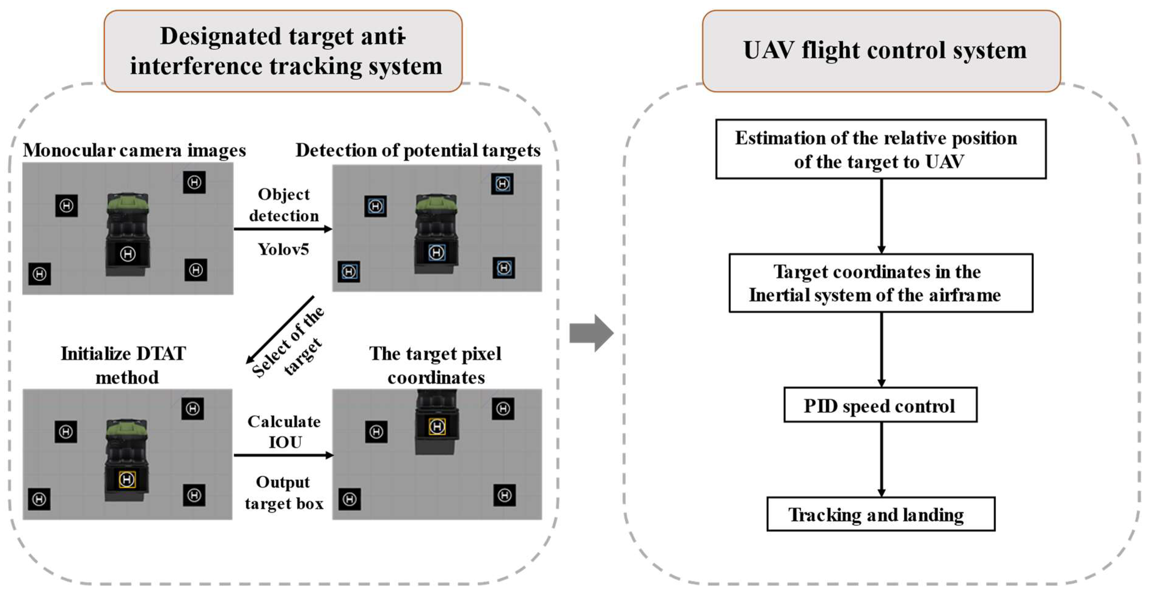
In this section, the authors introduce the UAV autonomous tracking and landing system in detail. The system hardware includes the UAV and the monocular camera. For the UAV, we selected the P450-NX produced by AMOVLAB as the experimental model, which has open-source control system code and easily completes algorithm deployment. The system uses a DF500-1944P industrial camera (Jieruiweitong Inc., Shenzhen, China), which is small in size and convenient to carry. The system software framework is shown in
Figure 1. It consists of two main parts: the designated target anti-interference tracking system and the UAV flight control system. For the former, we designed a DTAT method to enable the UAV to accurately track the target under conditions of visual interference. The system flow is shown in the panel on the left. The camera image is passed through the YOLOv5 algorithm to get all potential targets in the field of view and we select the tracking target to initialize the DTAT. When the next image frame arrives, the DTAT calculates and outputs the pixel position of the designated target frame. The flow of the flight control system is shown in the panel on the right. We use the output pixel coordinates to estimate the relative position of the UAV to the target and obtain the coordinates of the target under the inertial system of the airframe. With these coordinates used as the error term, a PID control law is used to control the flight speed of the UAV to achieve tracking and landing. The implementation process is described in detail below.
2.1. Specifying the Acquisition of Target Pixel Coordinates
The position of the designated target under the pixel coordinate system is required for the subsequent control of the UAV flight speed. For the speed and accuracy requirements of the algorithm during system deployment in the embedded environment, this paper proposes the DTAT method, integrating the YOLOv5 target detection algorithm, which has excellent accuracy performance, with the SiamRPN target tracking algorithm, which has fast speed and good embedded portability, to obtain the location of the designated target. The YOLOv5 algorithm can get the candidate frame position and size of all potential targets in the image with high detection accuracy but cannot locate the specified target. The SiamRPN algorithm uses a Siamese network to extract the given target information and is capable of tracking a single target, but the tracking accuracy is low and the target position is inaccurate. Therefore, the authors combined the two to construct the DTAT method, which ensures target tracking and improves accuracy at the same time. The implementation process of the algorithm is described in detail below.
2.1.1. Yolov5 and SiamRPN
Among target-detection algorithms, the YOLO series [
24,
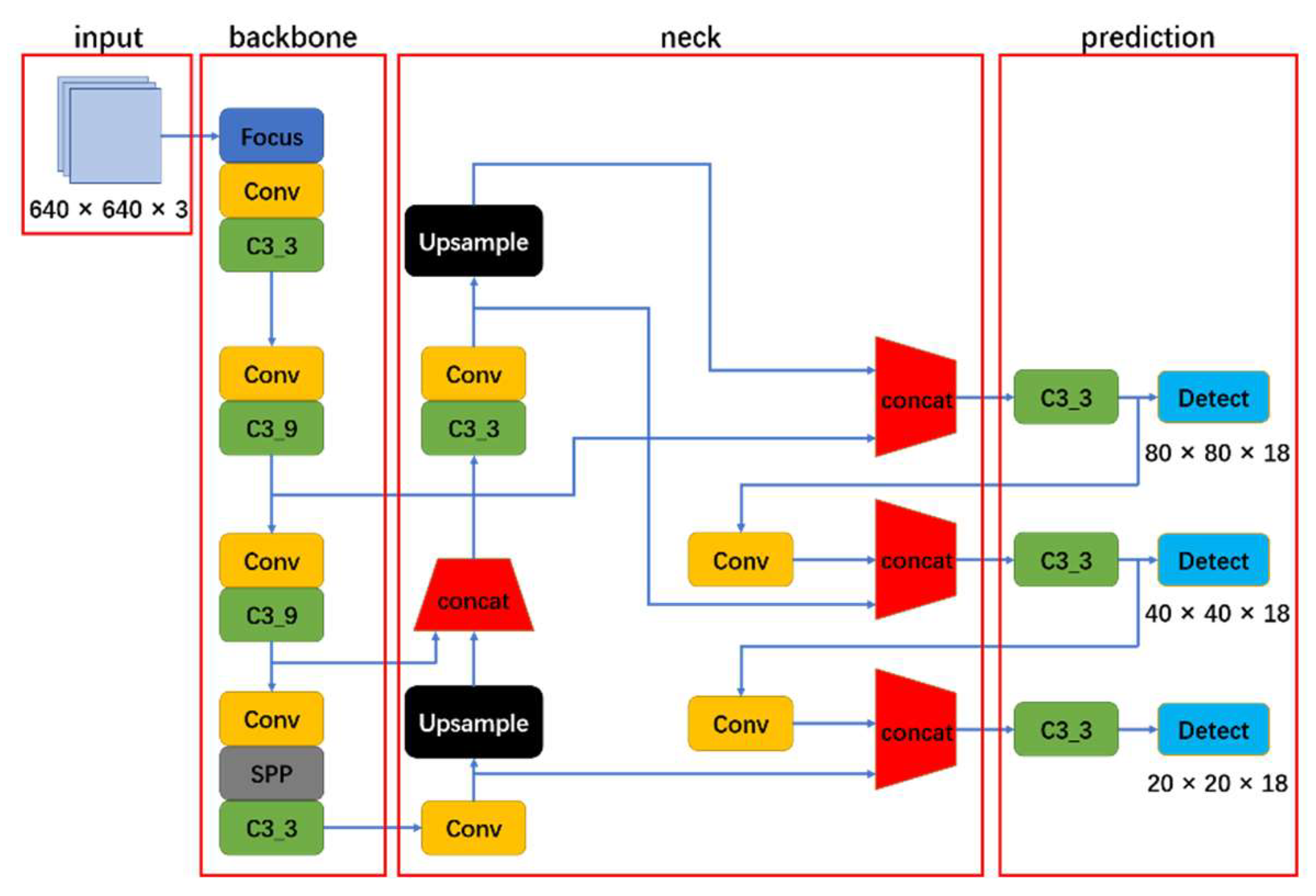
25], a single-stage detection algorithm, performs well in many official datasets. YOLOv5 (Ultralytics LLC, Washington, DC, USA) is an improved version of YOLOv4 with better detection speed and accuracy that can be deployed in embedded systems. Its network model is shown in
Figure 2; the detection results of the target are represented by the pixel box center coordinates and size.
Since the UAV processor uses the Jetson Xavier NX (NVIDIA Corporation, Los Angeles, CA, USA) embedded platform, to improve the algorithm inference speed, we use the open-source TensorRT high-performance optimized inference engine from NVIDIA. It works in three stages: network model parsing, engine optimization, and inference execution. In practical applications, TensorRT does not require any deep learning framework support to achieve the inference acceleration of the existing network models, which improves the real-time performance of the system.
SiamRPN, a single-target tracking algorithm that was proposed by Li et al. [
26] at a computer vision and pattern recognition conference (CVPR) in 2018, is used for large-scale end-to-end image training and online detection of targets in an offline environment. It addresses the problem of target interference by lighting, distortion, and occlusion in visual tracking and the time-consumption problem of traditional tracking algorithms. Due to its good real-time performance, it can be applied to airborne embedded platforms. The SiamRPN algorithm consists of a Siamese network and a region proposal network (RPN), and its network structure is shown in
Figure 3. The tracking result is determined based on the score of the classification and the offset of the regression, which means the target location and size are obtained.
2.1.2. Designation of Target Design
To build a target dataset to train the network model, the target shape and size need to be designed. In the calculation for the processing of relative position estimation, we assumed that the XY plane of the UAV body coordinate system would remain parallel to the horizontal plane of the target. For the accuracy of estimation, we designed the external contour of the target as a circular frame, making the length and width of the detection frame as equal as possible. Its outermost border was 50 cm in length and 50 cm in width, the same size as a typical landing target. To make the network learn the general features of the target and improve the recall rate when the target is occluded, we experimented with various internal markers, such as “A”, “W”, and “H”. The “H” target worked best. The overall width and height of the internal marker was 30 cm. To resist the mosaic effect, the target and background plate were patterned in white and black. The final target effect is shown in
Figure 4.
2.1.3. Designated Target Anti-Interference Tracking Method
As mentioned earlier, YOLOv5 was trained with a large-scale target detection dataset and had high model capacity and good algorithm accuracy. It can effectively detect all the target locations when the background changes, but lacks the specified target information. SiamRPN can be used for target tracking alone, but it has lower accuracy than YOLOv5 and is prone to tracking failure when the environment changes, resulting in target loss. Both algorithms are suitable for embedded platforms because of their relative lightness. To obtain the pixel coordinates of the target and improve the tracking accuracy, this paper proposes a DTAT method that integrates YOLOv5 and SiamRPN. The structure of DTAT is shown in
Figure 5.
The DTAT method first uses the YOLOv5 algorithm to detect the de-distorted images transmitted by the UAV’s on-board camera to obtain all potential target candidate frames. The tracking target is artificially specified and its YOLOv5 detection frame is used as a sampling sample to initialize the SiamRPN model. When the new image frame arrives, it is simultaneously fed into the YOLOv5 and SiamRPN networks to obtain two detection results. When there is no YOLOv5 detection result in the image, the detection result of SiamRPN is used, while the sampling sample is not updated. Intersection over union (IoU) is an evaluation metric used to measure the accuracy of an object detector on a particular dataset. When the YOLOv5 target detection results are present, the IoU and centroid distance between all target detection frames and SiamRPN detection frames are judged. When the IOU value is greater and the centroid distance is less than the set threshold, the YOLOv5 detection frame with the largest IOU value is used as the target-tracking result, and the pixel coordinates of the target frame are output; then the target frame is used as the SiamRPN sampling sample for the new image frame. If there is no target detection frame within the threshold, the SiamRPN detection result is used and the sampling sample is not updated. In summary, according to the DTAT method, the final output of the target frame information with center pixel coordinates in the image is prepared for the UAV speed control. The above IoU and distance thresholds are designed empirically and are related to the camera parameters.
2.2. Target and UAV Relative Position Estimation
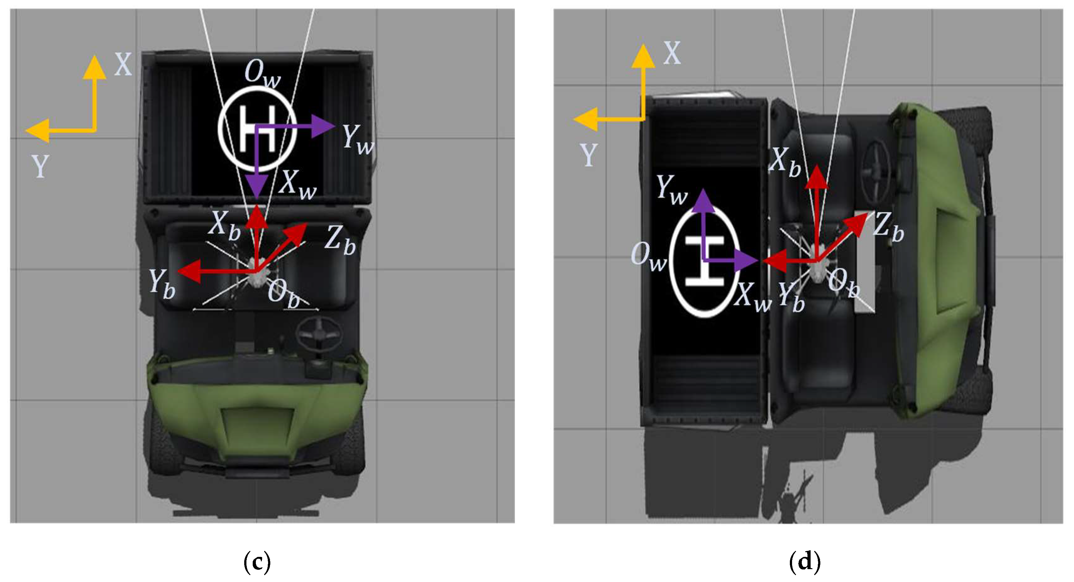
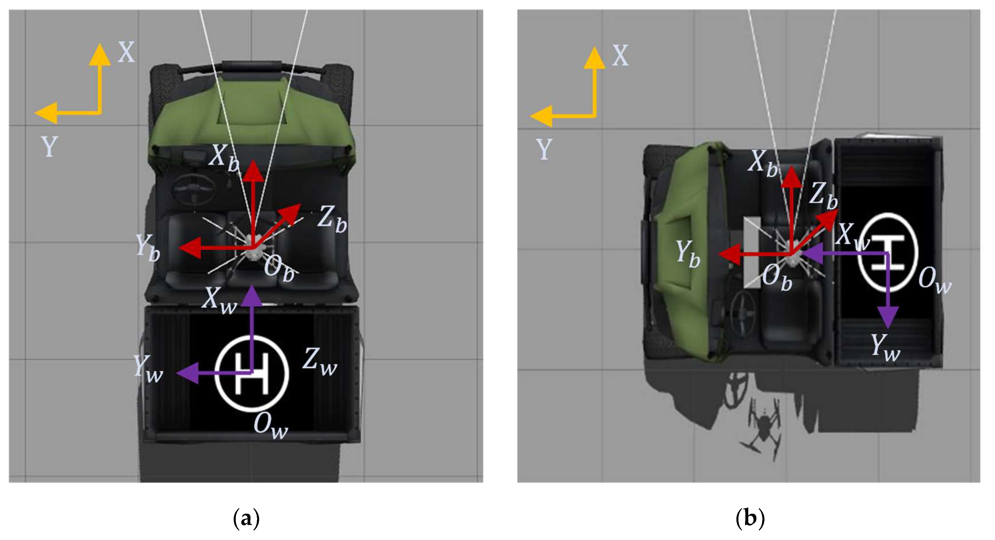
To control the flight speed of the UAV, its relative position to the target has to be calculated in real time. It is assumed that the camera is rigidly connected to and mounted directly below the UAV with the lens pointing vertically downward. Due to the compact structure of the UAV, the camera origin and the UAV body origin are considered to be the same point. The right-handed coordinate system is used as the reference to establish the coordinate system of the relative position of the UAV and the target, as shown in
Figure 6. The figure includes five coordinate systems at different levels: A, pixel coordinate system
; B, image plane coordinate system
; C, camera coordinate system
; D, target body inertia system
; and E, UAV body coordinate system
. The following describes the conversion relationship between coordinates and the relative position estimation method.
2.2.1. Coordinate SYSTEM Conversion Relationship
The image plane coordinate system is the coordinate system of the camera’s light-sensitive imaging element. If the light-sensitive size of each pixel is
and
and the coordinates of the image plane coordinate system origin
in the pixel coordinate system are (
,
), the conversion relationship between the two coordinate systems is the following equation:
Based on the pinhole imaging principle, we set the camera focal length as
and the distance from the optical center to the object as
, and the following basic relationship exists:
The relationship between the image plane coordinates
of the image point
and the camera coordinates
of the object point
is as follow:
The relationship between the pixel and camera coordinate systems can be obtained by substituting Equation (1) into Equation (3) as follows:
In the formula,
. Rewriting the above equation into matrix form, we get:
In the above equation, the matrix composed of intermediate quantities is called the internal reference matrix of camera K. In summary, the conversion relationship between pixel and camera coordinates is obtained, and the method for finding the relative position is introduced below.
2.2.2. Relative Position Estimation Method
To solve the relative position, first we solve the coordinates of the target within the camera coordinate system. Knowing
u,
v, and the internal reference matrix
K, to solve for
, the
value needs to be found first. The length of the target is the same as the width, and the actual length is assumed to be known. We use the two diagonal points of the border in the pixel coordinate system to estimate the
value. Let the two points be (
,
) and (
,
). Their corresponding camera coordinates are
and
. The relationship can be derived as the following equation:
The two equations are subtracted to obtain the following equation:
Assuming that the UAV is parallel to the target plane,
, the following equation is obtained:
This leads to the following equation:
Depth can be calculated from the target width and height. During the experiment, to address the situation where only a part of the image is in the field of view when the target is at the edge, the longer edge of the target detection is selected to calculate depth , and then the and values are calculated to obtain the coordinates of the target in the camera coordinate system.
From the above definition and as shown in
Figure 6, the origins of the camera and of the body coordinate systems are the same, dual
x-,
y-direction and opposite
z-direction, and the matrix is expressed as follows:
Based on the three-axis rotation matrix, the equation for converting from the UAV body coordinate system to the body inertial system is as follows:
In the above equation, is the rotation matrix, where , , and are the pitch, yaw, and roll angles, respectively, and the magnitudes are calculated by the UAV flight control based on the IMU information. The coordinate values , , and of the target within the body inertial system are obtained, which means that the position estimation of the UGV relative to the UAV is obtained, and then the UAV tracking and landing are controlled according to the estimated coordinate values.
2.3. Drone Tracking and Landing Control
Based on the relative position information obtained above, the three-axis velocities
of the UAV under the body inertia system need to be calculated. Since the UAV height can be controlled individually, the main focus is on the two-axis velocities
. The tracking speed is controlled by the discrete PID method during UAV tracking. Using the above relative position information as the error term, the velocity control method is established as follows:
In the equation, refer to the velocity of the UAV on the x- and y-axes of the body inertia system for the current and previous frame, respectively. are the position of the target’s current and previous frame on the x-axis under the body inertia system, respectively. are the position of the target’s current and previous frame on the y-axis under the body inertia system, respectively. is the scale factor and is the differential factor. Due to the uncertainty of the target, the UAV tracking process changes dynamically, so the integration term is not set.
For the scale factor , when is 0, the UAV control state changes to linear control; assuming the target speed is 1 m/s and the value of is 0.5, there will be a steady-state error of 2 m between the UAV and the target, which in turn leads to tracking failure. Based on the consideration of stability and oscillation reduction, = 1.5 is set, and the target may be lost when it moves too fast. To avoid oscillation, the trend of the target is predicted by increasing the differential term and = 0.6 is set.
During the UAV landing, the drone continuously tracks the target. When the detected object is located in a circular area with a radius of 0.03 m from the origin in the UAV body inertial system, the system instructs the UAV to land directly. Due to the existence of steady-state errors in the tracking process and practical considerations, the target needs to be stationary before the landing process to achieve a safe landing.
3. Results
To evaluate the performance of the autonomous tracking and landing system, a number of simulation experiments were conducted. First, to evaluate the image target tracking performance, a target tracking experiment was conducted. The experiment was divided into two parts: (1) YOLOv5 target detection and (2) DTAT target tracking. Second, we conducted experiments to estimate the relative position of the UAV to evaluate the accuracy. Finally, to evaluate the system’s effectiveness, we conducted overall UAV tracking and landing experiments.
The simulation environment uses the Jetson Xavier NX processor, which is the same as the actual UAV flight environment. The simulation environment is built based on the Gazebo function package under the ROS framework. We added an unmanned vehicle with landing landmarks and a UAV with a monocular camera to imitate the real environment of UAV flight, and the experimental procedure and results are as follows.
3.1. Experiments and Results of Target Tracking in Images
3.1.1. Yolov5 Target Detection Experiment
First, the target dataset was established. Since the UAV tracking and landing experiment was conducted in the Gazebo simulation environment, the dataset was collected by intercepting the screen in that environment. The dataset consisted of 240 target images, including five top view angles of 90°, 80°, 70°, 60°, and 50° of the
axis relative to the horizontal plane of the target, eight yaw angles of the target around the
axis, and six size occupancies of the target in the field of view.
Figure 7 shows some examples of the original and labeled target images at a top view angle of 90°, a yaw angle of 90°, and a large field-of-view occupancy.
Based on the above dataset, the YOLOv5 network model was trained and pretrained models were used. The hyperparameters were the same as the official recommendations, and the learning rate was trained with 100 epochs using cosine annealing. To qualitatively evaluate the model performance, we detected the target in a complex scene and the results are shown in
Figure 8. The YOLOv5 target detection performance was good when the camera view was tilted, the target was occluded, and the target was small (fewer than 36 pixels in the field of view). For quantitative analysis of model performance, the three indices of mean average precision (mAP)@0.5, mAP@0.5:0.95, and frames per second (FPS) of YOLOv5 and YOLOv5 + TensorRT models were compared and analyzed based on this dataset and the results are shown in
Table 1. We can see that for the YOLOv5 model, mAP@0.5 detection accuracy is 99.55%, mAP@0.5:0.95 is 87.16%, and FPS is 51.25 detection frames. YOLOv5 combined with TensorRT improved FPS by 32.2, although there was a decrease in detection accuracy, which better meets the real-time target detection task.
3.1.2. Designated Target Anti-Interference Tracking Experiment
To effectively evaluate the target tracking performance of the DTAT method, we built a multi-target disturbance scenario based on the Gazebo platform, including a UAV platform with a moving target to be tracked and one stationary disturbance target. The tracking experiments were based on video of the moving target captured by the UAV. The target moved forward while the UAV was hovering and the airframe carried a camera to collect video information. The 200 frames where the target was in the UAV’s field of view were intercepted as the target tracking evaluation dataset, and DarkLabel software was used to construct the label information of the target for model evaluation.
One-pass evaluation (OPE) [
27] was carried out, using the position of the first ground-truth frame of the target to initialize different tracking algorithms, and the recognition results of the algorithms for each frame were compared with the true value to obtain the precision rate (P) and success rate (S) to quantitatively analyze the tracking model. The results of accuracy rate and success rate of the SiamRPN and DTAT algorithms are shown in
Figure 9a,b, respectively. Due to the small dataset, both models exhibited some degree of overfitting in both the accuracy and success rate plots. To effectively differentiate the effect, we changed the accuracy rate metric to the integrated area of the curve with respect to the x-axis, as shown in the figure legend. On the precision rate index, the DTAT method performed better at a low pixel threshold with high tracking accuracy. On the success rate index, the DTAT method could still recall the target under a high IOU threshold, and the tracking regression rate was high. In summary, compared with the single SiamRPN algorithm, the DTAT method performed better.
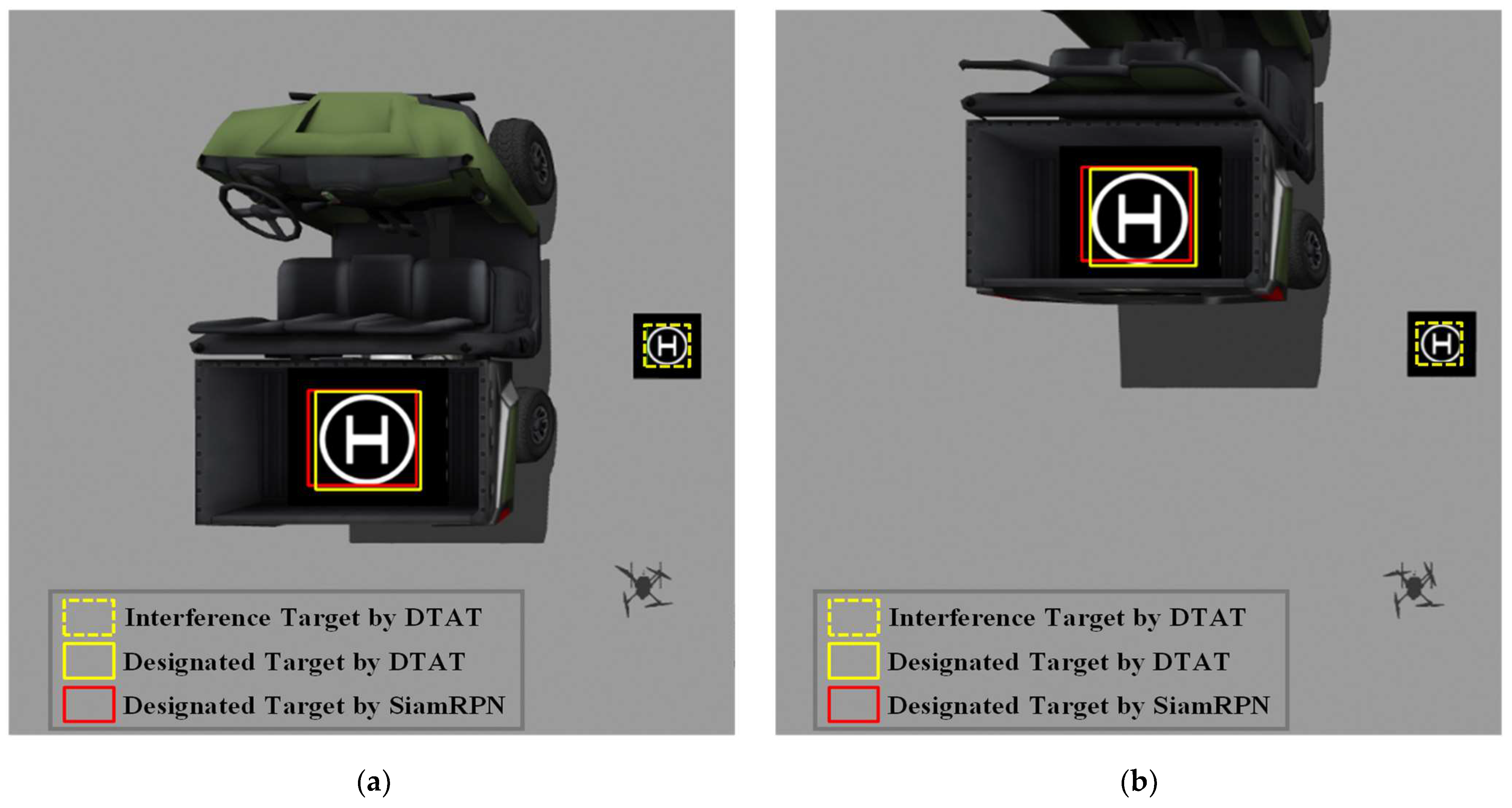
We selected frames 20 and 167 to show the tracking results, as shown in
Figure 10. The yellow dotted and solid boxes shown in the figure represent the interference target and designated target obtained by the DTAT method. The red box represents the tracking of the designated target obtained by the SiamRPN algorithm. Both
Figure 10a,b showed that the DTAT algorithm was able to distinguish between the specified target and the interfering target, and also had higher tracking accuracy for the designated target compared with the SiamRPN algorithm.
3.2. Simulation Experiments and Results of Relative Position Estimation
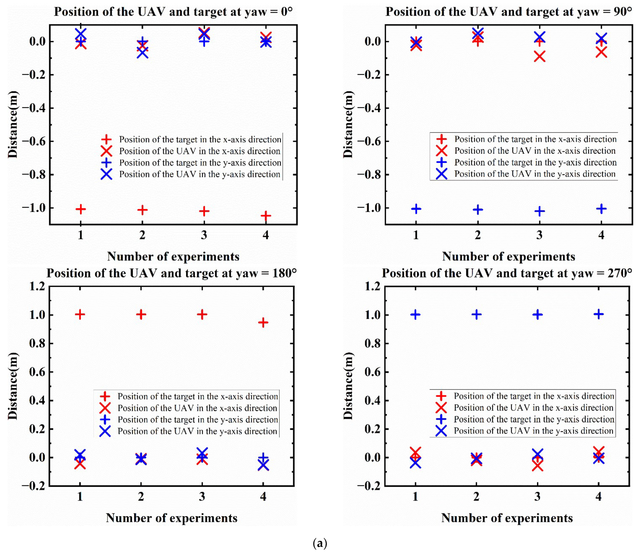
Based on the pixel coordinates obtained by DTAT, we estimated the relative positions of the UAV and the ground target. To verify the effectiveness of relative position estimation, we estimated the relative position of the UAV to the target in the following four cases. As shown in
Figure 11, the target was placed on the ground and the drone was in hovering mode. The yaw angle of the body rotation relative to the UAV system
was 0°, 90°, 180°, and 270°. To eliminate the occasional factor, the experiment was repeated four times at each yaw angle.
Based on the monocular camera information from the UAV, the pixel coordinates of the target were detected and the relative position was estimated. The estimation bias was obtained by subtracting the estimated value from the true value provided by Gazebo to verify the estimation effect, and the experimental results are shown in
Figure 12.
Figure 12a shows the real positions of the target and the UAV provided by Gazebo, that is, the coordinate positions of the
x- and
y-axis. The target and UAV coordinates were subtracted to obtain the true value of the relative position.
Figure 12b shows the estimated value obtained by the relative position algorithm and the true value obtained by the true position calculation. Finally, the results of four replicate experiments for each yaw were summarized to obtain the errors of relative position estimation in the
x- and
y-directions in 16 experiments, as shown in
Figure 12c.
As shown in
Figure 12c, the error range of the relative position estimation algorithm with a static target was no more than 8 cm maximum error in the
x-direction and 15 cm in the
y-direction. The experimental results indicate that the relative position estimation algorithm met the UAV tracking and landing accuracy requirements.
3.3. Target Tracking and Landing Simulation Experiments and Results
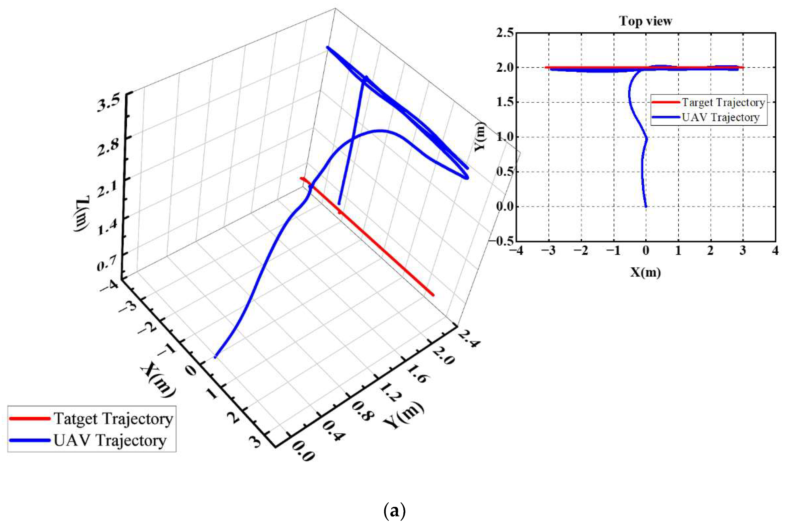
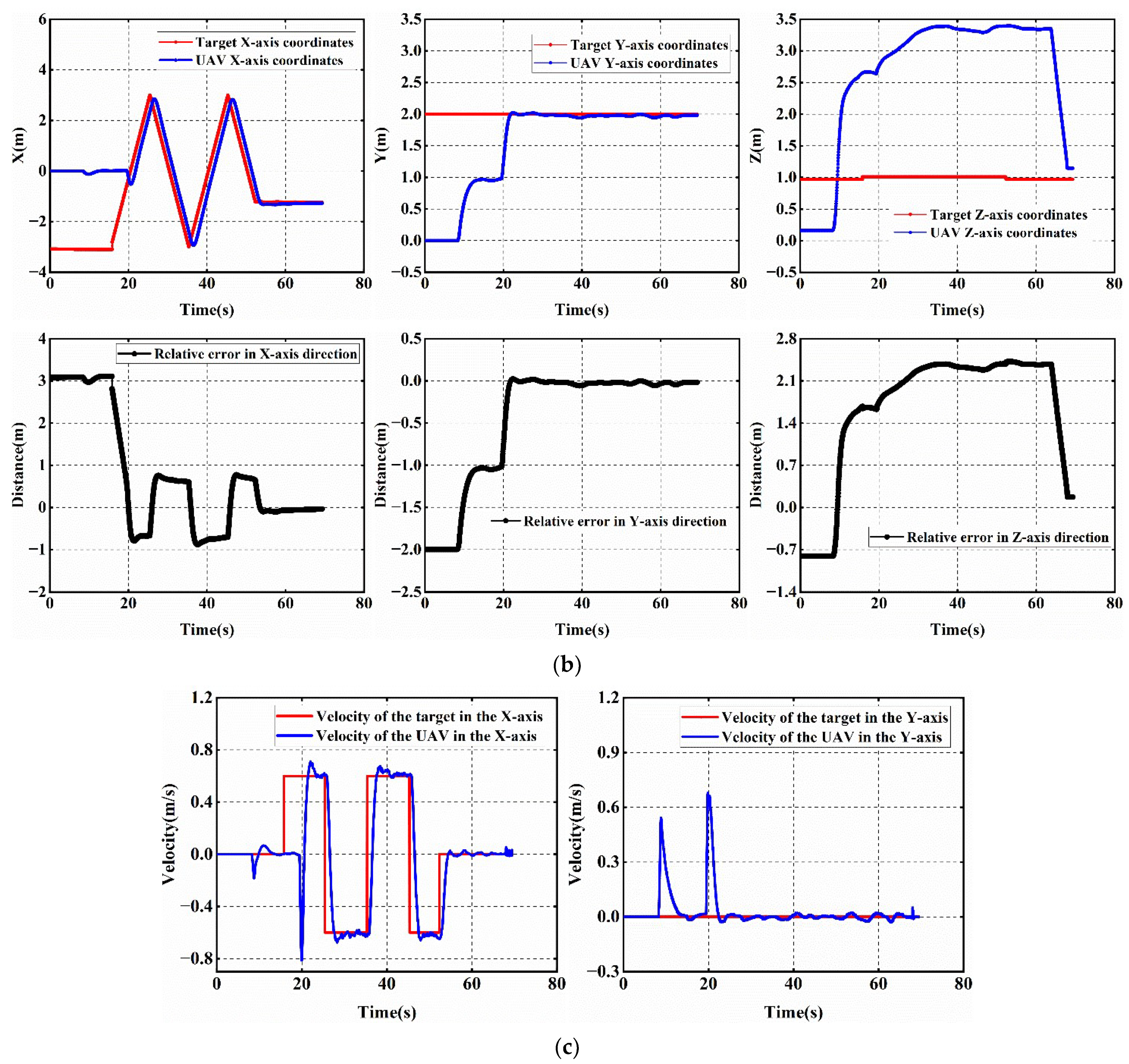
To effectively evaluate the performance of the system, we designed a simulation experiment of UAV tracking and landing. The target was set to move along different paths (reciprocal straight line, circle, and rectangle), and the UAV tracked the target after a period of time and landed when the target was stationary. We chose the reciprocal straight-line trajectory for quantitative analysis, and the experimental results are shown in
Figure 13. It should be noted that the effective estimated height range of the airborne monocular camera was about 0.3–6 m. When the flight height of the UAV was higher than the effective range of the camera, the position estimation would be inaccurate. Therefore, the flight height of the UAV was controlled within the effective range.
Figure 13a shows the process of target tracking and landing of the UAV. The red and blue paths represent the real position trajectory curves of the target and the UAV, respectively. First, the UAV took off to the designated point, while the target made a circular reciprocal motion along the
x-axis at 0.6 m/s. It can be seen from the
Figure 13a that the UAV constantly followed the moving ground target, conformed to the target motion curve in the
x- and
y-directions, and maintained a relatively fixed height difference with the target in the
z-direction.
Figure 13b shows the tracking results of the UAV in the three axis directions with errors. As shown in the figure, the errors ranged from −0.8 to 0.8 (m) and −0.2 to 0.2 (m) in the
x- and
y-directions, respectively. During the motion, the relative height of the
z-axis was set to 2 m, and the real-time error was up to 0.5 m. When the target was stationary and the UAV started to land, the landing error of both
x- and
y-axis was 0.01 m, indicating high landing accuracy.
Figure 13c shows the real-time velocity of the UAV and the target, indicated by two colors. From the figure, it can be seen that the UAV’s operation speed tended to be close to the real speed of the target, and when the target speed changed, the UAV could react faster and track the target continuously.
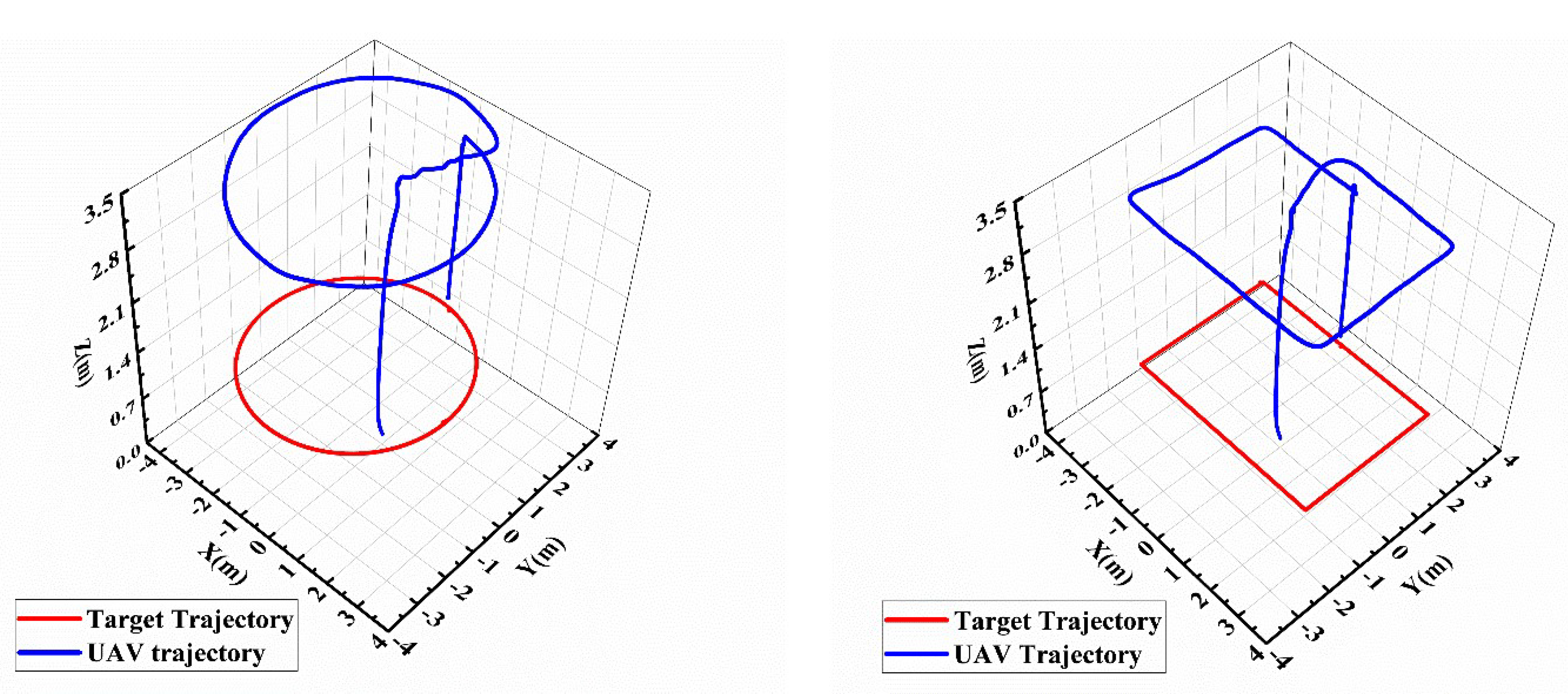
Figure 14 showed the UAV’s following trajectory results when the target was moving in a circular and rectangular shape. When the target was moving at 0.4 m/s in rectangular and circular trajectories, respectively, the UAV’s tracking trajectory matched the target’s running trajectory and the system still worked well, although it could not overlap the target in real time.
4. Discussion
With the above experimental results, we can eliminate the influence of interfering targets in the tracking process. The tracking system based on the DTAT method has more advantages of anti-interference and tracking accuracy compared with other tracking systems mentioned before. In this section, we further discuss the factors that affected the performance of the UAV tracking and landing system. First, for the DTAT method, we analyze the reasons for the method design and discuss the experimental results to propose the factors that affect the performance of the method and possible improvements. Second, for the relative position estimation experiments, the reasons affecting the experimental accuracy are analyzed. Finally, the overall situation of the system is discussed, and the limitations and areas for improvement are analyzed.
4.1. DTAT Method Design and Performance Analysis
The DTAT method combines YOLOv5 and SiamRPN, two algorithms used for target detection and tracking. The system was not designed using only a tracking algorithm based on the following considerations: the SiamRPN algorithm trains the target based on video frames, which has smaller data volume and fewer scenes. At the same time, the model capacity is smaller and the tracking accuracy is lower compared to the target-detection algorithm. The DTAT method is based on the advantages of the target-detection method and uses a large-scale image dataset, and the model has a better detection effect, while incorporating the target-tracking algorithm, which can achieve tracking of a specified target. In addition, target-detection and -tracking algorithms are now more widely studied; this paper mainly considers the features of light weight and portability and selects two classical algorithms, YOLOv5 and SiamRPN; the use of other model combinations can be considered in subsequent research.
In the tracking experiments using the DTAT method with the SiamRPN algorithm for a specified target, it can be seen from
Figure 9 that SiamRPN had very low or even zero accuracy at low pixel thresholds. The DTAT method can quickly improve the accuracy at low pixel thresholds, which shows that the YOLOv5 algorithm is more robust in the tracking process and SiamRPN is easily affected by the results of the previous frame and has poor tracking accuracy. DTAT performs better in success-rate tracking experiments compared to SiamRPN and easily tracks targets, presumably mainly because the large YOLOv5 dataset provides robustness to target background changes and improves target recall.
In the DTAT method, we place the YOLOv5 detection results at a higher confidence level, but because of the limitations of the training dataset, background environmental noise, and the scaling of the field of view caused by the different flight altitudes of the UAV, sometimes neither target detection nor tracking can obtain accurate pixel coordinates, which in turn affects the relative position estimation of the target and leads to UAV tracking and landing failure. To effectively estimate the pixel coordinate position of the target, subsequent experiments could add Kalman filtering. When the target is within a certain distance threshold, only the original target detection result is used instead of the Kalman filter to fuse the target detection and tracking results, with the YOLOv5 detection result as the measured value and the SiamRPN tracking result as the state value, so as to estimate the target pixel coordinates and obtain improved accuracy.
4.2. Performance Analysis of Relative Position Estimation Method
The UAV was fixed and the target was placed around the
z-axis of the UAV body system at four angles, and four sets of static estimation experiments were performed for each angle to verify the effectiveness of the relative position estimation algorithm. The final estimation error is shown in
Figure 12c. It can be seen that each group of experiments had a certain regularity. When the
x-axis of the target was parallel to the global
x-axis, the relative position estimation method had a larger deviation in the
x-direction and a smaller deviation in the
y-direction. When the
x-axis of the target was parallel to the global
y-axis, the relative position estimation method deviated more in the
y-direction and less in the
x-direction. These deviations are always present, independent of the target’s position in the airframe. We can conclude that the relative position estimation method is inaccurate in estimating the position of the target in the
x-direction, i.e., the direction of the two long edges of H, and relatively accurate in estimating the position of the target in the
y-direction, i.e., the direction of the shorter middle edge of H.
Therefore, the factor affecting the relative position estimation may be the training accuracy of the YOLOv5 network model, which is more accurate when it is better trained for the short-edge direction. Poor training for the long-edge direction results in lower accuracy. In actual flight, the UAV will have a certain degree of offset, which does not meet the assumptions of the relative position estimation algorithm and will therefore also produce a certain degree of error. To improve the relative position estimation accuracy, a model with higher accuracy can be selected for tracking, while controlling the degree of UAV offset and reducing the violent jitter during flight.
4.3. Tracking and Landing System Analysis and Constraints
In this system, the UAV uses a Jetson Xavier NX processor for autonomous tracking and landing. To evaluate the execution efficiency of the system, we built the same experimental simulation environment based on the ROS system framework. The environment consists of four nodes: the gazebo simulation node, the pix4 feedback node, the target detection and tracking node, and the nonlinear control node. The environment was deployed in the Jetson Xavier NX processor, and the processing time of each module is shown in
Table 2. The system took 30.44 ms from inputting a picture to the UAV performing flight control, generating roughly 33 Hz to meet the actual flight requirements.
Through qualitative and quantitative analysis, this paper verifies the tracking performance of a system for a designated target in the case of multi-target confusion; however, there are still some limitations of the system, mainly the following two aspects:
- (1)
The flight control algorithm takes the relative position of the airframe and the target as input variables and uses feedback PID control, so there is a certain steady-state error in the tracking process. In the process of following the target at low altitude, if the target moves too fast, it will rush out of the UAV’s field of view and the UAV cannot respond effectively, which in turn leads to the failure of target tracking.
- (2)
The system needs to have real information about the target in advance. The YOLOv5 detection process requires datasets made by real targets, and the relative positional solution process relies on the real size information of the target. In the actual tracking process, it is difficult to track unfamiliar targets.
5. Conclusions
In this paper, we proposed a DTAT method and built an autonomous UAV tracking and landing system that enables UAV tracking and the landing of a designated target in an environment with multiple interference targets. The image information transmitted by the monocular camera was processed by DTAT and coordinate transformation to obtain the spatial coordinate information of the specified target; then, the discrete PID control method was adopted to realize tracking and the landing of the UAV on the designated target.
Extensive simulation experiments were conducted to evaluate the system performance. The effectiveness and reliability of the algorithm and system were analyzed qualitatively and quantitatively with regard to various aspects, such as the target pixel coordinates, the position of the UAV relative to the target, and the tracking and landing process. The results show that the relative distance between the UAV and the target during the tracking process when the target was moving at 0.6 m/s did not exceed 0.8 m. The landing error of the UAV during the landing process after the target was stationary did not exceed 0.01 m. In addition, the advantages and disadvantages of the system were discussed at the level of both processor hardware and algorithm design, and corresponding suggestions were made for different problems. In the future, we will use multi-sensor fusion, such as radar and a depth camera, to achieve target tracking and landing without a priori information, and explore more intelligent and stable tracking algorithms to make UAVs more adaptable to complex environments.


