Article

Ultra-Low Sidelobe Waveforms Design for LPI Radar Based on Joint Complementary Phase-Coding and Optimized Discrete Frequency-Coding

1
School of Electronics and Communication Engineering, Shenzhen Campus, Sun Yat-sen University, Shenzhen 518107, China
2
School of Electronics and Communication Engineering, Sun Yat-sen University, Guangzhou 510275, China
*
Author to whom correspondence should be addressed.
Remote Sens. 2022, 14(11), 2592; https://doi.org/10.3390/rs14112592
Submission received: 23 April 2022 / Revised: 8 May 2022 / Accepted: 25 May 2022 / Published: 28 May 2022
(This article belongs to the Section Engineering Remote Sensing)

Abstract

:
In this paper, in order to reduce the probability of the radar waveform intercepted by the passive detection system, the time-bandwidth product of the radar waveform is increased, and the detection probability of the radar waveform to the target is improved. This paper tackles the holographic RF stealth radar and proposes a joint coding waveform based on the linear frequency modulation (LFM) waveform. Joint coding uses complementary codes to perform phase-coding, and combines the codewords optimized by genetic algorithm in order to perform discrete frequency-coding waveform. The joint coding waveform model is theoretically analyzed, and the ambiguity function, pulse compression and target detection probability of the joint coding waveform are obtained by numerical simulation. In addition, the complexity of the algorithm and the low probability of intercept (LPI) characteristic of the joint coding waveform are analyzed. The results show that the joint coding waveform has an approximate “pushpin” ambiguity function, ultra-low sidelobe characteristics, better RF stealth and target detection performance. Finally, it has good application prospects in the current battlefield environment.

Graphical Abstract

1. Introduction

As a kind of radio detection equipment, radar has the advantages of all-weather, all-time and robust penetration ability. It plays a crucial role in war, disaster relief and civil use [1,2]. It faces an unprecedented substantial threat in modern warfare dominated by science and technology. The rapid development of high-sensitivity radar signal interception technologies puts most of the radars at risk of being exposed when they are turned on, which increases the probability of combat mission failure. Therefore, quickly obtaining battlefield intelligence while reducing the probability of a radar being recognized and intercepted, is a problem that should be urgently solved [3].
In order to reduce the risk of radar signals being detected by interceptors and gain the initiative on the battlefield, the RF stealth technology has been developed in recent years [4]. The stealth aims at keeping the enemy in an environment of constant guessing, making it challenging to decipher its active feature information or submerging its information in a noisy environment. In addition, it cannot be efficiently accumulated for a long time. The method of active feature reduction is referred to as Low Probability of Intercept (LPI) technology [5]. In order to improve the LPI performance of radar, the primary processes at this stage are the complex radar waveform design and radar peak power control [6].
The radar waveform theory is an essential branch of radar theory. The radar waveform directly or indirectly determines the radar’s primary performance and signal processing method [7,8]. With the increasing complexity of the current battlefield environment, the radar LPI waveform design has become a meaningful approach to optimize the radar performance in a radar system. Sun and Lu [9] study the characteristics of UWB signals and random signals. They combine the two to propose a UWB random mixed-signal, which improves the performance of radar detection and parameter estimation. Witte, E.D. [10] studies the waveform of the ultra-low sidelobes radar signal. The nonlinear frequency modulated signal has 70 dB sidelobes. However, it is very sensitive to Doppler shift. Dietl G [11] studies a hybrid waveform design method based on the beamforming and space-time block coding of the dual-channel model. He also compares and analyzes the signal-to-noise ratio of optimal linear precoding and orthogonal space-time block coding. Kassab R [12] proposes the ambiguity function and signal waveform design algorithm of quasi-continuous wave radar, which can better solve the shadowing problem of the echo signal of quasi-continuous wave radar. Geroleo F G and Brandt-Pearce M [13] study the LPI performance of Linear Frequency Modulation (LFM) continuous wave radar signals. The software degree is low because the traditional radar transmits waveform mode integrated into its system. In addition, the conventional radar transmits waveform mode integrated into its design, and the transmit wave technology is relatively single under the existing technology. In fact, it is challenging to use frequency-coding or phase-coding waveforms to achieve waveform agility. When the radar transmits large time-bandwidth products, the LPI waveforms become very difficult. They are more likely to intercept the enemy receivers by simple pulse compression, limiting our own radar’s LPI performance.
At present, the radar mainly transmits the LFM waveform, and it is one of the earliest and most widely used LPI pulse compression signals [14]. However, the LFM waveform can obtain a large time-bandwidth product using the pulse compression technology, making the matched filter insensitive to the Doppler frequency shift of the echo signal. A disadvantage is that the output response generates an additional delay proportional to the Doppler shift [15]. Compared with the LFM waveform, the coding waveform is used to improve the symbol diversity of the modulated carrier frequency signal. The anti-interference ability of the phase-coding signal is relatively strong. However, the phase-coding signal is quickly limited by the width of the sub pulse symbols [16,17]. The simple frequency-coded waveforms, such as stepped frequency waveforms, have larger equivalent bandwidths. However, compared with the discrete frequency coded waveforms, their spectral modulation laws are relatively simple, and easily detected by interceptors [18]. The joint modulation waveform refers to the combined signal waveform modulation using two or more modulation methods [19]. Hou [20] analyzes the self-ambiguity and mutual-ambiguity functions of the hyperbolic frequency hopping-Barker code radar signal. He also verifies the LPI of the signal by simulation. The authors in [21,22] study the mixed modulation radar signal based on linear frequency modulation and Taylor four phase-coding. They analyze the signal’s range resolution, velocity resolution and LPI performance. In addition, they design an LPI signal with a “pushpin” ambiguity function. Yang [23] proposes a method of mixed modulation radar signal based on tangent frequency modulation and bi-phase Barker code, while suppressing the spectral sidelobes of the signal. The authors in [24,25,26] design a new Frequency Shift Keying (FSK)/Phase Shift Keying (PSK) mixed-signal for the high resolution, large time-bandwidth product, anti-interference and low interception of FSK signal and PSK signal. The simulation results show that the signal has high range and velocity resolution, as well as a high measurement performance. Compared with a single FSK signal or PSK signal, its LPI is significantly improved. However, this study uses a relatively mature method to modulate the transmitted waveform. The waveform coding method is easy to be deciphered by the intercepting receiver. The advantage of the joint coding waveform is that it can obtain a large time-bandwidth product. In addition, it has the characteristics of single modulation between signal waveforms to complement each other, which improves the distance and speed resolution of the signal waveforms. Moreover, the joint modulation waveform can improve the pseudo-randomness of the signal, which significantly reduces the probability of the signal being monitored, identified and tracked by the intercepted receiver.
In this paper, a phase-frequency joint coding radar LPI waveform is designed using the characteristic of complete software of holographic radar [27]. Based on the LFM waveform, a new LPI radar waveform with a large time-bandwidth product is formed, using complementary code for complementary phase-coding (CPC) and combined with discrete frequency-coding (DFC) optimized by the genetic algorithm (GA). The performance of the waveform is then analyzed. The main contributions of this paper are summarized as follows:
(1)
Using the characteristics of complementary inter-code cancellation and zero autocorrelation sidelobe, the phase-coding waveform is designed to increase the peak sidelobe ratio of the transmitted waveform. GA optimizes the DFC to form a new GADFC codeword, which increases the orthogonality between the codewords and reduces the autocorrelation sidelobe level.
(2)
A CPC-GADFC joint coding waveform based on LFM is designed. The joint coding waveform can make up for the drawbacks of a single modulation waveform, and enhance the radar waveforms’ LPI and anti-interference abilities to ensure the radar range and speed measuring resolution.
(3)
Through the combination of CPC and GADFC, the echo pulse compression of the radar transmit waveform has the characteristics of ultra-low sidelobes, and the main lobe width is narrower so that the designed waveform has more advantages in target detection.
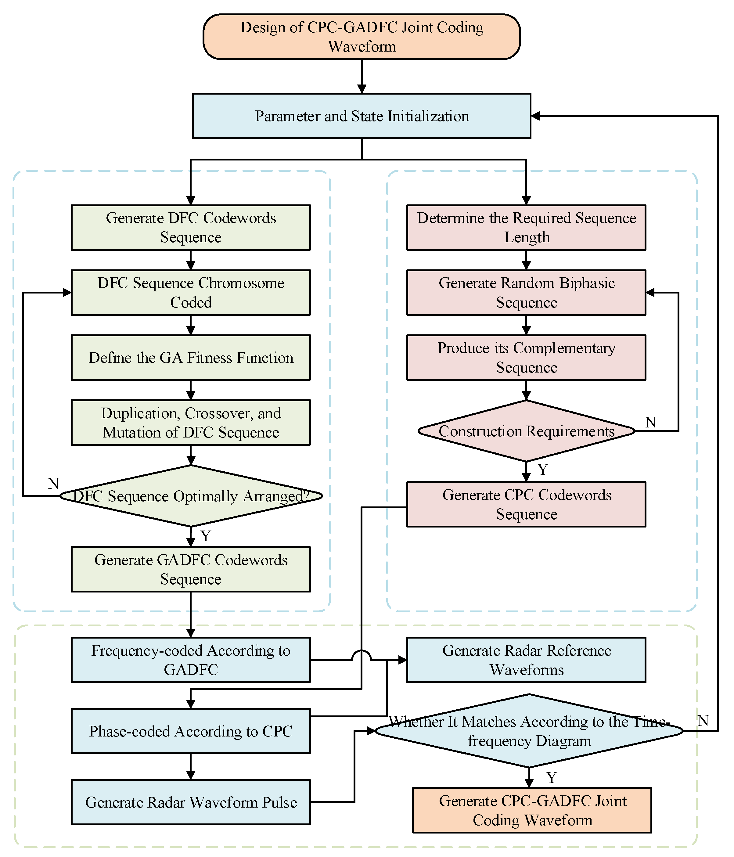
The remainder of this paper is organized as follows. Section 2 introduces the algorithm model, which focuses on the phase encoding of the complementary code sequence and the frequency encoding using the discrete frequency sequence optimized by the GA. Section 3 presents the CPC-GADFC joint coding waveform design, performance analysis and processing method analysis. The CPC-GADFC joint coding waveform expression is also deduced, and the performance analysis and processing method design are performed. Section 4 details the simulation experiment which verifies the performance of the designed CPC-GADFC joint coding waveform based on LFM. Finally, the conclusions are drawn in Section 5.

2. Algorithm Model

Based on the LFM waveform, this paper designs a CPC-GADFC joint coding waveform. In phase, the complementary code sequence is used for phase-coding, while in frequency, the discrete frequency sequence optimized by the GA is used for frequency-coding waveform. This section mainly introduces the complementary code phase-coding model and GA for DFC optimization.

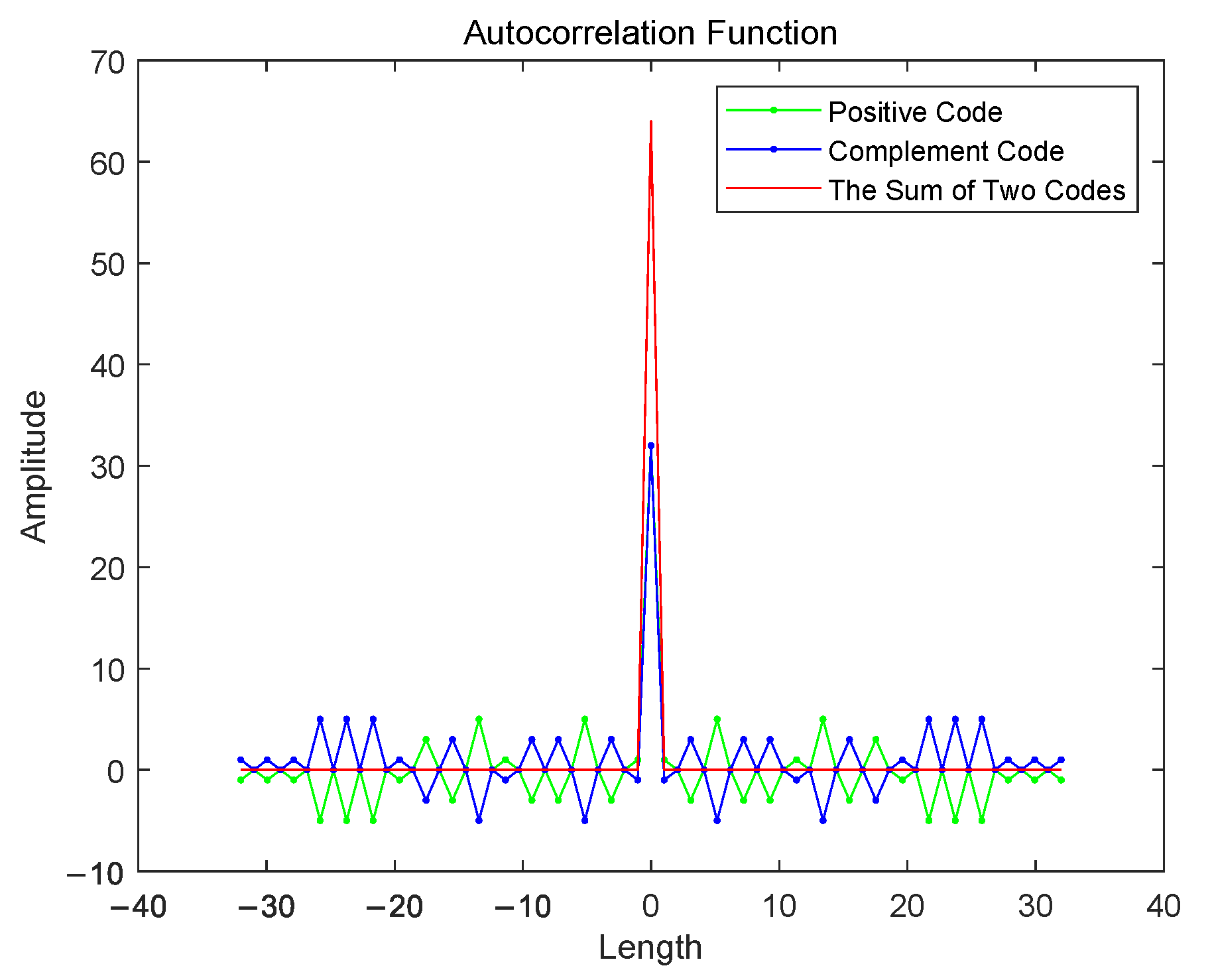
2.1. Complementary Code Model

Golay and Erickson [28,29] propose a different technique, referred to as complementary codes, in order to reduce the length of binary sequences of finite length. The complementary sequences are two sequences having the same length, with orthogonal autocorrelation sidelobe levels. When the autocorrelation functions of the two sequences are added, their peak level reaches the highest level, and the sidelobe level is zero.
The definition of complementary two-phase code is given by: there are two-phase sequences of length N, positive code c A and complement code c B , where the logarithm of the same element in positive code c A is equal to the logarithm of the same component in complement code c B , then the positive sequence code c A and the complement code c B form a complementary code, and the length of the complementary code should meet N = 2 r 10 s 26 t , where r, s and t are non-negative integers, and N should be the sum of the squares of two integers. The aperiodic autocorrelation functions of positive code c A and complement code c B are respectively R c A ( m ) and R c B ( m ) . If the following relationship is satisfied:
R c A ( m ) + R c B ( m ) = 2 N , m = 0 0 , m 0 ,
then c A and c B form a complementary code pair. The complementary codewords used in this paper are:
c A ( m ) = [ 1 , 1 , 1 , 1 , 1 , 1 , 1 , 1 , 1 , 1 , 1 , 1 , 1 , 1 , 1 , 1 , 1 , 1 , 1 , 1 , 1 , 1 , 1 , 1 , 1 , 1 , 1 , 1 , 1 , 1 , 1 , 1 ] , c B ( m ) = [ 1 , 1 , 1 , 1 , 1 , 1 , 1 , 1 , 1 , 1 , 1 , 1 , 1 , 1 , 1 , 1 , 1 , 1 , 1 , 1 , 1 , 1 , 1 , 1 , 1 , 1 , 1 , 1 , 1 , 1 , 1 , 1 ] .
The complementary code’s autocorrelation function is determined (cf. Figure 1) according to Equation (1) and the codewords (2) used in this paper.
It can be seen from Figure 1 that the autocorrelation function of the c A and c B autocorrelation functions at 0 is 2 N , which meets the construction requirements of complementary codes.
The characteristics of complementary code have two sequences. In order to reduce the influence of the echo performance fluctuation caused by angular scintillation of the target effective reflection area, in a pulse group transmitted by radar, the pulse is transmitted by alternating phase modulation of positive code c A and complement code c B , as shown in Figure 2.
It can be observed from Figure 2 that in a pulse group, the radar pulse alternately transmits the positive code c A phase modulation waveform and the complement code c B phase modulation waveform at a pulse repetition interval of τ . By alternately transmitting, the echo pulse compresses the sidelobe level using the autocorrelation characteristic of the complementary code.

2.2. Genetic Algorithm

The GA is based on Darwin’s theory of evolution and Mendel’s genetics theory. The theory of evolution proposes that species constitute a complex process that is not random through step-by-step evolution. This paper uses the GA to find the optimal codeword combination of DFC, increase the orthogonality between codewords, and reduce the sidelobe level of the GADFC autocorrelation function.
GA is used to represent the problem as a “chromosome” -like representation of strings coding in binary or floating-point numbers. A group of “chromosomes”, namely the initial population (hypothetical solution set), is then given. These hypothetical solutions are placed in the “environment” of the problem. According to the principle of survival, the fittest and its survival, as well as the “chromosomes” that are more suitable for the environment, are considered for the process of replication, crossover and variation in order to produce a new generation of “chromosome” groups that are more suitable for the environment. It finally converges to a “chromosome” that is most suitable for the environment through continuous evolution. After decoding, an approximately optimal solution to the problem is obtained. The basic steps of the GA are summarized as follows:
(1)
Chromosome coding. The optimal arrangement between DFC codewords is converted into a search space that the GA can process with Gray encoding. Since the codewords of DFC are decimal, it is necessary to first convert them into binary representation. The variation range of the DFC codewords is [ a ,   b ] , the encoding length is l and the encoding precision of the binary encoding is ( b a ) / ( 2 l 1 ) . The conversion relationship between the DFC binary codewords and its decimal is given by:
a = a min + b 2 m 1 ( a max a min ) ,
where a is an argument between [ a min , a max ] and b is a m-bit binary code represented as B = b m b m 1 b 2 b 1 .
Using Gray coding can enhance the local search ability of the GA. The Gray code corresponding to binary code B is G = g m g m 1 g 2 g 1 . The conversion equation between binary code and Gray code is expressed as:
g i = b i + 1 b i , b i = b i + 1 g i , i = m 1 , m 2 , , 1 ,
where ⊕ denotes the exclusive-or operation, that is, when the two numbers are the same, it leads to 0, and when they are not, it leads to 1.
(2)
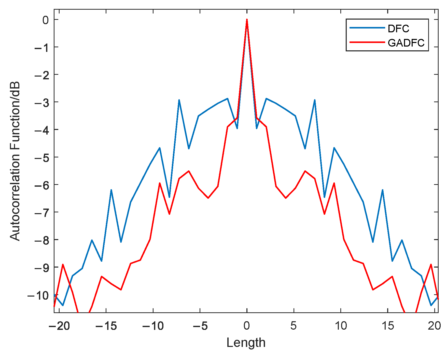
Define the fitness function and generate the initialization population. Before using the GA, the fitness function should be used to determine the final goal. In this study, the maximum Euclidean distance of DFC should be found. That is, the objective function is the optimal codeword combination mode to form a new GADFC codeword and achieve a lower sidelobe autocorrelation level. The objective function is given by:
D G A D F C ( g i * , g i + 1 * ) = m a x E u d [ D D F C ( g i , g i + 1 ) ] ,
where m a x E u d represents the maximum Euclidean distance between two adjacent codewords after gray coding, D D F C passes through the fitness function, g i is the Gray codeword and g i * is the target optimal codewords arrangement.
In order to ensure the diversity of chromosomes in the population, while ensuring the regular operation of the genetic algorithm, the dispersion of chromosome fitness values is improved, and the high performance of the GA algorithm is ensured. It is necessary to transform the objective function into a function of the fitness function by an exponential transformation:
f ( Z ) = exp ( β Z ) ,
where Z = D G A D F C ( g i * , g i + 1 * ) is the optimization objective function, f ( Z ) is the fitness function and β is the optimization coefficient which is usually a constant.
(3)
Select replication, crossover and mutation operations on the obtained population to generate the next generation population. This selection is the key to GA. It is based on the evaluation of individual fitness, while the purpose is to avoid gene deletion and improve the global convergence. The crossover consists in selecting a more significant value of the random number than the crossover probability for the next step. The mutation first selects some individuals from the population with a certain high probability, and performs the inverse operation on each chosen individual. In this paper, the probability of mutation is 0.001. The global search ability of the GA is mainly provided by selection, crossover and mutation. The mutation ensures that the algorithm can search every point from the problem space to the solution space, making the algorithm have global optimality and enhancing the GA’s robustness.
(4)
Determine whether the algorithm satisfies the stopping criterion. If it is not satisfied, then repeat step (3).
(5)
The algorithm ends, and the optimal GADFC codewords are obtained.
The DFC coding and GADFC coding autocorrelation functions are then compared (cf. Figure 3).
Figure 3 shows that the GADFC coding autocorrelation sidelobe level generated by the GA is significantly lower than that of the DFC coding. The waveform generated by frequency-coding LFM waveform with GADFC has satisfactory low sidelobe characteristics. Considering that the optimization of the DFC codeword by GA can improve the orthogonality between radar transmitted pulses, the waveform correlation coefficients of two adjacent transmitted pulses shown in Figure 2 are used for analysis (cf. Table 1).
It can be seen from Table 1 that GADFC efficiently reduces the correlation coefficient between adjacent pulses, increases the orthogonality, and more efficiently improves the radar waveform target detection performance.

3. Cpc-Gadfc Joint Coding Waveform Design, Performance and Processing Method Analysis

The expression of the CPC-GADFC joint coding waveform is deduced, and the performance analysis and processing method design are performed, according to section II of the complementary code phase-coding model and the results of DFC optimization by GA.

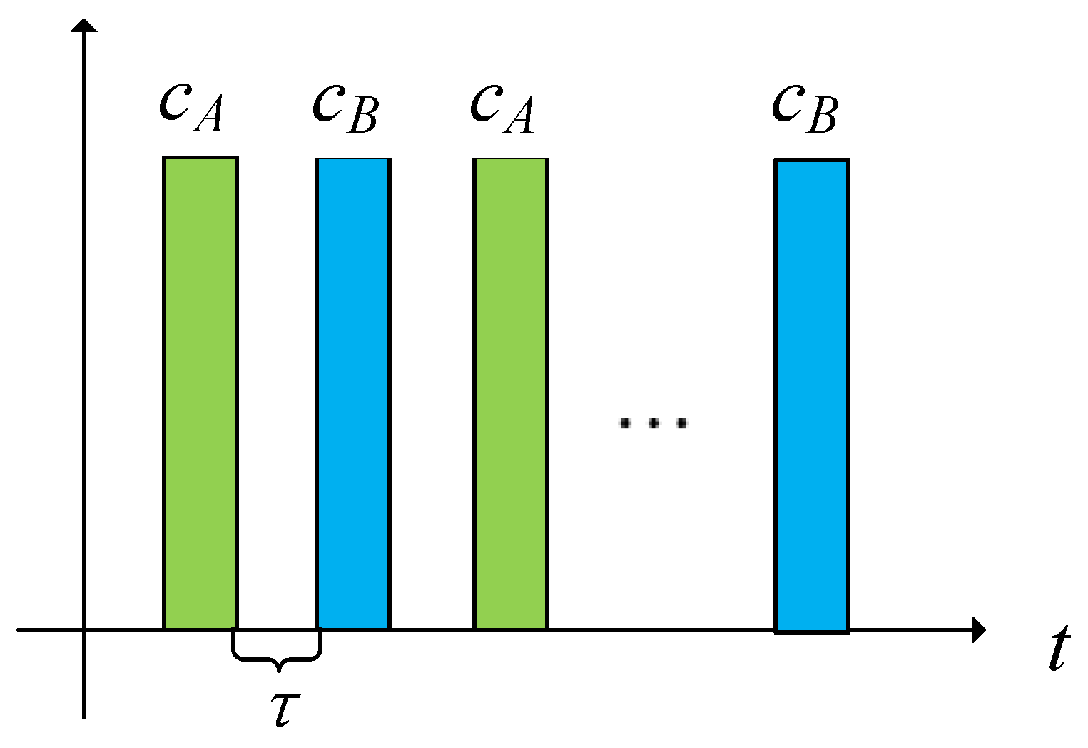
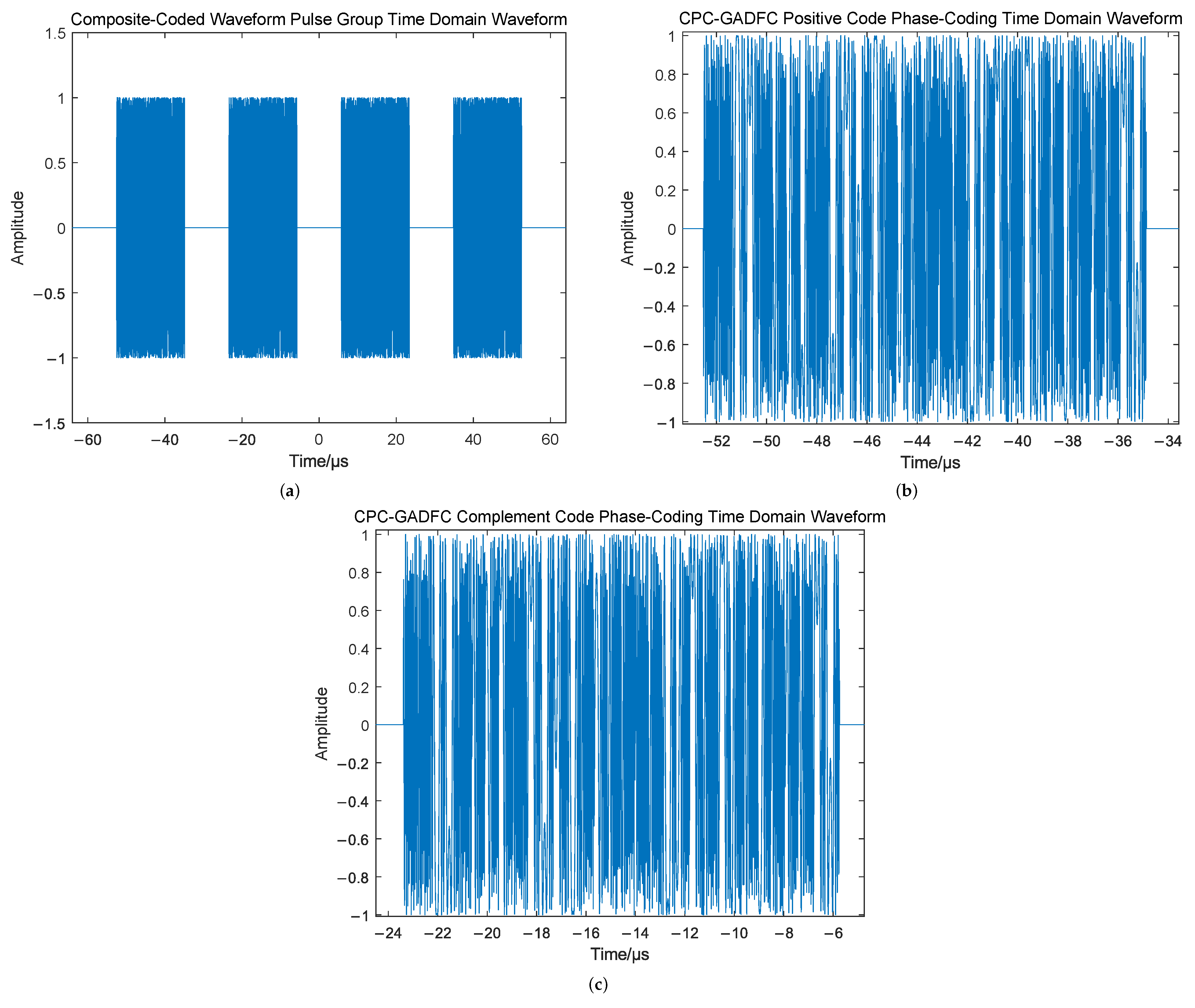
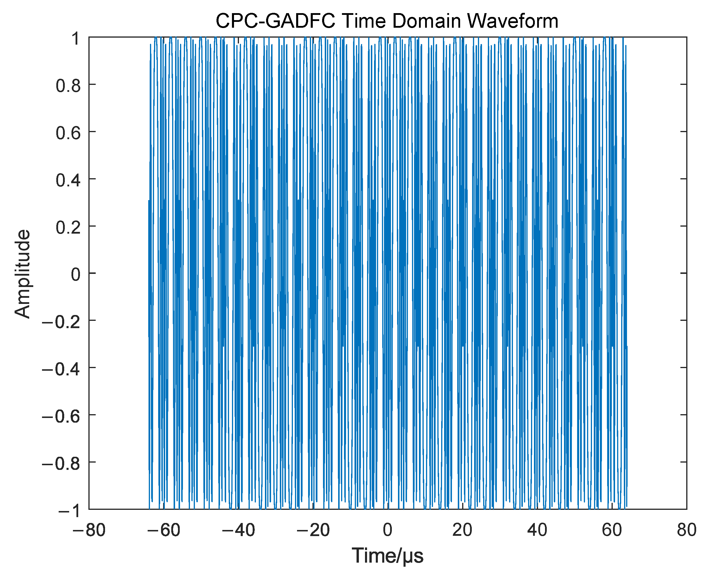
3.1. Joint Coding Waveform Expression

Based on the LFM waveform, GADFC is performed on the waveform. The time domain expression of the waveform is given by:
s G A D F C ( t ) = 1 m T L F M r e c t t T L F M e j π k t 2 e j 2 π f ( m ) t ,
where f ( m ) = c G A D F C · Δ f is the frequency modulation of the waveform for the GADFC encoding sequence (the number of codewords in the coding sequence is m = 32 ), and Δ f are the frequency intervals.
It can be seen that the GADFC’s envelope is similar to the LFM waveform ( u G A D F C ( t ) = u L F M ( t ) ). Since the pulse width of the basic LFM waveform is T L F M , its time-bandwidth product is k T L F M 2 . After the frequency-coding, the width of each pulse in the pulse group is T G A D F C = m · T L F M . At this time, the time-bandwidth product of the radar waveform is m T G A D F C = m 2 k T L F M 2 . It can be seen that the frequency code modulation of LFM can increase the time-bandwidth product of the waveform, which is m 2 times that of the LFM waveform. In addition, a larger time-bandwidth product waveform leads to a better LPI performance.
Based on s G A D F C ( t ) , the intra-pulse joint phase-coding is synchronously performed. In the joint phase-coding for s G A D F C ( t ) , it is assumed that the period of the radar transmission signal is P c o m p . Since the phase-coding is similar to the frequency-coding, and the LFM waveform having a pulse length of T L F M is also encoding, the joint coding pulse width T c o m p should be equal to the GADFC pulse width T G A D F C , that is, T c o m p = T G A D F C = m · T L F M . Since CPC is composed of positive code and complement code, the envelope of the CPC waveform can be expressed as:
u C P C A ( t ) = 1 P c o m p m = 1 P c A ( m ) δ ( t m T L F M ) , 0 < t < P c o m p T L F M 0 , o t h e r s ,
u C P C B ( t ) = 1 P c o m p m = 1 P c B ( m ) δ ( t m T L F M ) , 0 < t < P c o m p T L F M 0 , o t h e r s ,
where u C P C A ( t ) and u C P C B ( t ) are respectively the positive code envelope and complement code envelope in the complementary code sequence, c A ( m ) and c B ( m ) are respectively the positive code and complement code sequence, and is the length which is similar to that of the GADFC codes sequence.
At this point, the complex envelope of the joint coding waveform can be expressed as:
u c o m p A ( t ) = 1 P c o m p m T L F M m = 1 P c A ( m ) r e c t t m T L F M T L F M e j π k ( t k T L F M ) 2 , 0 < t < P c o m p T L F M 0 , o t h e r s ,
u c o m p B ( t ) = 1 P c o m p m T L F M m = 1 P c B ( m ) r e c t t m T L F M T L F M e j π k ( t k T L F M ) 2 , 0 < t < P c o m p T L F M 0 , o t h e r s .
Equations (10) and (11) show that the envelope form of the joint coding waveform is the convolution of u G A D F C ( t ) and u C P C ( t ) , which can be expressed as:
u ( t ) = u G A D F C ( t ) u C P C A ( t ) u G A D F C ( t ) u C P C B ( t ) ,
where ⊗ represents the convolution operation.
Therefore, the time-domain expression of the CPC-GADFC joint coding waveform based on LFM, is given by:
s c o m p ( t ) = 1 P c o m p m T L F M m = 1 P c A ( m ) r e c t t m T L F M T L F M e j π k ( t m T L F M ) 2 e j 2 π f ( m ) t 1 P c o m p m T L F M m = 1 P c B ( m ) r e c t t m T L F M T L F M e j π k ( t m T L F M ) 2 e j 2 π f ( m ) t .
Figure 3 and Equation (13) show the radar transmitted waveform and time-frequency distribution of Figure 4 and Figure 5.
Figure 4 shows that each pulse in a pulse group is alternately transmitted with the positive code and complement code of the CPC (cf. Figure 4b,c). Transmitting alternately aims at reducing the influence of the fluctuation of echo ability caused by the angular scintillation of the effective reflection area of the target. It can be seen from Figure 5 that, since the GADFC coding sequence performed by each pulse is the same within a pulse group, the time-frequency distribution between the pulses is also the same. The design flow of the LFM-based CPC-GADFC joint modulation radar waveform is shown in Figure 6.
According to the Fourier transform properties, the spectrum of the combined signal is the product of the LFM-GADFC waveform and the CPC waveform spectrum:
U c o m p ( f ) = U G A D F C ( f ) · U C P C A ( f ) U G A D F C ( f ) · U C P C B ( f ) ,
where U c o m p ( f ) , U G A D F C ( f ) , U C P C A ( f ) and U C P C B ( f ) are the spectral expressions of the joint code waveform, GADFC code waveform, CPC positive code and complement code waveform, respectively.
Due to the fact that in the frequency-phase-coding process based on the LFM waveform, the basic shape of the signal will not be changed by the phase-coding process, the factor affecting the frequency spectrum is the frequency-coding one. The frequency spectrum of the single pulse of the joint coding waveform is shown in Figure 7.
It can be seen from Figure 7 that the LFM-CPC waveform can still maintain the basic form of the LFM waveform spectrum after phase-coding. However, the new joint coding waveform spectrum after CPC-GADFC joint coding, loses the basic form of the LFM waveform. When the interceptor receives the radar transmission waveform, it is not easy to accumulate for a long time. It is easier to consider noise, which improves the radar LPI performance.

3.2. Performance Analysis and Processing Method Design

Section 3.1 introduced the joint coding waveform’s design process and time-frequency domain expression. In Section 3.2, the ambiguity function analysis, LPI characteristic analysis, algorithm complexity analysis and signal processing flow of the joint coding waveform, are introduced.

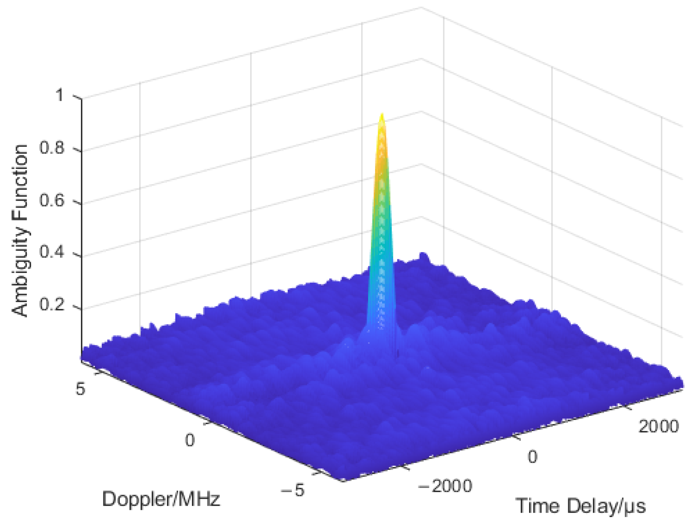
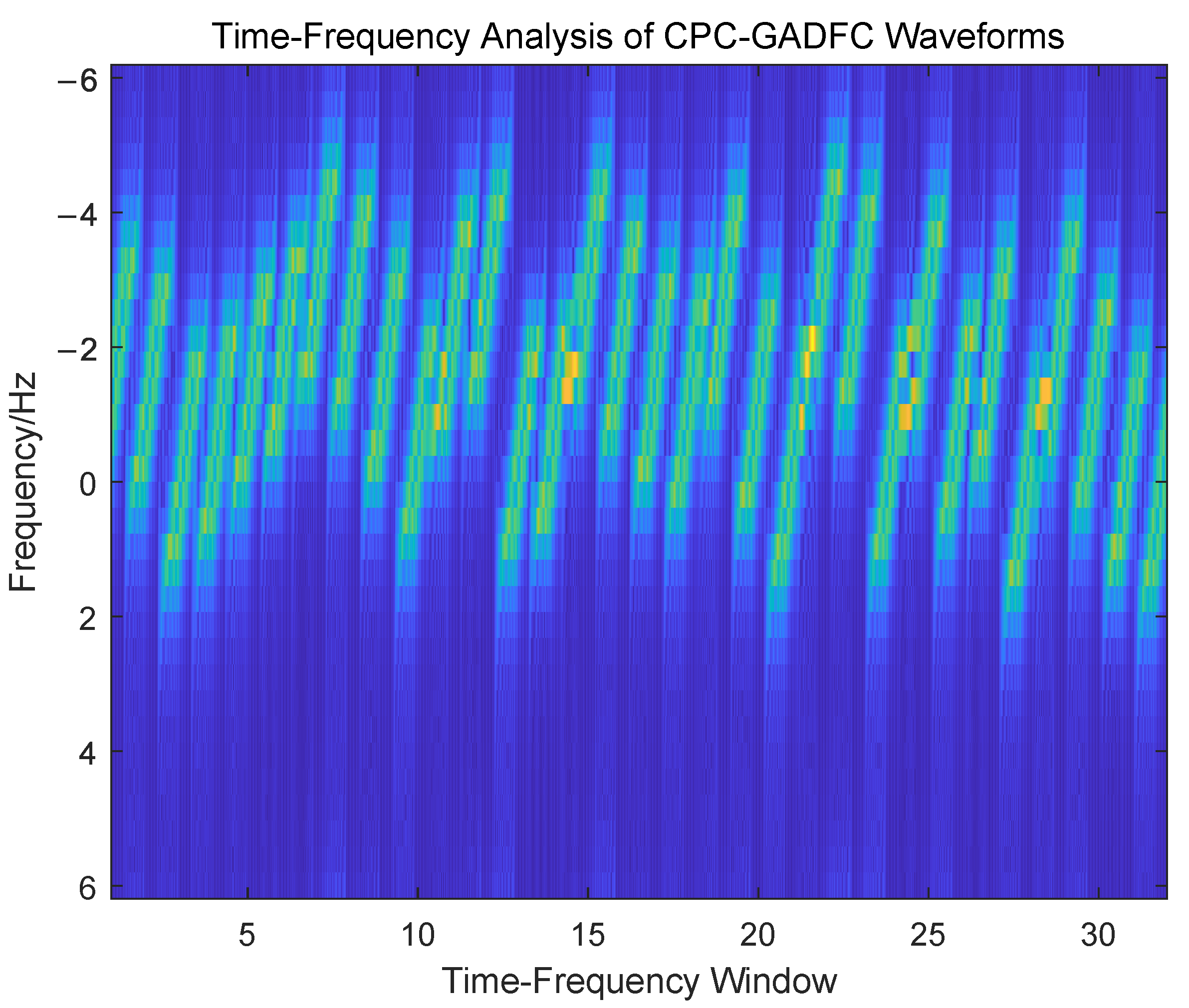
3.2.1. Ambiguity Function Analysis

Because the LFM-based CPC-GADFC joint coding waveform uses complementary phase-coding sequences, it has two sequences of positive code and complement code. Therefore, according to the definition of ambiguity function, the ambiguity function of the joint coding waveform also consists of two parts:
χ c o m p A ( τ , f d ) = s c o m p A ( t ) s c o m p A ( t + τ ) e j 2 π f d t d t ,
χ c o m p B ( τ , f d ) = s c o m p B ( t ) s c o m p B ( t + τ ) e j 2 π f d t d t .
By substituting Equations (15) and (16) into Equations (10) and (11), the following is obtained:
s c o m p A ( t ) = 1 P c o m p m T L F M m = 1 P c A ( m ) r e c t t m T L F M T L F M e j π k ( t m T L F M ) 2 e j 2 π f ( m ) t = r e c t 1 T L F M 1 P c o m p m T L F M m = 1 P c A ( m ) δ t m T L F M T L F M e j π k ( t m T L F M ) 2 e j 2 π f ( m ) t = s 1 ( t ) s 2 ( t ) ,
s c o m p B ( t ) = 1 P c o m p m T L F M m = 1 P c B ( m ) r e c t t m T L F M T L F M e j π k ( t m T L F M ) 2 e j 2 π f ( m ) t = r e c t 1 T L F M 1 P c o m p m T L F M m = 1 P c B ( m ) δ t m T L F M T L F M e j π k ( t m T L F M ) 2 e j 2 π f ( m ) t = s 1 ( t ) s 3 ( t ) .
Equations (17) and (18) show that the time-domain expression of the joint coding waveform can be rewritten as the form of window function and signal impulse convolution. For s c o m p A ( t ) , Equation (15) has:
χ c o m p A ( τ , f d ) = s c o m p A ( t ) s c o m p A ( t + τ ) e j 2 π f d t d t = s c o m p A ( t ) e j 2 π f d t s c o m p A ( τ ( t ) ) d t = s c o m p A ( τ ) e j 2 π f d t s c o m p A ( τ ) .
According to Equation (17), Equation (19) can be further rewritten as:
χ c o m p A ( τ , f d ) = s 1 ( τ ) s 2 ( τ ) e j 2 π f d t s 1 ( τ ) s 2 ( τ ) = s 1 ( τ ) e j 2 π f d t s 2 ( τ ) e j 2 π f d t s 1 ( τ ) s 2 ( τ ) = s 1 ( τ ) e j 2 π f d t s 1 ( τ ) s 2 ( τ ) e j 2 π f d t s 2 ( τ ) = χ 1 ( τ , f d ) χ 2 ( τ , f d ) .
According to Equation (18), the ambiguity function of the complementary phase-coding joint waveform s c o m p B ( t ) can be expressed as:
χ c o m p B ( τ , f d ) = s 1 ( τ ) s 3 ( τ ) e j 2 π f d t s 1 ( τ ) s 3 ( τ ) = s 1 ( τ ) e j 2 π f d t s 3 ( τ ) e j 2 π f d t s 1 ( τ ) s 3 ( τ ) = s 1 ( τ ) e j 2 π f d t s 1 ( τ ) s 3 ( τ ) e j 2 π f d t s 3 ( τ ) = χ 1 ( τ , f d ) χ 3 ( τ , f d ) .
It can be deduced from this equation derivation that the ambiguity function of the CPC-GADFC joint coding waveform based on LFM, is composed of two parts. Each part is composed of the convolution superposition of two ambiguity functions. According to the autocorrelation property and the ambiguity function expression of complementary code, the autocorrelation characteristics can be obtained using complementary code for the phase-coding. Moreover, the influence of the range-Doppler coupling on the signal is reduced. The ambiguity function graph of the joint coding waveform is shown in Figure 8.
It can be seen from Figure 8 that the ambiguity function of the LFM-based CPC-GADFC joint coding waveform presents a good “pushpin” shape. Based on the high Doppler tolerance of the LFM signal, the joint coding waveform reduces the Doppler range coupling. It has a high range and velocity resolution, as well as low sidelobe characteristics, which improves the radar’s ability to detect targets. Complex waveforms have high modulation complexity, and the phase-frequency joint coding increases the difficulty of demodulation and accumulation of radar waveforms by interceptors. For the wideband interception receivers, the intra-pulse phase-frequency agility can make the radar waveform spectral form similar to the noise frequency. This makes the waveform submerged in the noise and challenging to capture. Due to the complex phase-frequency hopping rules and moderate hopping performance for narrowband receivers, the joint coding waveform significantly improves the LPI performance of the radar system.

3.2.2. Lpi Characteristic Analysis

In order to quantitatively analyze the LPI of the joint coding radar, the perspective of the Schleher interception factor can first be used:
α = R i R r ,
where α is the interception factor, R i is the maximum distance of the interception receiver, and R r is the maximum action distance of the radar detection.
When the radar parameter settings are the same and the parameter settings of the interception receiver are certain, the interception factor can be simplified and expressed in the form of time-bandwidth product:
α = c · 1 B T .
When the radar uses LFM as the transmitting waveform, since its time-bandwidth product is B T L F M 2 , the radar interception factor is given by:
α L F M = c · 1 B T L F M 2 .
If the radar uses the LFM-based CPC-GADFC joint coding waveform as the transmit waveform, since the phase-coding and the frequency-coding simultaneously encode the intra-pulse LFM waveform, the impact on the waveform time-bandwidth product is consistent, which is m 2 B T L F M 2 . The interception factor of the radar is: if the radar uses the LFM-based CPC-GADFC joint coding waveform as the transmit waveform, since the phase-coding and the frequency-coding processes simultaneously code the intra-pulse LFM waveform, the impact on the waveform time-bandwidth product ( m 2 B T L F M 2 ) is consistent. The interception factor of the radar is given by:
α c o m p = c · 1 m 2 B T L F M 2 .
By comparing Equations (24) and (25), it can be seen that the joint coding waveform has a larger time-bandwidth product, which is m 2 times that of the LFM waveform, and α c o m p < < α L F M , while the joint coding waveform has a better LPI performance.

3.2.3. Analysis of the Algorithm Complexity

The complexity of the radar waveform can reflect the used modulation mode, and the complexity characteristics of the waveform are less affected by the signal-to-noise ratio. Therefore, the sparsity of the waveform frequency domain can be used to express the complexity [30,31]. In the frequency domain of waveform normalization, a window function having a length of N 0 is constructed to slide from left to right in the frequency domain waveform sequence G N . The number of element 1 in the i-th window is M i . The average coefficient in the window can be expressed as:
μ = 1 N / N 0 i = 1 N / N 0 D i , i = 1 , 2 , , N / N 0 ,
where N is the frequency domain waveform length, and D i is given by:
D i = M i M i N / N 0 , i = 1 , 2 , , N / N 0 ,
where M is the total number of 1 element in the frequency domain waveform.
It can be seen that compared with the traditional radar LFM waveform, the CPC-GADFC waveform carries out phase and frequency joint coding in the pulse. As shown in the spectrum of the single pulse of the joint coding waveform in Figure 7, the sparse complexity of the CPC-GADFC frequency domain is higher than that of the LFM waveform.
The time complexity of the CPC-GADFC waveform is higher than those of the LFM waveform and DFC waveform. This is due to the fact that the CPC-GADFC waveform is simultaneously coded with phase and frequency, and GA is used for DFC codeword optimization. In addition, compared with the CPC waveform, the CPC-GADFC waveform has optimized frequency-coding on the basis of the CPC waveform. Therefore, the time complexity of the CPC-GADFC is higher. The complex radar waveform can increase the accumulation and deciphering difficulty of the interceptor, and significantly improve the LPI performance of the radar.

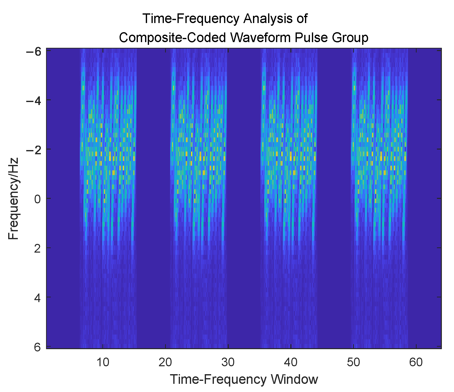
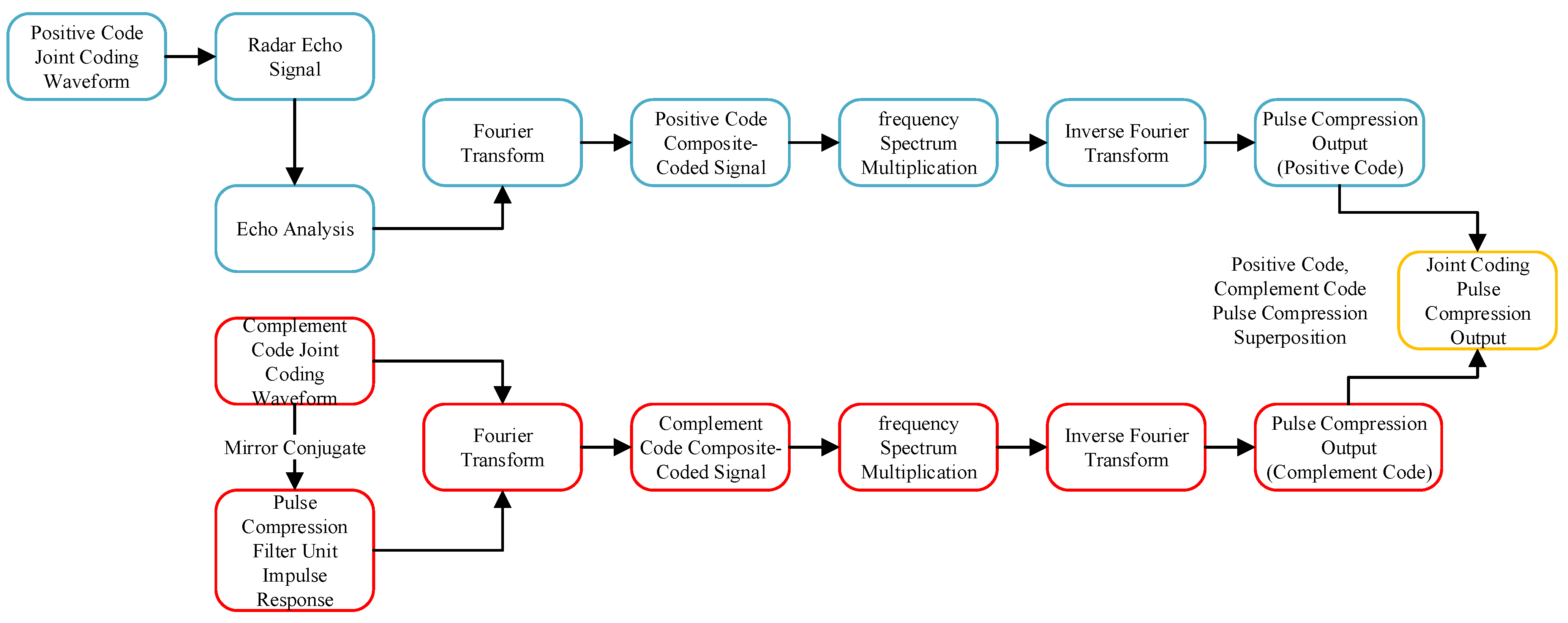
3.2.4. Signal Processing Flow

Because the joint coding waveform uses a complementary code sequence in phase modulation, the waveform in the pulse group is alternately transmitted with phase-coding positive code and complementary code in the transmission process. The two coding waveforms should be processed together in echo processing. When an echo is received, the positive code and the complement code are first used as a priori to analyze the correlation coefficient of the echo. This step aims at determining the type of echo phase-coding, which is convenient for subsequent analysis. Assuming that the echo received at the current moment is a joint coding waveform encoding with positive code when performing pulse compression, the two-phase codes should be subjected to matched filtering. The results are simultaneously superimposed. This process is referred to as joint coding echo pulse compression processing.
The echo pulse compression processing of modern radar mainly uses digital signal processing. Two approaches exist for performing it. The time-domain correlation processing method is often used when the demand is a small pulse pressure ratio. When a large pulse pressure ratio is required, it is usually performed in the frequency domain by Fourier transform. Since the matched filter is a linear time-invariant system, it can be determined from the nature of Fourier change:
F F T h c o m p A ( t ) s c o m p A ( t + τ ) = H c o m p A ( f ) · S c o m p A ( f ) ,
F F T h c o m p B ( t ) s c o m p B ( t + τ ) = H c o m p B ( f ) · S c o m p B ( f ) ,
where τ is the echo delay expressed as τ = 2 R / c , R is the distance from the radar to the target, c is the speed of light, h c o m p A ( t ) and h c o m p B ( t ) are used as the matched filter reference signals of radar echoes that are respected, s c o m p A ( t ) and s c o m p B ( t ) are inverse conjugate shock functions expressed as:
h c o m p A ( t ) = s c o m p A * ( t ) , h c o m p B ( t ) = s c o m p B * ( t ) .
When both signals are correctly sampled, the matched filter output signal of the positive and complement phase joint coding signal can be expressed as:
s m f A ( t ) = I F F T H c o m p A ( f ) · S c o m p A ( f ) , s m f B ( t ) = I F F T H c o m p B ( f ) · S c o m p B ( f ) .
Finally, the matched filter requires to superimpose the s m f A ( t ) and s m f B ( t ) , in order to obtain the pulse compression results of the CPC-GADFC joint coding waveform based on LFM. The specific process is shown in Figure 9.
It can be seen from Figure 9 that the pulse compression of the LFM-based CPC-GADFC joint coding waveform consists of a matched filter by the positive phase and the complement phase, respectively. The results are then superimposed to obtain the joint coding waveform pulse compression output. The advantage of the alternately transmitted process is that the low sidelobe level of the complementary code autocorrelation can be used to obtain a pulse compression result with low sidelobe characteristics, in order to achieve a better target detection performance.

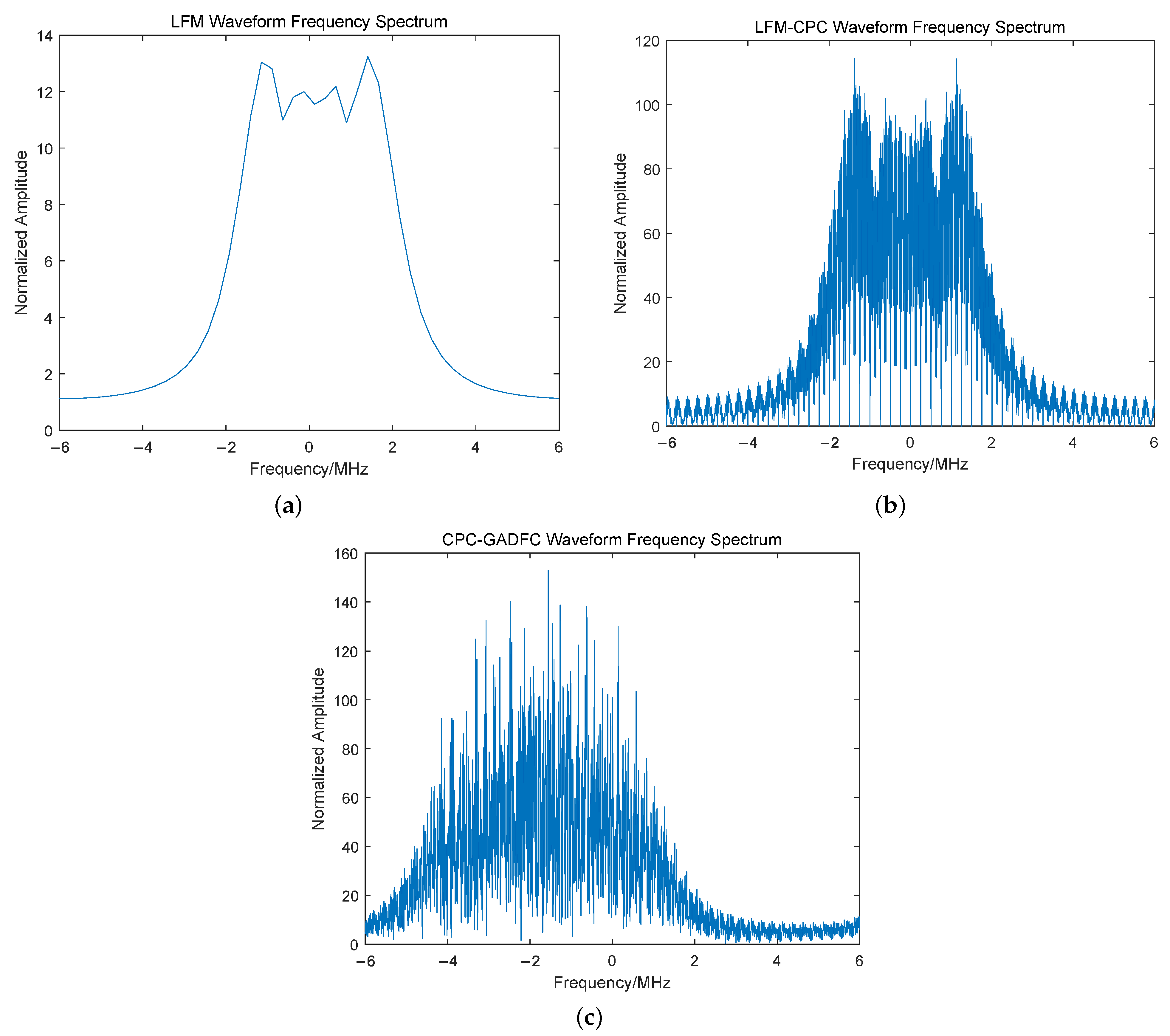
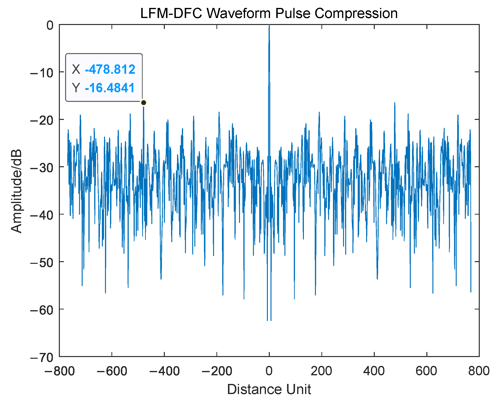
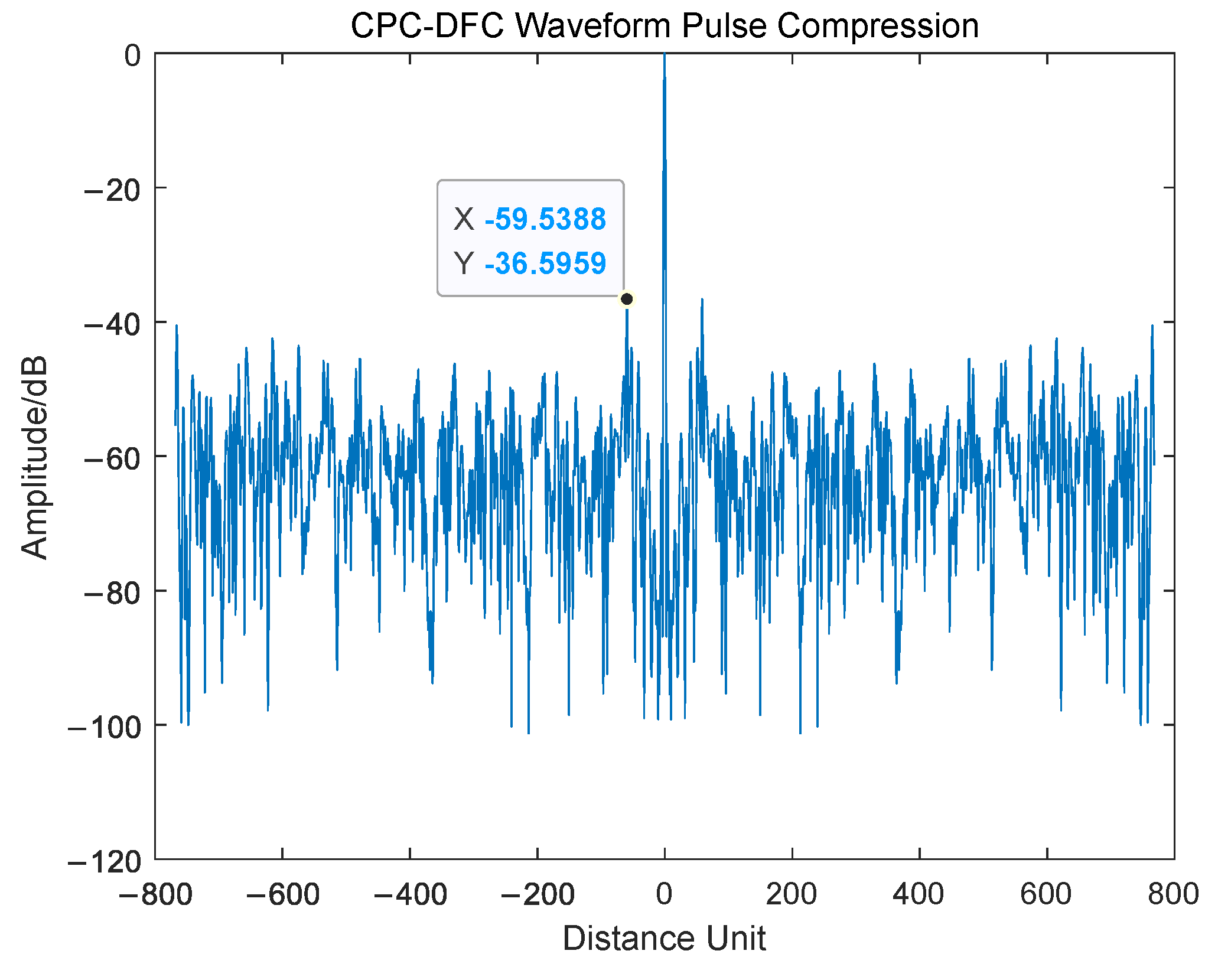
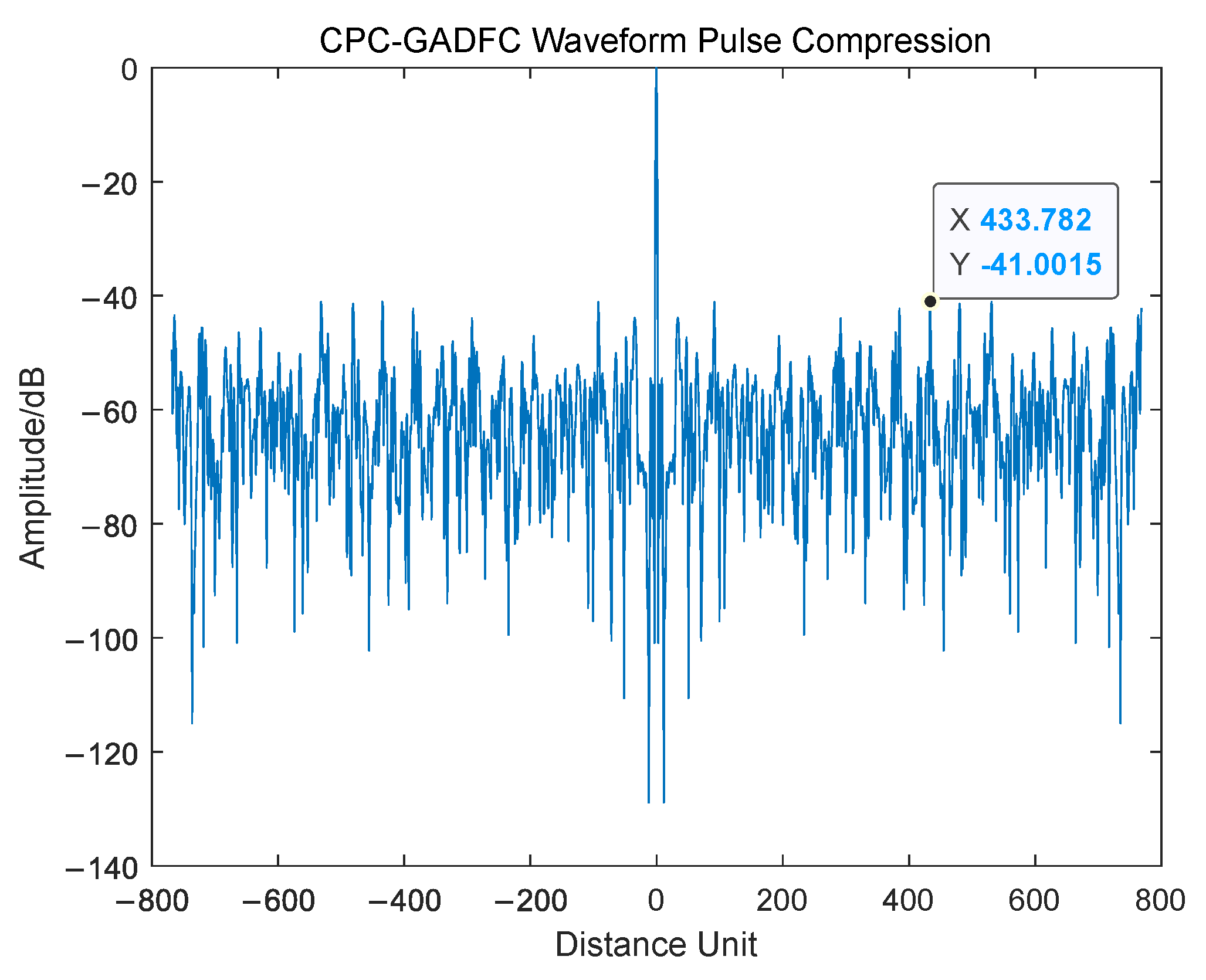
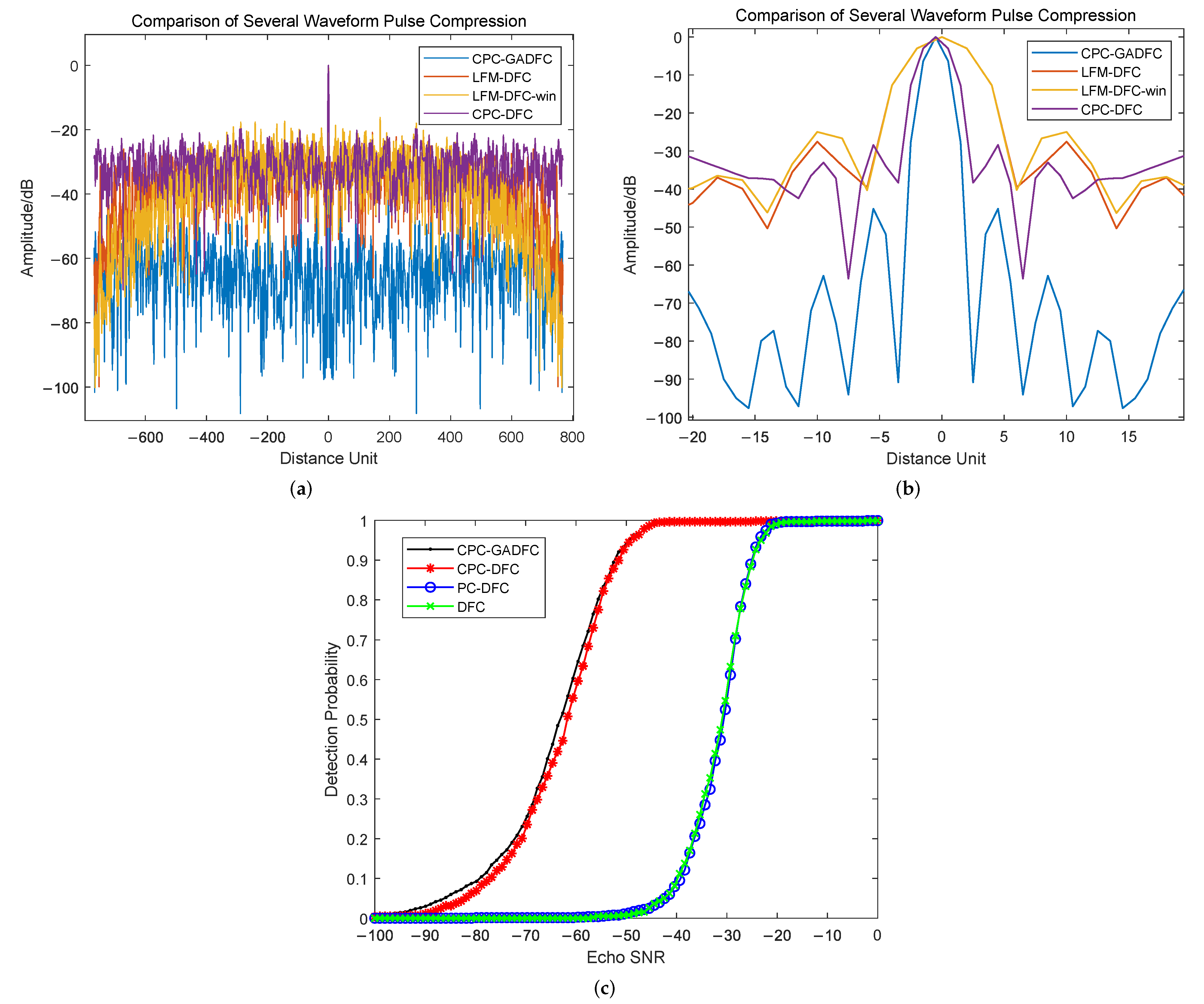
4. Result and Discussion

In order to verify the robustness of the LFM-based CPC-GADFC joint coding waveform, the experiment performs a time-frequency analysis of the waveform from the perspective of a pulse waveform. Pulse compression is performed on the echo, and the obtained result is compared with the LFM waveform and CPC-DFC joint coding waveform. Finally, the target detection performance of the joint coding waveform is analyzed. In this paper, the complementary code sequence, DFC sequence and GADFC sequence are all of 32 bits. Their codewords are shown in Table 2.
In one transmission pulse, the time domain waveform and time-frequency analysis of the CPC-GADFC joint coding waveform based on LFM, are shown in Figure 10 and Figure 11.
It can be seen from Figure 10 that the complementary code sequence efficiently encodes the LFM, and the purpose of increasing the time-bandwidth product is achieved by changing the phase structure of the signal. Moreover, it can be observed from Figure 11 that GADFC changes the frequency distribution of the LFM waveform, and simultaneously performs frequency-coding based on phase-coding intra-pulse, which increases the complexity of the joint coding waveform.
In order to verify the performance of the designed waveform, the echo pulse compression results of the LFM-DFC waveform, CPC-DFC waveform and CPC-GADFC waveform are compared (cf. Figure 12, Figure 13 and Figure 14).
It can be seen from Figure 12, Figure 13 and Figure 14 that the CPC-GADFC joint coding waveform uses the complementary code for phase-coding, which can significantly reduce the sidelobe through the characteristics of the autocorrelation and sidelobe cancellation of the complementary code. Compared with DFC, the joint coding GADFC can find the optimal distance between each codeword in DFC encoding by GA, which increases the orthogonality between the codewords. After coding, the maximum main side ratio can be reduced by 3.5 dB, compared with the unoptimized joint coding waveform. The joint coding waveform has the characteristics of ultra-low sidelobes, and the distribution of side lobes is more uniform. The jointly coding waveform improves the LPI performance of the signal while improving the radar’s ability to detect targets, as shown in Figure 15.
It can be seen from Figure 15 that the pulse compression sidelobe level of CPC-GADFC waveform is significantly lower than that of other waveforms and lower than that of the DFC waveform with Hamming window. It can also be seen that the pulse compression main lobe of the CPC-GADFC waveform is significantly narrower than other waveforms, which indicates that the waveform designed in this paper can concentrate the radar energy and have more accurate target detection performance. Moreover, it can be observed that the detection probability of the CPC-GADFC waveform is much higher than that of the DFC and PC-DFC waveform, and the detection probability of the CPC-GADFC waveform is higher than that of the CPC-DFC waveform.

5. Conclusions

This paper proposes a CPC-GADFC joint coding holographic RF stealth radar waveform, based on the LFM waveform. The time-frequency domain and ambiguity function expressions of the joint coding waveform are derived. The LPI characteristic of the joint coding waveform is derived by the interception factor. In addition, the complexity of the algorithm is analyzed. Finally, a matched filter is designed for the joint coding waveform in order to achieve echo pulse compression. The experiments show that the CPC-GADFC joint coding waveform has the advantages of phase-coding waveform and frequency-coding waveform. This large time-bandwidth product waveform has better LPI and low sidelobe characteristics. Similarly, the CPC-GADFC joint coding waveform has better target detection performance and higher practical value.

Author Contributions

Conceptualization, Y.S., B.T. and S.X.; methodology, Y.S. and B.T.; software, Y.S. and Y.W.; validation, Y.S., J.X., Y.Y. and B.T.; formal analysis, Y.S.; investigation, Y.S.; resources, Y.S. and B.T.; data curation, Y.S.; writing—original draft preparation, Y.S., J.X. and B.T.; writing—review and editing, Y.S.; visualization, Y.S.; supervision, B.T. and S.X.; project administration, B.T. and S.X.; funding acquisition, B.T. and S.X. All authors have read and agreed to the published version of the manuscript.

Funding

This work was supported in part by Fundamental Research Funds for the Central Universities, Sun Yat-sen University (No. 22lgqb15), Shenzhen Fundamental Research Program (No. JCYJ20180307151430655), Shenzhen Science and Technology Program (No. KQTD20190929172704911), Shenzhen Science and Technology Program (No. GXWD20201231165807008), Hunan Provincial Natural Science Foundation of China (No. 2021JJ20056), Foundation of Pinghu Laboratory (No. 20220362).

Data Availability Statement

Not applicable.

Acknowledgments

The authors acknowledge the funding, equipment and technical support provided by the School of Electronics and Communication Engineering of Sun Yat-sen University.

Conflicts of Interest

The authors declare no conflict of interest.

Abbreviations

The following abbreviations are used in this paper:
LPILow Probability of Intercept
UWBUltra-Wide Band
LFMLinear Frequency Modulation
FSKFrequency Shift Keying
PSKPhase Shift Keying
CPCComplementary Phase-Coding
DFCDiscrete Frequency-Coding
GAGenetic Algorithm
GADFCDiscrete Frequency-Coding Optimized by Genetic Algorithm

References

  1. Giubbolini, L. A multistatic microwave radar sensor for short range anticollision warning. IEEE Trans. Veh. Technol. 2000, 49, 2270–2275. [Google Scholar] [CrossRef]
  2. Ahmed, A.; Zhang, Y.D.; Hassanien, A. Joint Radar-Communications Exploiting Optimized OFDM Waveforms. Remote. Sens. 2021, 13, 4376. [Google Scholar] [CrossRef]
  3. Shi, C.; Wang, F.; Zhou, J.; Chen, J. Adaptive radar jamming waveform design based on low probability of intercept. In Proceedings of the 2015 IEEE China Summit and International Conference on Signal and Information Processing (ChinaSIP), Chengdu, China, 12–15 July 2015; pp. 1017–1021. [Google Scholar]
  4. Wang, W.Q. Moving-Target Tracking by Cognitive RF Stealth Radar Using Frequency Diverse Array Antenna. IEEE T. Geosci. Remote 2016, 54, 3764–3773. [Google Scholar] [CrossRef]
  5. Hejazikookamari, F.; Norouzi, Y.; Kashani, E.S.; Nayebi, M.M. A Novel Method to Detect and Localize LPI Radars. IEEE Trans. Signal Process. 2019, 55, 2327–2336. [Google Scholar] [CrossRef]
  6. Kamble, J.; Pasha, I.A.; Madhavilatha, M. Design of HRR detection system for measurement of RF signal power. In Proceedings of the 2016 10th International Conference on Intelligent Systems and Control (ISCO), Coimbatore, India, 7–8 January 2016; pp. 1–5. [Google Scholar]
  7. Guey, J.C.; Bell, M.R. Diversity waveform sets for delay-Doppler imaging. IEEE Trans. Inf. Theory 1998, 44, 1504–1522. [Google Scholar] [CrossRef]
  8. Abd, M.H.; Al-Suhail, G.A.; Tahir, F.R.; Ali Ali, A.M.; Abbood, H.A.; Dashtipour, K.; Jamal, S.S.; Ahmad, J. Synchronization of Monostatic Radar Using a Time-Delayed Chaos-Based FM Waveform. Remote. Sens. 2022, 14, 1984. [Google Scholar] [CrossRef]
  9. Hongbo, S.; Yilong, L.; Guosui, L. Ultra-wideband technology and random signal radar: An ideal combination. IEEE Aero. El. Sys. Mag. 2003, 18, 3–7. [Google Scholar] [CrossRef]
  10. De Witte, E.; Griffiths, H.D. Improved Waveforms for Satellite-Borne Precipitation Radar; IET Digital Library: London, UK, 2011. [Google Scholar]
  11. Dietl, G.; Wang, J.; Ding, P.; Zoltowski, M.D.; Love, D.J.; Utschick, W. Hybrid transmit waveform design based on beam-forming and orthogonal space-time block coding. In Proceedings of the (ICASSP ’05) IEEE International Conference on Acoustics, Speech, and Signal Processing, Philadelphia, PA, USA, 18–23 March 2005; pp. 893–896. [Google Scholar]
  12. Kassab, R.; Lesturgie, M.; Fiorina, J. Quasi-continuous waveform design for dynamic range reduction. Electron. Lett. 2008, 44, 646–647. [Google Scholar] [CrossRef] [Green Version]
  13. Geroleo, F.G.; Brandt-Pearce, M.; Brown, C.L. Detection and estimation of multi-pulse LFMCW radar signals. In Proceedings of the 2010 IEEE Radar Conference, Arlington, VA, USA, 10–14 May 2010; pp. 1009–1013. [Google Scholar]
  14. Zhang, Y.X.; Hong, R.J.; Pan, P.P.; Deng, Z.M.; Liu, Q.F. Frequency-Domain Range Sidelobe Correction in Stretch Processing for Wideband LFM Radars. IEEE Trans. Aerosp. Electron. Syst. 2017, 53, 111–121. [Google Scholar] [CrossRef]
  15. Bao, H.; Ziemann, A.; He, Z.S. Design and Measurements of MSK-LFM RadCom System. In Proceedings of the 2020 17th European Radar Conference (EuRAD), London, UK, 16–18 February 2021; pp. 9–12. [Google Scholar]
  16. Raghavendra, C.G.; Prajwal, B.R.; Sagar, G.D.; Keerthana, R.; Meghna, S.; Prasad, N.N.S.S.R.K. Reduction of Envelope Fluctuations in OFDM Radar Signals Using Coding Technique. In Proceedings of the 2018 International Conference on Communication and Signal Processing (ICCSP), Chennai, India, 3–5 April 2018; pp. 802–806. [Google Scholar]
  17. Li, Z.; Perera, S.; Zhang, Y.; Zhang, G.; Doviak, R. Phased-Array Radar System Simulator (PASIM): Development and Simulation Result Assessment. Remote. Sens. 2019, 11, 422. [Google Scholar] [CrossRef] [Green Version]
  18. Suh, J.; Lee, J.; Gil, G.T.; Hong, S. Time-and-Frequency Hybrid Multiplexing for Flexible Ambiguity Controls of DFT-coded MIMO OFDM Radar. IEEE Access 2021, 9, 137793–137808. [Google Scholar] [CrossRef]
  19. Park, B.; Ahn, J.M. Intra-pulse modulation recognition using pulse description words and complex waveforms. In Proceedings of the 2017 International Conference on Information and Communication Technology Convergence (ICTC), Jeju Island, Korea, 18–20 October 2017; pp. 555–560. [Google Scholar]
  20. Hou, J.; Tao, R.; Shan, T.; Qi, L. A novel LPI radar signal based on hyperbolic frequency hopping combined with Barker phase code. In Proceedings of the 7th International Conference on Signal Processing, Beijing, China, 31 August–4 September 2004; pp. 2070–2073. [Google Scholar]
  21. Saifullah, Y.; Yang, G.; Feng, X.U. A Four-leaf Clover-shaped Coding Metasurface For Ultra-wideband Diffusion-like Scattering. J. Radars 2021, 10, 382–390. [Google Scholar]
  22. Song, X. An Improved Algorithm for Pulse Compression of Taylor Four-phase Coding Signal and Its Simulation. Ship Electron. Eng. 2006, 06, 160–163. [Google Scholar]
  23. Chunhong, Y.; Zengli, L. The Superiority Analysis of Linear Frequency Modulation and Barker Code Composite Radar Signal. In Proceedings of the 2013 Ninth International Conference on Computational Intelligence and Security, Emeishan, China, 14–15 December 2013; pp. 182–184. [Google Scholar]
  24. Zhang, T.; Shuai, C.; Zhou, Y. Deep Learning for Robust Automatic Modulation Recognition Method for IoT Applications. IEEE Access 2020, 1, 117689–117697. [Google Scholar] [CrossRef]
  25. Agrawal, D.; Maheshwari, S. Design and implementation of current mode circuit for digital modulation. Integration 2021, 78, 118–123. [Google Scholar] [CrossRef]
  26. Kundu, N.K.; Mallik, R.K.; Mckay, M.R. Signal Design for Frequency-Phase Keying. IEEE Trans. Wirel. Commun. 2020, 1, 4067–4079. [Google Scholar] [CrossRef]
  27. Jahangir, M.; Baker, C.J.; Oswald, G.A. Doppler characteristics of micro-drones with L-Band multibeam staring radar. In Proceedings of the 2017 IEEE Radar Conference (RadarConf), Seattle, WA, USA, 8–12 May 2017; pp. 1052–1057. [Google Scholar]
  28. Golay, M. Complementary series. Information Theory. IRE Trans. 1961, 7, 82–87. [Google Scholar]
  29. Mott, M.H.; Roome, A.T.; Erickson, C.W. Signal Processing System Employing Reference-Signal Controlled-Integrator for Integrating Resultant of Two Summing-Circuits Having Complementary Inputs. U.S. Patent US3316492 A, 25 April 1967. [Google Scholar]
  30. Jing, X.U.; Ming-Hao, H.E.; Chen, C.X.; Zhou, L. Algorithm Complexity Analysis of Radar Emitter Characteristic Parameter Extraction. J. China Acad. Electron. Inf. Technol. 2013, 8, 43–47. [Google Scholar]
  31. Kang, B.; Rangaswamy, M. Radar Waveform Design Under Communication Sum Capacity Constraint. IEEE Trans. Signal Process. 2021, 69, 2795–2806. [Google Scholar] [CrossRef]
Figure 1. Complementary Code Autocorrelation Function.
Remotesensing 14 02592 g001
Figure 2. Pulse Alternate Transmission Mode.
Remotesensing 14 02592 g002
Figure 3. DFC Coding and GADFC Coding Autocorrelation Function Comparison.
Remotesensing 14 02592 g003
Figure 4. CPC-GADFC Joint Coding Radar Transmit Waveform, (a) a pulse group is alternately transmitted by positive code phase-coding and complementary code phase-coding, (b) the positive code phase-coding time domain waveform, (c) the complementary code phase-coding time domain waveform.
Remotesensing 14 02592 g004
Figure 5. Time-Frequency Analysis of Joint Coding Waveform.
Remotesensing 14 02592 g005
Figure 6. Design Process of CPC-GADFC Joint Coding Radar Waveform Based on LFM.
Remotesensing 14 02592 g006
Figure 7. Spectrum comparison of waveform single pulse, (a) the LFM waveform spectrum, (b) the LFM-CPC waveform spectrum, (c) the CPC-GADFC waveform spectrum.
Remotesensing 14 02592 g007
Figure 8. Ambiguity Function of the Joint coding Waveform.
Remotesensing 14 02592 g008
Figure 9. Pulse Compression Model of Joint coding Waveform Based on LFM.
Remotesensing 14 02592 g009
Figure 10. CPC -GADFC Time Domain Waveform.
Remotesensing 14 02592 g010
Figure 11. Time -Frequency Analysis of CPC-GADFC Waveform.
Remotesensing 14 02592 g011
Figure 12. LFM -DFC Waveform Pulse Compression.
Remotesensing 14 02592 g012
Figure 13. CPC -DFC Waveform Pulse Compression.
Remotesensing 14 02592 g013
Figure 14. CPC -GADFC Waveform Pulse Compression.
Remotesensing 14 02592 g014
Figure 15. Comparison Diagram of Several Waveform Pulse Compressions and Target Detection Probabilities, (a) comparison of the waveform pulse compression, (b) enlarged view of the main lobe position of the waveform pulse compression, and (c) comparison of the waveform target detection performance. Note that “win” denotes the Hamming window.
Remotesensing 14 02592 g015
Table 1. Correlation Coefficient Between Adjacent Transmitted Pulses.
Radar WaveformCorrel. Coeff.
DFC Waveform0.558
GADFC Waveform0.164
Table 2. Complementary Code, DFC Sequence and GADFC Sequence Codewords.
Coding ModeCodewords
Positive Code1, 1, 1, 1, 1, −1, 1, −1, −1, −1, 1, 1, 1, −1, −1, 1, 1, 1, −1, −1, 1, −1, −1, 1, −1, −1, −1, −1, 1, −1, 1, −1
Complement Code−1, −1, −1, −1, −1, 1, −1, 1, 1, 1, −1, −1, −1, 1, 1, −1, 1, 1, −1, −1, 1, −1, −1, 1, −1, −1, −1, −1, 1, −1, 1, −1
DFC12, 13, 25, 15, 6, 10, 19, 9, 18, 16, 5, 22, 7, 30, 32, 1, 11, 24, 27, 17, 14, 31, 2, 4, 3, 20, 29, 23, 8, 21, 28, 26
GADFC31.5455, 31.5152, 10.9091, 20.5455, 28, 9.2424, 31.9091, 5.9394, 20.4848, 10.6364, 18.7273, 17.7273, 9, 17.6667, 17.3939, 6, 12.3939, 11.2121, 5, 4.8788, 4.5152, 3.1212, 9.7576, 7.0606, 18.0303, 5.2424, 7.6364, 4.9394, 12.0606, 28.8181, 16.9394, 31.3636
Publisher’s Note: MDPI stays neutral with regard to jurisdictional claims in published maps and institutional affiliations.

