Technical Note

CO2 Injection Deformation Monitoring Based on UAV and InSAR Technology: A Case Study of Shizhuang Town, Shanxi Province, China

1
Key Laboratory of Digital Earth Science, Aerospace Information Research Institute, Chinese Academy of Sciences, Beijing 100094, China
2
University of Chinese Academy of Sciences, Beijing 100049, China
3
School of Geosciences & Surveying Engineering, China University of Mining and Technology, Beijing 100083, China
*
Author to whom correspondence should be addressed.
Remote Sens. 2022, 14(1), 237; https://doi.org/10.3390/rs14010237
Submission received: 13 December 2021 / Revised: 30 December 2021 / Accepted: 4 January 2022 / Published: 5 January 2022
(This article belongs to the Section Environmental Remote Sensing)

Abstract

:
Carbon Capture, Utilization and Storage, also referred to as Carbon Capture, Utilization and Sequestration (CCUS), is one of the novel climate mitigation technologies by which CO2 emissions are captured from sources, such as fossil power generation and industrial processes, and further either reused or stored with more attention being paid on the utilization of captured CO2. In the whole CCUS process, the dominant migration pathway of CO2 after being injected underground becomes very important information to judge the possible storage status as well as one of the essential references for evaluating possible environmental affects. Interferometric Synthetic Aperture Radar (InSAR) technology, with its advantages of extensive coverage in surface deformation monitoring and all-weather traceability of the injection processes, has become one of the promising technologies frequently adopted in worldwide CCUS projects. In this study, taking the CCUS sequestration area in Shizhuang Town, Shanxi Province, China, as an example, unmanned aerial vehicle (UAV) photography measurement technology with a 3D surface model at a resolution of 5.3 cm was applied to extract the high-resolution digital elevation model (DEM) of the study site in coordination with InSAR technology to more clearly display the results of surface deformation monitoring of the CO2 injection area. A 2 km surface heaving dynamic processes before and after injection from June 2020 to July 2021 was obtained, and a CO2 migration pathway northeastward was observed, which was rather consistent with the monitoring results by logging and micro-seismic studies. Additionally, an integrated monitoring scheme, which will be the trend of monitoring in the future, is proposed in the discussion.

1. Introduction

According to the IPCC Sixth Assessment Report, a general consensus concluded that human activities cause climate change, and 1.5 °C global warming will become an inevitable fact [1]. This is supported by the fact that in 2019 atmospheric concentrations of carbon dioxide (CO2) reached its peak value within at least 2 million years, and concentrations of other two key greenhouse gases (GHG), methane (CH4) and nitrous oxide (N2O), were also at their highest in at least 800,000 years. With the continuous rise of these green-house gases, a potential risk that climate tipping points will be breached with devastating consequences, including the collapse of ice sheets [2], abrupt changes in ocean circulation [3], complex extreme weather events [4] and far greater global warming than projected [5,6,7].
Carbon Capture, Utilization and Storage (CCUS) is considered to be the only technology that can reduce greenhouse gas emissions on an industrial scale at present [8], and CCUS-Enhanced Coalbed Methane Recovery (CCUS-ECBM) is a typical application in the coal field [9,10]. After the highly volatile liquid CO2 is injected into the coal seam, the volume of CO2 rapidly expands hundreds of times after gasification between the coal seams, which results in the pressure-sealed coalbed methane reservoir overcoming the flow resistance in the low permeability coal seam, effectively increasing the driving force of coalbed methane flow to the wellbore, and speeding up the effective production of coalbed methane [11]. At the same time, CO2 has a high adsorption, and coal seam will gradually absorb it. A large amount of methane in the adsorption state is displaced from the pores of coal seam to the maximum extent, so as to improve the productivity and prolonging the stable production time of the coalbed methane wells [12].
During the implementation of CCUS-ECBM, the most concerned issue is the process of CO2 migration [13]. CO2 migration in the expected direction is not only a normal production guarantee, but also an important basis for leak monitoring [14,15]. However, CO2 injection is a long process, usually lasting at least a year, and a long migration response time after injection is needed, which can last 3–5 years, and the migration pathway cannot be observed in real time during the injection [16,17,18]. Therefore, CCUS monitoring is necessary over a long time series and usually at a large scale. As a kind of non-contact measurement, InSAR technology, with its advantages of extensive coverage in surface deformation monitoring and all-weather traceability of the injection processes, has become one of the promising technologies frequently adopted in worldwide CCUS projects [19,20]. Since InSAR technology was applied at first time in Carbon Capture and Storage (CCS) in 2002, considerable attention has been paid to the feasibility of such technology in CCUS projects [21]. At present, more than 20 demonstration areas all over the world have adopted InSAR technology to monitor surface deformation before and after CO2 being injected [22]. However, accuracy improvement for surface deformation observation to clearly show the CO2 migration pathway by using InSAR technology still remains a major concern at present, owing to its evident weakness in accuracy, which can easily be affected by many environmental factors.
As a cost-effective tool, unmanned aerial vehicles (UAVs) have the advantages of flexibility, easy operation, rapid response, high mapping accuracy and rich products [23]. With the development of photogrammetry and computer technology, UAV 3D modeling has been widely used in geological mapping [24], forestry survey [25], smart city [26], cultural relic archaeology [27] and so on. In 2018, a UAV equipped with the environmental background sensor capable of measuring CO2 concentrations successfully monitored the CCS-simulated leakage field, demonstrated the feasibility of UAV remote sensing in observation of the leaked CO2 in an actual CCS leakage accident [28]. The present study aims to monitor the surface deformation and migration pathway caused by CO2 injection with InSAR in association with UAV technology for this duration of CCUS project, with a focus on feasibility studies on Earth observation technology in CCUS monitoring, by comparing the performances with using conventional techniques. Unmanned aerial vehicle (UAV) photogrammetry was attempted to generate a 3D model of the study area and extract a high-precision digital elevation model (DEM) in coordination with InSAR technology to more clearly display the results of surface deformation monitoring in a CO2 injection area.

2. Study Area

Located in the southeast of Shanxi Province, China, Southern Qinshui Basin is one of the earliest experimental areas for coal-gas field mining, and also the most heavily invested and explored area in China [29]. Shizhuang town is located in the Qinshui oblique zone of the Yanshan movement, with low terrain in the southeast and high terrain in the northwest. It has a warm temperate monsoon climate, with rainfall concentrated from July to September, and the annual average temperature is 10.3 °C. The local vegetation is mostly forest land and grassland, and the natural soil is mountain cinnamon, which is rich in mineral resources. Since 1997, China United Coalbed Methane Company began to deploy production test wells in this area, and the reported daily gas production of the well group was about 10,000–15,000 m3, and the proved geological reserves of coalbed methane reached to about 402.19 × 10⁸ km3 [30,31,32].
The experimental site selected for CCUS is in the southern block of Shizhuang, a small village as shown in Figure 1. This site tectonically locates on the northwest slope zone in the southeastern margin of the Qinshui Basin [33]. A few faults developed in this area, among which the main fault was the Sidou normal fault, which spread across the whole Shizhuang village from southwest to northeast. The coal-bearing strata developed in Carboniferous Permian, where the coal seam is buried at 492.30–855.50 m in depth with a gas content of about 5.73–19.60 cm3/g and the mudstone roof around 2–14 m. The reservoir pressure here is approximately 2.40–4.07 MPa, belonging to the low pressure type. The permeability of major coal seams is around 0.04–1.095 mD but mostly less than 0.1 mD, which negatively impacts the later drainage process. Therefore, since 2004, China United Coalbed Methane Company has started to carry out a pilot experiment of CCS-ECBM, in which CO2 was injected to replace coalbed methane for increasing gas production and reducing CO2 emissions.
A new phase of injection began in June 2020, lasting about a year with 2000 tons of liquid CO2 injected, which was produced from nearby factories. At early stage of CO2 injection, a small volume of injection with a long injection interval was attempted due to the weather and site constrains. Before February 2021, the daily average injection was about 10 tons. From February to June 2021, a rapid and large volume of CO2 at an average injection of 25 tons per day was conducted. After a year of injection, the methane recovery was improved by 10%.

3. Materials and Methods

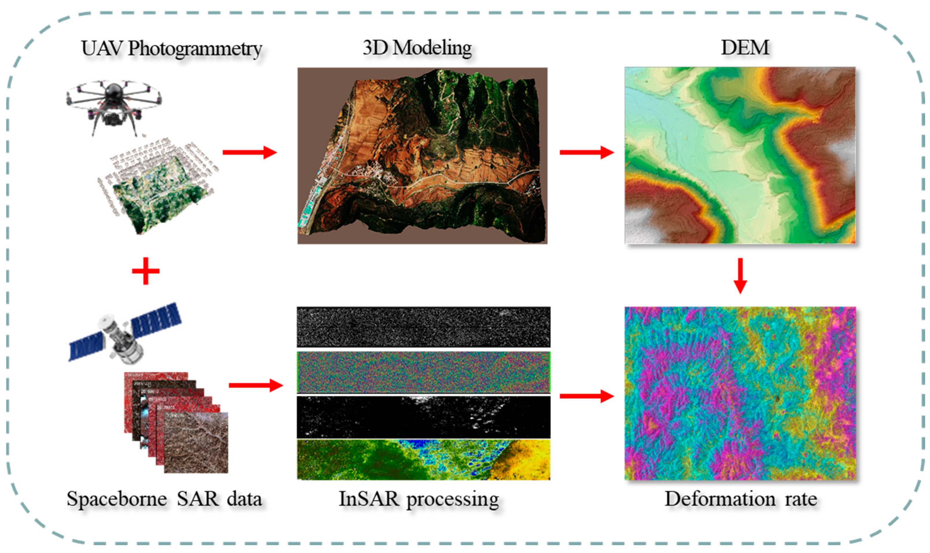
In this study, the Sentinel 1 SLC spaceborne SAR images from the European Space Agency (ESA) were selected as the data source for surface deformation monitoring with InSAR processing. For monitoring the surface deformation after CO2 injection, surface deformations in the year prior to and after injection were estimated by using InSAR technology in association with UAV photography measurement technology. 14 Sentinel 1 images were selected every 24 days since 25 June 2019 for InSAR processing to monitor surface deformation in the year prior to CO2 injection. Similarly, 14 Sentinel images were selected every 24 days since 2 June 2020 for InSAR processing to monitor surface deformation in the year after CO2 injection. At the same time, for improving accuracy in surface deformation monitoring and intuitively visualizing the underground migration pathway of injected CO2, the UAV photography measurement technology with 3D surface modelling at a resolution of 5.3 cm in the study area was adopted to extract the DEM of the study site. The flow chart for surface deformation retrieval in high accuracy is illustrated in Figure 2 below.

3.1. UAV 3D Surface Model Construction for DEM Extraction

UAV 3D modeling has a wide range of applications in the field of terrain monitoring with high-precision DEM construction for surface topographic and geomorphological analysis owing to its special capability in investigating and observing the object from various angles through a high-precision 3D model.
In the process of UAV 3D modeling, for ensuring the modeling accuracy and data integrity, the UAV flying route should be planned prior to guarantee that the flying route between two neighboring flights that horizontally overlap exceeds 80%, and vertically exceeds 70%. In this study, a DJI Phantom 4 RTK drone was used to build the UAV 3D model at the relative flight altitude of 100 m, and the DJI Terra software was used for data processing and 3D model generation. As shown in Figure 3, the establishment of UAV 3D model is divided into two parts: field data acquisition and indoor processing. First, through the literature data and on-site investigation, the appropriate route is designed. Ground control points (GCP) were selected in the appropriate area and measured with real-time kinematic (RTK). After the field UAV data were acquired through several processes, the UAV 3D surface model thus could be constructed through two essential processes, i.e., data inspection for image quality assessment and aerial triangulation with images in good quality for 3D model constructions.

3.2. InSAR Surface Deformation Information Based on UAV High-Precision DEM

InSAR technology has been adopted for monitoring surface deformation over the CO2 sequestration area with many years of successful experience, in which small baseline subset InSAR (SBAS-InSAR) technology is considered the most suitable deformation detection technology for CCS projects for its advantages in minimizing differences in time and perspective to maximize reference to trend surface and noise effects [34]. The basic principle for SBAS-InSAR technology is to use the deformation result obtained by a single D-InSAR that can provide centimeter- to millimeter-level records of terrain topographic changes and surface deformations as the observation value, and then estimate a high-precision deformation time series based on the least squares rule. The D-inSAR technique utilizes phase information in two or more SAR images taken at different times in the same area to form interferometric pairs. However, D-inSAR has a weakness limited to signal de-correlation at the specific land cover, which interferes with interpreting deformations [35]. For minimizing the effect of de-correlation, interferometric data with a short or small baseline are needed [36,37]. Therefore, the present study adopted the SBAS-InSAR approach in association with several essential processes currently being implemented, including removal of the influence of the atmosphere phase with high-pass filtering in the time domain and low-pass filtering in the space domain, and the elimination of phase differences caused by topographic relief with high-resolution DEM. A workflow mainly consisting of UAV-derived DEM data preprocessing, SBAS-InSAR processing and data process for refinement, as presented in Figure 4, was followed in this study. The relative coordinates are used in the interference processing, so it is necessary to extract the real surface deformation information through the geocoding of geographical coordinates.

4. Results

4.1. DEM Extraction by UAV

During the field work season, 1070 UAV images were acquired. Figure 5 shows the 3D UAV model of the CCUS site. According to 20 significant ground markers and control points, the calibration results suggested that the horizontal error of calibration points is about 0.053 m, and the elevation error is around 0.037 m.
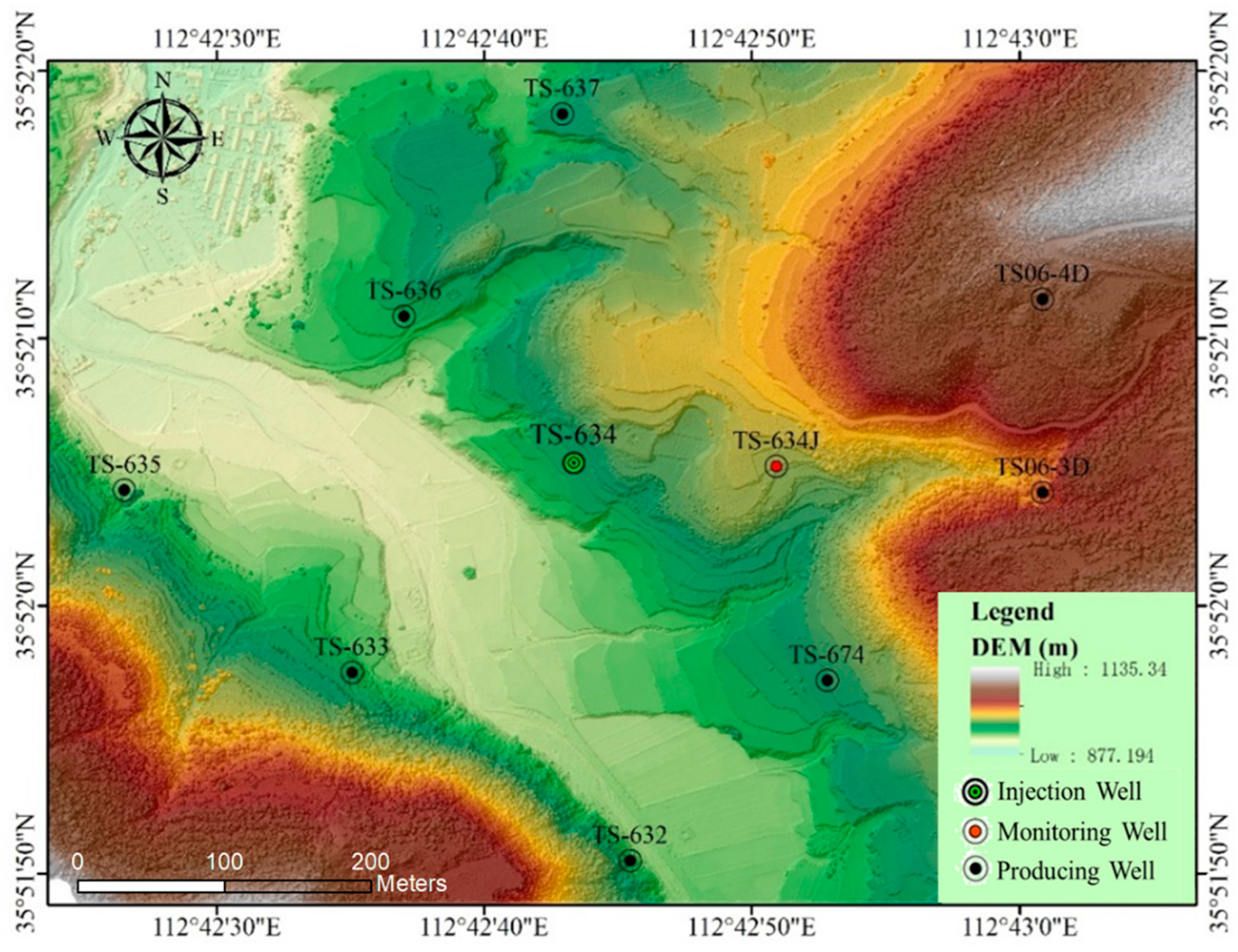
Figure 6 presented the DEM extracted from the 3D model of UAV. Along with topographic presentation of CCUS site, the geo-locations of injection wells, monitoring wells, and production well groups in the study site are marked clearly in the figure. The well marked as TS-634 in the middle of the CCUS site was selected as the injection well, and a nearby well marked as TS-634J, which was drilled in the east, was settled for monitoring with the many logging instruments deployed. For investigating the CO2 migration pathway and gas channeling after CO2 being injected, eight production wells were selected for pressure, temperature and gas composition analysis along the processes of the CCUS project being implemented.
The topography of the CCUS project site in the present study tends to be undulating with an elevation difference of about 250 m. Gentle hills dominate the landscape of the study site, accounting for about 64.45% in coverage. The topographic relief amplitude is classified as flat (0–10 m) and micro-relief (0–20 m), accounting for 79.72% and 20.28% of the area, respectively. However, the central part of the sequestration area, where the well groups are located, is flat and terraced with less vegetation covered, which ensures the accuracy of the InSAR technology being used. Moreover, due to the perennial coal-bed methane mining area, artificial influences such as construction and farming in this area are less, which is conducive to the analysis of InSAR deformation results.

4.2. Temporal InSAR Monitoring of the Study Area

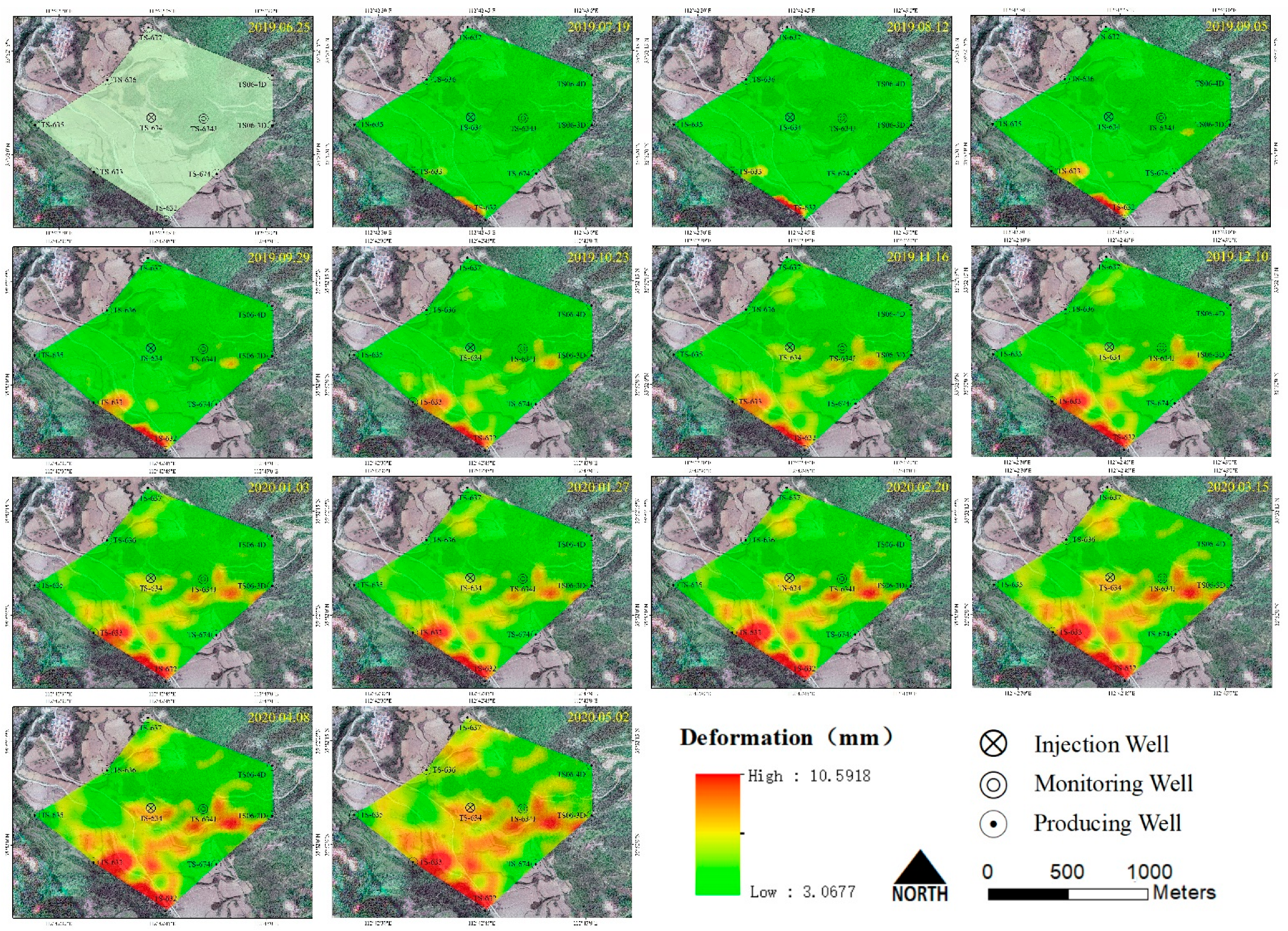
The DEM extracted by UAV was input into InSAR processing as the reference data, and the deformation background value before the injection was calculated. Figure 7 shows the accumulated surface deformation superimposed on the UAV model of 25 June 2019 for every 24-day interval for about a year before the CO2 was injected. No significant changes can be observed in the vicinity of the injection well TS-634 during the year prior to injection. However, on the southwest side of the injection area, there was some cumulative deformation, mainly in the vicinity of the production well TS-633, which was caused by production activity during the monitoring period. The maximum cumulative heaving in the area is about 10.598 mm. It can be considered that the study area was relatively stable before injection, especially near injection wells and monitoring wells, without obvious deformation.
Similarly, taking the surface status on 7 June 2020 as the benchmark, the accumulated surface deformation superimposed on the UAV model of 25 June 2019 for every 24-day interval for about a year after CO2 was injected is exhibited in Figure 8. The injection began on 15 June 2020. It can be seen that, in September 2020, when the injection volume reached 500 tons, deformation began to occur in the well and gradually spread to the northeast. As the injection continued, in March 2021, when the injection volume reached 1500 tons, a highly deformed channel was formed towards TS06-4D, with the maximum cumulative deformation up to 21 mm. However, in the later stage of injection, a large deformation was found in the southeast and southwest sides of the study area. Referring to the benchmark condition and the accumulative surface deformation of the study site in the year before injection, we believe that it is the surface morphological change caused by the production process. Meanwhile, the other important reason leads us to make this conclusion is that no high deformation channels were found connected to the injection well, which does not conform to the law of CO2 migration.

4.3. Verification of Multiple Monitoring Methods

InSAR monitoring results showed that the CO2 migration pathway did not form in the expected direction of the monitoring well TS-634J according to the early exploration of the China United Coalbed Methane Company. In order to analyze and verify the InSAR monitoring results, we conducted a comparative analysis with various on-site monitoring results, as shown in Figure 9.
Figure 9A exhibited the cumulative surface deformation rate derived by InSAR during injection. The overall migration trend of CO2 is northeast, with the largest cumulative deformation around the injection well, gradually migrating towards well TS06-4D and bypassing the monitoring well TS-634J. According to the previous analysis, the high deformation in the southwest and southeast is the surface morphological change caused by the production activities.
Figure 9B presented the measured stress direction and bottomhole pressure data in the field well, in which the red arrow refers to the minimum closing pressure direction and fracture development, the yellow one indicates the direction of low closing pressure and the blue one is the direction of high closing stress. It was observed that the low-stress areas all occurred in the north, northeast and east directions, which implies that the possible CO2 migration pathway should exist over there; moreover, the connect between the TS-634 and TS06-4D well is perpendicular to the direction of minimum principal stress, which also support that this direction is more conducive to form fractures as the CO2 migration pathway. From the perspective of well pressure, the stable pressure of TS-634 after injection was 12.5 MPa, and the pressure of the north and northeast wells TS-637, TS06-4D and TS-634J were all lower than that of the TS-634, but the pressure of the wells in the west and south were significantly higher, which also suggested that the wells in the north and northeast were more conducive to the migration of CO2 to a certain level.
Figure 9C illustrates the surface energy data obtained by the field micro-seismic measurement. Passive seismic tomography mainly uses the first break travel time tomography algorithm by means of its sensitivity to the energy change caused by shallow fragmentation due to CO2 injection for cross-well seismic and near surface velocity analysis, which is simple, intuitive and stable. Passive seismic monitoring was performed 30 days after CO2 injections in the TS-634 well (1 June 2021 to 30 June 2021). After normalized processing, the banded energy display in the south of well TS-634 was observed many times, which was an obvious indication that natural fractures or small faults exist there. These natural fractures or small faults are mainly NEE strike with the fault length about 700~800 m. These faults may form a barrier for CO2 migration to the south, which explains the reason why there is no CO2 migration pathway to the south. The stacking results of energy indicated that strong energy distribution from well TS-634 to TS06-4D existed, which was inferred as the main migration pathway of injected CO2. This phenomenon can also be explained from the perspective of in situ stress observations. With an increase of injected CO2 pressure, the northeast–southwest and north–south striking cracks in the coal seam, roof and floor began to open to form CO2 hypertonic channels due to the pressure exceeding the minimum principal stress in the northwest–southeast direction (11–12 MPa). Compared with InSAR results, it can be seen that the formation energy spreads along the fracture to the northeast side of the injection well, and its morphology and trend are basically consistent with InSAR monitoring results.
Figure 9D shows the formation contour diagram. From the topographic perspective, well TS06-4D is a higher formation area near the injection well. After gas is injected into the formation, it migrates to a place with lower pressure and higher ground, which further supports why the main migration pathway of CO2 is TS-634 to TS06-4D. Therefore, based on the comprehensive analysis of various monitoring results, we believe that the migration pathway from TS-634 to TS06-4D is relatively credible, and the InSAR monitoring results are reliable.
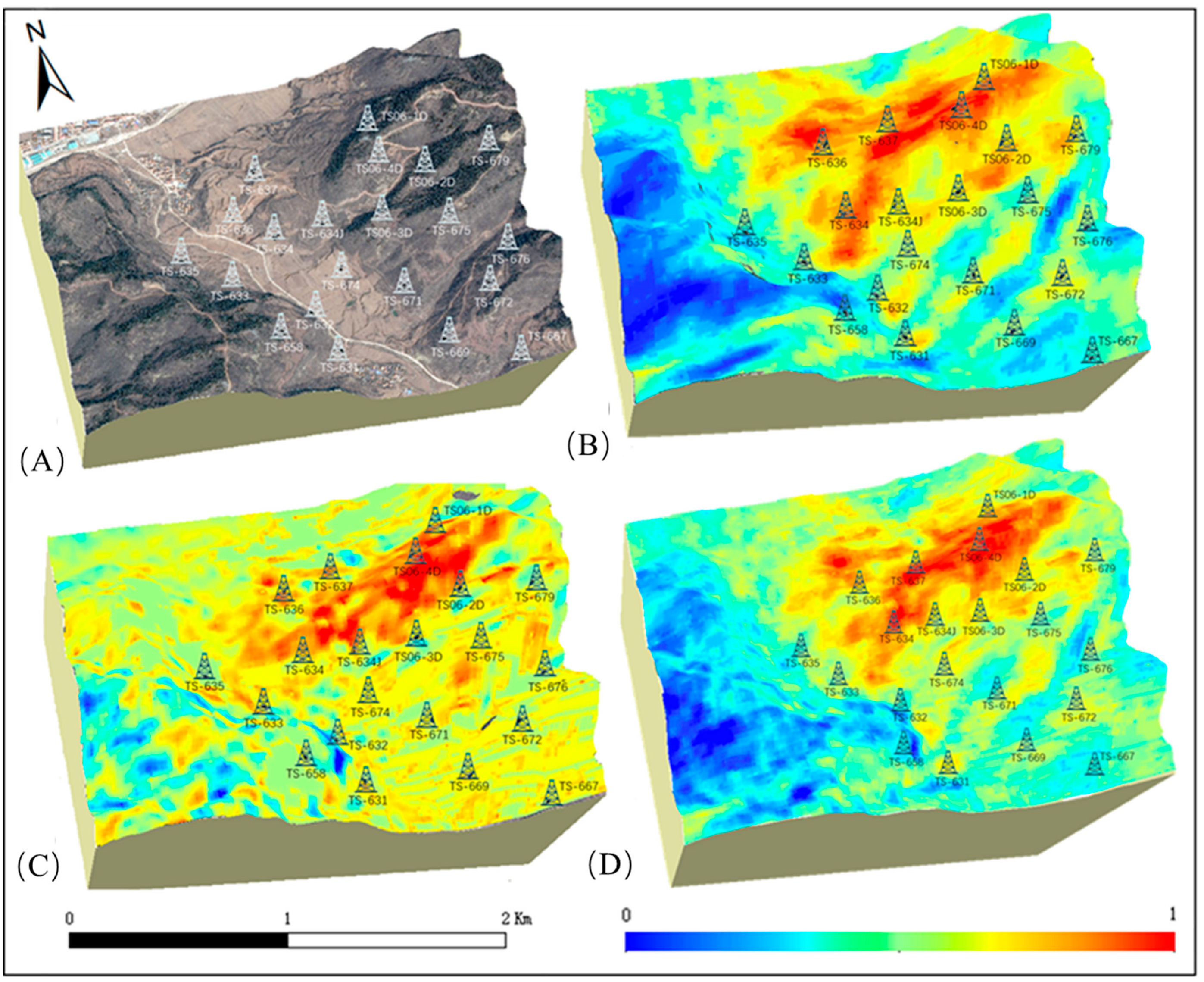
In the result analysis, the UAV model has its unique advantages. Superimposing a variety of monitoring results on the UAV model can intuitively display the migration of CO2 at the injection site. At the same time, in order to verify the results of different monitoring methods, we pay more attention to the migration direction rather than the specific deformation value. Therefore, we normalized the data of different monitoring results. In the InSAR monitoring results, the red area represents the heaving area, and the red area in the vertical seismic profiling (VSP) represents the strong energy field area, as shown in Figure 10. After the superposition of the results of the two monitoring methods, a migration pathway from injection well TS-634 to production well TS06-1D is more clearly displayed.

5. Discussion

InSAR monitoring is a unique method of tracking the entire CCUS injection process. Its wide monitoring range that is independent of weather and low monitoring cost will be important advantages for the future application in CCUS projects. However, there are still many aspects to be improved in the application of InSAR Technology in CCUS projects. First, most storage sites are far away from cities, which means that high vegetation coverage is inevitable. How to effectively remove the impact of vegetation on InSAR results is still an urgent problem to be solved. Secondly, the resolution of spaceborne data is still low, so it is difficult to obtain subtle changes near the study area. How to obtain more accurate data or choose more effective downscaling methods remains to be further explored.
Similarly, UAV, as a monitoring method that has developed by leaps and bounds in recent years, has the advantages of being flexible, fast and intuitive. The establishment of a three-dimensional model has an important and special contribution in the whole CCUS process. It can provide a layout reference for decision-makers during the design period. Real-time temperature, progress and leakage monitoring can be carried out in the injection process, and high-precision data can be provided for deformation monitoring after CO2 injection. Further, UAV photogrammetry is the best supplement and complement to the other traditional monitoring methods. The autonomous control of flight frequency makes it have more flexible and diverse monitoring scheme options than spaceborne satellites. The larger monitoring field of UAV is more efficient than the traditional surface monitoring method. UAV is a ‘bridge’ linking satellite base monitoring and ground base monitoring. In addition, the UAV can carry more environmental sensors, such as thermal infrared sensors, CO2 concentration sensors, hyperspectral sensors, etc., to monitor the CCUS storage site in an all-around way.
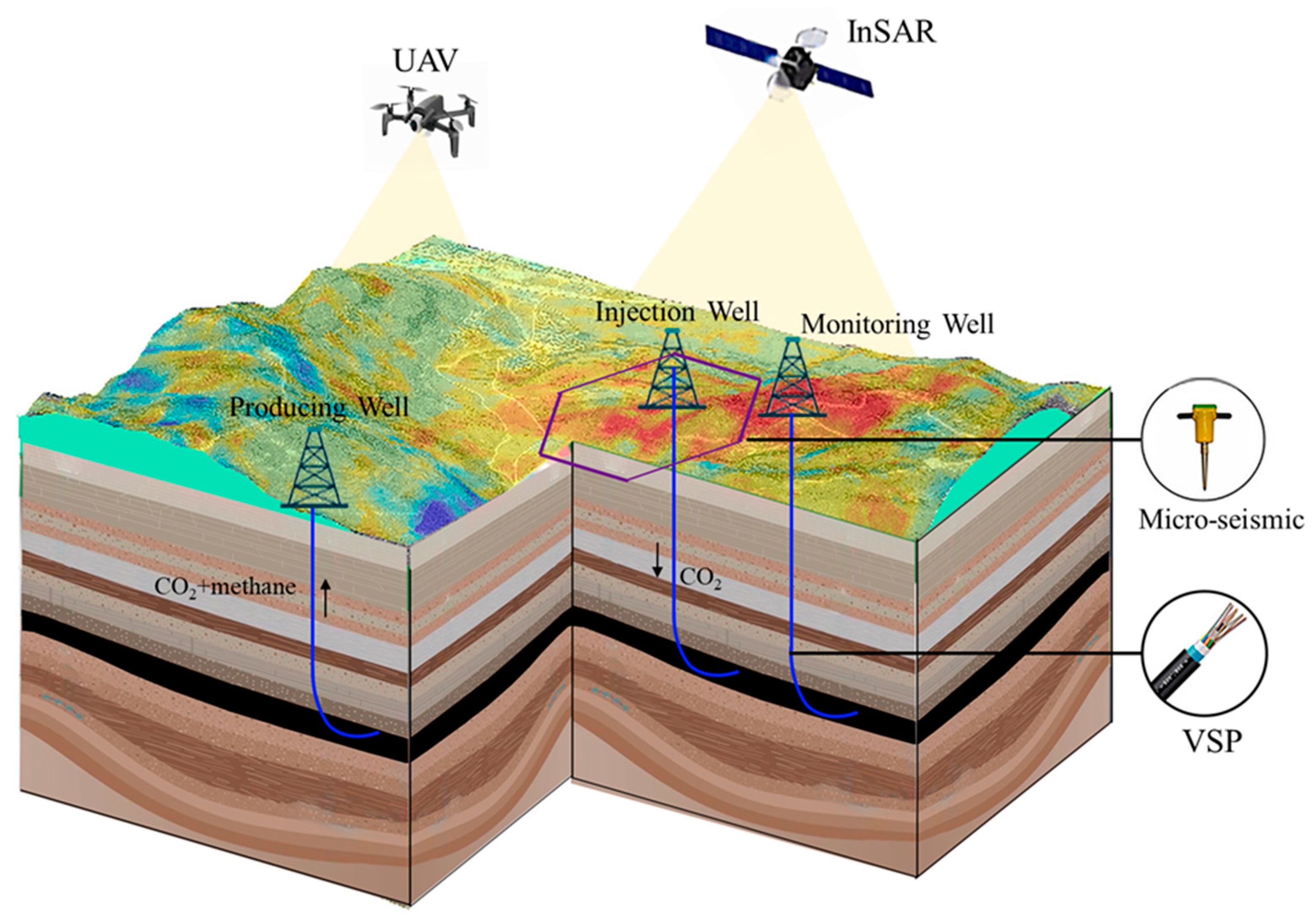
For the CCUS project, it is necessary to ensure the long-term safety and effectiveness during and after injection. Therefore, monitoring needs to include short-term monitoring and long-term monitoring. As shown in Figure 11, multi-method 3D monitoring is the development trend. Underground vertical seismic profiling (VSP) monitoring and microseismic monitoring can monitor the fracture and energy change caused by injection, so as to calculate the CO2 movement direction, while the UAV and spaceborne InSAR technology can monitor the surface deformation from the air, find the migration pathway through the heaving channel, and combine the field logging data to superimpose the results of various monitoring technologies on the UAV model, so as to realize clear 3D monitoring. At the same time, mutual verification also strengthens the accuracy of the results.

6. Conclusions

CO2 migration has always been a concern of CCUS projects. Traditional logging methods can only obtain the point monitoring results centered on the well. The micro-seismic method can predict the migration direction through fractures, while InSAR technology can intuitively and dynamically reflect the pathway of CO2 migration through surface deformation, which complements the important monitoring process. In this study, combining InSAR deformation detection technology with UAV three-dimensional model technology, the pathway of CO2 migration is clearly and stereoscopically displayed. Taking Shizhuang town, Jincheng City, Shanxi Province, China as an example, the formation and changes of CO2 migration pathway during CO2 injection were traced by monitoring the changes of surface deformation in the area before and after CO2 injection. Meanwhile, the results are superimposed on the UAV model to visually display the dynamic changes of surface deformation in the sealed area. The migration pathway from the injection well TS-634 to TS06-4D was monitored with a cumulative surface profile of 21 mm. Through the analysis and comparison of logging, micro-seismic and other monitoring results, it not only proved the accuracy of InSAR monitoring results and verified the reliability of the migration pathway, but also explained the reason why CO2 did not migrate to the monitoring well as expected. With the increasing global attention to carbon reduction, a complete set of commercializable CO2 storage and monitoring systems throughout the injection process and after injection is urgently needed. Multi-source and multi-scale air and space monitoring and mutual comparison and verification of various results can accurately identify dynamic and static changes in the CO2 sequestration area, which must be an important trend of CCUS project monitoring in the future.

Author Contributions

T.Z. designed this study. T.Z. performed the data collection, processing and analysis. R.Y., D.L. and L.M. provided logging results and micro-seismic data for this work. D.C. and L.C. optimized the figures for this work. The corresponding author W.Z. is the supervisor of this work and contributed with continuous guidance during this work. T.Z. jointly wrote this manuscript, and the manuscript was edited by W.Z. All authors have read and agreed to the published version of the manuscript.

Funding

This study was jointly financed by the National Key R & D Program of China (Grant No. 2018YFB0605603).

Acknowledgments

The authors are grateful to the anonymous reviewers for their constructive comments and suggestions to improve this manuscript.

Conflicts of Interest

The authors declare no conflict of interest.

References

  1. IPCC. Working Group I Climate Change 2021: The Physical Science Basis I; IPCC: Paris, France, 2021. [Google Scholar]
  2. Ryu, J.S.; Jacobson, A.D. CO2 evasion from the Greenland Ice Sheet: A new carbon-climate feedback. Chem. Geol. 2012, 320–321, 80–95. [Google Scholar] [CrossRef]
  3. Pohl, A.; Nardin, E.; Vandenbroucke, T.R.A.; Donnadieu, Y. High dependence of Ordovician ocean surface circulation on atmospheric CO2 levels. Palaeogeogr. Palaeoclimatol. Palaeoecol. 2016, 458, 39–51. [Google Scholar] [CrossRef]
  4. Wang, Z.; Yin, J.J.; Pu, J.; Xiao, Q.; Zhang, T.; Li, J. Flux and influencing factors of CO2 outgassing in a karst spring-fed creek: Implications for carbonate weathering-related carbon sink assessment. J. Hydrol. 2021, 596, 125710. [Google Scholar] [CrossRef]
  5. Yang, D.; Zhang, H.; Li, J. Changes in concentrations of fine and coarse particles under the CO2-induced global warming. Atmos. Res. 2019, 230, 104637. [Google Scholar] [CrossRef]
  6. Lee, Z.H.; Sethupathi, S.; Lee, K.T.; Bhatia, S.; Mohamed, A.R. An overview on global warming in Southeast Asia: CO2 emission status, efforts done, and barriers. Renew. Sustain. Energy Rev. 2013, 28, 71–81. [Google Scholar] [CrossRef]
  7. Anderson, T.R.; Hawkins, E.; Jones, P.D. CO2, the greenhouse effect and global warming: From the pioneering work of Arrhenius and Callendar to today’s Earth System Models. Endeavour 2016, 40, 178–187. [Google Scholar] [CrossRef] [PubMed] [Green Version]
  8. Wang, N.; Akimoto, K.; Nemet, G.F. What went wrong? Learning from three decades of carbon capture, utilization and sequestration (CCUS) pilot and demonstration projects. Energy Policy 2021, 158, 112546. [Google Scholar] [CrossRef]
  9. Li, Z.; Wang, F.; Shu, C.M.; Wen, H.; Wei, G.; Liang, R. Damage effects on coal mechanical properties and micro-scale structures during liquid CO2-ECBM process. J. Nat. Gas Sci. Eng. 2020, 83, 103579. [Google Scholar] [CrossRef]
  10. Zhang, Y.; Chi, Y.; Xing, W.; Liu, S.; Song, Y. Competitive Adsorption/Desorption of CH4/CO2/N2 Mixture on Anthracite from China for ECBM Operation. Energy Procedia 2017, 105, 4289–4294. [Google Scholar] [CrossRef]
  11. Norhasyima, R.S.; Mahlia, T.M.I. Advances in CO2 utilization technology: A patent landscape review. J. CO2 Util. 2018, 26, 323–335. [Google Scholar] [CrossRef]
  12. Niu, Q.; Wang, Q.; Wang, W.; Chang, J.; Chen, M.; Wang, H.; Cai, N.; Fan, L. Responses of multi-scale microstructures, physical-mechanical and hydraulic characteristics of roof rocks caused by the supercritical CO2-water-rock reaction. Energy 2022, 238, 121727. [Google Scholar] [CrossRef]
  13. Leung, D.Y.C.; Caramanna, G.; Maroto-Valer, M.M. An overview of current status of carbon dioxide capture and storage technologies. Renew. Sustain. Energy Rev. 2014, 39, 426–443. [Google Scholar] [CrossRef] [Green Version]
  14. Ren, B.; Ren, S.; Zhang, L.; Chen, G.; Zhang, H. Monitoring on CO2 migration in a tight oil reservoir during CCS-EOR in Jilin Oilfield China. Energy 2016, 98, 108–121. [Google Scholar] [CrossRef]
  15. Saleem, U.; Dewar, M.; Chaudhary, T.N.; Sana, M.; Lichtschlag, A.; Alendal, G.; Chen, B. Numerical modelling of CO2 migration in heterogeneous sediments and leakage scenario for STEMM-CCS field experiments. Int. J. Greenh. Gas Control 2021, 109, 103339. [Google Scholar] [CrossRef]
  16. Akai, T.; Kuriyama, T.; Kato, S.; Okabe, H. Numerical modelling of long-term CO2 storage mechanisms in saline aquifers using the Sleipner benchmark dataset. Int. J. Greenh. Gas Control 2021, 110, 103405. [Google Scholar] [CrossRef]
  17. Zhang, X.; Zheng, Y.; Guo, Z.; Ma, Y.; Wang, Y.; Gu, T.; Yang, T.; Jiao, L.; Liu, K.; Hu, Z. Effect of CO2 solution on Portland cement paste under flowing, migration, and static conditions. J. Nat. Gas Sci. Eng. 2021, 95, 104179. [Google Scholar] [CrossRef]
  18. Appriou, D.; Bonneville, A.; Zhou, Q.; Gasperikova, E. Time-lapse gravity monitoring of CO2 migration based on numerical modeling of a faulted storage complex. Int. J. Greenh. Gas Control 2020, 95, 102956. [Google Scholar] [CrossRef]
  19. Verkerke, J.L.; Williams, D.J.; Thoma, E. Remote sensing of CO2 leakage from geologic sequestration projects. Int. J. Appl. Earth Obs. Geoinf. 2014, 31, 67–77. [Google Scholar] [CrossRef] [Green Version]
  20. Chen, Y.; Guerschman, J.P.; Cheng, Z.; Guo, L. Remote sensing for vegetation monitoring in carbon capture storage regions: A review. Appl. Energy 2019, 240, 312–326. [Google Scholar] [CrossRef]
  21. Onuma, T.; Ohkawa, S. Detection of surface deformation related with CO2 injection by DInSAR at In Salah, Algeria. Energy Procedia 2009, 1, 2177–2184. [Google Scholar] [CrossRef] [Green Version]
  22. Zhang, T.; Zhang, W.; Yang, R.; Liu, Y.; Jafari, M. CO2 capture and storage monitoring based on remote sensing techniques: A review. J. Clean. Prod. 2021, 281, 124409. [Google Scholar] [CrossRef]
  23. Emilien, A.-V.; Thomas, C.; Thomas, H. UAV & satellite synergies for optical remote sensing applications: A literature review. Sci. Remote Sens. 2021, 3, 100019. [Google Scholar] [CrossRef]
  24. Bemis, S.P.; Micklethwaite, S.; Turner, D.; James, M.R.; Akciz, S.; Thiele, S.T.; Bangash, H.A. Ground-based and UAV-Based photogrammetry: A multi-scale, high-resolution mapping tool for structural geology and paleoseismology. J. Struct. Geol. 2014, 69, 163–178. [Google Scholar] [CrossRef]
  25. de Almeida, D.R.A.; Broadbent, E.N.; Ferreira, M.P.; Meli, P.; Zambrano, A.M.A.; Gorgens, E.B.; Resende, A.F.; de Almeida, C.T.; do Amaral, C.H.; Corte, A.P.D.; et al. Monitoring restored tropical forest diversity and structure through UAV-borne hyperspectral and lidar fusion. Remote Sens. Environ. 2021, 264, 112582. [Google Scholar] [CrossRef]
  26. Qadir, Z.; Ullah, F.; Munawar, H.S.; Al-Turjman, F. Addressing disasters in smart cities through UAVs path planning and 5G communications: A systematic review. Comput. Commun. 2021, 168, 114–135. [Google Scholar] [CrossRef]
  27. Sun, S.; Wang, B. Low-altitude UAV 3D modeling technology in the application of ancient buildings protection situation assessment. Energy Procedia 2018, 153, 320–324. [Google Scholar] [CrossRef]
  28. Teng, T.; Chen, X.; Li, P. Application of Unmanned Aerial Vehicle Remote Sensing Monitoring Technology on CO2 Sequestration and Leakage Risk Assessment. Bull. Soil Water Conserv. 2018, 38, 136–142. [Google Scholar] [CrossRef]
  29. Shi, J.; Zeng, L.; Zhao, X.; Zhang, Y.; Wang, J. Characteristics of natural fractures in the upper Paleozoic coal bearing strata in the southern Qinshui Basin, China: Implications for coalbed methane (CBM) development. Mar. Pet. Geol. 2020, 113, 104152. [Google Scholar] [CrossRef]
  30. Chen, B.; Stuart, F.M.; Xu, S.; Gyӧre, D.; Liu, C. Evolution of coal-bed methane in Southeast Qinshui Basin, China: Insights from stable and noble gas isotopes. Chem. Geol. 2019, 529, 119298. [Google Scholar] [CrossRef]
  31. Song, Y.; Ma, X.; Liu, S.; Jiang, L.; Hong, F.; Qin, Y. Accumulation conditions and key technologies for exploration and development of Qinshui coalbed methane field. Pet. Res. 2018, 3, 320–335. [Google Scholar] [CrossRef]
  32. Chen, S.; Tang, D.; Tao, S.; Xu, H.; Li, S.; Zhao, J.; Ren, P.; Fu, H. In-situ stress measurements and stress distribution characteristics of coal reservoirs in major coalfields in China: Implication for coalbed methane (CBM) development. Int. J. Coal Geol. 2017, 182, 66–84. [Google Scholar] [CrossRef]
  33. Ni, X.; Zhao, Z.; Wang, Y.; Wang, L. Optimisation and application of well types for ground development of coalbed methane from no. 3 coal seam in shizhuang south block in Qinshui basin, Shanxi province. China. J. Pet. Sci. Eng. 2020, 193, 107453. [Google Scholar] [CrossRef]
  34. Loschetter, A.; Rohmer, J.; Raucoules, D.; De Michele, M. Sizing a geodetic network for risk-oriented monitoring of surface deformations induced by CO2 injection: Experience feedback with InSAR data collected at In-Salah, Algeria. Int. J. Greenh. Gas Control 2015, 42, 571–582. [Google Scholar] [CrossRef]
  35. Cigna, F.; Sowter, A. The relationship between intermittent coherence and precision of ISBAS InSAR ground motion velocities: ERS-1/2 case studies in the UK. Remote Sens. Environ. 2017, 202, 177–198. [Google Scholar] [CrossRef]
  36. Pepe, A.; Calò, F. A review of interferometric synthetic aperture RADAR (InSAR) multi-track approaches for the retrieval of Earth’s Surface displacements. Appl. Sci. 2017, 7, 1264. [Google Scholar] [CrossRef] [Green Version]
  37. Qu, T.; Lu, P.; Liu, C.; Wan, H. Application of time series insar technique for deformation monitoring of large-scale landslides in mountainous areas of western China. Int. Arch. Photogramm. Remote Sens. Spat. Inf. Sci.—ISPRS Arch. 2016, XLI-B1, 89–91. [Google Scholar] [CrossRef] [Green Version]
Figure 1. Geographical location and optical image of the study area in southeast of Shanxi Province, China.
Remotesensing 14 00237 g001
Figure 2. Flow chart of CCUS deformation monitoring.
Remotesensing 14 00237 g002
Figure 3. Workflow for UAV 3D modeling.
Remotesensing 14 00237 g003
Figure 4. Workflow for InSAR surface deformation extraction.
Remotesensing 14 00237 g004
Figure 5. 3D UAV model of Shizhuang research area.
Remotesensing 14 00237 g005
Figure 6. Digital elevation model extract by UAV 3D model of the Shizhuang research area.
Remotesensing 14 00237 g006
Figure 7. The accumulated surface deformation superimposed on the UAV model of 25 June 2019 for every 24-day interval for about a year before CO2 was injected.
Remotesensing 14 00237 g007
Figure 8. The accumulated surface deformation superimposed on the UAV model of 25 June 2019 for every 24-day interval for about a year after CO2 was injected.
Remotesensing 14 00237 g008
Figure 9. Comprehensive comparisons and verification graph of various methods. (A) Cumulative surface deformation derived by InSAR during CO2 injection, (B) field stress distribution and bottom hole pressure for wells, (C) micro-seismic detection results during injection and (D) contour map of underground reservoir.
Remotesensing 14 00237 g009
Figure 10. (A) UAV 3D model with well distribution, (B) UAV 3D model with microseismic monitoring results, (C) UAV 3D model with InSAR monitoring results and (D) UAV 3D model with monitoring results superposition.
Remotesensing 14 00237 g010
Figure 11. Schematic diagram of multi-method monitoring at the CCUS project.
Remotesensing 14 00237 g011
Publisher’s Note: MDPI stays neutral with regard to jurisdictional claims in published maps and institutional affiliations.