Article

Effect of 6-DOF Oscillation of Ship Target on SAR Imaging

1
Department of Spaceborne Microwave Remote Sensing System, Aerospace Information Research Institute, Chinese Academy of Sciences, Beijing 100190, China
2
School of Electronics, Electrical and Communication Engineering, University of Chinese Academy of Sciences, Beijing 100049, China
*
Author to whom correspondence should be addressed.
Remote Sens. 2021, 13(9), 1821; https://doi.org/10.3390/rs13091821
Submission received: 27 March 2021 / Revised: 26 April 2021 / Accepted: 3 May 2021 / Published: 7 May 2021
(This article belongs to the Special Issue Feature Paper Special Issue on Ocean Remote Sensing)

Abstract

:
Ship targets are high-value military and civilian targets with broad application prospects. However, the precise focusing of ships is still a difficult issue because of their complicated six-degree-of-freedom motions on the sea surface. This paper focused on investigating the effect of ship six-degree-of-freedom oscillation on Synthetic Aperture Radar imaging. Firstly, based on the six-degree-of-freedom motions, the accurate range models for ship linear oscillation and angular oscillation were built, and the superiority was verified by comparing them with the models described in published literature. Secondly, we used the Taylor formula and Bessel function to expand the phase error introduced by ship oscillation, then their effects on imaging were further analyzed. Finally, based on the measured ship attitude data, we generated the semi-physical echoes of the oscillatory ship to validate the analysis throughout this article. Based on the proposed range model, we also made some tentative on the phase compensation method by fitting ship attitude angles with multiple sinusoidal functions.

1. Introduction

Ship targets are high-value military and civilian targets with broad application prospects, so it is of great significance to obtain high-quality ship images in all conditions. Synthetic Aperture Radar (SAR) is an advanced active aerospace microwave remote sensing method, which can provide high-resolution images in all-weather and all-time, so it is very suitable for imaging and recognition of marine vessels [1]. However, affected by sea breezes and waves, the ships on sea surface often have complex forms of movements, which significantly increases the difficulty of precise focusing.
A vessel floating on the surface of an undulating sea wave will move (e.g., oscillation, nonuniform acceleration) according to its transfer functions and the properties of the passing wave [2]. It is important to accurately describe the motion state of the ship, which is essential to the pulse propagation distance calculation and SAR focusing. Excluding its sailing, the ship’s micromotion on the sea surface can be described as six-degree-of-freedom (6-DOF) motion. The actual motion parameters of the ship are time-varying, and it is so complicated that it can hardly be expressed through analytical expressions. However, due to the interaction between ship and complex ocean environment, based on seakeeping theory of deep-water platform, ship motion can be generally viewed as the superposition of surge, sway, heave, roll, pitch, and yaw with a multi-frequency motion [3,4]. Therefore, it is possible to approximately derive the phase distortions introduced by 6-DOF oscillation and make a qualitative analysis of their effects.
In recent years, ship oscillation and its effect are gaining increasingly widespread interest, which is an unavoidable problem in ship high-resolution imaging. In 2001, Ouchi et al. first described the phenomenon of nonuniform azimuth images shift observed in the RADARSAT images of cruising ships, which was caused by the pitch and roll motion of the ship [5]. In 2008, Doerry of the Sandia National Laboratories submitted a report on ship dynamics for maritime ISAR imaging, which detailed the ship dynamic motions and analyzed their effect on ISAR imaging [6]. In 2011, Li et al., analyzed the influence of typical target micromotions on SAR images, azimuth resolution limit, and ground moving target indication (GMTI), the micromotion types include rotation, vibration, sinusoidal motion, and rocking [7]. In more detail, the imaging distortions induced by each rotation of a moving ship are quantitatively investigated through numerical simulations by Liu et al. Furthermore, a systematic analysis shows that these distortions can be characterized by four main types of transformations, namely, translation, rotation, scaling, and shearing [8]. Besides, the focusing challenges of ships with oscillatory motions and long coherent processing intervals were discussed in [9].
On the other hand, these imaging distortions would carry much valuable information about the moving ship, and it may help refocus the smeared image. For example, Filippo et al. used pixel tracking and convex optimization to estimate the micromotion and inclination angle of the ships in the Cosmo-Skymed SAR data [10,11]. The imaging algorithm faces many challenges due to the complex three-dimensional oscillation of ship targets on the sea surface. However, this motion also provides more target observation angles and more information on the target in theory. Therefore, it is possible to realize 3D imaging of ship targets according to different imaging planes [12,13].
Besides, some researches related to the time-critical targets also have implications. In 2007, through a thorough motion analysis in a standard SAR system model, Ruegg et al., showed the effects of rotation and vibration in Millimeter-Wave SAR theoretically in simulated and real data [14]. Paired echoes are the typical manifestation of Doppler characteristics caused by vibrating targets in high-resolution SAR, and [15] proposed a method for paired echo focusing and suppression of vibrating targets. Accurate estimation of target micromotion can be helpful to compensate the phase error, and the precise extraction and measurement methods of micromotion characteristic and micro-Doppler feature are given respectively in [16,17]. Moreover, using an autoregressive moving average (ARMA) model including a sinusoidal covariate for spectral analysis may help to extract the characteristics of ship oscillation [18].
However, the in-depth analysis of ship oscillation is still limited since the lack of the ship attitude data matching SAR echo data. An effective way to solve this problem is to establish the ship motion model and SAR imaging simulations in which the motions of the ship and radar platform are both numerically parameterized. For example, Margarit et al. presented a SAR simulator to generate SAR and ISAR data of ship targets, and several motion effects were also considered [19,20]. Moreover, the model establishment of the ship target in the sea scene was systematically discussed in [21,22]. Besides, Cochin et al. developed a software named MOCEM to produce high-resolution SAR images from CAD models [23], and version 4 included new features to simulate the radar raw data of a maritime scene composed of a ship on a dynamic sea surface [24].
Although much work has been carried out to analyze the impact of ship micromotion on SAR/ISAR imaging, there are still some issues that need to be settled:
(1)
The state-of-the-art researches concerning ship oscillation and SAR imaging are relatively dispersed, and there is no systematic description and derivation of the phase distortion introduced by ship 6-DOF oscillation;
(2)
The ship oscillation in most of the existing analyses are obtained through numerical simulation, and part of the conclusions lack the verification by measured attitude data.
The above problems are what this paper is dedicated to solving. The organization of this paper is as follows. In Section 2, based on the 6-DOF motion, the accurate range models for ship linear oscillation and angular oscillation were built, and the superiority was verified by comparing them with the models described in [7]. In Section 3, through using the Taylor formula and Bessel function to expand the phase error introduced by ship oscillation, we further analyzed its effect on imaging. In Section 4, we first briefly introduced the ship attitude data collected in the field campaign. Then, the semi-physical echoes of the oscillatory ship were generated to analyze the impact of oscillation on imaging. Besides, based on the proposed range model, we also made some tentative research on the phase compensation method by fitting ship attitude angles with multiple sinusoidal functions. Finally, Section 5 is a summary.

2. Model of Oscillatory Ship Target

The geometry and range model of an oscillatory ship target is introduced in this section. Based on the 6-DOF motion, the accurate range models for ship linear oscillation and angular oscillation were built. To make the equations and schematic diagrams in this paper more concise, some repeated symbols and their meanings are listed in Table 1.

2.1. Range Model of a Ship Target Based on 6-DOF Motion

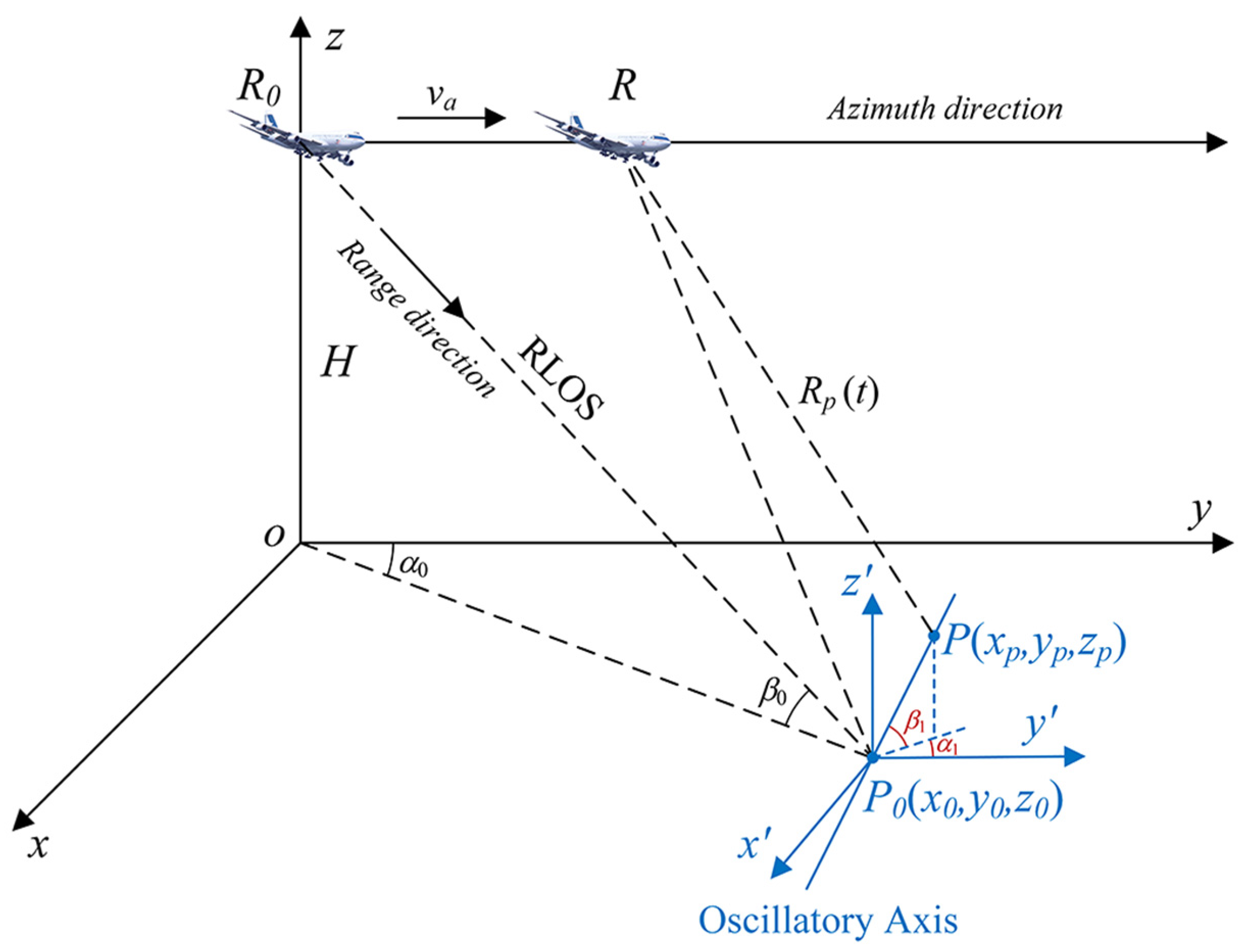
Affected by sea breezes and waves, the sea-surface targets often have complex micromotion, which can be described as the 6-DOF motion. The geometry of a ship’s 6-DOF motion is shown in Figure 1.
In Figure 1, O-XYZ is the ship-fixed coordinate system whose origin is located at the centroid of the ship. The X-axis is the longitudinal axis, and the bow indicates the positive direction of X. The Y-axis is the transverse axis, which is perpendicular to the longitudinal section of the ship, and the left side of the ship’s sailing direction is the positive direction. The Z-axis is the vertical axis, which is perpendicular to the X-axis and Y-axis, and these three axes constitute a three-dimensional Cartesian coordinate system. The ship-fixed coordinate system moves and oscillates with the ship, which is used to describe the positions of targets relative to the ship centroid. The o′-x′y′z′ is an interim space coordinate system that sails with the ship but does not oscillate, and it is consistent with O-XYZ at the initial time. This coordinate system is used to describe the micromotion of the ship.
The definitions of the ship’s 6-DOF motion is shown in Table 2 [6]. These six motions can be simply classified into two categories, the linear oscillation of a ship along three axes and the angular oscillation of a ship around those three axes. The serial numbers in the table correspond to those in Figure 1.
Due to the interaction between ship and complex ocean environment, based on seakeeping theory of deep-water platform, ship motion is generally viewed as the superposition of surge, sway, heave, roll, pitch, and yaw with a multi-frequency motion [3,4]. As an ideal rigid target, the displacements caused by ship linear oscillation can be expressed as follows:
{ Δ X = i = 1 N x A x , i sin ( ω x , i t + φ x , i ) Δ Y = i = 1 N y A y , i sin ( ω y , i t + φ y , i ) Δ Z = i = 1 N z A z , i sin ( ω z , i t + φ z , i ) ,
where Δ X , Δ Y , Δ Z represent the displacements caused by the ship’s surge, sway, and heave, respectively. A x , i , A y , i , A z , i , ω x , i , ω y , i , ω z , i , φ x , i , φ y , i , φ z , i are the amplitudes, angular frequencies, and initial phases for the i-th component of surge, sway, and heave, respectively. Nx, Ny, Nz indicate the numbers of frequency components associated with surge, sway, and heave.
The rotation angles of roll, pitch, and yaw can be written as
{ θ x = i = 1 M x B x , i sin ( Ω x , i t + Ψ x , i ) θ y = i = 1 M y B y , i sin ( Ω y , i t + Ψ y , i ) θ z = i = 1 M z B z , i sin ( Ω z , i t + Ψ z , i ) ,
where θ x , θ y , θ z represent the rotation angles of roll, pitch, and yaw. B x , i , B y , i , B z , i , Ω x , i , Ω y , i , Ω z , i , Ψ x , i , Ψ y , i , Ψ z , i are the amplitudes, angular frequencies, and initial phases for the i-th component of roll, pitch, and yaw, respectively. Mx, My, Mz indicate the numbers of frequency components associated with roll, pitch, and yaw.
Assuming that there is a point P on the ship, its coordinate in the ship-fixed coordinate system is (Xp, Yp, Zp). Thus, the position of point P in the o′-x′y′z′ coordinate system at time t can be derived by the following coordinate transformation:
[ x p ( t ) y p ( t ) z p ( t ) ] = R o t 1 ( θ x , θ y , θ z ) [ X p + Δ X Y p + Δ Y Z p + Δ Z ] ,
R o t 1 ( θ x , θ y , θ z ) = [ 1 0 0 0 cos θ x sin θ x 0 sin θ x cos θ x ] [ cos θ y 0 sin θ y 0 1 0 sin θ y 0 cos θ y ] [ cos θ z sin θ z 0 sin θ z cos θ z 0 0 0 1 ] .
Next, based on the 6-DOF motion, the range model of a ship target can be established, the geometry of a navigating ship is shown in Figure 2. The o-xyz is a fixed space coordinate system, whose y-axis is parallel to the direction of radar movement. At the initial moment, the projection of aircraft on the sea level is at the origin o, and the coordinate of the ship’s centroid in the o-xyz coordinate system is (x0, y0, z0).
Assuming that the ship has periodic linear oscillation (surge, sway, heave) and angular oscillation (roll, pitch, yaw) in addition to the uniform sailing. Combined with the coordinate rotation matrix, the point P in o-xyz coordinate system can be expressed as
[ x p ( t ) y p ( t ) z p ( t ) ] = R o t 2 ( α v ) ( [ x p ( t ) y p ( t ) z p ( t ) ] + [ 0 v s t 0 ] ) + [ x 0 y 0 z 0 ] ,
R o t 2 ( α v ) = [ cos α v sin α v 0 sin α v cos α v 0 0 0 1 ] .
The coordinate of the radar platform can be written as
[ x r ( t ) y r ( t ) z r ( t ) ] T = [ 0 v a t H ] T .
Finally, the slant distance between the point P and the antenna phase center can be expressed as
R p ( t ) = ( x r ( t ) x p ( t ) ) 2 + ( y r ( t ) y p ( t ) ) 2 + ( y r ( t ) y p ( t ) ) 2 .
Based on the above formulas, a range model of a ship target based on 6-DOF motion is given, which can be used to further analyze the phase and Doppler history of the oscillating target and generate the SAR raw data.

2.2. Ship Linear Oscillation

The linear oscillation of ships includes three types: surge, sway, and heave. They are all linear reciprocating motions along one axis of the ship. The only difference is the direction of oscillatory axis. Considering that the bow may point to any direction, and to simplify the derivation process, we analyzed these three kinds of linear oscillations based on a point target oscillating along any direction. The geometric model of a point target with linear oscillation is shown in Figure 3.

2.2.1. Single-Frequency Linear Oscillation

As the approximate form in a short time, a single-frequency linear oscillation model is first considered. Supposing that the point P oscillates with the fixed point P0 (x0, y0, z0), the displacement of point P can be decomposed into three axes:
{ Δ x = A l sin α 1 cos β 1 sin ( ω l t + φ l ) Δ y = A l cos α 1 cos β 1 sin ( ω l t + φ l ) Δ z = A l sin β 1 sin ( ω l t + φ l ) ,
where A l , ω l , φ l represent the amplitude, angular frequency, and initial phase of the linear oscillation, respectively.
According to the results of [7], the distance between the oscillating point P and the antenna phase center can be approximately expressed as
R p ( t ) = ( x 0 + Δ x ) 2 + ( v a t y 0 Δ y ) 2 + ( H z 0 Δ z ) 2 R P 0 + P 0 P cos P P 0 , R P 0 R P 0 + P 0 P cos P P 0 , R 0 P 0 = x 0 2 + ( v a t y 0 ) 2 + ( H z 0 ) 2 + A l C 0 sin ( ω l t + φ l ) ,
C 0 = sin β 0 sin β 1 cos β 0 c o s β 1 cos ( α 0 + α 1 ) ,
where C0 represents the cosine value of the angle between the oscillating axis and RLOS at the center moment.
However, since the neglect of the radar platform movement while calculating cos P P 0 , R P 0 , this approximate formula would lead to intolerable errors in some cases. To reduce the range error caused by projection deviation, we rewrote this item:
cos P P 0 , R P 0 = x 0 cos β 1 sin α 1 ( v a t y 0 ) cos β 1 cos α 1 + H sin β 1 x 0 2 + ( v a t y 0 ) 2 + H 2 = H sin β 1 H cot β 0 cos β 1 cos ( α 0 + α 1 ) v a t cos β 1 cos α 1 ( H csc β 0 ) 2 + ( v a t ) 2 + 2 H v a t cot β 0 cos α 0 k t ( C 0 v a sin β 0 cos β 1 cos α 1 H t ) ,
k t = 2 H 2 2 H 2 + sin 2 β 0 [ ( v a t ) 2 + 2 H v a t cos β 0 cos α 0 ] ,
where coefficient kt is the reciprocal of a quadratic polynomial, and it can be ignored when observation time is short or grazing angle is small.
Then, a more accurate range equation for the target with linear oscillation can be expressed as follows:
R p ( t ) R P 0 + P 0 P cos P P 0 , R P 0 x 0 2 + ( v a t y 0 ) 2 + ( H z 0 ) 2 + A l k t ( C 0 v a sin β 0 cos β 1 cos α 1 H t ) × sin ( ω l t + φ l ) .
Comparing the above formulas, it can be found that Equation (14) can be reduced to Equation (10) when ignoring the time-varying coefficient kt and the first-order term in the bracket. In the derivation of the new range approximate equation, the main modification was replacing the constant cos P P 0 , R 0 P 0 with variable cos P P 0 , R P 0 , which can better represent the projection direction of target oscillation. In the second item of Equation (14), the coefficient of the linear term is much smaller than the constant C0 in most scenarios, which does not have a great impact on the range. However, when C0 ≈ 0, such as the radar works in the side-looking mode and the target oscillates along the azimuth direction, the linear term would become dominant. However, in this case, the range model in [7] shows that the range distortion introduced by target linear oscillation is zero, which is unreasonable. In order to compare the fitting effects of these two approximate methods, an experiment was conducted with a set of typical parameters: A l = 1 m, ω l = 2 π / 3 rad/s, φ 0 = 0 ° , v a = 140 m/s, H = 6 km, f c = 5.4 GHz, α 0 = 90 ° , β 0 = 40 ° . The simulation results are shown in Figure 4.
As shown in Figure 4a, both methods can achieve good fitting results when the target oscillates along the range direction. However, the method in [7] still has little error as shown in the partial enlarged view, which is mainly due to the neglect of the change of R P 0 when calculating cos P P 0 , R P 0 . Furthermore, this error was reduced by adding the time-varying coefficient kt in Equation (14). In Figure 4b, the model in [7] showed a quite large fitting error when the target oscillates along the azimuth direction, and the distortion envelope is linearly modulated. This error is mainly derived from ignoring the change of projection direction, and it was also improved by adding the first-order term to the constant C0.
Next, continue to derive the Doppler frequency introduced by the target linear oscillation. The Doppler history of point P can be divided into two parts:
f d ( t ) = 2 λ d R p ( t ) d t = f d _ r e f ( t ) + f d _ m ( t ) ,
where f d denotes the total Doppler caused by the relative motion between the radar platform and target, f d _ r e f represents the reference Doppler generated by the radar platform movement, and f d _ m represents the micro-Doppler caused by the target oscillation. Moreover, these two components in the above formula can be expressed as
f d _ r e f ( t ) = 2 λ ( v a t y 0 ) v a x 0 2 + ( v a t y 0 ) 2 + H 2 ,
f d _ m ( t ) 2 λ A l ω l k t ( C 0 v a sin β 0 cos β 1 cos α 1 H t ) × cos ( ω l t + φ l ) 2 λ A l [ k t C 0 v a sin β 0 cos β 1 cos α 1 H ( k t t + k t ) ] × sin ( ω l t + φ l ) ,
k t = sin 2 β 0 H 2 k t 2 ( v a 2 t + H v a cos β 0 cos α 0 ) .
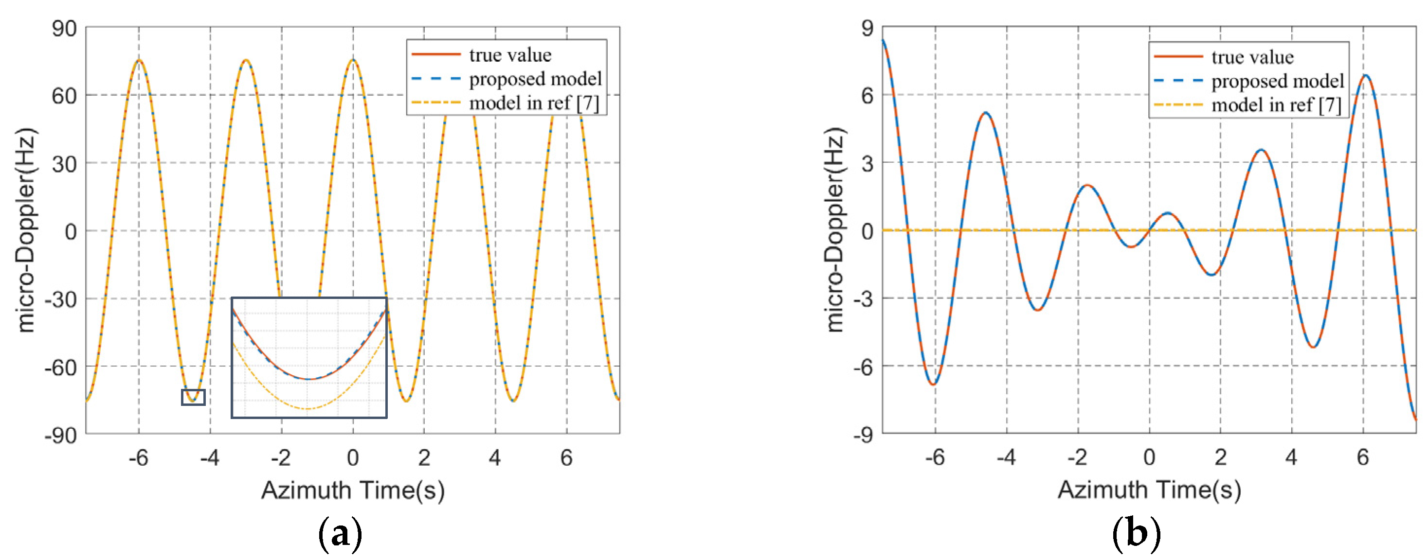
According to Equation (17), the micro-Doppler introduced by the target linear oscillation can be expressed as the superposition of two modulated cosine and sine in which the former is usually the dominant term. Similar to the range error, the micro-Doppler will show an obvious linear modulation phenomenon when C0 is close to zero. Figure 5 shows the micro-Doppler history caused by target linear oscillation.

2.2.2. Multi-Frequency Linear Oscillation

In this subsection, a point target incorporating multi-frequency linear oscillation model is considered. Similar to the former analysis, the displacement of point P can be decomposed into three axes:
{ Δ x = sin α 1 cos β 1 i = 1 N l A l , i sin ( ω l , i t + φ l , i ) Δ y = cos α 1 cos β 1 i = 1 N l A l , i sin ( ω l , i t + φ l , i ) Δ z = sin β 1 i = 1 N l A l , i sin ( ω l , i t + φ l , i ) ,
where A l , i , ω l , i , φ l , i represent the amplitude, angular frequency, and initial phase of the i-th frequency component, respectively. Nl indicates the number of frequency components associated with linear oscillation.
Then, the range equation and micro-Doppler for the target with multi-frequency linear oscillation can be respectively expressed as follows:
R p ( t ) x 0 2 + ( v a t y 0 ) 2 + ( H z 0 ) 2 + k t ( C 0 v a sin β 0 cos β 1 cos α 1 H t ) i = 1 N l A l , i sin ( ω l , i t + φ l , i ) ,
f d _ m ( t ) 2 λ k t ( C 0 v a sin β 0 cos β 1 cos α 1 H t ) × i = 1 N l ω l , i A l , i cos ( ω l , i t + φ l , i ) 2 λ [ k t C 0 v a sin β 0 cos β 1 cos α 1 H ( k t t + k t ) ] i = 1 N l A l , i sin ( ω l , i t + φ l , i ) .

2.3. Ship Angular Oscillation

The angular oscillation of ships includes three types: roll, pitch, and yaw. The most obvious motion is rolling, which has minimal damping with a typical hull form [6]. In fact, these three angular oscillations are not mutually independent, and the coupling between these motions would change the states of each oscillation [25,26]. In this subsection, we only made some tentative researches on the uncoupled angular oscillations based on the rotation matrix. Considering that the sailing of the ship will not affect the angular oscillation in our model, we assumed that the ship is berthed, and the ship centroid is located at the fixed point P0 (x0, y0, z0). The geometric model is shown in Figure 6.

2.3.1. Single-Frequency Angular Oscillation

As the approximate form in a short time, a single-frequency angular oscillation model is first considered. The rotation angles of ship roll, pitch, and roll can be written as
{ θ x = B x sin ( Ω x t + Ψ x ) θ y = B y sin ( Ω y t + Ψ y ) θ z = B z sin ( Ω z t + Ψ z ) ,
where B x , B y , B z , Ω x , Ω y , Ω z , Ψ x , Ψ y , Ψ z are the amplitudes, angular frequencies, and initial phases of roll, pitch, and yaw, respectively.
The coordinate of point P in the ship-fixed coordinate system is (Xp, Yp, Zp). Based on Equation (5), the coordinate of P in space coordinate system o-xyz can be expressed as
[ x p ( t ) y p ( t ) z p ( t ) ] = R o t 2 ( α v ) · R o t 1 ( θ x , θ y , θ z ) [ X p Y p Z p ] + [ x 0 y 0 z 0 ] ,
where R o t 2 ( α v ) and R o t 1 ( θ x , θ y , θ z ) represent the coordinate rotation matrixes.
Considering that the RLOS is changing with the radar platform position, the slant range of the target with angular oscillation can be written as
R p ( t ) = x p ( t ) 2 + ( v a t 0 y p ( t ) ) 2 + ( H z p ( t ) ) 2 R P 0 + P 0 P cos P P 0 , R P 0 x p 0 2 + ( v a t y p 0 ) 2 + ( H z p 0 ) 2 + k t [ sin ( α v α 0 ) cos β 0 sin α v sin β 0 v a t / H cos ( α v α 0 ) cos β 0 + cos α v sin β 0 v a t / H sin β 0 ] T R o t 1 ( θ x , θ y , θ z ) [ X p Y p Z p ] ,
where x p 0 , y p 0 , z p 0 denote the coordinates of point P in the fixed space coordinate system at the initial moment.
By substituting the rotation matrix in Equation (4) into Equation (24), the range distortions introduced by roll, pitch, and yaw motion can be respectively expressed as
R p _ r o l l ( t ) = k t [ sin ( α v α 0 ) cos β 0 sin α v sin β 0 v a t / H cos ( α v α 0 ) cos β 0 cos θ x + cos α v sin β 0 cos θ x v a t / H + sin β 0 sin θ x cos ( α v α 0 ) cos β 0 sin θ x cos α v sin β 0 sin θ x v a t / H + sin β 0 cos θ x ] T [ X p Y p Z p ] ,
R p _ p i t c h ( t ) = k t [ sin ( α v α 0 ) cos β 0 cos θ y sin α v sin β 0 cos θ y v a t / H sin β 0 sin θ y cos ( α v α 0 ) cos β 0 + cos α v sin β 0 v a t / H sin ( α v α 0 ) cos β 0 sin θ y sin α v sin β 0 sin θ y v a t / H + sin β 0 cos θ y ] T [ X p Y p Z p ] ,
R p _ y a w ( t ) = k t [ sin ( θ z α v + α 0 ) cos β 0 + sin ( θ z α v ) sin β 0 v a t / H cos ( θ z α v + α 0 ) cos β 0 + cos ( θ z α v ) sin β 0 v a t / H sin β 0 ] T [ X p Y p Z p ] .
From Equations (25)–(27), the range distortions introduced by single-frequency roll, pitch, and yaw can be viewed as the superposition of composite sinusoidal functions, and part of the terms are linearly modulated. When all the three angular oscillations exist, the range expression will become extremely complicated, and the specific derivation results can be seen in Appendix A.
Considering that the roll motion usually has the largest amplitude of the angular oscillations, we took it as an example to analyze the ship angular oscillation. Based on the auxiliary angle formula, Equation (25) can be rewritten as
R p _ r o l l ( t ) = k t cos ( α v α 0 ) cos β 0 ( Z p sin θ x Y p cos θ x ) + k t sin β 0 ( Y p sin θ x + Z p cos θ x ) + k t sin β 0 v a t / H [ cos α v ( Y p cos θ x Z p sin θ x ) sin α v X p ] + k t sin ( α v α 0 ) cos β 0 X p = k t { L x _ 1 cos [ B x sin ( Ω x t + Ψ x ) + θ x 0 _ 1 ] + L x _ 2 cos [ B x sin ( Ω x t + Ψ x ) + θ x 0 _ 2 ] t + L x 0 } ,
L x _ 1 = Y p 2 + Z p 2 cos 2 ( α v α 0 ) cos 2 β 0 + sin 2 β 0 L x _ 2 = Y p 2 + Z p 2 cos α v sin β 0 v a / H θ x 0 _ 1 = arctan cos ( α v α 0 ) cos β 0 Z p + sin β 0 Y p cos ( α v α 0 ) cos β 0 Y p sin β 0 Z p θ x 0 _ 2 = arctan Z p Y p L x 0 = sin α v sin β 0 X p v a t H + sin ( α v α 0 ) cos β 0 X p ,
where L x _ 1 and L x _ 1 , θ x 0 _ 1 and θ x 0 _ 2 are the effective amplitude and initial phase of the composite cosine, respectively. L x 0 is the residual linear term after merging. According to Equation (28), the range distortion caused by roll motion consists of three components: composite cosine, linear modulated composite cosine, and linear polynomial. Since the va/H is usually close to zero, the first component will be dominant in most scenarios.
Next, we further analyzed the range distortion and micro-Doppler by Bessel function. Based on Jacobi–Anger expansion, which is the Bessel function of the first kind [27], the composite cosine and sine can be rewritten as
{ cos [ B x sin ( Ω x t + Ψ x ) ] = J 0 ( B x ) + 2 n = 1 J 2 n ( B x ) cos [ 2 n ( Ω x t + Ψ x ) ] sin [ B x sin ( Ω x t + Ψ x ) ] = 2 n = 1 J 2 n 1 ( B x ) sin [ ( 2 n 1 ) ( Ω x t + Ψ x ) ] ,
J n ( B x ) = k = 0 ( 1 ) k k ! Γ ( k + n + 1 ) ( B x 2 ) 2 k + n ,
where J n ( ) denotes the nth Bessel function, and Γ ( ) denotes the Gamma function.
Then, ignoring the coefficient kt which is close to 1, the range distortion in Equation (28) can be rewritten as
R p _ r o l l ( t ) L x _ 1 cos [ B x sin ( Ω x t + Ψ x ) ] cos θ x 0 _ 1 L x _ 1 sin [ B x sin ( Ω x t + Ψ x ) ] sin θ x 0 _ 1 + L x 0 + L x _ 2 cos [ B x sin ( Ω x t + Ψ x ) ] cos θ x 0 _ 2 t L x _ 2 sin [ B x sin ( Ω x t + Ψ x ) ] sin θ x 0 _ 2 t = ( L x _ 1 cos θ x 0 _ 1 + L x _ 2 cos θ x 0 _ 2 t ) { J 0 ( B x ) + 2 n = 1 J 2 n ( B x ) cos [ 2 n ( Ω x t + Ψ x ) ] } 2 ( L x _ 1 sin θ x 0 _ 1 + L x _ 2 sin θ x 0 _ 2 t ) n = 1 J 2 n 1 ( B x ) sin [ ( 2 n 1 ) ( Ω x t + Ψ x ) ] + L x 0 .
Based on Equation (32), the micro-Doppler caused by roll motion can be expressed as
f d _ r o l l ( t ) 4 λ L x _ 2 cos θ x 0 _ 2 n = 1 J 2 n ( B x ) cos [ 2 n ( Ω x t + Ψ x ) ] + 4 Ω x λ ( L x _ 1 cos θ x 0 _ 1 + L x _ 2 cos θ x 0 _ 2 t ) n = 1 2 n J 2 n ( B x ) sin [ 2 n ( Ω x t + Ψ x ) ] + 4 λ L x _ 2 sin θ x 0 _ 2 n = 1 J 2 n 1 ( B x ) sin [ ( 2 n 1 ) ( Ω x t + Ψ x ) ] + 4 Ω x λ ( L x _ 1 sin θ x 0 _ 1 + L x _ 2 sin θ x 0 _ 2 t ) n = 1 ( 2 n 1 ) J 2 n 1 ( B x ) cos [ ( 2 n 1 ) ( Ω x t + Ψ x ) ] 2 λ L x _ 2 cos θ x 0 _ 2 J 0 ( B x ) + 2 λ sin α v sin β 0 X p v a H .
Equations (32) and (33) indicate that the range distortion and micro-Doppler caused by roll motion can be expressed as the superposition of multiple-frequency sinusoids, and some of the sinusoids are linear modulated. From Equation (31), when Bx is small, Jn(Bx) will decrease rapidly with the increase of n, so they can be approximated by several sinusoidal functions. The results are similar when there is only pitch motion, but are a little different for yaw motion, the specific results are shown in Appendix B.
Finally, to illustrate the effectiveness of the range model proposed in this paper, a set of angular oscillation parameters of two types of ships for sea-state 5 were employed to simulate the range distortions and micro-Doppler caused by target angular oscillations. The parameters are listed in Table 3 [28,29].
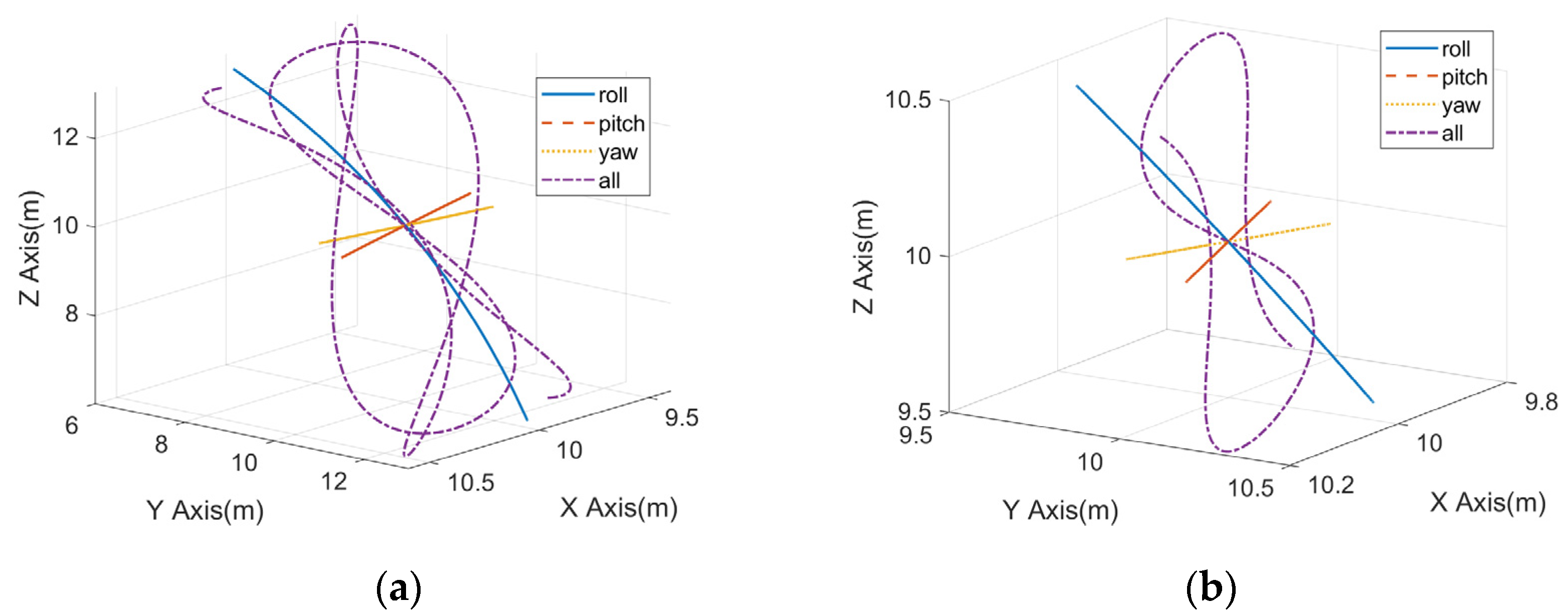
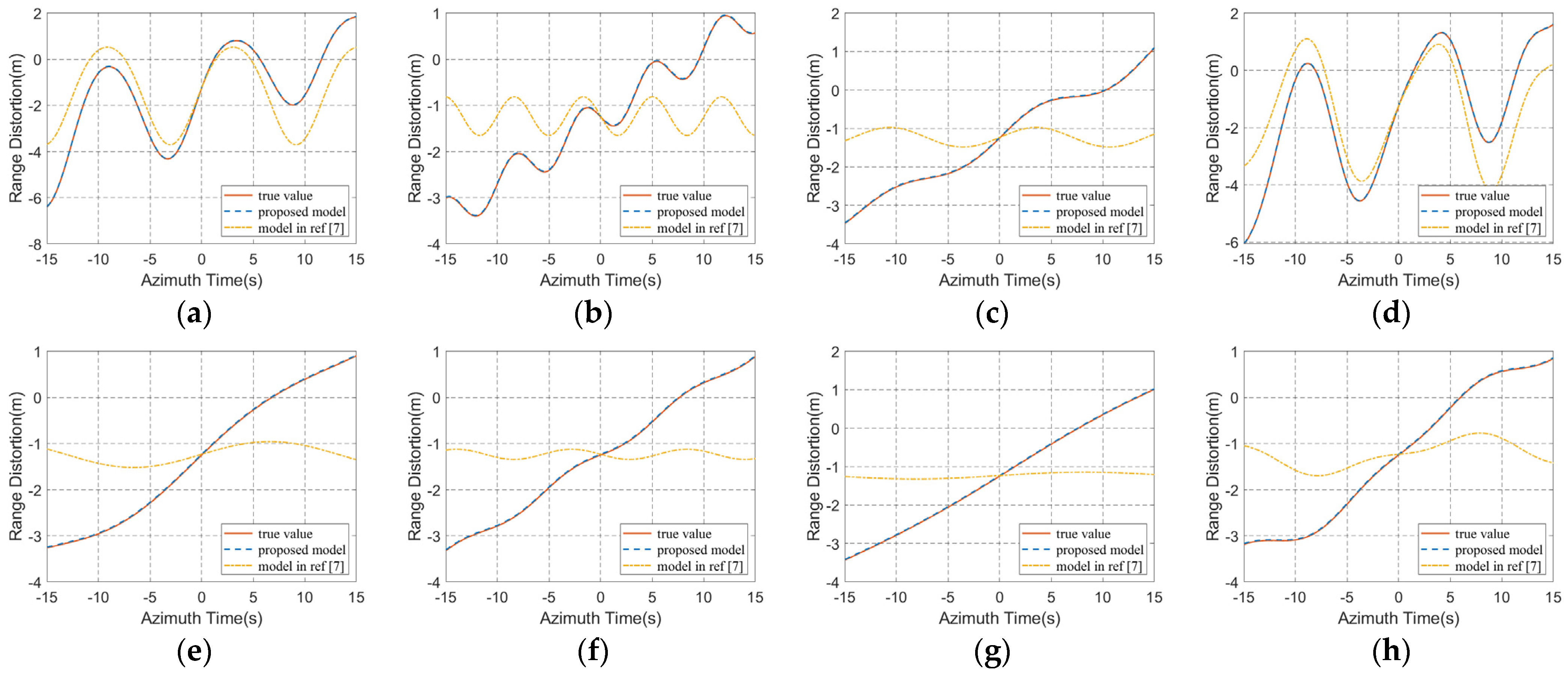
Supposing the initial phases of oscillation for both ships are zero, and only the angular oscillation exists during the observation time. The coordinate of point P in the ship-fixed coordinate system is (10 m, 10 m, 10 m), the system parameters are the same as those in Section 2.2, and the heading angle is 0°. Based on the oscillation parameters in Table 3, the trajectories of point P in the fixed space coordinate system during 30 s are shown in Figure 7. Then, the range models in this paper and reference [7] were used to calculate the distortions introduced by angular oscillations. The results are shown in Figure 8.
According to Figure 7, when only a certain angular oscillation exists, the trajectories of the target are relatively simple, which are typical circular arcs. Especially when the oscillation amplitudes are small, they can even be approximated as straight lines. However, the target trajectories become quite complicated when all the three-axis oscillations exist, as shown by the purple dot-dash lines in Figure 7. Since the target moves simultaneously in three degrees of freedom, its trajectories perform as the complex and nonperiodic spatial curves.
Figure 8 shows the comparison of range error calculated by range models in this paper and published literature. Since the change of projection direction caused by platform motions is not considered in [7], it will cause a large deviation which is mainly presented as the linear form. Besides, although the trajectory is relatively complex when all the three-axis oscillations exist, the range distortion caused by it is almost the same as that caused by only roll motion. Furthermore, this phenomenon is more obvious for destroyer. The above experiments proved that the proposed model has enough fitting accuracy for the target with angular oscillations.
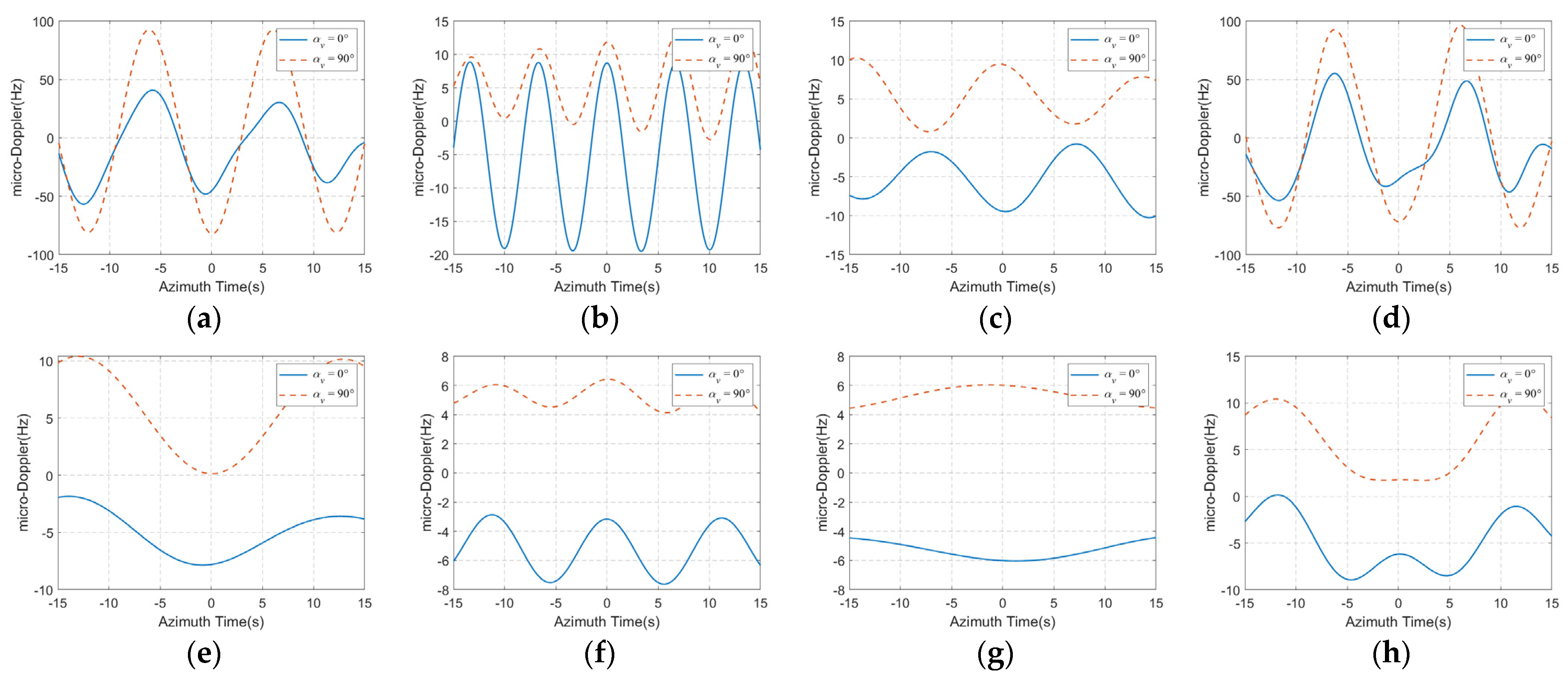
Then, we further simulated the micro-Doppler introduced by target angular oscillations. The results are shown in Figure 9, and two typical heading angles were considered in this experiment.
According to the above simulation results, the following conclusions can be drawn:
(1)
Under the given coordinate (10 m, 10 m, 10 m), the magnitude of the micro-Doppler introduced by the three angular oscillations is f d _ r o l l > f d _ p i t c h > f d _ y a w . The roll motion seems to be dominant when the ship is small, and this dominance will gradually weaken as the ship size increases.
(2)
When all the three angular oscillations exist at the same time, the micro-Doppler will become a relatively complex form, and the its periodicity will also be weakened, which may require more sinusoidal terms to better fit it.
(3)
With different heading angles, the micro-Doppler caused by angular oscillations has significant differences. According to Equation (33), the mean micro-Doppler introduced by roll motion is determined by 2 sin α v sin β 0 X p v a / ( λ H ) 2 L x _ 2 cos θ x 0 _ 2 J 0 ( B x ) / λ . Bring the simulation parameters into this formula, when the heading angle is 0° and 90°, the mean micro-Doppler of point P introduced by carrier rolling is –5.45 Hz and 5.45 Hz, respectively. The calculation results agree well with simulation results in Figure 9e, which proves the validity of the proposed model.

2.3.2. Multi-Frequency Angular Oscillation

In this subsection, a point target incorporating multi-frequency angular oscillation model is considered. Similar to the former analysis, we took the roll motion as an example to derivate the introduced range distortion and micro-Doppler.
By substituting the roll angle in Equation (2) into Equation (25), and ignoring the coefficient kt which is close to 1, the range distortion introduced by multi-frequency roll motion can be expressed as
R p _ r o l l ( t ) L x _ 1 cos [ i = 1 M x B x , i sin ( Ω x , i t + Ψ x , i ) + θ x 0 _ 1 ] + L x _ 2 cos [ i = 1 M x B x , i sin ( Ω x , i t + Ψ x , i ) + θ x 0 _ 2 ] t + L x 0 .
Then, according to the chain rule for composite functions derivation, the micro-Doppler introduced by roll motion can be written as
f d _ r o l l ( t ) 2 L x _ 1 λ i = 1 M x Ω x , i B x , i cos ( Ω x , i t + Ψ x , i ) sin [ i = 1 M x B x , i sin ( Ω x , i t + Ψ x , i ) + θ x 0 _ 1 ] + 2 L x _ 2 λ i = 1 M x Ω x , i B x , i cos ( Ω x , i t + Ψ x , i ) sin [ i = 1 M x B x , i sin ( Ω x , i t + Ψ x , i ) + θ x 0 _ 2 ] t 2 L x _ 2 λ cos [ i = 1 M x B x , i sin ( Ω x , i t + Ψ x , i ) + θ x 0 _ 2 ] + 2 λ sin α v sin β 0 X p v a H .
As shown in Equations (34) and (35), the expressions of range distortion and micro-Doppler become extremely complex because of the multi-frequency components. Since it is relatively difficult to directly analyze the angular oscillation with Mx frequency components, we took the dual-frequency roll motion as an example to make a tentative analysis. When Mx = 2, based on Jacobi–Anger expansion, the composite cosine in Equation (34) can be expanded as
cos [ i = 1 2 B x , i sin ( Ω x , i t + Ψ x , i ) + θ x 0 _ 1 ] = cos θ x 0 _ 1 { J 0 ( B x , 1 ) + 2 n = 1 J 2 n ( B x , 1 ) cos [ 2 n ( Ω x , 1 t + Ψ x , 1 ) ] } { J 0 ( B x , 2 ) + 2 n = 1 J 2 n ( B x , 2 ) cos [ 2 n ( Ω x , 2 t + Ψ x , 2 ) ] } cos θ x 0 _ 1 { 2 n = 1 J 2 n 1 ( B x , 1 ) sin [ ( 2 n 1 ) ( Ω x , 1 t + Ψ x , 1 ) ] } { 2 n = 1 J 2 n 1 ( B x , 2 ) sin [ ( 2 n 1 ) ( Ω x , 2 t + Ψ x , 2 ) ] } sin θ x 0 _ 1 { 2 n = 1 J 2 n 1 ( B x , 1 ) sin [ ( 2 n 1 ) ( Ω x , 1 t + Ψ x , 1 ) ] } { J 0 ( B x , 2 ) + 2 n = 1 J 2 n ( B x , 2 ) cos [ 2 n ( Ω x , 2 t + Ψ x , 2 ) ] } sin θ x 0 _ 1 { J 0 ( B x , 1 ) + 2 n = 1 J 2 n ( B x , 1 ) cos [ 2 n ( Ω x , 1 t + Ψ x , 1 ) ] } { 2 n = 1 J 2 n 1 ( B x , 2 ) sin [ ( 2 n 1 ) ( Ω x , 2 t + Ψ x , 2 ) ] } .
From Equation (36), the composite cosine with dual-frequency can be expressed as products of the sum of sinusoidal and co-sinusoidal functions. The cross-terms generated by multiplication operation have new angular frequencies, which can be expressed as p Ω x , 1 + q Ω x , 2   ( p , q N + ) . The expansion result of the composite sine in Equation (35) is similar to Equation (36).
With the increase of frequency components number associated with angular oscillation, the expression of the composite cosine will be shown as the products of more Jacobi–Anger expansion. This leads to range distortion and micro-Doppler need more sinusoidal functions to approximate, which undoubtedly increase the difficulty of accurate estimation of ship attitude.

3. The Effect of Oscillation on Imaging

Oscillations impart complicated nonlinear phase histories to radar echoes. They give rise to special SAR image characteristics, apart from the common defocusing and displacement which can also be induced by slowly moving targets. Therefore, it is necessary to give a specific analysis of their influence on SAR imaging.
From the analysis in Section 2, the phase distortions caused by oscillation can be approximated as the superposition of sinusoids and linear modulated sinusoids. Thus, based on the proposed rang models, the impact of target oscillation on imaging will be further analyzed in this part. According to the relationship between coherent processing interval (CPI) and oscillation period, this issue can be divided into two cases to discuss respectively. The first case is that the CPI is less than the oscillation period, which is more common in the actual signal processing, especially for large ships and low sea conditions. The Taylor expansion will be used to calculate the amplitude of different order phase error components. The second case is that CPI is greater than the oscillation period, which can be effectively analyzed by paired echo principle (PEP) [30,31]. In order to simplify the derivation, the following analysis is based on single-frequency oscillation. The system simulation parameters used in this section are listed in Table 4.

3.1. CPI Less Than the Oscillation Period

The phase distortion introduced by oscillation is nonperiodic in this case, which can be expanded by low-order Taylor expansion. It is well known that the phase errors of different orders have different impacts on SAR focusing, and the effects of different order phase errors on chirp signal matched filtering have been soundly investigated in [1,7,32,33,34]. The relationship between the phase error order and the effects on azimuth images are listed in Table 5.

3.1.1. Ship Linear Oscillation

According to Equation (14), when the coefficient kt is ignored, the range distortion introduced by linear oscillation can be concluded to the following form:
R p _ l i n e a r ( t ) A l [ C 0 v a sin β 0 cos β 1 cos α 1 t / H ] × sin ( ω l t + φ l ) = ( k l t + b l ) × sin ( ω l t + φ l ) .
According to the binomial expansion, the nth-order derivative of the linear modulated sinusoidal function in Equation (37) at t = 0 can be expressed as
g ( k l , b l , ω l , φ l , n ) = R p _ l i n e a r ( n ) ( 0 ) = n ω l n 1 k l sin ( φ l + n 1 2 π ) + ω l n b l sin ( φ l + n 2 π ) .
Then, perform the nth-order Taylor expansion of the phase distortion at t = 0:
R p _ l i n e a r ( t ) m = 0 n g ( k l , b l , ω l , φ l , m ) t m m   ! .
Based on the above formula, the phase error can be written as
ϕ p _ l i n e a r ( t ) = 4 π λ R p _ l i n e a r ( t ) 4 π λ m = 0 n g ( k l , b l , ω l , φ l , m ) t m m   ! = m = 0 n ϕ m ( t ) ,
where ϕ m ( t ) denotes the mth-order phase error component, λ is the wavelength.
Within the observation time T0, the maximum variation of each order phase error component can be expressed as follows:
max { ϕ m ( t ) } min { ϕ m ( t ) } = { 4 π λ m   ! g ( k l , b l , ω l , φ l , m ) ( T 0 2 ) m , m = 2 p 8 π λ m   ! g ( k l , b l , ω l , φ l , m ) ( T 0 2 ) m , m = 2 p + 1   p N .
Since the CPI is less than the oscillation period, the initial phase will have a great influence on the amplitude of phase error. Therefore, based on the parameters in Table 4, we further analyzed how the phase error changes with the initial phase. The oscillation period and amplitude are set as 30 s and 1 m, respectively. The maximum variation of phase error components from first-order to fourth-order are shown in Figure 10.
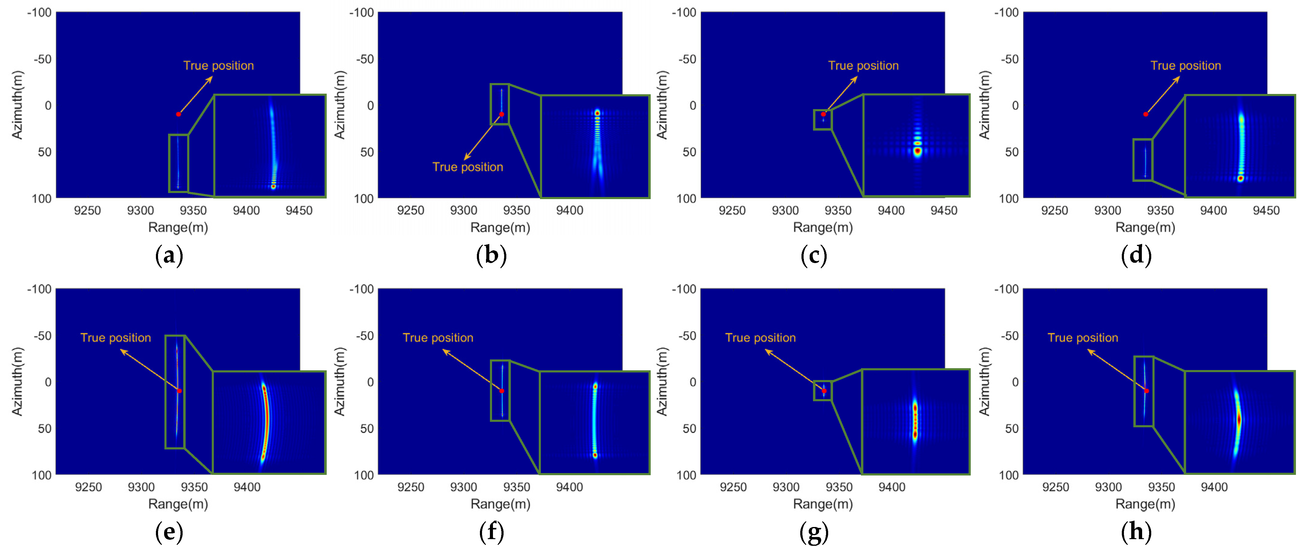
According to the simulation parameters, when the target oscillates along the range direction, bl is equal to Al and kl is approaching zero. When the target oscillates along the azimuth direction, bl is close to zero and kl is far less than Al. Therefore, the maximum variation of phase error components will present sinusoidal forms, as shown in Figure 10. To explicitly illustrate the impact of linear oscillation on imaging and verify the validity of the presented analysis, we generated the echoes of a point target with linear oscillation. The algorithm used for imaging is the classic Range Doppler (RD) algorithm, and the results are shown in Figure 11.
According to Figure 10a, when the target oscillates along the range direction, the odd-order phase errors are cosine functions and the even-order phase errors are sine functions. Thus, when the initial phase is 0, the echoes contain a large linear phase error (LPE) and a certain degree of cubic phase error (CPE). Therefore, the azimuth images will show the phenomenon of peak displacement and unbalanced sidelobes, as shown in Figure 11a. When the initial phase is π /2, the quadratic phase error (QPE) is dominant, so there will be heavily azimuth defocus in the focusing result, as shown in Figure 11b. When the target oscillates along the azimuth direction, the phase errors are relatively small, so the main effects on imaging are presented as slight displacement and defocus, as shown in Figure 11c,d.

3.1.2. Ship Angular Oscillation

As shown in Equation (32), the range distortion introduced by roll motion can be expressed as the superposition of multiple-frequency sinusoids, and some of the sinusoids are linear modulated. The range distortion can be rewritten as
R p _ r o l l ( t ) i = 1 ( k r 1 , i t + b r 1 , i ) cos [ 2 i ( Ω x t + Ψ x ) ] + i = 1 ( k r 2 , i t + b r 2 , i ) sin [ ( 2 i 1 ) ( Ω x t + Ψ x ) ] + L 0 _ n e w ,
where
k r 1 , i = 2 J 2 i ( B x ) L x _ 2 cos θ x 0 _ 2 b r 1 = 2 J 2 i ( B x ) L x _ 1 cos θ x 0 _ 1 k r 2 = 2 J 2 i 1 ( B x ) L x _ 2 sin θ x 0 _ 2 b r 1 = 2 J 2 i 1 ( B x ) L x _ 1 sin θ x 0 _ 1 L 0 _ n e w = L x 0 + ( L x _ 1 cos θ x 0 _ 1 + L x _ 2 cos θ x 0 _ 2 t ) J 0 ( B x ) .
Then, based on Equation (38), the nth-order derivative of R p _ r o l l ( 0 ) can be obtained:
R p _ r o l l ( n ) ( 0 ) = i = 1 g ( k r 1 , i , b r 1 , i , 2 i Ω x , π 2 2 i Ψ x , n ) + i = 1 g ( k r 2 , i , b r 2 , i , ( 2 i 1 ) Ω x , ( 2 i 1 ) Ψ x , n ) + L 0 _ n e w ( n ) .
Then, within the observation time T0, the maximum variation of each order phase error component can be expressed as follows:
max { ϕ m ( t ) } min { ϕ m ( t ) } = { 4 π λ m   ! [ i = 1 g ( k r 1 , i , b r 1 , i , 2 i Ω x , π 2 2 i Ψ x , n ) + i = 1 g ( k r 2 , i , b r 2 , i , ( 2 i 1 ) Ω x , ( 2 i 1 ) Ψ x , n ) + L 0 _ n e w ( m ) ] ( T 0 2 ) m , m = 2 p 8 π λ m   ! [ i = 1 g ( k r 1 , i , b r 1 , i , 2 i Ω x , π 2 2 i Ψ x , n ) + i = 1 g ( k r 2 , i , b r 2 , i , ( 2 i 1 ) Ω x , ( 2 i 1 ) Ψ x , n ) + L 0 _ n e w ( m ) ] ( T 0 2 ) m , m = 2 p + 1   p N .
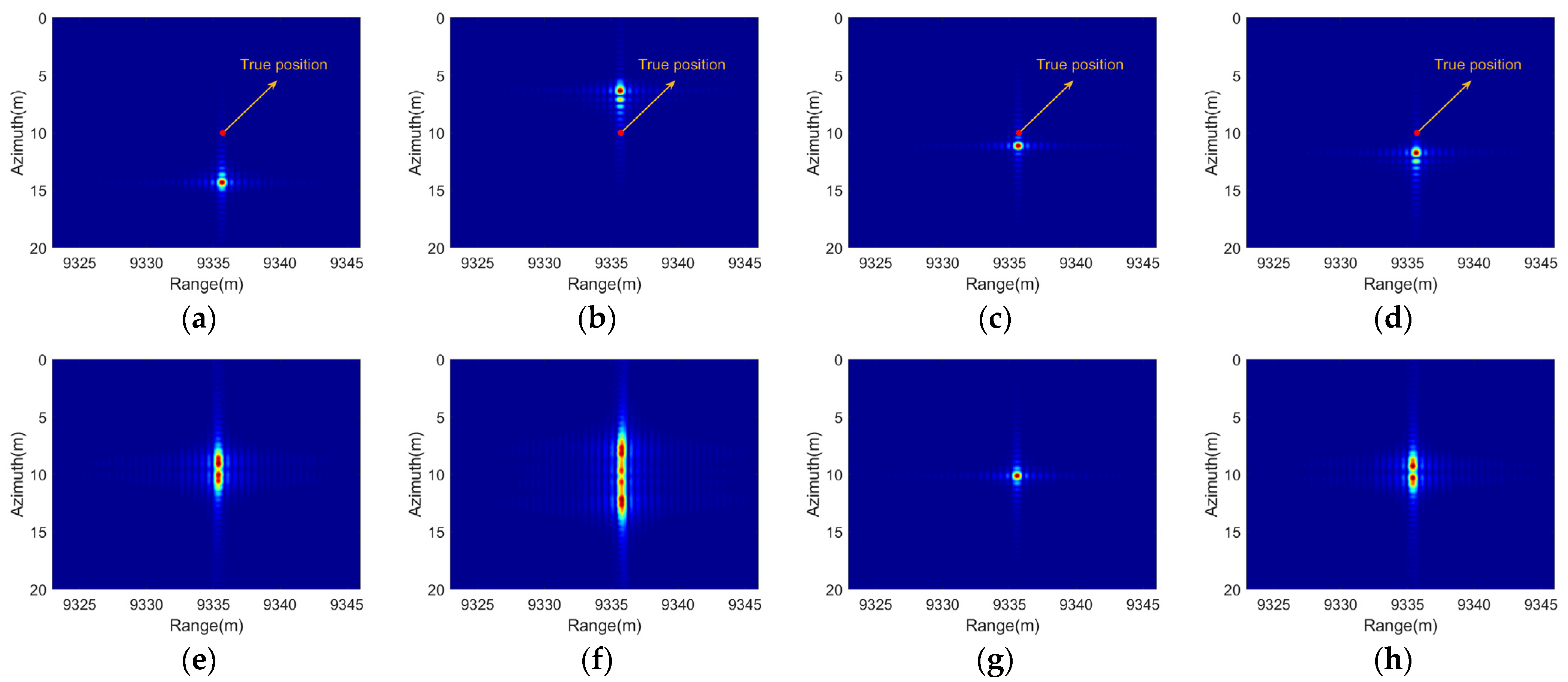
The results are similar when there are only pitch and yaw motions. Based on the oscillation parameters in Table 3 and the system parameters in Table 4, we simulated how the maximum variation of each order phase error components change with the initial phase. The results about the destroyer oscillation are shown in Figure 12. Then, the initial phases 0 and π /2 are chosen for imaging simulation. The coordinate of the point target is (10 m, 10 m, 10 m) in the ship-fixed coordinate system, the imaging results are shown in Figure 13.
According to Figure 12, when initial phases are zero, the LPEs caused by these four oscillations have different magnitudes, which will lead to the varying degrees of peak displacement in the azimuth, as shown in the first row in Figure 13. Meanwhile, roll motion will introduce obvious QPE, which will cause the azimuth defocus, as shown in Figure 13a,d. The CPE will cause the unbalanced sidelobes of the impulse response, as shown in Figure 13b,c. When the initial phases are π /2, the LPEs and CPEs of the four types of oscillations are close to zero, so the imaging results are centrosymmetric and located in the true position, the defocusing is mainly determined by the magnitude of the QPEs and quartic phase errors.
Then, the motion parameters of the carrier in sea-state 5 were also used to analyze the effects of angular oscillation. The maximum variations of each order phase error component and the imaging results are shown in Figure 14 and Figure 15 respectively. Compared with the oscillation parameters of the destroyer, the carrier’s oscillations have smaller amplitudes and longer periods, so their impact on imaging is relatively slight.

3.2. CPI Greater Than the Oscillation Period

In this case, since the phase error contains periodic sinusoidal terms, it cannot be approximated by lower-order expansion. As a series expansion method, the Bessel function was used to expand the phase error, then the impacts of oscillation on imaging can be further analyzed. According to [29], the following expansion can be obtained:
e j b sin x = n = J n ( b ) e j n x = J 0 ( b ) + n = 1 J n ( b ) [ e j n x + ( 1 ) n e j n x ] ,
where J n ( ) denotes the nth Bessel function of the first kind.

3.2.1. Ship Linear Oscillation

The phase error introduced by ship linear oscillation can be rewritten as
ϕ p _ l i n e a r ( t ) = 4 π [ b l sin ( ω l t + φ l ) + k l t sin ( ω l t + φ l ) ] / λ .
First, the sinusoidal phase error exp ( j 4 π b l sin ( ω l t + φ l ) / λ ) is considered. According to Equation (46), the sinusoidal phase error can be expanded as
e j 4 π b l sin ( ω l t + φ l ) / λ = J 0 ( 4 π b l / λ ) + n = 1 J n ( 4 π b l / λ ) [ e j n φ l e j n ω l t + ( 1 ) n e j n φ l e j n ω l t ] .
Based on the shift property of Fourier Transform, the exponent terms in Equation (48) will produce paired echoes on both sides of the impulse response, as shown in Figure 16a. Moreover, the relative amplitude of the nth paired echoes is J n ( 4 π b l / λ ) / J 0 ( 4 π b l / λ ) . The time interval between adjacent echoes is Δ t = ω l / ( 2 π K ) , where K denotes the frequency modulation ratio of the chirp signal. As the oscillation period increase, the interval between adjacent echoes will gradually decrease and the echoes energy will be more concentrated in the azimuth.
Then, take the linear modulated sinusoidal phase error into account. It should be noted that the linear coefficient kl is proportional to va/H, so its value will be far less than 1 and its impact can be ignored in most scenarios except for bl = 0. In order to use the Bessel function to analyze this linear modulated sinusoidal phase error, we rewrite this term as follows:
k l t sin ( ω l t + φ l ) sin ( k l t ) sin ( ω l t + φ l ) = 1 2 [ cos ( ( ω l k l ) t + φ l ) cos ( ( ω l + k l ) t + φ l ) ] .
Therefore, the linear modulated sinusoidal phase error can be divided into two parts:
e j 2 π λ cos ( ( ω l k l ) t + φ l ) e j 2 π λ sin ( ( ω l k l ) t + φ l + π 2 ) = J 0 ( 2 π / λ ) + n = 1 J n ( 2 π / λ ) [ e j n ( φ l + π / 2 ) e j n ( ω l k l ) t + ( 1 ) n e j n ( φ l + π / 2 ) e j n ( ω l k l ) t ] ,
e j 2 π λ cos ( ( ω l + k l ) t + φ l ) e j 2 π λ sin ( ( ω l + k l ) t + φ l + π 2 ) = J 0 ( 2 π / λ ) + n = 1 J n ( 2 π / λ ) [ e j n ( φ l + π / 2 ) e j n ( ω l + k l ) t + ( 1 ) n e j n ( φ l + π / 2 ) e j n ( ω l + k l ) t ] .
From the above formulas, since the kl is small, the linear modulated sinusoidal phase error will produce two symmetrical echoes on both sides of n Δ t , and the echoes will decrease rapidly with the increase of t, as shown in Figure 16b.
Then, in order to verify the presented conclusions, we conducted several imaging experiments based on the parameters in Table 4. The oscillation period is one second, and the linear oscillation amplitude is set as 1 m and 0.05 m, which are larger and smaller than the range unit, respectively. The imaging results are shown in Figure 17.
In the case of the target oscillating along the range direction, the phase distortion introduced by linear oscillation is approximately sinusoidal function. According to Equation (37), the sinusoidal phase error will produce paired echoes on both sides of the impulse response, as shown in Figure 17a,b. Besides, if the oscillation amplitude is larger than the range unit, the range cell migration will result in the energy being distributed across multiple range gates, as shown in Figure 17a.
In the case of the target oscillating along the azimuth direction, the phase distortion introduced by target motion is linear modulated sinusoidal form with relatively small amplitude. If the oscillation amplitude is large enough, it will also produce symmetrical echoes on both sides, and the echoes will decrease rapidly with the increase of azimuth time, as shown in Figure 17c.

3.2.2. Ship Angular Oscillation

The scenarios of CPI exceeding the ship’s angular oscillation periods are not common, only when the radar platform moves very slowly or the platform runs in an extremely high orbit. There is a simple analysis of this situation, ignoring the residual linear polynomial of Equation (42), the phase error introduced by roll motion can be rewritten as follows:
ϕ p _ r o l l ( t ) 4 π λ [ i = 1 b r 1 , i cos [ 2 i ( Ω x t + Ψ x ) ] + i = 1 b r 2 , i sin [ ( 2 i 1 ) ( Ω x t + Ψ x ) ] ] + 4 π λ [ i = 1 k r 1 , i t cos [ 2 i ( Ω x t + Ψ x ) ] + i = 1 k r 2 , i t sin [ ( 2 i 1 ) ( Ω x t + Ψ x ) ] ] .
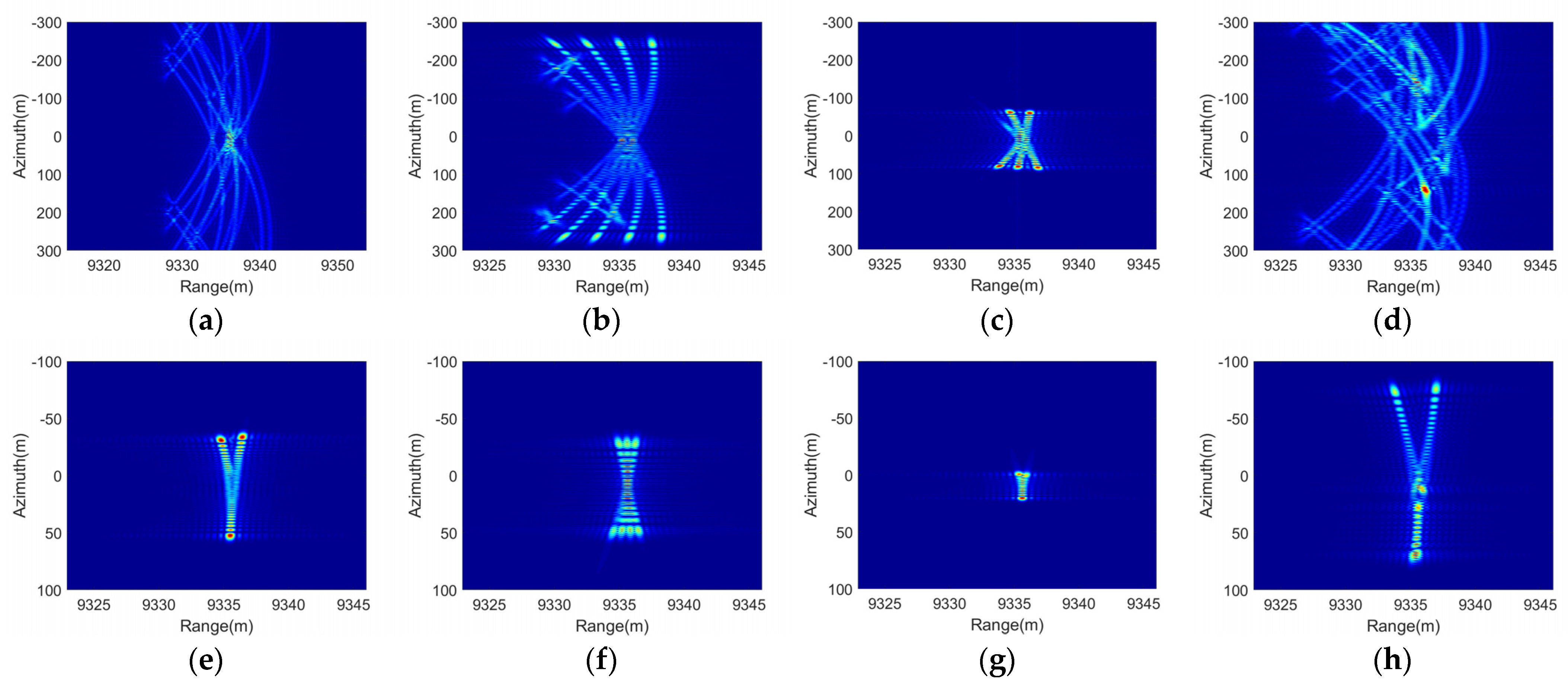
According to Equation (48), each sinusoidal phase error will produce infinitely symmetric echoes after Fourier Transform. Furthermore, Equation (52) indicates that this process will be repeated at least four times, so this multi-sinusoidal phase error will cause the echo energy to disperse to nearby azimuth units. In addition, the angular oscillation usually leads to the rang cell migration of the target, which also causes the dispersion of the energy in the range direction. Therefore, the final imaging results distorted by single angular oscillation are often disordered lines, which are symmetric in the azimuth direction. However, if all the three-axis oscillations exist simultaneously, the disorder will intensify and the symmetry will gradually disappear.
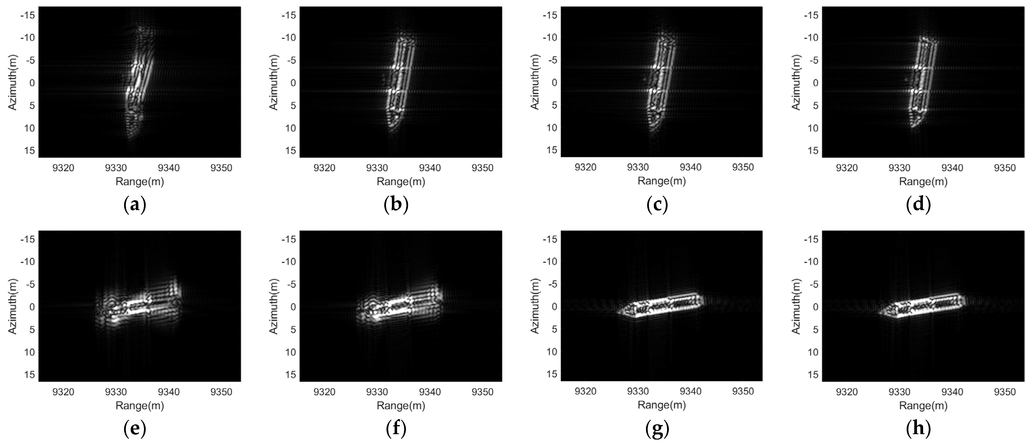
In order to make the CPI larger than the oscillation periods in Table 3, we changed the flight speed of the platform to 14 m/s, CPI will be extended to 37.3 s, the remaining system parameters are the same as in Table 4. The imaging results distorted by four kinds of oscillation are shown in Figure 18.
According to Figure 18, when the CPI is longer than oscillation periods, the range cell migration and periodic phase error caused by ship angular motions will lead to serious defocus in both range and azimuth direction. Moreover, since the phase error introduced by angular oscillation presents a multi-sinusoidal form, the defocused energy will be approximately evenly distributed in the azimuth direction, which resulting in the disordered lines. When the oscillation periods are close to CPI, the periodicity of the phase error is weakening. Therefore, the imaging results will be presented as line segments, as shown in Figure 18g, which is similar to the images distorted by high-order phase errors.

4. Measured Data and Experimental Results

In order to further analyze the influence of ship oscillation and verify the validity of the range model proposed in this paper, a field campaign was carried out to obtain the real attitude data of the ship. It should be noted that the following experiments are mainly about the ship angular oscillation, while linear oscillation is hard to be measured by our experimental equipment.
Based on the measured ship attitude data, a set of semi-physical simulations were carried out to illustrate the impact of angular oscillation on ship imaging. Then, we verified the conclusion that the oscillatory angle can be approximated as multi-sinusoidal in a certain time. Finally, a phase compensation experiment was conducted to verify the validity of the proposed range model.

4.1. Measured Data of Ship Attitude

4.1.1. Experimental Condition

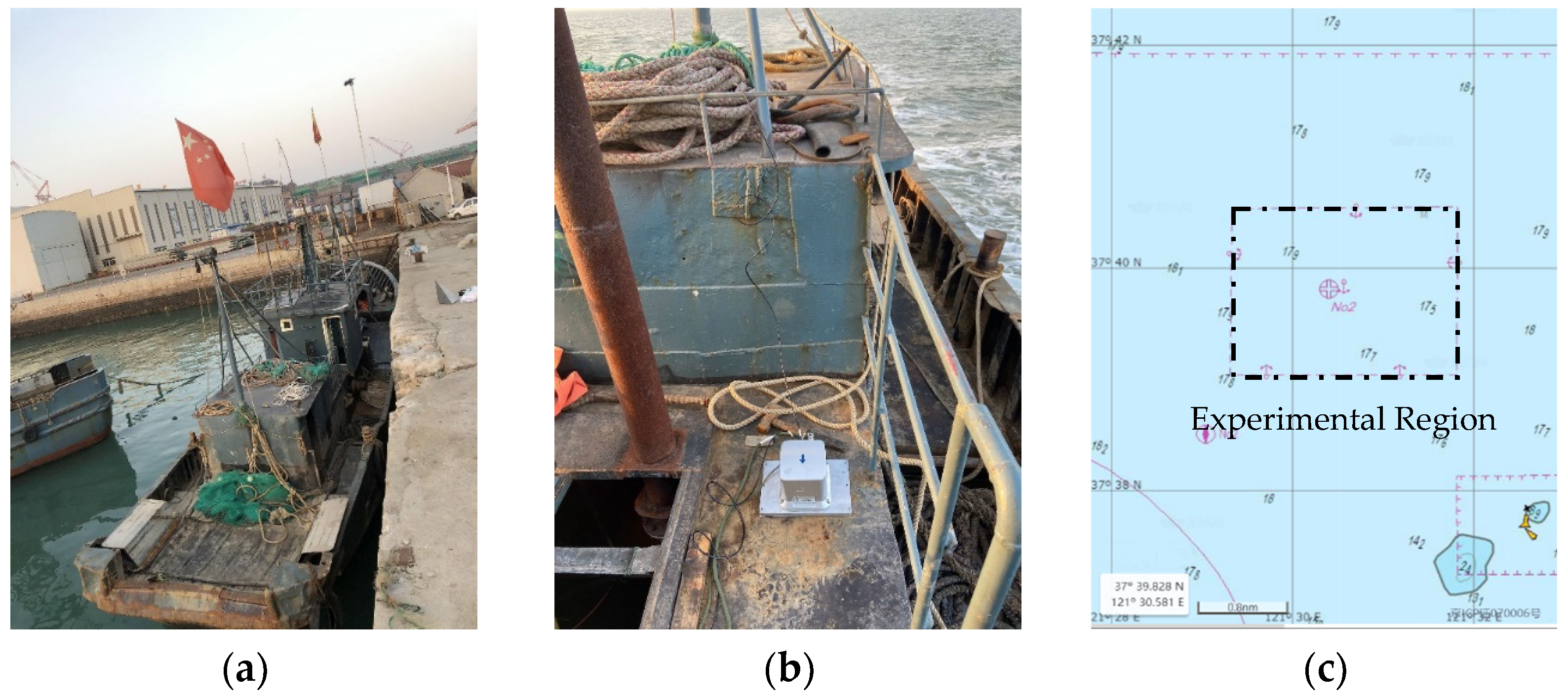
The field campaign was carried out on 28 December 2019, and Figure 19 shows the equipment and condition of this test. Figure 19a shows the experimental vessel, which is a fishing boat with 20 m in length and 3 m in width. Figure 19b shows the appearance of the inertial measurement unit (IMU), which was fixed in the middle of the boat. Furthermore, there were two antennas placed tandem on the longitudinal axis of the ship, the signal source can be selected from the Global Navigation Satellite System (GNSS) or BeiDou Navigation Satellite System (BDS). Based on this instrument, we can measure the attitude angles, position, and speed of the ship. When the satellite signal quality is excellent and the baseline length is greater than two meters, the measurement accuracy of heading angle, attitude angles (roll and pitch), and position can reach 0.1 degrees, 0.05 degrees, and 3 m, respectively. Figure 19c shows the experimental region of this test, which is around an anchorage near to Yantai Port. The center coordinate of this anchorage is 37°39.828N, 121°30.581E.
Table 6 summarizes the sea state at the beginning and the end of data acquisition, all the marine environment data was obtained from Aeronautical Information Services (AIS). According to Table 6, the sea state during the experiment was level 3, which means there are slight waves and the ships may feel slightly bumpy.

4.1.2. Measured Data

The data collection was mainly done by a laptop connected to the IMU. When the IMU is powered on, it will send the measured motion and attitude data to the computer via the serial port in real time, with a recording interval of 0.1 s. It should be noted that the attitude data output by the IMU is the real-time heading, pitch, and roll angles of the ship, where the heading angle is the sum of the ship’s navigating angle and yaw angle.
The process of ship movement measurement test can be briefly described as follows:
(1)
Set off from the harbor to experimental region;
(2)
Turned off the power and allowed the ship to drift along the current, then recorded the attitude data of the ship, this process lasted about 1.5 h;
(3)
Anchored the ship to the center of the anchorage, then recorded the attitude data of the ship, this process continued for 2 h;
(4)
Weighed anchor and drove the ship back-and-forth along a specific route, recorded the attitude data of the ship during this process, this step took about 40 min;
(5)
Back to the harbor.
In the above processes, the ship motion and attitude data were all recorded. Part of the measured ship motion data in processes (2), (3), and (4) are shown in Figure 20.
The variation range and standard deviation of the measured attitude angles in the three states are listed in Table 7. In the unanchored state, the ship is affected by the sea wind and waves without any traction, so the variation range and the stand deviation are both the largest (the heading angle in the navigating state was controlled artificially, so there was a larger dynamic range).

4.2. Experiments Based on the Measured Attitude Data

The experiments in this subsection are mainly based on the measured attitude data, including (1) generating the semi-physical echoes of the oscillatory ship to analyze the impact of oscillation on imaging; (2) compensating the phase distortion based on the proposed range model to verify its accuracy.

4.2.1. Focusing Results of the Oscillatory Ship

The focusing results of the oscillatory ship based on the measured attitude data are given in this subsection. The established ship point-array model is shown in Figure 21, the basic shape and size of the ship were derived from the experimental vessel in the field campaign. The length, width, and height of the ship model is 20 m, 3 m, and 4 m, respectively. This model consists of 278 point scatters, the interval between adjacent scatters is about 0.5 m, and the reflection coefficient of each point is equal. Markers A, B, and C represent the scatters at the stern, mast, and bow, respectively.
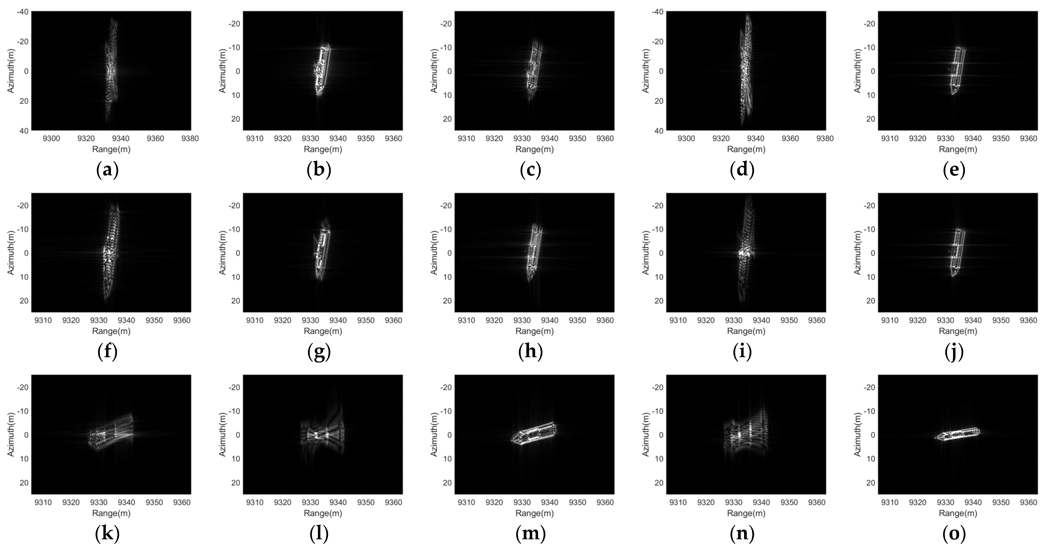
Based on the presented ship model and the measured ship attitude data, the semi-physical echoes of the oscillatory ship in different states can be generated. If the point scatters are well focused, the imaging results will be the projection of the ship in the direction of RLOS, which will change with the relative position between the platform and the ship target. The simulation system parameters are listed in Table 6. The ship attitude angles used for imaging are shown in Figure 22, and the focusing results of the oscillatory ship in different states are shown in Figure 23.
It can be seen that the effect of oscillation on ship imaging would be affected by many factors. For example, the defocus of the ship in Figure 23l is more serious than that in Figure 23b,g, since the heading angle was about 180 degrees in the navigating state, the displacement caused by pitch motion will be more projected to the radial direction. Besides, compared to the images in the first row and the second row, the anchored ship is less defocused with the same heading angle.
Furthermore, ship angular oscillation can cause some special defocusing phenomena. Since the ship rotates around the centroid, the phase error caused by oscillation is usually maximum at both ends and minimum at the center. Therefore, when the linear phase error is dominant, the imaging result will be a ship stretched in the azimuth direction, as shown in Figure 23f,m. When the quadratic phase error is dominant, the targets at different range cells will be defocused to different length of line segments, so the imaging results are ‘X’ shaped, as shown in Figure 23a,l.

4.2.2. Phase Compensation Based on the Proposed Range Model

According to the simulation results in Section 2.3, if the ship attitude angles can be approximated by single-frequency or multiple-frequency sinusoidal functions during CPI, the range error caused by angular oscillation can be accurately calculated through the proposed range model. Thus, based on the measured attitude angles, this subsection made some tentative research on the phase compensation and refocus of the oscillatory ship, which has two main purpose:
(1)
verifying the accuracy of the proposed range model for ship angular oscillation;
(2)
exploring the feasibility of phase compensation by fitting ship attitude angles with multi-frequency oscillation model.
First, we explored the feasibility and the application scenarios of approximating the ship attitude angles by multiple sinusoidal functions based on the measured ship attitude data. We selected 20 s of data in the three states, and all of them show irregular fluctuations, as shown in Figure 24.
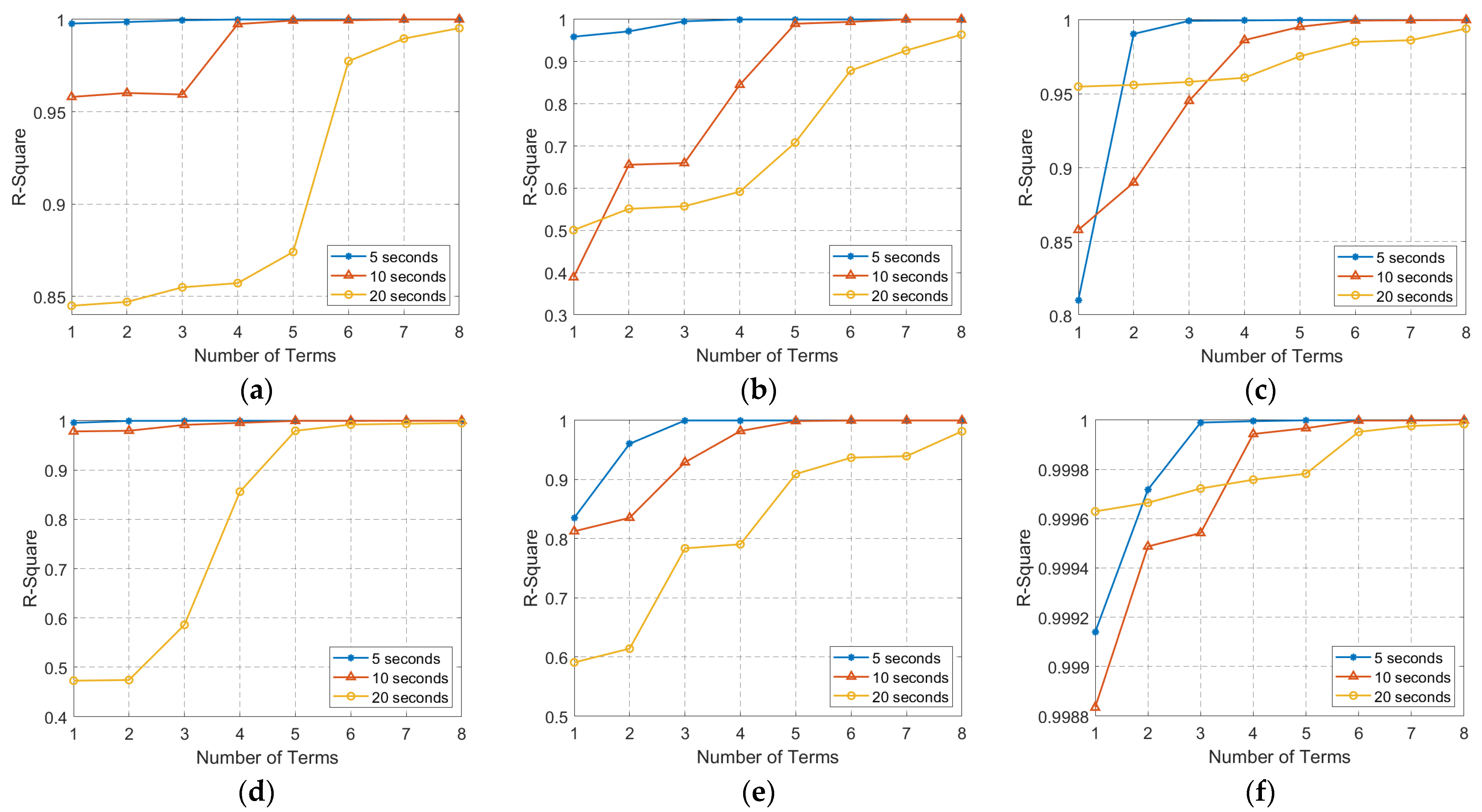
Then, the attitude angles were fitted by 1~8 terms of Fourier series based on the least square principle, the duration of the data was selected as 5 s, 10 s, and 20 s, respectively. The fitting results are shown in Figure 25. Since the fitting results of unanchored state and anchored state are similar, here only shows the results of the former.
As shown in Figure 25, when the observation time is five seconds, the Fourier series fitting method had a high fitting accuracy only using several sine and cosine terms. In particular, the roll motion, as the main component of angular oscillation, can be approximately expressed as a sine within the duration of five seconds. With the increase of the observation time, the number of sinusoidal terms required for accurate fitting is gradually rising. However, if the observation time is too long, such as 20 s, since the randomness of the sea breeze and waves, it is difficult to exactly describe the attitude angles even using eight sinusoidal terms. Through the above simulation and analysis, within a few seconds, it is reasonable to approximate the ship attitude angles as the superposition of multiple sinusoidal functions.
Next, we used 1~4 sinusoidal functions to fit the attitude angles used for imaging in Section 4.2.1, and then compensated the phase errors of Point A, B, and C according to the range model proposed in this paper. The residual phase errors of these three points in the unanchored state and navigating state are shown in Figure 26.
Finally, the attitude angles obtained by 1~4 sinusoidal fitting were used for compensating the phase error of oscillatory ship. The refocusing results are shown in Figure 27. The imaging results showed that it is feasible to use several sinusoidal functions to fit the ship attitude angles for phase compensation.
However, the phase compensation method based on the proposed range model is only theoretically feasible at present, there are still many practical problems. The ship attitude parameters are generally unknown in practice, so the phase compensation in this subsection was conducted based on the assumption that we can get optimal attitude angles estimation by parameters search methods, such as grid search and random search. Nevertheless, it is foreseeable that these search methods have heavily computation burden because of the numerous search parameters, especially for multi-frequency oscillation. The searching process needs further optimization to achieve efficient phase compensation for oscillating ship.

5. Conclusions

Oscillatory motions widely exist on the sea-surface targets, which significantly increases the difficulty of precise focusing. In this paper, we proposed the accurate range models for ship linear oscillation and angular oscillation, and the superiority was verified by comparing them with the models described in published literature. Then, we further analyzed the effect of oscillation on imaging. In the case of CPI less than the oscillation period, we gave the expressions of the maximum errors of each order phase component based on Taylor expansion. Furthermore, the impact of the oscillation initial phase was further analyzed. In the case of CPI greater than the oscillation period, the Bessel function was employed to expand the periodic sinusoidal phase error. Typical defocusing results are symmetric ghost points or disordered lines. Finally, based on the measured ship attitude data, we generated the semi-physical echoes of the oscillatory ship to analyze the impact of oscillation on imaging. In most scenarios, the roll motion has the greatest amplitude, but the influence on imaging would be affected by many factors, such as the heading angle, ship state, and selection of CPI. In addition, based on the proposed range model, we also made some tentative on the phase compensation method by fitting ship attitude angles with multiple sinusoidal functions. This article has tried to reveal the underlying problems of ship imaging with respect to complicated oscillation, which could provide some perspectives to the high-resolution imaging technique development of ships in the future.

Author Contributions

Conceptualization, B.Z. and X.Q.; methodology, B.Z.; software, B.Z.; validation, B.Z.; formal analysis, B.Z. and J.Z.; investigation, B.Z. and J.Z.; resources, X.Q.; data curation, B.Z.; writing—original draft preparation, B.Z.; writing—review and editing, H.Z.; visualization, H.Z.; supervision, X.Q.; project administration, X.Q.; funding acquisition, X.Q. All authors have read and agreed to the published version of the manuscript.

Funding

This research was funded in part by the National Key Research and Development Program of China under Grant Y7BD160194.

Acknowledgments

The authors would like to thank all reviewers and editors for their comments on this paper.

Conflicts of Interest

The authors declare no conflict of interest.

Appendix A. The Specific Derivation Result of Range Distortion When Roll, Pitch, and Yaw Motion All Exist

In Section 2.3.1, the range distortions introduced by roll, pitch, and yaw motion were given, respectively. When all the three angular oscillations exist, the range expression will become extremely complicated, and the specific derivation results were shown here.
Considering the existence of all the three angular oscillations, the rotation matrix in Equation (4) can be rewritten as
R o t 1 ( θ x , θ y , θ z ) = [ cos θ y cos θ z cos θ y sin θ z sin θ y sin θ x sin θ y cos θ z + cos θ x sin θ z sin θ x sin θ y sin θ z + cos θ x cos θ z sin θ x cos θ y cos θ x sin θ y cos θ z + sin θ x sin θ z cos θ x sin θ y sin θ z + sin θ x cos θ z cos θ x cos θ y ] .
By substituting the Equation (A1) into Equation (24), the range distortions introduced by all angular oscillation can be expressed as
R p _ a l l ( t ) = k t [ cos β 0 A 11 + sin β 0 A 12 + sin β 0 v a t H A 13 cos β 0 A 21 + sin β 0 A 22 + sin β 0 v a t H A 23 cos β 0 A 31 + sin β 0 A 32 + sin β 0 v a t H A 33 ] T [ X p Y p Z p ] ,
where
A 11 = sin ( α v α 0 ) cos θ y cos θ z cos ( α v α 0 ) sin θ x sin θ y cos θ z cos ( α v α 0 ) cos θ x sin θ z ,
A 12 = cos θ x sin θ y cos θ z + sin θ x sin θ z ,
A 13 = sin α v cos θ y cos θ z + cos α v sin θ x sin θ y cos θ z + cos α v cos θ x sin θ z ,
A 21 = sin ( α v α 0 ) cos θ y sin θ z + cos ( α v α 0 ) sin θ x sin θ y sin θ z cos ( α v α 0 ) cos θ x cos θ z ,
A 22 = cos θ x sin θ y sin θ z + sin θ x cos θ z ,
A 23 = sin α v cos θ y sin θ z cos α v sin θ x sin θ y cos θ z + cos α v cos θ x sin θ z ,
A 31 = sin ( α v α 0 ) sin θ y + cos ( α v α 0 ) sin θ x cos θ y ,
A 32 = cos θ x cos θ y ,
A 33 = sin α v sin θ y cos α v sin θ x cos θ y .

Appendix B. The Range Distortion and micro-Doppler Introduced by Pitch and Yaw

In this part, the specific derivation results of the range distortion and micro-Doppler introduced by pitch and yaw are given. The results are similar when there is only roll motion and pitch motion, but are a little different for yaw motion, the specific derivation results are shown as follows.
First, we made the derivation for pitch motion. Based on the auxiliary angle formula, Equation (26) can be rewritten as
R p _ p i t c h ( t ) = k t sin ( α v α 0 ) cos β 0 ( Z p sin θ y + X p cos θ y ) + k t sin β 0 ( Z p cos θ y X p sin θ y ) k t sin β 0 [ sin α v ( Z p sin θ y + X p cos θ y ) cos α v Y p ] v a t / H k t cos ( α v α 0 ) cos β 0 Y p = k t { L y _ 1 cos [ B y sin ( Ω y t + Ψ y ) + θ y 0 _ 1 ] + L y _ 2 cos [ B y sin ( Ω y t + Ψ y ) + θ y 0 _ 2 ] t + L y 0 } ,
L y _ 1 = X p 2 + Z p 2 sin 2 ( α v α 0 ) cos 2 β 0 + sin 2 β 0 L y _ 2 = X p 2 + Z p 2 sin α v sin β 0 v a / H θ y 0 _ 1 = arctan sin ( α v α 0 ) cos β 0 Z p sin β 0 X p sin ( α v α 0 ) cos β 0 X p + sin β 0 Z p θ y 0 _ 2 = arctan Z p X p L y 0 = cos α v sin β 0 Y p v a t H cos ( α v α 0 ) cos β 0 Y p ,
where L y _ 1 and L y _ 1 , θ y 0 _ 1 and θ y 0 _ 2 are the effective amplitude and initial phase of the composite cosine, respectively. L y 0 is the residual linear term after merging.
Since the range distortions introduced by pitch motion and roll motion are similar, the micro-Doppler introduced by pitch motion can be referred to Equation (33), which will not be repeated here.
Next, we made the derivation for yaw motion. Equation (27) can be rewritten as
R p _ y a w ( t ) = k t cos β 0 ( X p sin ( θ z α v + α 0 ) Y p cos ( θ z α v + α 0 ) ) + k t sin β 0 [ X p sin ( θ z α v ) + Y p cos ( θ z α v ) ] v a t / H + k t sin β 0 Z p = k t { L z _ 1 cos [ B z sin ( Ω z t + Ψ z ) + θ z 0 _ 1 ] + L z _ 2 cos [ B z sin ( Ω z t + Ψ z ) + θ z 0 _ 2 ] t + L z 0 } ,
L z _ 1 = X p 2 + Y p 2 cos β 0 L z _ 2 = X p 2 + Y p 2 sin β 0 v a / H θ z 0 _ 1 = α 0 α v + arctan X p Y p θ z 0 _ 2 = α v + arctan X p Y p L z 0 = sin β 0 Z p ,
where L z _ 1 and L z _ 1 , θ z 0 _ 1 and θ z 0 _ 2 are the effective amplitude and initial phase of the composite cosine, respectively. L z 0 is the residual constant term after merging.
The expression of range distortion introduced by yaw motion is a little different with the former results, but is can still be simplified by angle auxiliary formula. Then, based on Jacobi-Anger expansion, Equation (A14) can be rewritten as
R p _ y a w ( t ) ( L z _ 1 cos θ z 0 _ 1 + L z _ 2 cos θ z 0 _ 2 t ) { J 0 ( B z ) + 2 n = 1 J 2 n ( B z ) cos [ 2 n ( Ω z t + Ψ z ) ] } 2 ( L z _ 1 sin θ z 0 _ 1 + L z _ 2 sin θ z 0 _ 2 t ) { 2 n = 1 J 2 n 1 ( B z ) sin [ ( 2 n 1 ) ( Ω z t + Ψ z ) ] } + L z 0 .
Then, the micro-Doppler caused by yaw motion can be expressed as
f d _ y a w ( t ) 2 λ L z _ 2 cos θ z 0 _ 2 J 0 ( B z ) 4 λ L z _ 2 cos θ z 0 _ 2 n = 1 J 2 n ( B z ) cos [ 2 n ( Ω z t + Ψ z ) ] + 4 Ω z λ ( L z _ 1 cos θ z 0 _ 1 + L z _ 2 cos θ z 0 _ 2 t ) n = 1 2 n J 2 n ( B z ) sin [ 2 n ( Ω z t + Ψ z ) ] + 4 λ L z _ 2 sin θ z 0 _ 2 n = 1 J 2 n 1 ( B z ) sin [ ( 2 n 1 ) ( Ω z t + Ψ z ) ] + 4 Ω z λ ( L z _ 1 sin θ z 0 _ 1 + L z _ 2 sin θ z 0 _ 2 t ) n = 1 ( 2 n 1 ) J 2 n 1 ( B z ) cos [ ( 2 n 1 ) ( Ω z t + Ψ z ) ] .

References

  1. Cumming, I.; Wong, F. Digital Processing of Synthetic Aperture Radar Data: Algorithms and Implementation; Artech House: Boston, MA, USA, 2005; pp. 113–168. [Google Scholar]
  2. Vessel Motion Calculator. Available online: https://calqlata.com/productpages/00059-help.html (accessed on 16 February 2021).
  3. Yao, G.; Xie, J.; Huang, W. Ocean Surface Cross Section for Bistatic HF Radar Incorporating a Six DOF Oscillation Motion Model. Remote Sens. 2019, 11, 2738. [Google Scholar] [CrossRef] [Green Version]
  4. Yao, G.; Xie, J.; Huang, W. HF Radar Ocean Surface Cross Section for the Case of Floating Platform Incorporating a Six-DOF Oscillation Motion Model. IEEE J. Ocean. Eng. 2021, 46, 156–171. [Google Scholar] [CrossRef]
  5. Ouchi, K.; Iehara, M.; Morimura, K.; Kumano, S.; Takami, I. Nonuniform azimuth image shift observed in the Radarsat images of ships in motion. IEEE Trans. Geosci. Remote Sens. 2002, 40, 2188–2195. [Google Scholar] [CrossRef]
  6. Doerry, A. Ship Dynamics for Maritime ISAR Imaging; No. SAND2008-1020; Sandia National Laboratories: Albuquerque, NM, USA, 2008. [Google Scholar]
  7. Li, X.; Deng, B.; Qin, Y.; Wang, H.; Li, Y. The influence of target micromotion on SAR and GMTI. IEEE Trans. Geosci. Remote Sens. 2011, 49, 2738–2751. [Google Scholar] [CrossRef]
  8. Liu, P.; Jin, Y. A study of ship rotation effects on SAR image. IEEE Trans. Geosci. Remote Sens. 2017, 55, 3132–3144. [Google Scholar] [CrossRef]
  9. Liu, W.; Sun, G.; Xia, X.; Fu, J.; Xing, M.; Bao, Z. Focusing Challenges of Ships with Oscillatory Motions and Long Coherent Processing Interval. IEEE Trans. Geosci. Remote Sens. 2020. [Google Scholar] [CrossRef]
  10. Biondi, F. COSMO-SkyMed Staring Spotlight SAR Data for Micro-Motion and Inclination Angle Estimation of Ships by Pixel Tracking and Convex Optimization. Remote Sens. 2019, 11, 766. [Google Scholar]
  11. Biondi, F.; Addabbo, P.; Orlando, D.; Clemente, C. Micro-Motion Estimation of Maritime Targets Using Pixel Tracking in Cosmo-Skymed Synthetic Aperture Radar Data—An Operative Assessment. Remote Sens. 2019, 11, 1637. [Google Scholar] [CrossRef] [Green Version]
  12. Xu, G.; Xing, M.; Xia, X.; Zhang, L.; Chen, Q.; Bao, Z. 3D Geometry and Motion Estimations of Maneuvering Targets for Interferometric ISAR With Sparse Aperture. IEEE Trans. Image Process. 2016, 25, 2005–2020. [Google Scholar] [CrossRef]
  13. Wang, F.; Xu, F.; Jin, Y. 3-D information of a space target retrieved from a sequence of high-resolution 2-D ISAR images. In Proceedings of the 2016 IEEE International Geoscience and Remote Sensing Symposium, Beijing, China, 10–15 July 2016; pp. 5000–5002. [Google Scholar]
  14. Ruegg, M.; Meier, E.; Nuesch, D. Vibration and rotation in millimeter-wave SAR. IEEE Trans. Geosci. Remote Sens. 2007, 45, 293–304. [Google Scholar] [CrossRef] [Green Version]
  15. Zhang, Y.; Sun, J.; Lei, P.; Hong, W. SAR-based paired echo focusing and suppression of vibrating targets. IEEE Trans. Geosci. Remote Sens. 2014, 52, 7593–7605. [Google Scholar] [CrossRef]
  16. Liu, Y.; Zhu, D.; Li, X.; Zhuang, Z. Micromotion characteristic acquisition based on wideband radar phase. IEEE Trans. Geosci. Remote Sens. 2013, 52, 3650–3657. [Google Scholar] [CrossRef]
  17. Zhu, M.; Zhou, X.; Zang, B.; Yang, B.; Xing, M. Micro-Doppler Feature Extraction of Inverse Synthetic Aperture Imaging Laser Radar Using Singular-Spectrum Analysis. Sensors 2018, 18, 3303. [Google Scholar] [CrossRef] [PubMed] [Green Version]
  18. Ubeyli, E.D.; Güler, I. Spectral analysis of internal carotid arterial Doppler signals using FFT, AR, MA, and ARMA methods. Comput. Biol. Med. 2003, 34, 293–306. [Google Scholar] [CrossRef]
  19. Margarit, G.; Mallorqui, J.; Rius, J.; Sanz-Marcos, J. On the usage of GRECOSAR, an orbital polarimetric SAR simulator of complex targets, to vessel classification studies. IEEE Trans. Geosci. Remote Sens. 2006, 44, 3517–3526. [Google Scholar] [CrossRef]
  20. Margarit, G.; Mallorqui, J.; Fortuny-Guasch, J.; Lopez-Martinez, C. Phenomenological vessel scattering study based on simulated inverse SAR imagery. IEEE Trans. Geosci. Remote Sens. 2009, 47, 1212–1223. [Google Scholar] [CrossRef]
  21. Zhao, Y.; Zhang, M.; Zhao, Y.; Geng, X. A bistatic SAR image intensity model for the composite ship–ocean scene. IEEE Trans. Geosci. Remote Sens. 2015, 53, 4250–4258. [Google Scholar] [CrossRef]
  22. Huo, W.; Huang, Y.; Pei, J.; Zhang, Y.; Yang, J. A New SAR Image Simulation Method for Sea-Ship Scene. In Proceedings of the IEEE 2018 International Geoscience and Remote Sensing Symposium, Valencia, Spain, 22–27 July 2018; pp. 721–724. [Google Scholar]
  23. Cochin, C.; Pouliguen, P.; Delahaye, B.; Le Hellard, D.; Gosselin, P.; Aubineau, F. MOCEM-An ‘all in one’ tool to simulate SAR image. In Proceedings of the 7th European Conference on Synthetic Aperture Radar, Friedrichshafen, Germany, 2–5 June 2008; pp. 1–4. [Google Scholar]
  24. Cochin, C.; Louvigne, J.C.; Fabbri, R.; Le Barbu, C.; Knapskog, A.O.; Ødegaard, N. Radar simulation of ship at sea using MOCEM V4 and comparison to acquisitions. In Proceedings of the 2014 International Radar Conference, Lille, France, 13–17 October 2014; pp. 1–6. [Google Scholar]
  25. Das, S.; Shiraishi, S.; Das, S. Mathematical modeling of sway, roll and yaw motions: Order-wise analysis to determine coupled characteristics and numerical simulation for restoring moment’s sensitivity analysis. Acta Mech. 2010, 213, 305–322. [Google Scholar] [CrossRef]
  26. Neves, M.; Rodríguez, C. A coupled non-linear mathematical model of parametric resonance of ships in head seas. Appl. Math. Model. 2009, 33, 2630–2645. [Google Scholar] [CrossRef]
  27. Abramowitz, M.; Stegun, I. Handbook of Mathematical Functions (Applied Mathematics Series 55); The National Bureau of Standards: Washington, DC, USA, 1964. [Google Scholar]
  28. Donald, R. High-Resolution Radar, 2nd ed.; Artech House: Boston, MA, USA, 1995; pp. 408–411. [Google Scholar]
  29. Wang, L. Study on Key Technologies of Inverse Synthetic Aperture Radar Imaging. Ph.D. Thesis, Nanjing University of Aeronautics and Astronautics, Nanjing, China, 2006. [Google Scholar]
  30. Han, X.; Liu, Q.; Yang, W.; Guo, J.; Song, Y. The Effect of Amplitude and Phase Distortion on the Quality of One-dimensional High Resolution Range Profile. In Proceedings of the 2019 IEEE International Conference on Signal, Information and Data Processing, Chongqing, China, 11–13 December 2019; pp. 1–5. [Google Scholar]
  31. Barber, B. Some effects of target vibration on SAR images. In Proceedings of the 7th European Conference on Synthetic Aperture Radar, Friedrichshafen, Germany, 2–5 June 2008; pp. 1–4. [Google Scholar]
  32. Zhang, C. Synthetic Aperture Radar: Principle, System Analysis and Application; Science Press: Beijing, China, 1989; pp. 163–178. [Google Scholar]
  33. Hu, G.; Xiang, J.; Wang, F. Limitations of cubic phase error on SAR azimuth resolution. Acta Electron. Sin. 2005, 33, 2366–2369. [Google Scholar]
  34. Yan, X.; Chen, J.; Nies, H.; Loffeld, O. Analytical Approximation Model for Quadratic Phase Error Introduced by Orbit Determination Errors in Real-Time Spaceborne SAR Imaging. Remote Sens. 2019, 11, 1663. [Google Scholar] [CrossRef] [Green Version]
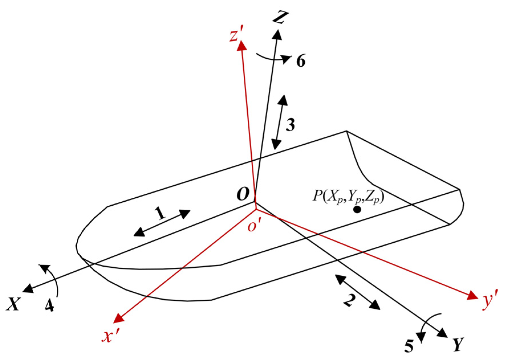
Figure 1. The geometry of a ship’s 6-DOF motion. P is a point target fixed on the ship.
Remotesensing 13 01821 g001
Figure 2. The geometry of a ship target. The o-xyz represents the fixed space coordinate system.
Remotesensing 13 01821 g002
Figure 3. The geometry of a point target with linear oscillation.
Remotesensing 13 01821 g003
Figure 4. The range distortions introduced by target linear oscillation. (a) Oscillating along the range direction; (b) oscillating along the azimuth direction. Red solid lines represent the true values of the range distortions obtained by numerical calculation. Blue dotted lines are the results obtained by proposed model, which are basically coincide with the red lines. Yellow dot-dash lines are the results obtained by the model in reference [7].
Remotesensing 13 01821 g004
Figure 5. The micro-Doppler introduced by target linear oscillation. (a) Oscillating along the range direction; (b) oscillating along the azimuth direction.
Remotesensing 13 01821 g005
Figure 6. The geometry of a ship with angular oscillation.
Remotesensing 13 01821 g006
Figure 7. The trajectories of point P in the fixed space coordinate system during 30 s. (a) Point oscillates with the destroyer; (b) point oscillates with the carrier.
Remotesensing 13 01821 g007
Figure 8. The range distortions of point P caused by ship angular oscillations. (a) Destroyer, roll motion; (b) destroyer, pitch motion; (c) destroyer, yaw motion; (d) destroyer, all the three angular oscillations; (e) carrier, roll motion; (f) destroyer, pitch motion; (g) destroyer, yaw motion; (h) carrier, all the three angular oscillations. Red solid lines represent the true values of the range distortions obtained by numerical calculation. Blue dotted lines are the results obtained by proposed model, which are basically coincide with the red lines. Yellow dot-dash lines are the results obtained by the model in reference [7].
Remotesensing 13 01821 g008
Figure 9. The micro-Doppler of point P introduced by ship oscillations. (a) Destroyer, roll motion; (b) destroyer, pitch motion; (c) destroyer, yaw motion; (d) destroyer, all the three angular oscillations; (e) carrier, roll motion; (f) destroyer, pitch motion; (g) destroyer, yaw motion; (h) carrier, all the three angular oscillations.
Remotesensing 13 01821 g009
Figure 10. The maximum variation of phase error components from 1st-order to 4th-order, the oscillation period and amplitude is set as 30 s and 1 m, respectively. (a) Target oscillates along the range direction; (b) target oscillates along the azimuth direction.
Remotesensing 13 01821 g010
Figure 11. Focusing results of point target with linear oscillations. (a) Target oscillates along the range direction, φl = 0; (b) target oscillates along the range direction, φl = π/2; (c) target oscillates along the azimuth direction, φl = 0; (d) target oscillates along the azimuth direction, φl = π/2. The red dot represents the true position of the target.
Remotesensing 13 01821 g011
Figure 12. The maximum variation of each order phase error components introduced by destroyer angular oscillation. (a) Roll motion; (b) pitch motion; (c) yaw motion; (d) all the three angular oscillations.
Remotesensing 13 01821 g012
Figure 13. Focusing results of the point target with angular oscillations of the destroyer on sea-state 5. (a) Roll motion, Ψ x = 0 ; (b) pitch motion, Ψ y = 0 ; (c) yaw motion, Ψ z = 0 ; (d) all the three angular oscillations, Ψ x = Ψ y = Ψ z = 0 ; (e) roll motion, Ψ x = π / 2 ; (f) pitch motion, Ψ y = π / 2 ; (g) yaw motion, Ψ z = π / 2 ; (h) all the three angular oscillations, Ψ x = Ψ y = Ψ z = π / 2 .
Remotesensing 13 01821 g013
Figure 14. The maximum variation of phase error components introduced by carrier angular oscillation. (a) Roll motion; (b) pitch motion; (c) yaw motion; (d) all the three-axis oscillations.
Remotesensing 13 01821 g014
Figure 15. Focusing results of the point target with angular oscillations of the carrier on sea-state 5. (a) Roll motion, Ψ x = 0 ; (b) pitch motion, Ψ y = 0 ; (c) yaw motion, Ψ z = 0 ; (d) all the three angular oscillations exist, Ψ x = Ψ y = Ψ z = 0 ; (e) roll motion, Ψ x = π / 2 ; (f) pitch motion, Ψ y = π / 2 ; (g) yaw motion, Ψ z = π / 2 ; (h) all the three angular oscillations exist, Ψ x = Ψ y = Ψ z = π / 2 .
Remotesensing 13 01821 g015
Figure 16. The effect of sinusoidal phase error. (a) Sinusoidal phase error; (b) linearly modulated sinusoidal phase error. The blue line represents the pulse compression result of the original LFM signal, the red line represents the pulse compression result of the signal added phase error.
Remotesensing 13 01821 g016
Figure 17. Focusing results of point target with linear oscillation. (a) Target oscillates along the range direction, Al = 1 m; (b) target oscillates along the range direction, Al = 0.05 m; (c) target oscillates along the azimuth direction, Al = 1 m; (d) target oscillates along the azimuth direction, Al = 0.05 m.
Remotesensing 13 01821 g017
Figure 18. Focusing results of the point target with angular oscillations of two ships on sea-state 5. (a) Destroyer, roll motion; (b) destroyer, pitch motion; (c) destroyer, yaw motion; (d) destroyer, all the three angular oscillations; (e) carrier, roll motion; (f) carrier, pitch motion; (g) carrier, yaw motion; (h) carrier, all the three angular oscillations.
Remotesensing 13 01821 g018
Figure 19. Experimental condition of this test: (a) experimental vessel (20 m × 3 m); (b) fixed position and appearance of the IMU; (c) experimental region (an anchorage near Yantai Port).
Remotesensing 13 01821 g019
Figure 20. Part of the measured ship motion data during 200 s. (ac) Attitude angles of the experimental ship in the unanchored state, anchored state, and navigating state; (df) velocity of the experimental ship in the unanchored state, anchored state, and navigating state.
Remotesensing 13 01821 g020
Figure 21. Ship point-array model with a size of 20 m × 3 m × 4 m.
Remotesensing 13 01821 g021
Figure 22. The ship attitude angles used for imaging. (a) In the unanchored state; (b) in the anchored state; (c) in the navigating state.
Remotesensing 13 01821 g022
Figure 23. The focusing results of the oscillatory ship in the different states. (ae) In the unanchored state; (fj) in the anchored state; (ko) in the navigating state. The motion types from left to right are roll, pitch, yaw, all the three angular oscillations, and stationary.
Remotesensing 13 01821 g023
Figure 24. The measured ship attitude angles with a duration of 20 s. (a) A drifting ship in the unanchored state; (b) a drifting ship in the anchored state; (c) a moving ship in the navigating state.
Remotesensing 13 01821 g024
Figure 25. The fitting results of the measured ship attitude angles by using 1~8 terms of Fourier series. (ac) Roll, pitch, heading angles in the unanchored state; (df) roll, pitch, heading angles in the navigating state. The abscissa of the graph is the number of the terms used for fitting, and the ordinate is the R-square (coefficient of determination), which indicates the fitting effect.
Remotesensing 13 01821 g025
Figure 26. The residual phase errors of Point A, B, and C after phase compensation. (ad) In the unanchored state; (eh) in the navigating state. The number of sinusoidal terms used for fitting attitude angles from left to right is 1, 2, 3, 4.
Remotesensing 13 01821 g026
Figure 27. The refocusing results of the oscillatory ship after phase compensation. (ad) In the unanchored state; (eh) in the navigating state. The number of terms used for fitting attitude angles from left to right is 1, 2, 3, 4.
Remotesensing 13 01821 g027
Table 1. Symbol list.
SymbolsThe Meaning of Symbol
O-XYZThe ship-fixed coordinate system
o′-x′y′z′The interim space coordinate system
o-xyzThe fixed space coordinate system
Δ X , Δ Y , Δ Z The coordinate changes caused by the ship’s surge, sway, and heave
A x , A y , A z The amplitude of the ship’s surge, sway, and heave
ω x , ω y , ω z The angular frequency of the ship’s surge, sway, and heave
φ x , φ y , φ z The initial phase of the ship’s surge, sway, and heave
A l , ω l , φ l The amplitude, angular frequency, and initial phase of a linearly oscillating target along an axis of the space
θ x , θ y , θ z The roll angle, pitch angle, and yaw angle of the ship
B x , B y , B z The amplitude of the ship’s roll, pitch, and yaw
Ω x , Ω y , Ω z The angular frequency of ship’s roll, pitch, and yaw
Ψ x , Ψ y , Ψ z The initial phase of the ship’s roll, pitch, and yaw
H The height of the radar platform (airplane)
v a The velocity of the radar platform
v s The velocity of the ship
α v Heading angle, the angle between ship’s sailing direction and x-axis
α 0 Radar observation angle, the angle between the RLOS 1 projection direction and the platform moving direction
α 1 The angle between the projection of linear oscillation axis and y-axis
β 0 Grazing angle, the angle between the RLOS direction and the sea level
β 1 The angle between the linear oscillation axis and the sea level
1 RLOS = radar line of sight.
Table 2. Description of 6-DOF oscillatory motion of the ship.
Serial NumberMotion NameDescription
1SurgeThe linear oscillation of a ship along its longitudinal axis.
2SwayThe linear oscillation of a ship along its transverse axis.
3HeaveThe linear oscillation of a ship along its vertical axis.
4RollThe angular oscillation of a ship around its longitudinal axis.
5PitchThe angular oscillation of a ship around its transverse axis.
6YawThe angular oscillation of a ship around its vertical axis.
Table 3. Computed worst-case ship motion parameters for two ship types in sea-state 5.
Ship TypeMotion TypeDouble Amplitude (deg)Average Period (sec)
DestroyerRoll38.412.2
Pitch3.46.7
Yaw3.814.2
CarrierRoll5.026.4
Pitch0.911.2
Yaw1.3333.0
Table 4. The system parameters of SAR simulation.
SymbolParameter Values
f Center Frequency5.4 GHz
f a Pulse Repetition Frequency (PRF)420 Hz
B r Signal Bandwidth300 MHz
H Platform Height6 km
β 0 Grazing Angle40°
θ r c Squint Angle
v a Platform Velocity140 m/s
L D Antenna Length1 m
T 0 CPI3.73 s
Table 5. Effects of different order phase errors on azimuth images.
Phase Error OrderEffects on SAR Azimuth Images
1Peak displacement
2Defocus of impulse response, decrease of peak amplitude
3Unbalanced sidelobes, peak displacement, and amplitude decrease
4Symmetrical increase of sidelobe, decrease of peak amplitude
Higher-orderPaired echoes, ghost images
Table 6. Summary of the sea states during data acquisition.
DataCenter PositionParameterValue
28-12-2019
08:14 (local time)
37°39.815N
121°29.812E
Wind speed4.8 m/s
Wind direction211.2°
Wave height0.7 m
28-12-2019
14:14 (local time)
37°40.395N
121°31.293E
Wind speed4.0 m/s
Wind direction209.0°
Wave height0.5 m
Table 7. Ship attitude angles comparison in different states.
Ship StateVariation Range (deg)Standard Deviation (deg)
RollPitchYawRollPitchYaw
Unanchored7.143.6614.591.230.494.84
Anchored6.302.635.711.220.451.64
Navigating6.532.7133.390.990.489.36
Publisher’s Note: MDPI stays neutral with regard to jurisdictional claims in published maps and institutional affiliations.