
From GPS Receiver to GNSS Reflectometry Payload Development for the Triton Satellite Mission


Abstract
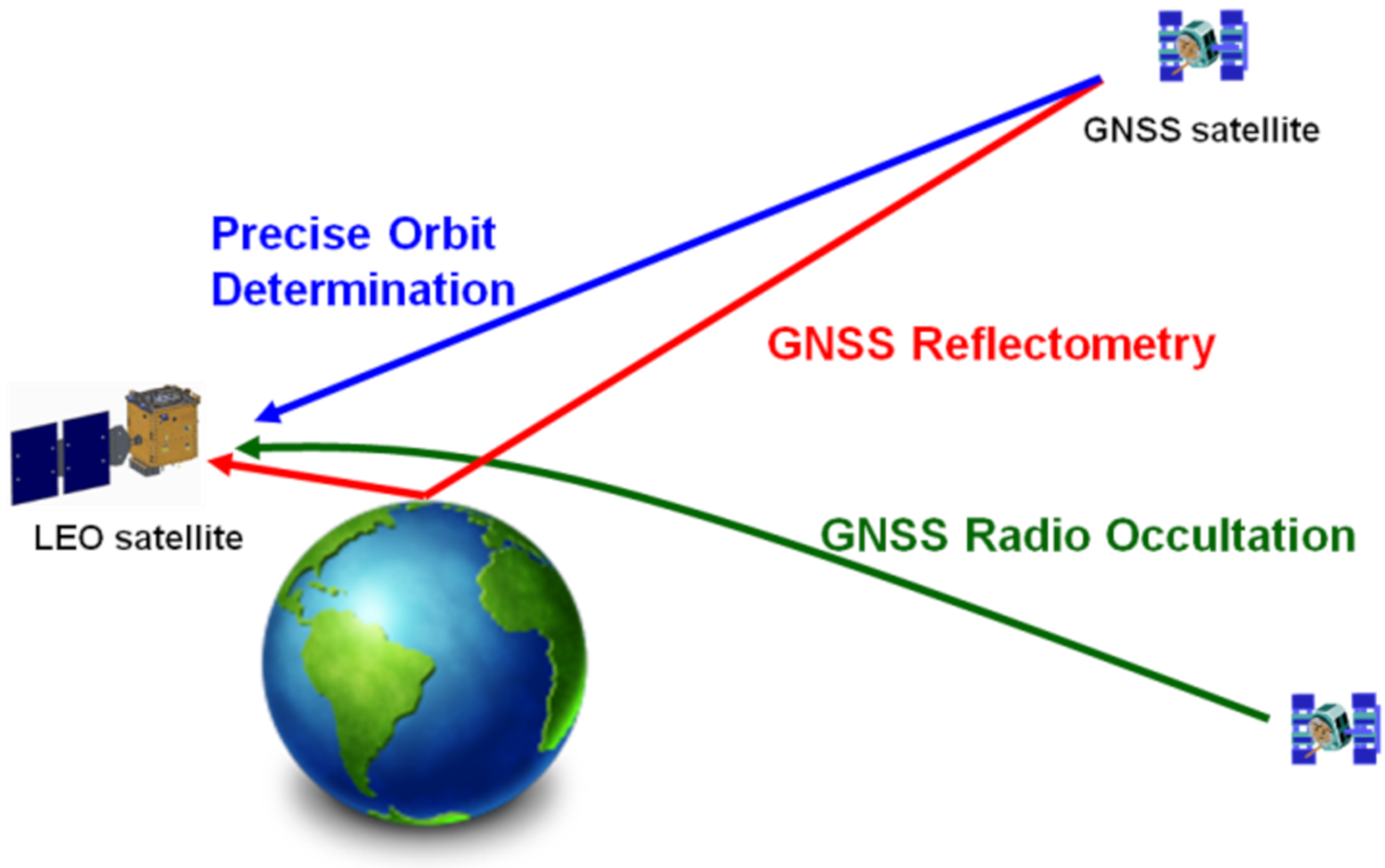
1. Introduction
Triton Satellite Mission
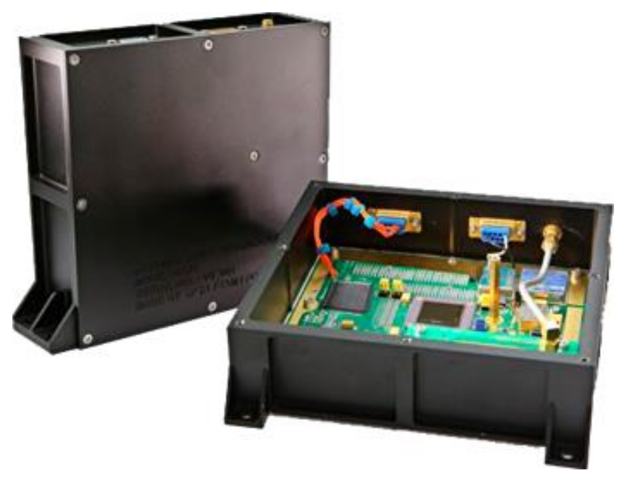
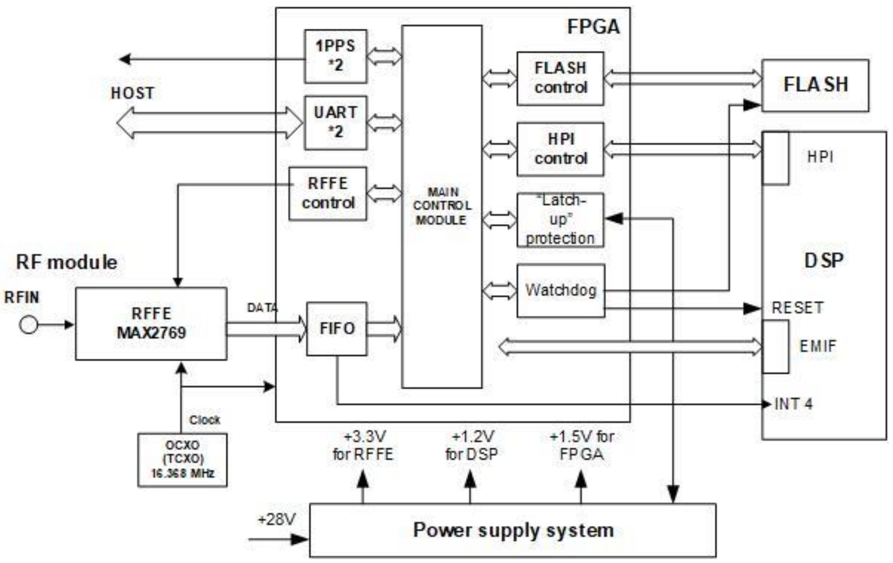
2. GPS Receiver (GPSR) Design/Development
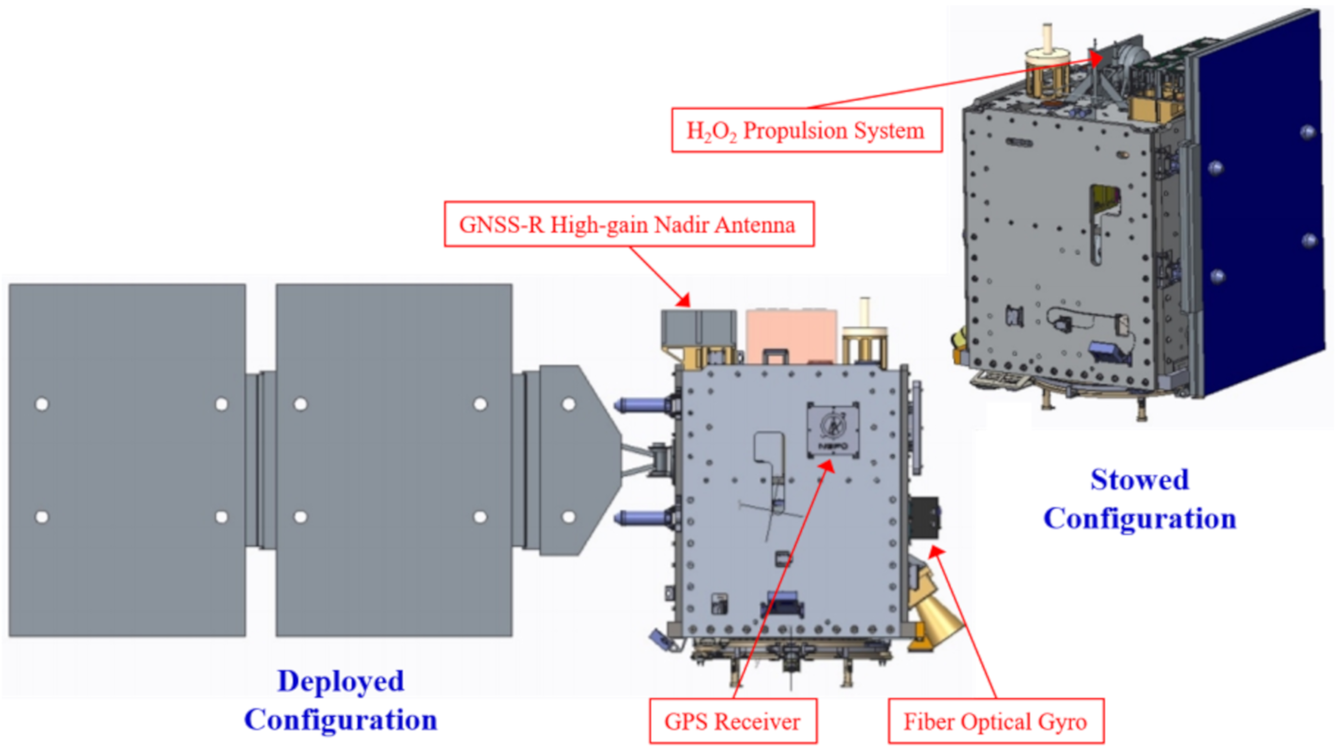
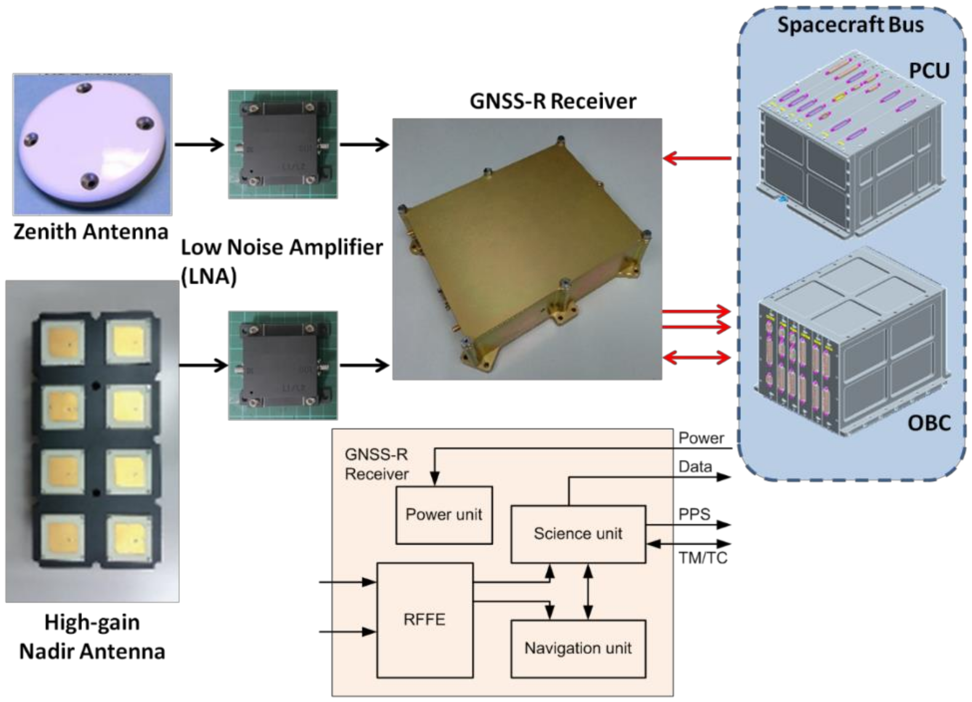
3. GNSS Reflectometry (GNSS-R) Mission Payload
3.1. GNSS-R Payload Design
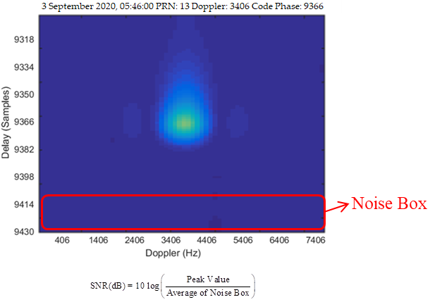
- The GNSS-R payload shall be able to process GPS L1 reflection signals and then generate the associated delay–Doppler map (DDM), either autonomously or by schedule.
- The generated DDM resolution shall be at least 128 (in code phase) * 64 (in frequency bin) and each entry of the DDM shall be better than 16 bits.
- The GNSS-R payload shall be capable of processing at least four DDMs simultaneously.
- The DDM update rate shall be at least 1 s.
- The GNSS-R payload should potentially be extended to process reflected Quasi-Zenith Satellite System (QZSS) [19] and Galileo L1 signals and generate DDMs of the aforementioned space, magnitude, and time resolution in real time.
- The GNSS-R payload shall be able to record direct line-of-sight and reflected GPS L1/L2 band signals in raw data format at the intermediate frequency (IF) for ground post-processing purposes.
- The GNSS-R payload shall include at least 512 M bytes of RAM to store the raw data.
- The GNSS-R payload shall be designed with a process-and-record mode for ground debugging purpose.
- The GNSS-R payload shall facilitate meta-data to support calibration and retrieval.
- A higher DDM resolution (CYGNSS: one-fourth chip / 500 Hz, Triton: one-sixteenth chip / 125 Hz)
- A real-time QZSS reflected signal processing capability
- The capability to generate eight DDM generations per second
- On-orbit software/firmware modification capability
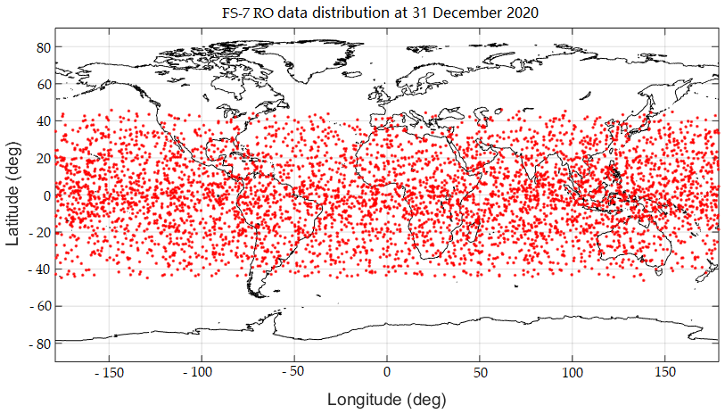
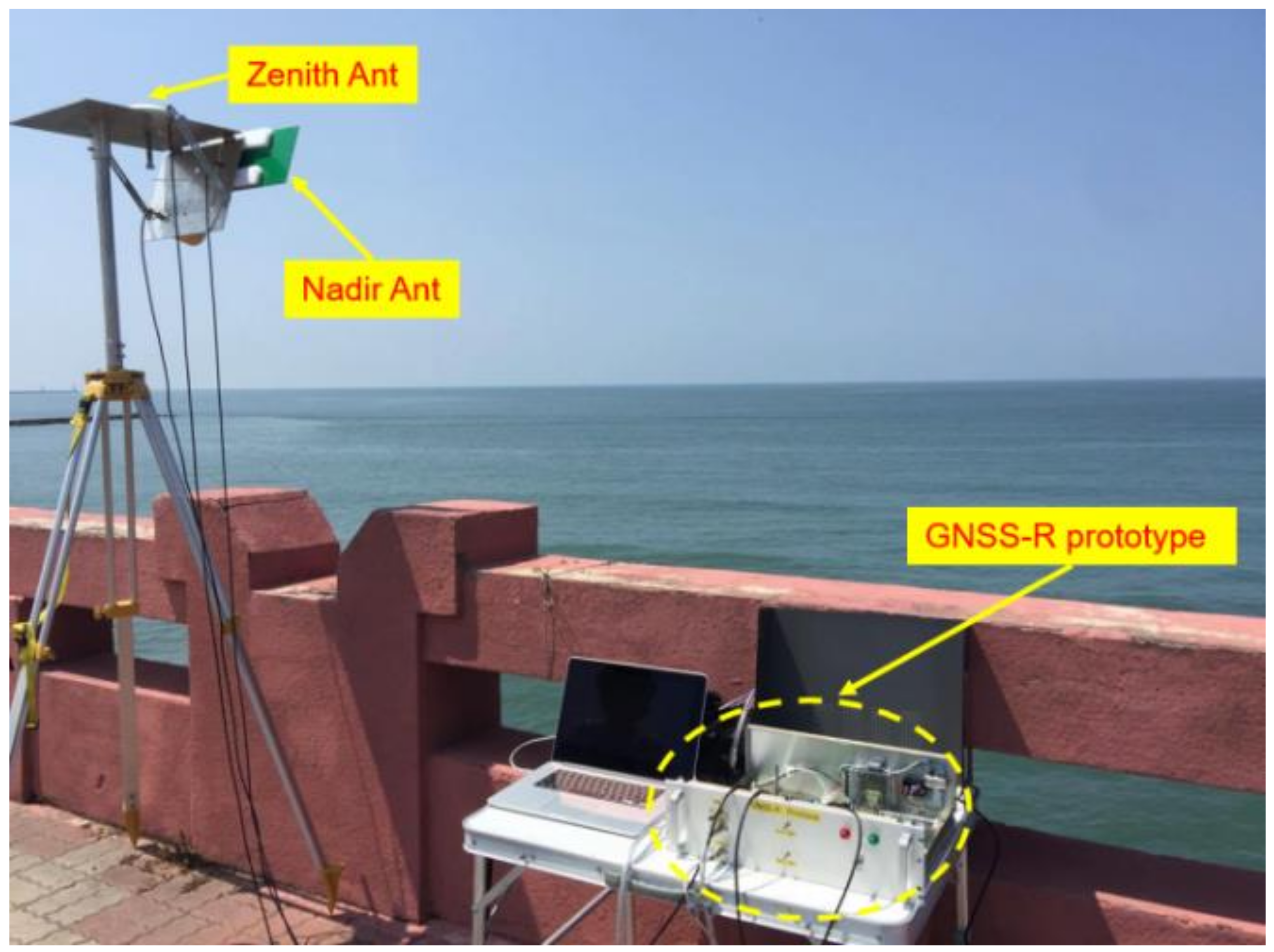
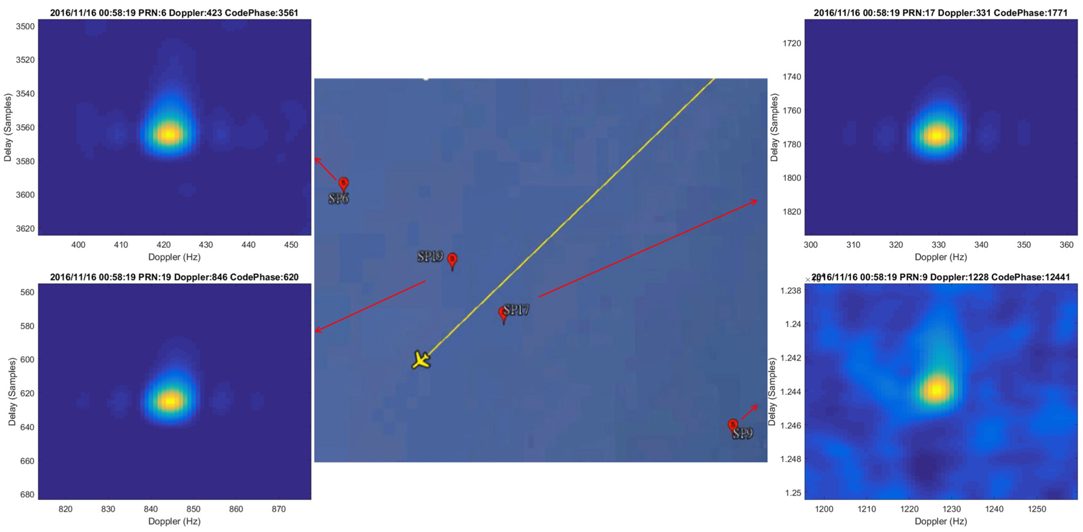
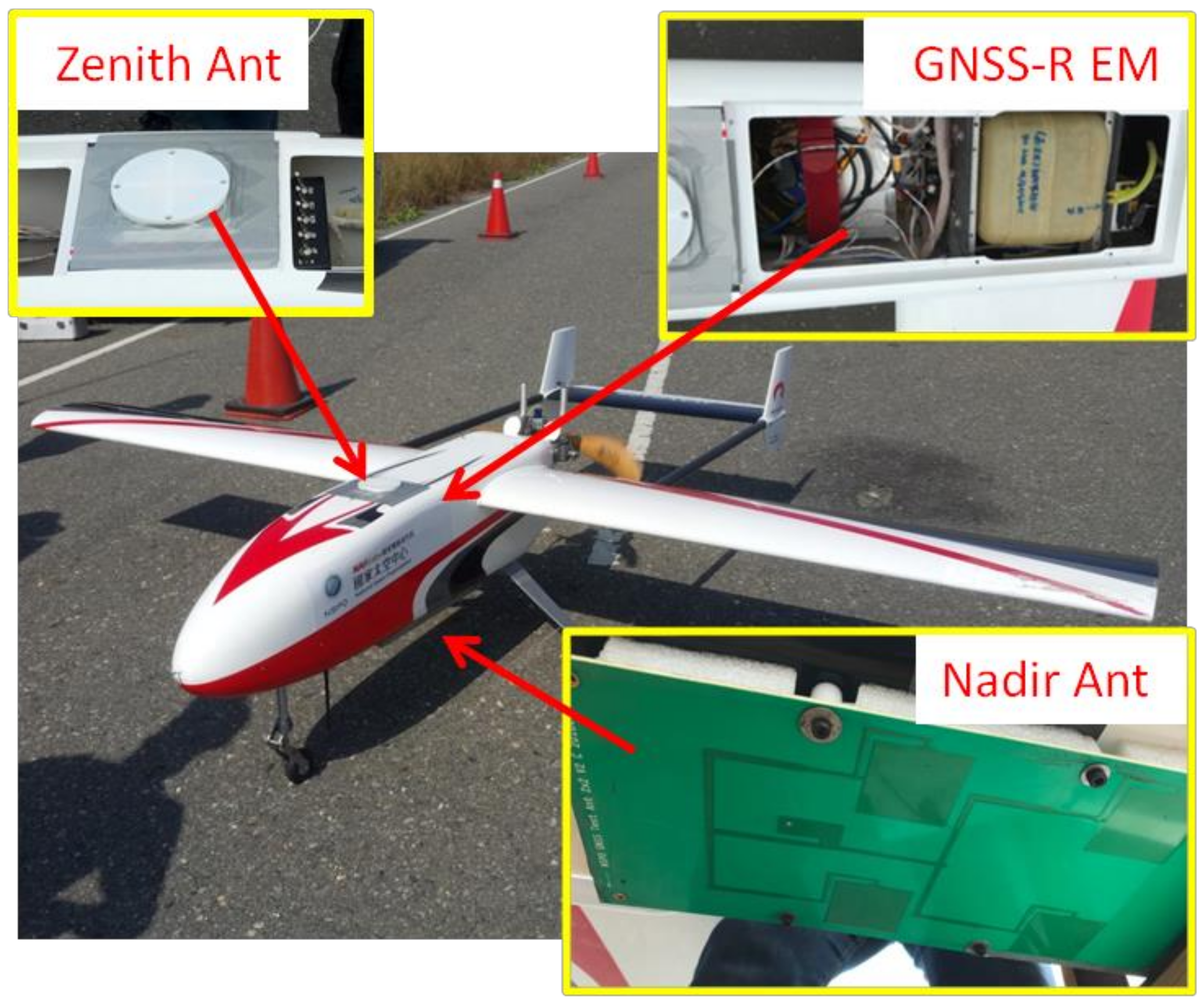
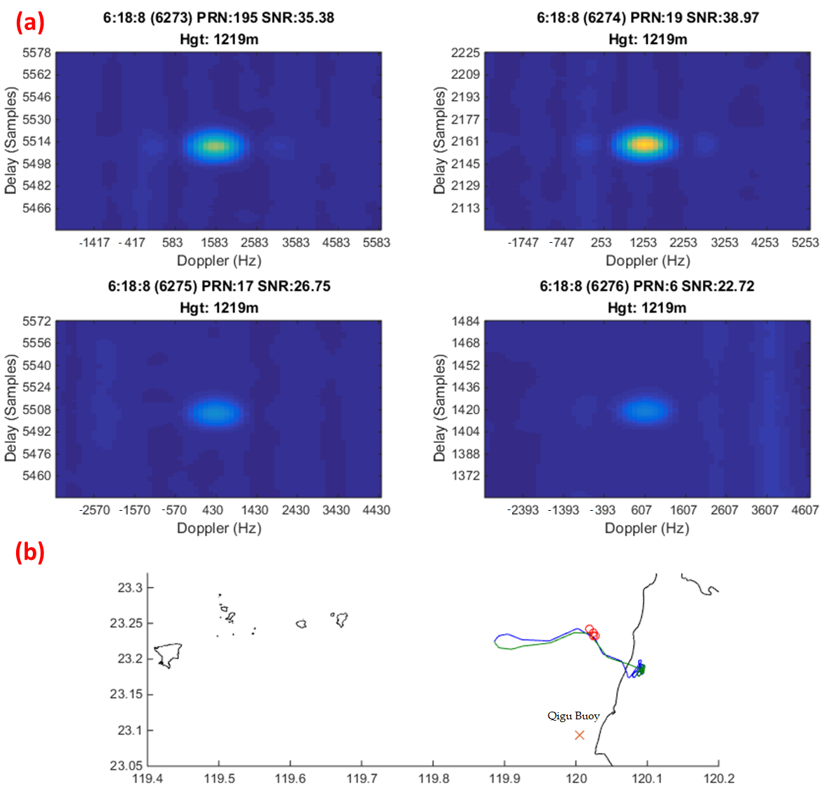
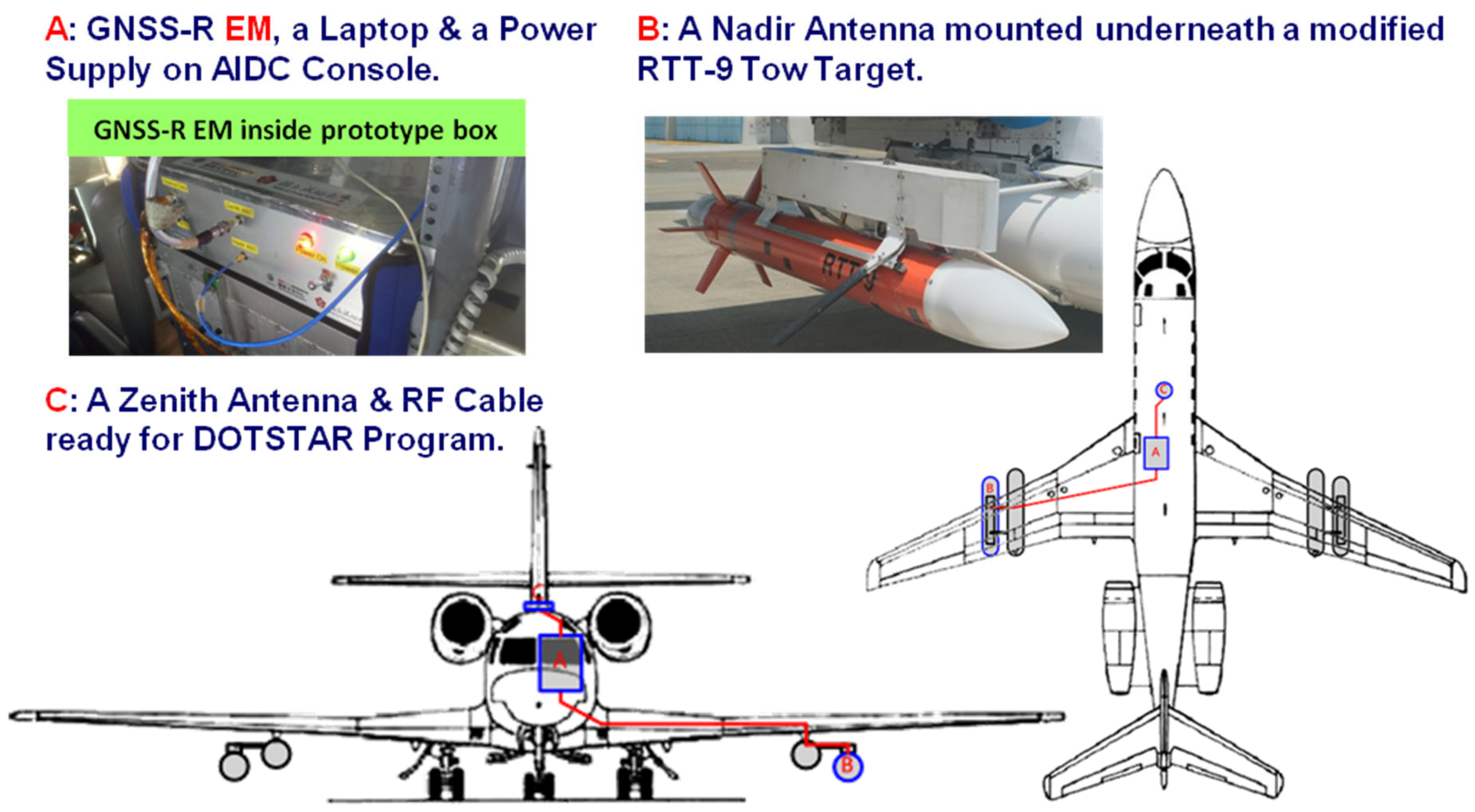
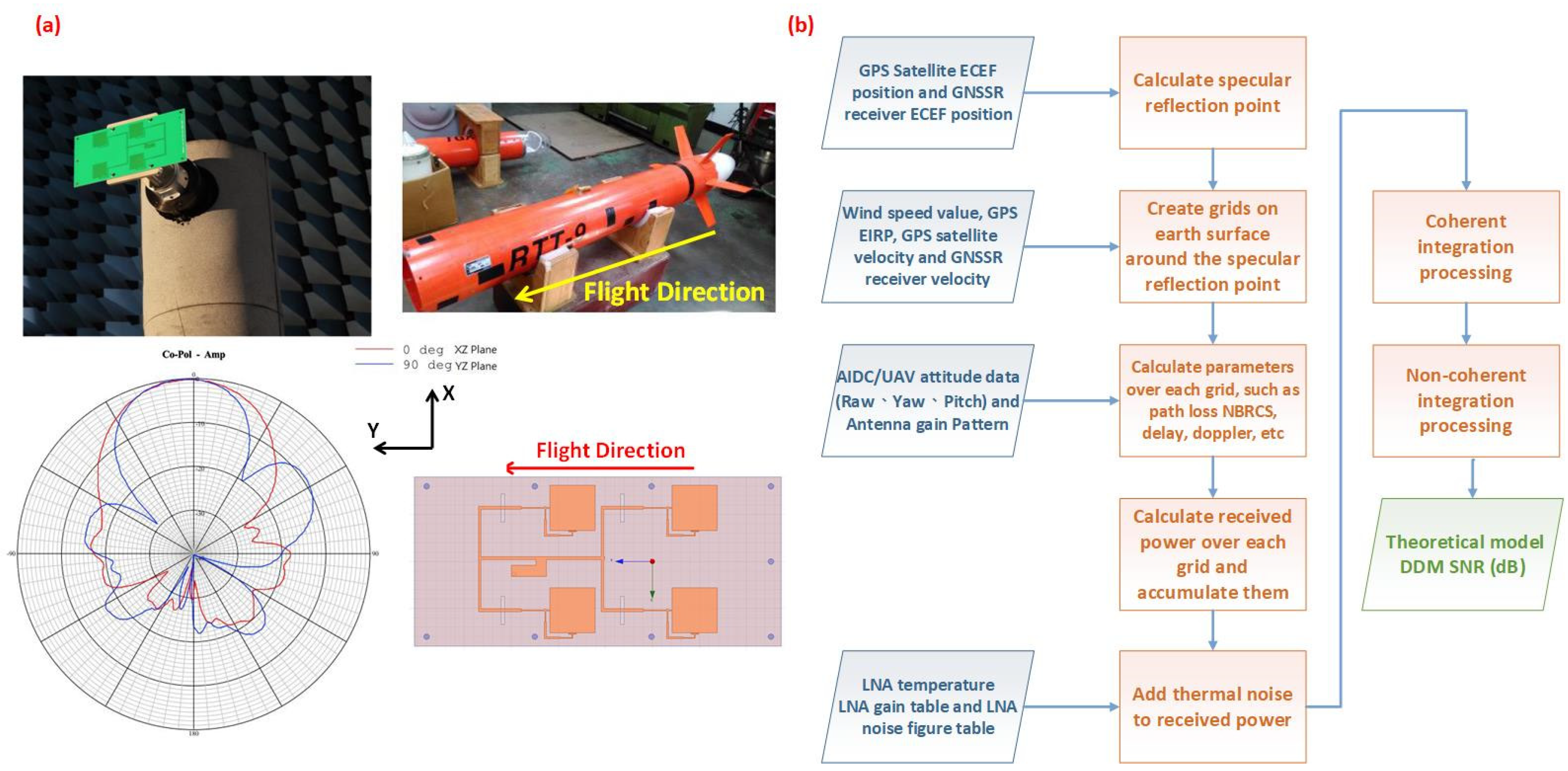
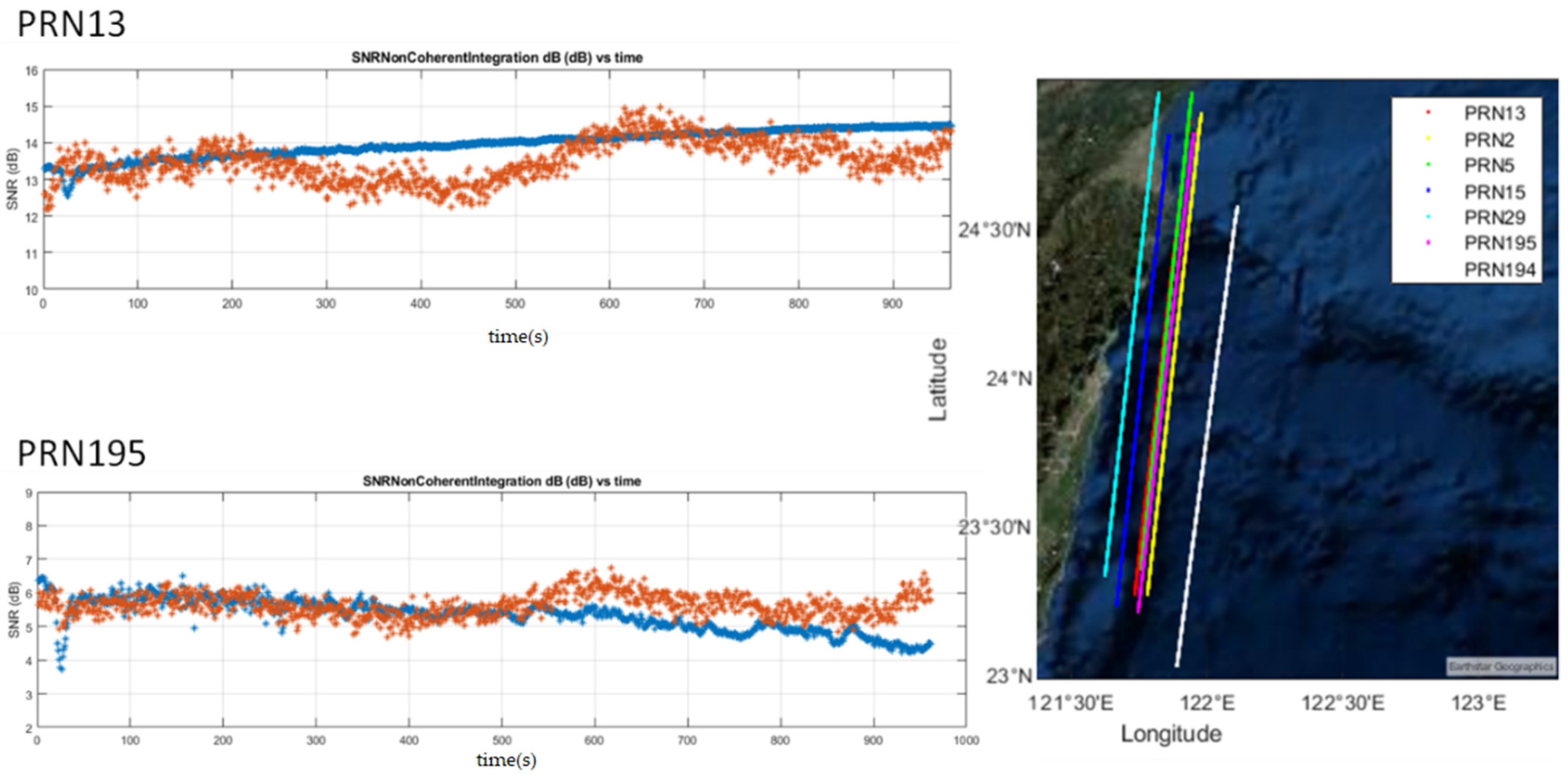
3.2. GNSS-R Payload Validation
4. Conclusions
Author Contributions
Funding
Acknowledgments
Conflicts of Interest
References
- Juang, J.C.; Lin, C.F.; Hu, C.M.; Chang, C.C.; Tsai, Y.F.; Lin, C.T. Implementation and Test of a Space-borne GPS Receiver Payload of University Microsatellite. J. Aeronaut. Astronaut. Aviat. 2012, 44, 141–148. [Google Scholar]
- News of NSPO, Taiwan. Available online: http://www.nspo.narl.org.tw/en2016/info/news.shtml?id=000527&hid=ruEdk2nA2B (accessed on 1 March 2021).
- FORMOSAT-7 Program, NSPO, Taiwan. Available online: https://www.nspo.narl.org.tw/inprogress.php?c=20022301&ln=en (accessed on 1 March 2021).
- TRITON Program, NSPO, Taiwan. Available online: https://www.nspo.narl.org.tw/inprogress.php?c=20030305&ln=en (accessed on 1 March 2021).
- Gleason, S.; Hodgart, S.; Sun, Y.; Gommenginger, C.; Mackin, S.; Adjrad, M.; Unwin, M. Detection and processing of bistatically reflected GPS signals from low earth orbit for the purpose of ocean remote sensing. IEEE Trans. Geosci. Remote Sens. 2005, 43, 1229–1241. [Google Scholar] [CrossRef]
- Martin-Neira, M.; Caparrini, M.; Font-Rossello, J.; Lannelongue, S.; Vallmitjana, C.S. The PARIS concept: An experimental demonstration of sea surface altimetry using GPS reflected signals. IEEE Trans. Geosci. Remote Sens. 2001, 39, 142–150. [Google Scholar] [CrossRef]
- Yan, Q.; Huang, W. Spaceborne GNSS-R sea ice detection using delay-Doppler maps: First results from the UK TechDemoSat-1 mission. IEEE J. Sel. Top. Appl. Earth Obs. Remote Sens. 2016, 9, 4795–4801. [Google Scholar] [CrossRef]
- Small, E.E.; Larson, K.M.; Braun, J.J. Sensing vegetation growth with reflected GPS signals. Geophys. Res. Lett. 2010, 37. [Google Scholar] [CrossRef]
- Rodriguez-Alvarez, N.; Bosch-Lluis, X.; Camps, A.; Vall-Llossera, M.; Valencia, E.; Marchan-Hernandez, J.F.; Ramos-Perez, I. Soil moisture retrieval using GNSS-R techniques: Experimental results over a bare soil field. IEEE Trans. Geosci. Remote Sens. 2009, 47, 3616–3624. [Google Scholar] [CrossRef]
- Tsai, Y.F.; Lin, C.T.; Juang, J.C. Taiwan’s GNSS Reflectometry Mission—The FORMOSAT-7 Reflectometry (FS-7R) Mission. J. Aeronaut. Astronaut. Aviat. 2018, 50, 391–404. [Google Scholar]
- Datasheet of MAX2769 Universal GPS Receiver. Available online: https://www.maximintegrated.com/en/products/comms/wireless-rf/MAX2769.html (accessed on 1 March 2021).
- Datasheet of Space GPS Receiver SGR-07. Available online: https://sstl-qa.azurewebsites.net/getattachment/Media-Hub/Featured/Navigation/SGR-07-Datasheet-2018-V2-Read-Only.pdf?lang=en-GB (accessed on 1 March 2021).
- Chang, H.Y.; Chang, H.C.; Lin, C.T. Performance Demonstration of NSPO Space-borne GPS Receiver. In Proceedings of the 26th International Technical Meeting of the Satellite Division of The Institute of Navigation (ION GNSS+ 2013), Manassas, VA, USA, 21–25 September 2013. [Google Scholar]
- Chang, H.Y.; Chiang, W.L.; Wu, K.L. A Space-Borne GNSS Receiver for Evaluation of the LEO Navigation Based on Real-Time Platform. In Proceedings of the CEAS Euro GNC Conference, Warsaw, Poland, 25–27 April 2017. [Google Scholar]
- Cheng, C.C.; Lin, C.T.; Chen, T.L. TID Testing and SEE Mitigation Approach of a Long Mission Life GPS Receiver Using COTS Parts. In Proceedings of the 6th ESA Workshop on Satellite Navigation Technologies, Noordwijk, The Netherlands, 5–7 December 2012. [Google Scholar]
- Zavorotny, V.U.; Gleason, S.; Cardellach, E.; Camps, A. Tutorial on remote sensing using GNSS bistatic radar of opportunity. IEEE Geosci. Remote Sens. Mag. 2014, 2, 8–45. [Google Scholar] [CrossRef]
- Unwin, M.; de Vos Van Steenwijk, R.; Da Silva Curiel, A.; Cutter, M.; Abbott, B.; Gommenginger, C.; Mitchell, C.; Gao, S. Remote sensing using GPS signals—The SGR-ReSI instrument. In Proceedings of the 25th Annu. AIAA/USU Conf. Small Satellites, Logan, UT, USA, 8–11 August 2011. [Google Scholar]
- Juang, J.C.; Ma, S.H.; Lin, C.T. Study of GNSS-R Techniques for FORMOSAT Mission. IEEE J. Sel. Top. Appl. Earth Obs. Remote Sens. 2016, 9, 4582–4592. [Google Scholar] [CrossRef]
- Quasi-Zenith Satellite System (QZSS). Available online: https://qzss.go.jp/en/overview/services/index.html (accessed on 1 March 2021).
- CYGNSS Mission. Available online: https://clasp-research.engin.umich.edu/missions/cygnss/ (accessed on 1 March 2021).
- Juang, J.C.; Lin, C.T. Recent Development in GNSS-Reflected Signal Processing and Receiver Research in Taiwan. In Proceedings of the COSMIC/IROWG, Estes Park, CO, USA, 21–27 September 2017. [Google Scholar]
- Juang, J.C.; Ma, S.H.; Lin, C.T. Data Analysis of Galileo Reflected Signals in an Airborne Experiment. In Proceedings of the GNSS+R, 2017 Workshop, University of Michigan Union, Ann Arbor, MI, USA, 23–25 May 2017. [Google Scholar]
- DOTSTAR Project. Available online: http://typhoon.as.ntu.edu.tw/DOTSTAR/en/ (accessed on 1 March 2021).
- Juang, J.C.; Tsai, Y.F.; Lin, C.T. FORMOSAT-7R Mission for GNSS Reflectometry. In Proceedings of the 2019 IEEE International Geoscience and Remote Sensing Symposium, IGARSS 2019, Yokohama, Japan, 28 July–2 August 2019. [Google Scholar]
- Juang, J.C.; Lin, C.T.; Tsai, Y.F. Comparison and Synergy of BPSK and BOC Modulations in GNSS Reflectometry. IEEE J. Sel. Top. Appl. Earth Obs. Remote Sens. 2020. [Google Scholar] [CrossRef]
- Drifter Technology Co. Ltd. Available online: http://driftertek.com/ (accessed on 1 March 2021).
- O’Brien, A. End-to-end Simulator Technical Memo. CYGNSS Project Doc 148-0123. Available online: https://clasp-research.engin.umich.edu/missions/cygnss/reference/148-0123_CYGNSS_E2ES_EM.pdf (accessed on 1 March 2021).
- Yang, D.S.; Juang, J.C.; Lin, C.T.; Tsai, Y.F. Verification of GNSS-R Signals for the Triton Mission Payload. In Proceedings of the ICGPSRO 2020, Hsinchu, Taiwan, 21–23 October 2020. [Google Scholar]
- Tsai, Y.F.; Hsieh, M.Y.; Chang, H.Y.; Lin, C.T. Development and Test of a Space Capable Miniaturized GPS/GNSS Receiver for Space Applications. In Proceedings of the ION ITM/PTTI 2018, Reston, Virginia, 29 January–1 February 2018. [Google Scholar]


| Input power | 28 V/3.5 W |
| Electrical interface | RS422/UART@115200 bps & 1 PPS output |
| Tracking channels | GPS L1 C/A×12 |
| Tracking threshold | 33 dB-Hz |
| Max Doppler shift | ±65 KHz. |
| Position accuracy | Better than 8 m (1 sigma) |
| Velocity accuracy | Better than 0.1 m/s (1 sigma) |
| Time accuracy | Better than 1 micro-second |
| Cold start time | Within 90 s |
| Trajectory dynamic | Up to 12 g |
| Mass | 1.8 kg |
| Dimension | 160 × 120 × 40 mm |
| Mission life | 5 years |
| Total doze | 35 Krad |
Publisher’s Note: MDPI stays neutral with regard to jurisdictional claims in published maps and institutional affiliations. |
© 2021 by the authors. Licensee MDPI, Basel, Switzerland. This article is an open access article distributed under the terms and conditions of the Creative Commons Attribution (CC BY) license (http://creativecommons.org/licenses/by/4.0/).
Share and Cite
Tsai, Y.-F.; Yeh, W.-H.; Juang, J.-C.; Yang, D.-S.; Lin, C.-T. From GPS Receiver to GNSS Reflectometry Payload Development for the Triton Satellite Mission. Remote Sens. 2021, 13, 999. https://doi.org/10.3390/rs13050999
Tsai Y-F, Yeh W-H, Juang J-C, Yang D-S, Lin C-T. From GPS Receiver to GNSS Reflectometry Payload Development for the Triton Satellite Mission. Remote Sensing. 2021; 13(5):999. https://doi.org/10.3390/rs13050999
Chicago/Turabian StyleTsai, Yung-Fu, Wen-Hao Yeh, Jyh-Ching Juang, Dian-Syuan Yang, and Chen-Tsung Lin. 2021. "From GPS Receiver to GNSS Reflectometry Payload Development for the Triton Satellite Mission" Remote Sensing 13, no. 5: 999. https://doi.org/10.3390/rs13050999
APA StyleTsai, Y.-F., Yeh, W.-H., Juang, J.-C., Yang, D.-S., & Lin, C.-T. (2021). From GPS Receiver to GNSS Reflectometry Payload Development for the Triton Satellite Mission. Remote Sensing, 13(5), 999. https://doi.org/10.3390/rs13050999