Article

Single-Satellite Integrated Navigation Algorithm Based on Broadband LEO Constellation Communication Links

1
School of Electronic and Information Engineering, Xi’an Jiao Tong University (XJTU), Xi’an 710049, China
2
State Key Laboratory of Astronautic Dynamics, Xi’an Satellite Control Center, General Armament Department, Xi’an 710049, China
*
Author to whom correspondence should be addressed.
Remote Sens. 2021, 13(4), 703; https://doi.org/10.3390/rs13040703
Submission received: 30 December 2020 / Revised: 3 February 2021 / Accepted: 11 February 2021 / Published: 15 February 2021
(This article belongs to the Section Satellite Missions for Earth and Planetary Exploration)

Abstract

:
With the rapid development of satellite technology and the need to satisfy the increasing demand for location-based services, in challenging environments such as indoors, forests, and canyons, there is an urgent need to improve the position accuracy in these environments. However, traditional algorithms obtain the position solution through time redundancy in exchange for spatial redundancy, and they require continuous observations that cannot satisfy the real-time location services. In addition, they must also consider the clock bias between the satellite and receiver. Therefore, in this paper, we provide a single-satellite integrated navigation algorithm based on the elimination of clock bias for broadband low earth orbit (LEO) satellite communication links. First, we derive the principle of LEO satellite communication link clock bias elimination; then, we give the principle and process of the algorithm. Next, we model and analyze the error of the system. Subsequently, based on the unscented Kalman filter (UKF), we model the state vector and observation vector of our algorithm and give the state and observation equations. Finally, for different scenarios, we conduct qualitative and quantitative analysis through simulations, and the results show that, whether in an altimeter scenario or non-altimeter scenario, the performance indicators of our algorithm are significantly better than the inertial navigation system (INS), which can effectively overcome the divergence problem of INS; compared with the medium earth orbit (MEO) constellation, the navigation trajectory under the LEO constellation is closer to the real trajectory of the aircraft; and compared with the traditional algorithm, the accuracy of each item is improved by more than 95%. These results show that our algorithm not only significantly improves the position error, but also effectively suppresses the divergence of INS. The algorithm is more robust and can satisfy the requirements of cm-level real-time location services in challenging environments.

1. Introduction

Although traditional global navigation satellite systems (GNSSs), as sophisticated and complex systems, are widely used in navigation, positioning, and timing, GNSSs still cannot overcome their own bottlenecks, such as their weak signal power (only 20 W power interference can cause denial of a cell’s GNSS signal [1]), coupled with multiple paths, especially in challenging environments, such as lush forests, canyons, cities with tall buildings, indoor locations, and polar regions. GNSS signals are easily blocked, and the number of visible satellites decreases as the visible elevation angle increases, leading to unusable multisatellite positioning. There are also deficiencies in the accuracy, reliability, availability, and anti-interference.
In recent years, a program to provide global internet access based on broadband low earth orbit (LEO) constellations has been reproposed. The purpose of this program is to provide truly global and robust broadband coverage and access, to expand the coverage of geosynchronous (GEO) satellites to polar regions, and to improve the user positioning accuracy [2]. Compared with traditional GNSSs, LEO constellations offer the advantages of a large number of satellites, high accuracy, and high availability and the LEO system can be used for communication, cm-level navigation enhancement, and positioning services. In addition, LEO satellites are closer to the earth, which means that less path loss and the stronger signal power undoubtedly enhance the anti-interference ability of the system, and they are considered to be an important direction for future development. Radio communication and navigation have many similar technical foundations, but they have different needs in terms of information transmission and signal measurement and have evolved along their own routes. With the rise of concepts such as the internet and autonomous driving, positioning and communication functions have become inseparable, and the necessity of communication and navigation integration has become a consensus. Therefore, the concept of integration of the technology of positioning, navigation, timing, remote sensing, and communication (PNTRC) has been proposed in recent years [3] PNTRC can be used as a space-based internet access station to solve global internet access problems, but also as a navigation and communication information source to achieve the rapid convergence of precise positioning, communication, and navigation realized by only one link. Therefore, the study of LEO constellation single-satellite positioning technology solutions based on PNTRC has the outstanding advantage of a high availability, thereby providing an opportunity to solve the problem of location services in the challenging environments mentioned above.
To apply the LEO constellation to the field of navigation and realize the PNTRC, many scholars have made bold attempts and provided many creative solutions. Reference [4] studied the feasibility and performance of the LEO constellation as a potential navigation enhancement platform and evaluated and analyzed the comprehensive performance, coverage rate, and signal strength of the LEO constellation. The results show that the LEO system has a better performance than GNSSs and can be used as a navigation enhancement platform in challenging environments. Reference [5] Based on PNTRC, the LEO communication satellite signal and the E-911 ground cellular signal have been integrated to provide positioning services. Reference [6] The new ideas and functions of PNTRC have been integrated into the signal system, and the basic technology of PNTRC has been researched at the signal-design level. To realize the benefits of PNTRC to enhance the GNSS system and improve the usability of LEO constellations, reference [7] proposed a global navigation enhancement system based on the LEO constellation. To improve the navigation availability and attain a better anti-jamming ability, reference [8] (from the perspective of a signal design system) proposed a frequency-hopping binary offset carrier (BOC) modulation scheme with a strong anti-interference ability, in order to improve the anti-jamming capability of LEO constellation navigation at the signal-design level.
For exploration of the application of a single satellite in navigation and positioning, references [9,10,11] located the radiation source by measuring the phase difference or frequency of the incoming wave. Additionally, references [12,13] proposed a positioning method based on a single-satellite Doppler integral, which has a high positioning accuracy for static targets, but the positioning accuracy decreases rapidly for dynamic targets. To overcome this problem, reference [12,13,14] proposed a scheme based on integrated navigation. Moreover, reference [15] proposed a single-satellite positioning method based on the inertial navigation system (INS) and Doppler pseudorange difference. To solve the problem of parameter estimation and target location being divided into two independent stages in traditional single-satellite positioning, a single-satellite passive location method using spatial sparsity is proposed in [16].
To cope with the demand for location services under challenging environmental conditions, different scholars have provided different solutions in different positioning situations. Reference [17] developed an INS that can be used by a navigation vehicle to assist INS through Doppler measurements and tightly coupled LEO satellite signals when GNSS signals are not available. Furthermore, reference [18] pointed out that under the condition of global coverage, users may have 1–3 visible satellites in different times and places and proposed that under different conditions, only Doppler observations should be used for positioning solutions. Reference [19] proposed a Doppler positioning algorithm based on a LEO satellite system in a complex environment when the GPS signal is accidentally blocked. To improve the dynamic positioning accuracy of single-satellite positioning in emergencies, reference [20] proposed an INS-aided single-satellite positioning algorithm in the case of GNSS system rejection. This INS-aided single-satellite positioning algorithm can provide certain space-based positioning services for dynamic targets.
The new single-satellite integrated navigation and positioning algorithm based on broadband LEO constellation communication links offers a low-cost approach, a strong engineering practicability, and an anti-jamming scheme. The accuracy of navigation and positioning is better than the accuracy of navigation and positioning of the traditional algorithm of single-satellite and MEO constellation algorithms, and effectively overcomes the problem of INS divergence. The new single-satellite integrated navigation and positioning algorithm can provide a cm-level navigation scheme for relevant personnel engaged in outdoor tourism, exploration, or scientific research in challenging environments, such as lush forests, canyons, high latitude areas, and polar regions, without relying on GNSS.
In Section 2, based on introducing the traditional single-satellite positioning algorithm, we give the principle of our algorithm and compare it with the traditional algorithm. Next, in Section 3, we model and analyze the errors involved in the system. In Section 4, based on the unscented Kalman filter (UKF), we model the state and observation vectors of the algorithm and give the corresponding state and observation equations. Finally, in Section 5, we simulate the algorithm and perform qualitative and quantitative analysis for different scenarios, comparing our algorithm with the traditional single-satellite navigation algorithm, and present our conclusion in the last section.

2. Algorithm Description

2.1. Traditional Single-Satellite Positioning Algorithm

2.1.1. Basic Principle of Positioning in a Static Environment

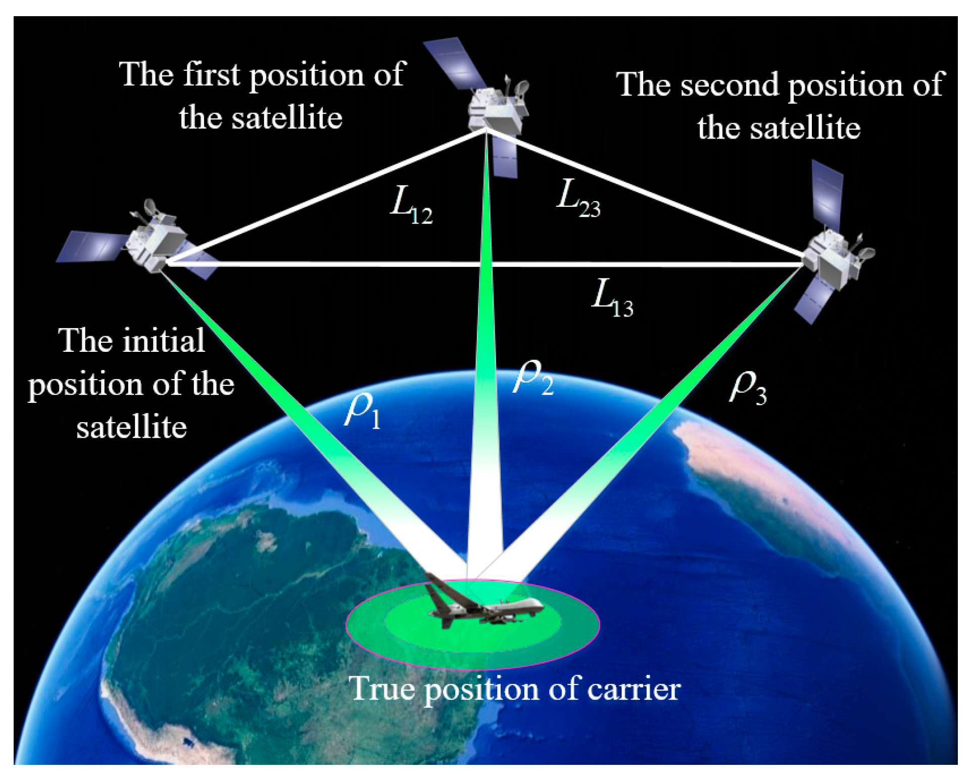
We know that the GNSS positioning system requires at least four visible satellites to complete the positioning. However, the single-satellite positioning system cannot obtain multiple sets of pseudorange information at the same time since it has only one satellite. Therefore, this algorithm obtains the positioning solution by exchanging time redundancy for space redundancy. The principle of the single-satellite positioning system is shown in Figure 1.
As can be seen in Figure 1, the integral Doppler measurement value d 12 = ρ 2 ρ 1 is obtained at the terminal of baseline L 12 , and the terminal of baseline L 13 obtains the measured value d 13 = ρ 3 ρ 1 plus the elevation value of the positioning target. Then, two positioning hyperboloids and a spherical surface are constructed. The coordinate value where the three curved surfaces intersect is the actual positioning result.

2.1.2. INS-Assisted Single-Satellite Positioning System

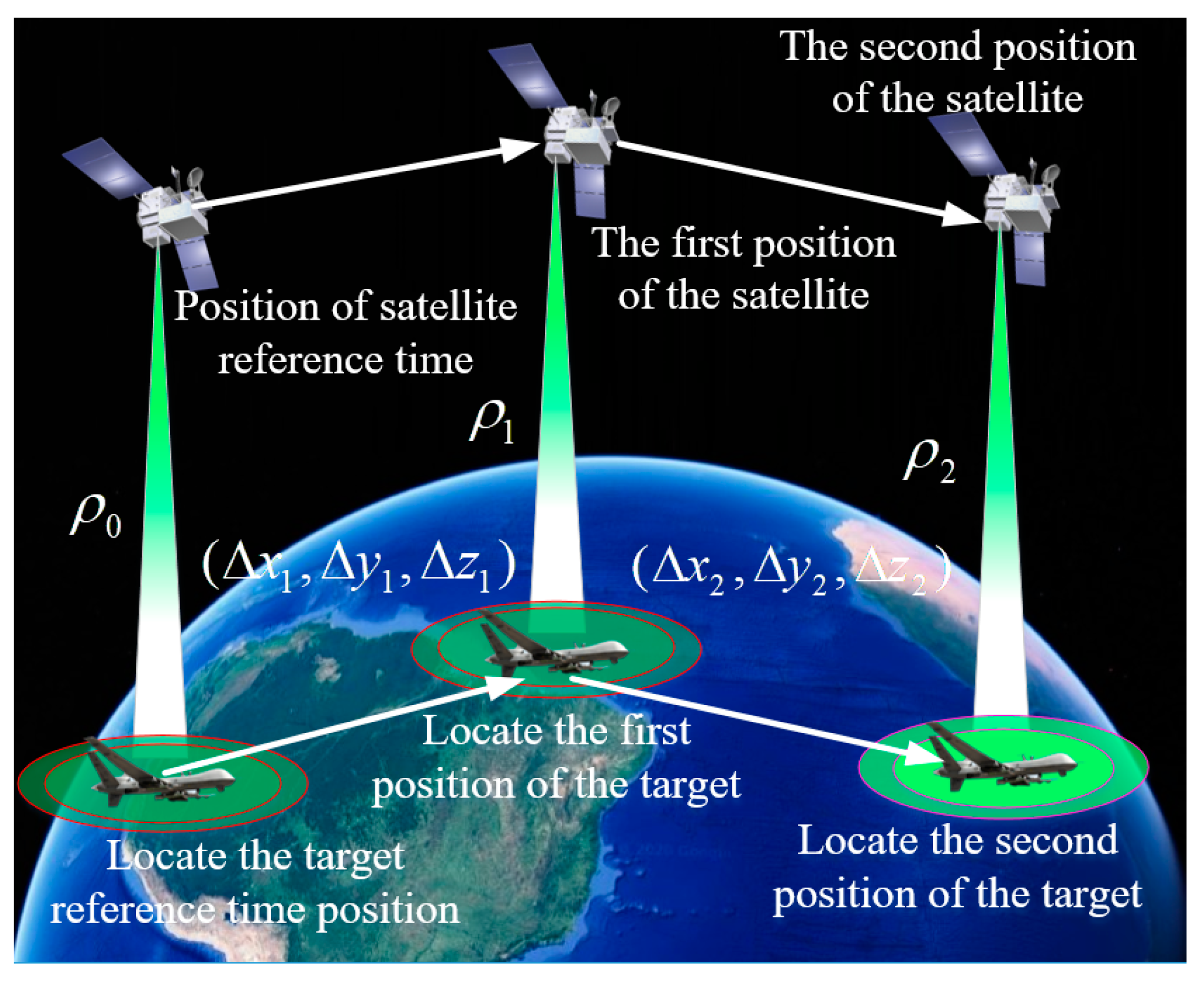
Compared with static positioning, since the aircraft is in a continuous motion state, the motion of the aircraft must be compensated for. The principle of the single-satellite positioning method based on inertial components is shown in Figure 2.
As displayed in Figure 2, taking any time as the initial reference time (the subscript is 0), three satellite moments are considered together as a group for calculation, and all the calculations are converted into the earth-centered earth-fixed (ECEF) coordinate system. ρ 0 , ρ 1 , and ρ 2 represent the pseudorange values between the satellite and the aircraft at the initial moment, first moment, and second moment of each group, respectively. Similarly, Δ x 0 , Δ y 0 , Δ z 0 and Δ x 1 , Δ y 1 , Δ z 1 represent the displacement changes on the x -axis, y -axis, and z -axis of the spacecraft between the initial moment and the first moment, as well as between the first and second moments of the satellite, respectively, which is also the recorded value of INS. Satellite positioning should obtain pseudorange values. For single-satellite positioning based on Doppler integration, three satellite pseudorange values are required for each group calculation, and the pseudorange calculation formula is as follows:
ρ i = ( X i x i ) 2 + ( Y i y i ) 2 + ( Z i z i ) 2 + δ t u ,
where i = 0 , 1 , 2 , ρ i represents the pseudorange between the satellite and the aircraft at the i th moment, X i , Y i , Z i is the coordinate position of the satellite at the i th moment, x i , y i , z i is the coordinate position of the aircraft at the i th moment, and δ t u is the clock error of the receiver. Then, through the inertial navigation module, the coordinates between the two groups of aircraft can be obtained as follows:
{ x 1 = x 0 + Δ x 0 y 1 = y 0 + Δ y 0 z 1 = z 0 + Δ z 0 x 2 = x 1 + Δ x 1 y 2 = y 1 + Δ y 1 z 2 = z 1 + Δ z 1 .
According to (1) and (2), we can obtain three equations with four unknown variables, so we cannot solve the position, and we can use the altimeter to supplement the altitude information of the aircraft at moment i + 1 . The altitude measurement equation is as follows [21]:
h 1 = x 1 2 + y 1 2 + z 1 2 .
With simultaneous Equations (1)–(3), the position of the aircraft at the first moment can finally be obtained by using the least square (LS) iteration. The three-dimensional coordinates of the aircraft at the first moment can be obtained, and this result can be used as the initial positioning result, combined with the extended Kalman filter (EKF) to obtain a stable solution.

2.2. Single-Satellite Integrated Navigation Algorithm Based on Broadband LEO Constellation Communication Links

2.2.1. Clock Error Elimination Principle of Broadband LEO Communication Satellites

We take the GNSS time as a reference (such as the GPS time), and use the WGS84 coordinate system as the reference coordinate system and an ellipsoidal model as the earth model. In addition, we employ the two-way communication link of the LEO communication satellite to illustrate the principle of eliminating clock bias. We only consider one communication link, but this does not mean a loss of the generality. It is assumed that the GNSS time corresponding to the receiver signal reception time t is t u and the satellite time is t ( s ) . Then, the received signal reception time is
t u = t + δ t u .
The receiver clock error can be expressed as follows:
δ t u = t u t .
In the same way, the available satellite clock difference is:
δ t ( s ) = t ( s ) t .
According to the GNSS pseudorange observation equation,
ρ ( s ) = r + δ t u δ t ( s ) + I + T + ε p .
Among these equations, the ionospheric time delay I and tropospheric time delay T can be estimated using models. The pseudorange measurement noise ε p is only used to analyze the impact of measurement errors on the positioning accuracy, and the measurement noise has no effect on pure positioning calculations [22]. r is the geometric distance from the satellite to the receiver, and it is the unknown variable that needs to be located. Normally, the satellite clock error δ t ( s ) is regarded as a known variable (it can be obtained according to the satellite clock correction parameters provided by the satellite navigation message), but to use the full duplex system of the broadband LEO constellation communication satellite, we deliberately use the satellite clock error as an unknown parameter to solve. Therefore, we move the unknown and known variables in Equation (7) to the left and right sides of the equation, obtaining
r + ( δ t u δ t ( s ) ) = ρ ( s ) I T ε p .
Combining Equations (5) and (6), we can obtain
r + ( t u t ( s ) ) = ρ r .
Similarly, according to the GNSS carrier phase observation equation
Φ ( s ) = r + δ t u δ t ( s ) I + T + λ N + ε Φ ,
we can obtain
r + ( t u t ( s ) ) = Φ ( s ) λ N ,
where, ρ r = ρ ( s ) I T ε p and Φ c = Φ ( s ) + I T λ N ε Φ are the new error-corrected pseudorange measurement value and carrier phase measurement value, respectively; λ is the wavelength corresponding to the frequency of the signal broadcast by the satellite; and N is the integer ambiguity of the phase value of the phase locked loop (PLL).
Subsequently, through Equations (4)–(11)and based on the two-way communication link of the LEO communication satellite, the receiver signal reception time t u and the satellite time t ( s ) can be eliminated so that the clocks of the two are as consistent as possible. At this time, we can consider t u = t ( s ) and by bringing it into Equations (9) and (11), we can obtain
r = ρ r ,
r = Φ ( s ) λ N .
In this way, the clock error can be eliminated, which reduces the unknown amount that the traditional algorithm needs to solve the clock error. This is also a benefit of the LEO broadband navigation system. Here, our algorithm uses INS based on the pseudorange and pseudorange rates in the INS/LEO integrated navigation mode, so we adopt the pseudorange observation Equation (12) based on GNSS.

2.2.2. INS + LEO 1 Satellite Integrated Navigation Algorithm without an Altimeter

The GNSS/INS close combination mode is based on the pseudorange and pseudorange rate, which is a high-level combination mode. Its main feature is that INS and GNSS complement each other. For LEO constellations, since the essence of LEO constellations is mobile communication satellite systems, the clock offset and clock drift of receivers can be eliminated by full duplex (FD) systems, which reduces the unknown variable of the clock that needs to be solved in traditional algorithms; also a characteristic of LEO broadband navigation systems. Therefore, the essence of our algorithm is the INS/GNSS integrated navigation mode based on the range and range rate.
In addition, the UKF algorithm is a filter algorithm commonly used to address the filtering problems of nonlinear systems [23]. Compared with the EKF, the UKF algorithm does not need to linearize the state transition equation and observation equation of the system through the method of Taylor series expansion, However, based on the unscented transformation (UT) required to deal with the nonlinear transfer of mean and covariance, thus completing the approximation of the probability density distribution of the nonlinear function, it does not need to linearize the state transition equation and observation equation. Therefore, the UKF algorithm avoids rounding errors, and its performance is significantly better than the performance of EKF [24,25,26].
(1)
Algorithm Principle
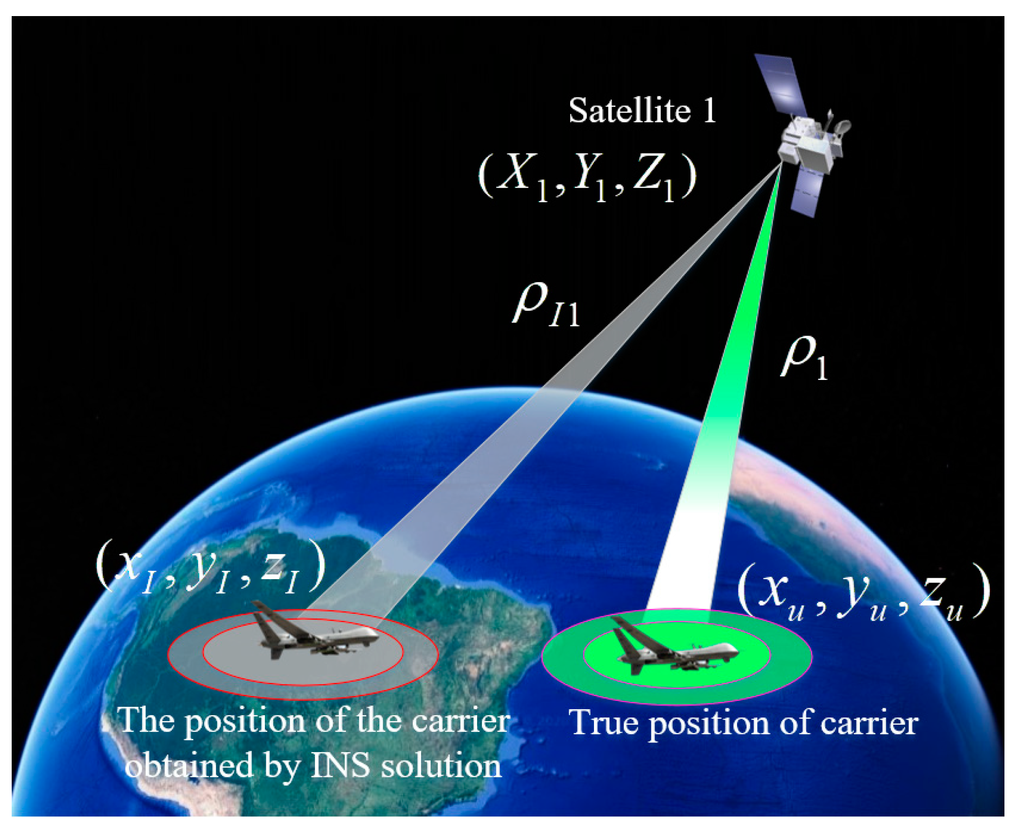
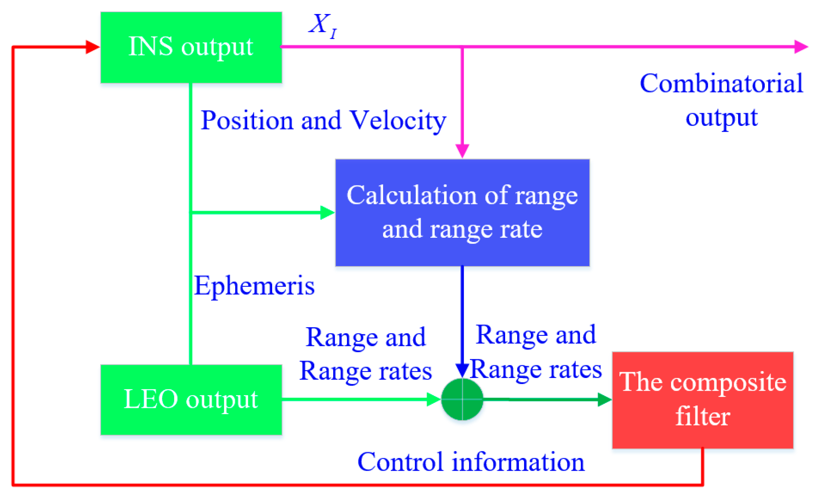
The principle of the INS+LEO 1 satellite integrated navigation algorithm without an altimeter is as follows. First, the ephemeris data provided by the LEO satellite and the position and velocity provided by INS are used to calculate the range and d range rate corresponding to the INS position and velocity. Then, the difference between the range and range rate measured by the LEO satellite and the previously calculated range and range rate is used as the measured value of the INS. At the same time, the optimal estimation of the error between the LEO satellite and INS is obtained by UKF, and finally, the two systems are calibrated. Through this bidirectional auxiliary mode, the INS+LEO 1 satellite integrated navigation mode can work stably for a period of time, basically satisfying the needs of real-time navigation and positioning of aircraft. Figure 3 shows a schematic diagram of the INS+LEO 1 satellite integrated navigation algorithm without an altimeter.
(2)
Algorithm Flow
The flow chart of the INS+LEO 1 satellite integrated navigation algorithm without an altimeter, with an INS/LEO integrated navigation mode based on the range and range rates, is shown in Figure 4.
In this figure, X 1 is the corresponding attitude variable, assuming that the position of satellite 1 in the ECEF coordinate system is ( X 1 , Y 1 , Z 1 ) , the real position of the aircraft in the ECEF coordinate system is ( x u , y u , z u ) , and the position obtained by the INS solution is ( x I , y I , z I ) ; ρ 1 is the real range value of satellite 1; and ρ I 1 is the virtual range value. Therefore,
{ ρ 1 = ( X 1 x u ) 2 + ( Y 1 y u ) 2 + ( Z 1 z u ) 2 ρ I 1 = ( X 1 x I ) 2 + ( Y 1 y I ) 2 + ( Z 1 z I ) 2 .
Then, when obtaining the corresponding range and range rate measurements, the optimal state estimation value can be obtained through the UKF, and the state variable and loop can be updated through the process. Therefore, the INS+LEO 1 satellite navigation and positioning algorithm can be realized.

2.2.3. INS+LEO 1 Satellite + Altimeter Integrated Navigation Algorithm

(1)
Algorithm Principle
According to the principle of the minimum geometric dilution precision (DOP) value, we can select two satellites with the best spatial distribution and visible at any time on the aircraft, and name one of them satellite 1; the other satellite is a virtual satellite named satellite 2. At any time, the aircraft has only the real range value of one satellite, but two satellite range values participate in INS integrated navigation filtering, one of which is the range value of satellite 1, and the other is measured by an altimeter fixed to the carrier. The altimeter can measure the altitude of the carrier, and the altitude plus the radius of the earth can obtain the corresponding satellite range value, in order to realize INS+LEO 1 satellite + altimeter integrated navigation and positioning. Figure 5 shows a schematic diagram of the INS+LEO 1 satellite + altimeter tightly integrated navigation algorithm.
(2)
Algorithm Flow
Suppose that the position of satellite 1 in the ECEF coordinate system is ( X 1 , Y 1 , Z 1 ) , the real position of the aircraft in the ECEF coordinate system is ( x u , y u , z u ) , the altitude measured by the altimeter is h , and the radius of the earth is R e . The real range value of satellite 1 is ρ 1 , and the true range value corresponding to the altimeter is ρ 2 . Therefore,
{ ρ 1 = ( X 1 x u ) 2 + ( Y 1 y u ) 2 + ( Z 1 z u ) 2 ρ 2 = R e + h ρ I 1 = ( X 1 x I ) 2 + ( Y 1 y I ) 2 + ( Z 1 z I ) 2 ρ I 2 = ( 0 x I ) 2 + ( 0 y I ) 2 + ( 0 z I ) 2 .
After obtaining the corresponding range and range rate measurements, the optimal state estimation can be obtained through UKF, and the state variables can be updated. Looping through the process, the integrated navigation algorithm of INS+LEO 1-satellite + altimeter can be realized.

3. Parameter Modeling and Error Analysis of the INS and GNSS Systems

Before the research on the LEO navigation algorithm, it is necessary to analyze and model the error of INS and GNSS systems, because it plays an important role in the reasonable setting of the parameters of algorithms and influences engineering implementation.

3.1. Inertial Navigation Error Analysis and Modeling

Because the strapdown INS (SINS) has the advantages of a small volume, low cost, high precision, and vibration resistance in the environment, we can analyze the SINS from the perspective of a low cost, ease of use, and ease of realization in engineering. In SINS, the sources of error include element error, component installation error, interference error, etc. The most important error sources are gyro drift and acceleration bias [27]. As a measuring element, the drift of the gyroscope will cause drift of the mathematical platform, which will lead to measurement error of the carrier angular velocity, and finally enter the system after the carrier attitude update. Finally, it will have a great impact on the navigation parameter calculation of the SINS. From now on, INS refers to the SINS, and we do not need to declare this factor.
To quantitatively describe the error model of the INS system, we provide the following explanation.
For the error state variables, we use the north, east, and down orders of the axes in the local navigation frame, that is, the NED coordinate system, to express the error state variables. We set the number of dimensions of the error state variables to 9, which are the error angle ϕ N , ϕ E , and ϕ D (the subscript respectively represents the error along the N, E, and D directions); velocity error δ V N , δ V E , and δ V D ; and position error δ L , δ λ , and δ H .

3.1.1. Platform Error Angle Equation

The attitude of the single-satellite integrated navigation algorithm based on broadband LEO constellation communication links is as follows:
δ ϕ = ω n b n = ω i b n ω i e n ω e n n .
After obtaining the total differential on both sides, the error angle equation is
ϕ ˙ n = δ ω i e n + δ ω e n n ( ω i e n + ω e n n ) × ϕ n + ε p ,
where ω α β γ is the rate of rotation of the β -frame axes with respect to the α -frame axes resolved about the γ -frame axes; among them, α = n , i , e , β = b , e , n , γ = n , n represents the local navigation frame; i represents the Earth-centered inertial frame; e represents the Earth-centered Earth-fixed frame; b represents the body frame; ϕ n represents the error angle in the local navigation coordinate system; and ε p = [ ε N , ε E , ε D ] T represents the drift of each axis of the gyroscope. By expanding Equation (17) and ignoring the second-order infinitesimal expression, we can obtain
{ ϕ ˙ N = δ V E R n + h ω i e δ L sin L ( ω i e sin L + V E R n + h tan L ) ϕ E V N R m + h ϕ D + ε N ϕ ˙ E = δ V N R m + h + ( ω i e sin L + V E R m + h tan L ) ϕ N ( ω i e cos L + V E R n + h ) ϕ D + ε E ϕ ˙ D = δ V E R n + h tan L ( ω i e cos L + V E R n + h sec 2 L ) δ L + ( ω i e cos L + V E R n + h ) ϕ E + V N R m + h ϕ D + ε D
where V N , V E , and V D are the velocities along the NED direction; L , λ , and H respectively represent the latitude, longitude, and altitude; ϕ N , ϕ E , and ϕ D respectively indicate the roll angle, pitch, and yaw angle errors of the carrier; δ V N , δ V E , and δ V D are the north, east, and down velocity errors of the carrier, respectively; δ L is the latitude error of the carrier; ε N , ε E , and ε D represent the first-order Markov drift of the gyroscope in the NED direction; and the angular velocity of the earth is ω i e . The equatorial plane radius of the earth ellipsoid is R e = 6378137 ; the curvature radius of the meridian circle is R m = R e ( 1 e 2 ) / ( 1 e 2 sin 2 L ) 3 / 2 ; the curvature radius of the prime unitary circle is R n = R e / 1 e 2 sin 2 L ; and the ellipticity is e = 1 / 298.257 .

3.1.2. Velocity Error Equation

Since the acceleration and the specific force of the carrier correspond one-to-one, the velocity error equation can be obtained from the specific force error. The specific force equation in the navigation coordinate system is as follows:
v ˙ n = f n ( 2 ω i e n + δ ω e n n ) × V n + g n .
By calculating the total differential on both sides of Equation (19), the velocity error propagation equation can be obtained as
δ v ˙ n = f n × ϕ n + p ( 2 δ ω i e n + δ ω e n n ) × V n ( 2 ω i e n + ω e n n ) × δ V n + δ g n ,
where f n represents the specific force of each axis in the local navigation coordinate system, g is the gravitational acceleration, and p = [ N , E , D ] is the equivalent bias error of the accelerometer in the NED direction. The other parameters are the same as in Equation (17). Expanding Equation (20), and ignoring the second-order infinitesimal expression, we can obtain
{ δ V ˙ N = f D ϕ E f E ϕ D 2 ( ω i e sin L + V E R n + h tan L ) δ V E V D R m + h δ V N V N R m + h δ V D ( 2 ω i e cos L + V E R n + h sec 2 L ) V E δ L + N δ V ˙ E = f N ϕ D f D ϕ N + ( V N R m + h tan L V D R m + h ) δ V E + ( 2 ω i e sin L + V E R n + h tan L ) δ V N ( 2 ω i e cos L + V E R n + h ) δ V D + ( 2 ω i e V N cos L + V N V E R n + h sec 2 L + 2 ω i e V D sin L ) δ L + E δ V ˙ D = f E ϕ N f N ϕ E + 2 ( ω i e cos L + V E R n + h ) δ V E + 2 V N R m + h δ V N 2 ω i e V E δ L sin L + D ,  
where f N , f E , and f D represent north, east, and down specific force components in the navigation coordinate system, respectively, and N , E , and D represent the first-order Markov offsets of the accelerometer in the NED direction.

3.1.3. Position Error Equation

The differential of the curve position with respect to time is
{ L ˙ = V N R m + h λ ˙ = V E R n + h sec L h ˙ = V D .
Since the changes in R m and R n are small, they can be regarded as constant values. Therefore, we can take the total differential of Equation (22), ignoring the second-order infinitesimal expression, and obtain the position error propagation equation as
{ δ L ˙ = δ V N R m + h δ λ ˙ = δ V E R n + h sec L + V E δ L R n + h tan L sec L δ h ˙ = δ V D ,
where f is the measured value of the accelerometer, so the position error is calculated by Equation (23).

3.1.4. Error Analysis of Inertial Elements

The random drift error of the gyroscope is generally composed of constant error, fast drift error, and slow drift error. The constant error always remains a constant value and does not change with time. The model is as follows:
ε ˙ b = 0 .
The remarkable characteristic of fast varying drift error is random high frequency jitter; specifically, the correlation coefficients of the corresponding values at any two time points are 0, which can be modeled as white Gaussian noise:
E [ w g ( t ) w g ( τ ) ] = σ g δ ( t τ ) ,
where σ g is the variance of the white noise.
The change trend of slow drift is relatively slow, and the value of the later time is closely related to the value of the previous time, which is similar to the change law of the Markov process, so we can model it as a first-order Markov process:
ε ˙ r = 1 T r ε r + w r ,
where T r is the correlation time constant and w r is the white noise with a zero mean value.
To summarize, the error model of the gyroscope is as follows:
ε = ε b + ε r + w g .
The error of the accelerometer is similar to the error of the gyroscope, so we do not need to repeat it here.

3.2. GNSS Error Analysis and Modeling

According to the randomness of error characteristics, the positioning error of GNSS can be divided into two parts: Systematic error and random error. The main components of systematic error are ephemeris error, satellite clock error, receiver clock error, and refraction error of the ionosphere and troposphere. The main components of random error are multipath effect error and measurement error [28].
After obtaining the ephemeris parameters of the satellite, the space position of the satellite can be calculated through the given satellite ephemeris. There is often a deviation between this position and the actual space position of the satellite. The range error caused by this position can be expressed as follows:
δ ρ e s = r β s β | r β s β | · u α s β δ r o s o + v β s β | v β s β | · u a s β r o s o δ u o s o + r β s β v β s β | r β s β | | v β s β | · u a s β δ z o s o , β i , e , I ,
where u represents the unit vector and the line-of-sight unit vector, s represents the satellite body coordinate system, and o represents the orbital coordinate system. δ r o s o , δ z o s o , and r o s o δ u o s o are the radial error, lateral error, and track direction error in the orbital coordinate system, respectively; r o s o is the position of the real satellite; r β s β is the projection distance of a point in the general coordinate system under the coordinate system; v β s β is the corresponding velocity; represents the antisymmetric operation; and δ ρ e s is the ephemeris error.

3.2.1. Satellite Clock Error

The core aim of GNSS navigation and positioning is to measure the time from satellite signal transmission to receiving by the user receiver, so the clock error will have a great impact on the positioning accuracy of GNSS. To correct the satellite clock deviation, a clock error model is established as follows:
δ t ( s ) = a 0 + a 1 ( t t 0 ) + a 2 ( t t 0 ) 2 ,
where a 0 , a 1 , and a 2 are the zero offset coefficient, frequency offset coefficient, and frequency drift coefficient of the satellite clock, and t 0 is the reference epoch for correcting the satellite clock.

3.2.2. Ionospheric Delay Error

When the satellite signal reaches the ionosphere, the propagation path and propagation velocity of the signal will be affected by the ionosphere and change accordingly. In this case, if we still use the time measured by the receiver to calculate the geometric distance between the satellite and the receiver, there will be a large deviation, which is the so-called ionospheric delay error [29]. The approximate model is as follows:
I [ 1 ( R cos θ n u a s R + h i ) 2 ] 1 2 ,
where θ n u a s is the elevation angle of the satellite, R is the average radius of the earth, and h i is the average ionospheric altitude.

3.2.3. Tropospheric Delay Error

The troposphere will greatly change the refraction coefficient of satellite navigation signals transmitted in the troposphere, causing signal transmission delays and large errors in the final measured distance [30]. The approximate model is as follows:
T [ 1 ( cos θ n u a s 1.001 ) 2 ] 1 2 .

3.2.4. Multipath Effect Error

When the user receives the satellite signal, the satellite signal reflected by the surrounding objects may also be received by the receiver. In this case, the two signals will interfere, and there is a certain deviation between the observed value and the real value, which is the source of the multipath effect [31]. In practical engineering, we can reduce the multipath error by choosing the right station, choosing the appropriate GNSS receiving antenna, and prolonging the observation time. Since the multipath model is more complicated, we will not discuss it here. Our algorithm assumes that the multipath error is a constant within a reasonable range.

4. State Modeling of a Single-Satellite Integrated Navigation Positioning Algorithm Based on Broadband LEO Constellation Communication Links

Since the loose combination requires the GNSS solution result, at least four visible satellites are required. In some places, due to occlusion or a challenging environment, the number of visible satellites cannot be satisfied. At this time, the loose combination cannot be used. However, the close combination is a high-level combination mode. In the close combination mode, not only will the GNSS correct the INS, but the INS will also correct the GNSS. This bidirectional auxiliary method makes the positioning accuracy significantly higher than the positioning accuracy of the loose combination. Even if the number of visible satellites is fewer than four, the tightly integrated mode can work stably for a period of time.
Therefore, to match our algorithm, we use tight integrated navigation to analyze and employ the UKF algorithm for filtering.

4.1. State Equation of Single-Satellite Integrated Navigation and Positioning Algorithm Based on Broadband LEO Constellation Communication Links

When designing the algorithm of an integrated navigation system, we usually use the indirect filtering method. The state variables of the system include two parts, namely, the error of INS and the error of GNSS. However, the scene applied to the integrated navigation algorithm in this paper is the three-dimensional position navigation and positioning of aircraft under a LEO constellation. Since the state equation of GNSS is similar to that of INS, only INS error is listed here.
In the process of selecting the state variables of the INS state equation, according to Section 3.1, the attitude error, velocity error, position error of INS, first-order Markov drift, and Markov offset of the gyroscope and accelerometer can be gathered together to obtain the state variables as follows:
X I = [ ϕ N , ϕ E , ϕ D , δ V N , δ V E , δ V D , δ L , δ λ , δ h , ε N , ε E , ε D , N , E , D ] T ,
where δ λ and δ h denote the longitude error and altitude error, respectively.
The error state equation of INS is as follows:
X ˙ I ( t ) = F I ( t ) X I ( t ) + G I ( t ) W I ( t ) .
The 15-dimensional state variables X I ( t ) are shown in Equation (32), and the process noise vector is
W I ( t ) = [ ω g N , ω g E , ω g D , ω a N , ω a E , ω a D ] T ,
where ω g N , ω g E , and ω g D represent the random drift noise of the gyroscope in the NED direction, and ω a N , ω a E , and ω a D represent the random drift noise of the accelerometer in the NED direction.
The state transition matrix F I ( t ) is a 15 × 15 -dimensional parameter matrix, and G I ( t ) is a 15 × 6 -dimensional noise driving matrix.
Similarly, the noise drive matrix G I ( t ) is as follows:
G I ( t ) = [ C b n O 3 × 3 O 3 × 3 C b n I 3 × 3 O 3 × 3 I 3 × 3 O 3 × 3 O 3 × 3 I 3 × 3 ] 15 × 6 .
According to the above analysis, the state equation of the INS is as follows:
X ˙ I ( t ) = F ( t ) X ( t ) + G ( t ) W ( t ) ,
where X = X I , F = F I , G = G I and W = W I .

4.2. Observation Equation of Single-Satellite Integrated Navigation and Positioning Algorithm Based on Broadband LEO Constellation Communication Links

Generally, the loose combination observation equation is based on the position and velocity combination, and the close combination observation equation is based on pseudorange and pseudorange rates. For the aircraft navigation and positioning in the incomplete observation mode of GNSS, the loose combination mode is not applicable. Therefore, the single-satellite integrated navigation and positioning algorithm based on broadband LEO constellation communication links adopts the tight combination mode, and the observation equation is introduced below.
In the ECEF coordinate system, the carrier position calculated by INS is assumed to be ( x I , y I , z I ) T , the satellite position calculated by LEO satellite ephemeris is ( x s , y s , z s ) T , and the real position of the carrier is ( x u , y u , z u ) T .
The pseudorange from the carrier to the GNSS satellite obtained by INS is as follows:
ρ I i = ( x I x s i ) 2 + ( y I y s i ) 2 + ( z I z s i ) 2 ,
where the superscript i denotes the i th satellite.
Let Equation (37) be expanded by the Taylor series at the true value. Taking the first and second order derivatives, we can obtain
ρ I i = ρ i + x u x s i ρ i δ x u + y u y s i ρ i δ y u + z u z s i ρ i δ z u ,
where ρ i is the true distance from the carrier to satellite S i .
Let e i x u = x u x s i ρ i , e i y u = y u y s i ρ i , e i z u = z u z s i ρ i . Then, Equation (38) can be expressed as follows:
ρ I i = ρ i + e i x u δ x u + e i y u δ y u + e i z u δ z u .
The pseudorange measured by the GNSS receiver is as follows:
ρ G i = ρ i + b c l + v ρ i ,
where v ρ i is the pseudorange measurement white noise of the i th satellite S i .
According to Equation (39) and Equation (40), the pseudorange difference observation equation of INS and GNSS can be calculated:
δ ρ i = ρ I i ρ G i = e i x u δ x u + e i y u δ y u + e i z u δ z u b c l v ρ i .
According to the previous discussion, the position state variables of the geographical coordinate system are L , λ , and h , while the position state variables of the ECEF coordinate system are x u , y u , and z u . Through the coordinate transformation matrix ( C e n ) T , the transformation of position state variables can be completed. The position expression of the transformed ECEF coordinate system is as follows:
{ x u = L sin λ λ sin L cos λ + ( R n + h ) cos λ cos L y u = L cos λ λ sin L sin λ + ( R n + h ) sin λ cos L z u = λ cos L + [ R n ( 1 e 2 ) + h ] sin L .
Then, after omitting the infinitesimal in Equation (42), the two sides of the equation take the differential at the same time, and the state transfer matrix of the error from the geographical system to the ECEF coordinate system is obtained:
δ C n e = [ ( R n + h ) cos λ sin L ( R n + h ) cos L sin λ cos L cos λ ( R n + h ) sin λ sin L ( R n + h ) cos λ cos L cos L sin λ [ R n ( 1 e 2 ) + h ] cos L 0 sin L ] .
In the GNSS/INS integrated navigation system, if the number of satellites is n , then the pseudorange observation equation obtained from Equation (41) is as follows:
Z ρ = H ρ X + V ρ ,
where
H ρ = [ O n × 6 H ρ 1 O n × 6 H ρ 2 ] ,
H ρ 1 = [ e 1 x u e 1 y u e 1 z u e 2 x u e 2 y u e 2 z u e n x u e n y u e n z u ] δ C n e , H ρ 2 = [ 1 0 1 0 1 0 ] .
In the same way, the pseudorange rate from the carrier to the GNSS satellite calculated by INS is as follows:
ρ ˙ I i = ρ ˙ i + e i x u δ x ˙ u + e i y u δ y ˙ u + e i z u δ z ˙ u = e i x u ( x ˙ u x ˙ s i ) + e i y u ( y ˙ u y ˙ s i ) + e i z u ( z ˙ u z ˙ u i ) + e i x u δ x ˙ u + e i y u δ y ˙ u + e i z u δ z ˙ u
The pseudorange rate that is output by the GNSS receiver can be obtained by deriving the pseudorange ρ G i in Equation (40):
ρ ˙ G i = ρ G i d t = d ( ρ i + b c l + v ρ i ) d t = ρ ˙ i + b ˙ c l + v ˙ ρ i .
By combining Equation (47) with Equation (48), the pseudorange rate difference observation equation of INS and GNSS can be obtained:
δ ρ ˙ i = ρ ˙ I i ρ ˙ G i = e i x u δ x ˙ u + e i y u δ y ˙ u + e i z u δ z ˙ u b ˙ c l v ˙ ρ i .
Similar to the pseudorange error, the velocity error in the geographical coordinate system must be converted into the velocity error in the ECEF coordinate system, as shown in the following formula:
[ δ x ˙ u δ y ˙ u δ z ˙ u ] = C n e [ δ V N δ V D δ V D ] .
By comparing this with Equation (44), the measurement equation of the pseudorange rate can be obtained as follows:
Z ρ ˙ = H ρ ˙ X + V ρ ˙ ,
where
H ρ ˙ = [ O n × 3 H ρ ˙ 1 O n × 9 H ρ ˙ 2 ] ,
H ρ ˙ 1 = [ e 1 x u e 1 y u e 1 z u e 2 x u e 2 y u e 2 z u e n x u e n y u e n z u ] C n e , H ρ ˙ 2 = [ 1 0 1 0 1 0 ] .
By combining the observation equations of the pseudorange and pseudorange rate information, we can obtain the closely combined observation equation:
Z ( t ) = H ( t ) X ( t ) + V ( t ) = [ Z ρ ( t ) Z ρ ( t ) ] = [ H ρ ( t ) X ( t ) + V ρ ( t ) H ρ ( t ) X ( t ) + V ρ ( t ) ] .

5. Simulation Analysis

5.1. Parameter Setting

At present, the main LEO constellations in the world include SpaceX, Oneweb, and Telesat, with no loss in generality. Since the orbital altitude of the Telesat system is in a middle position among many LEO constellations and its high inclination orbit is conducive to covering challenging environments, such as polar regions, we use the 99.5° inclination orbit constellation of the Telesat system for simulation and analysis. The main parameters of the Telesat system are shown in Table 1.
For IMU model parameters, we set the relevant parameters of the accelerometer and gyroscope according to the requirements of a low-cost consumption level or medium level. Among these parameters, the scale factor and cross coupling error of the accelerometer and gyroscope are set at 100~1000 ppm, while the accelerometer bias is set in the range of 10~100 mg, the gyroscope bias is set in the order of 10 7 , and the quantization noise is set as 10 4 m/ s 2 [33]. Regarding the UKF, considering the uncertainty of each axis, we set the initial uncertainty of position and velocity in each axis as 1 m and 0.01 m/s, respectively, and the initial uncertainty of the acceleration level and gyroscope axis are set as 2.9420 × 10 4 and 4.848 × 10 9 , respectively. For the convenience of analysis, we assume that the initial attitude error, initial position error, and initial velocity error of the UKF are 0. In addition, we set the initial position of the aircraft as follows: Latitude, 50.4250° north; longitude, -3.5958° east; and altitude, 10,000 m. The initial velocity along the longitudinal axis of the carrier coordinate system is 200 m/s; the initial roll angle, pitch angle, and yaw angle are 0°, 0°, and 90°, respectively; and the initial errors are all set to 0. At the same time, there are two 45° turns in the opposite direction during the flight of the carrier. The time in the simulation parameters is 418 s, and the sampling interval is 0.01 s.

5.2. Simulation Results

5.2.1. Without Altimeter Scenario

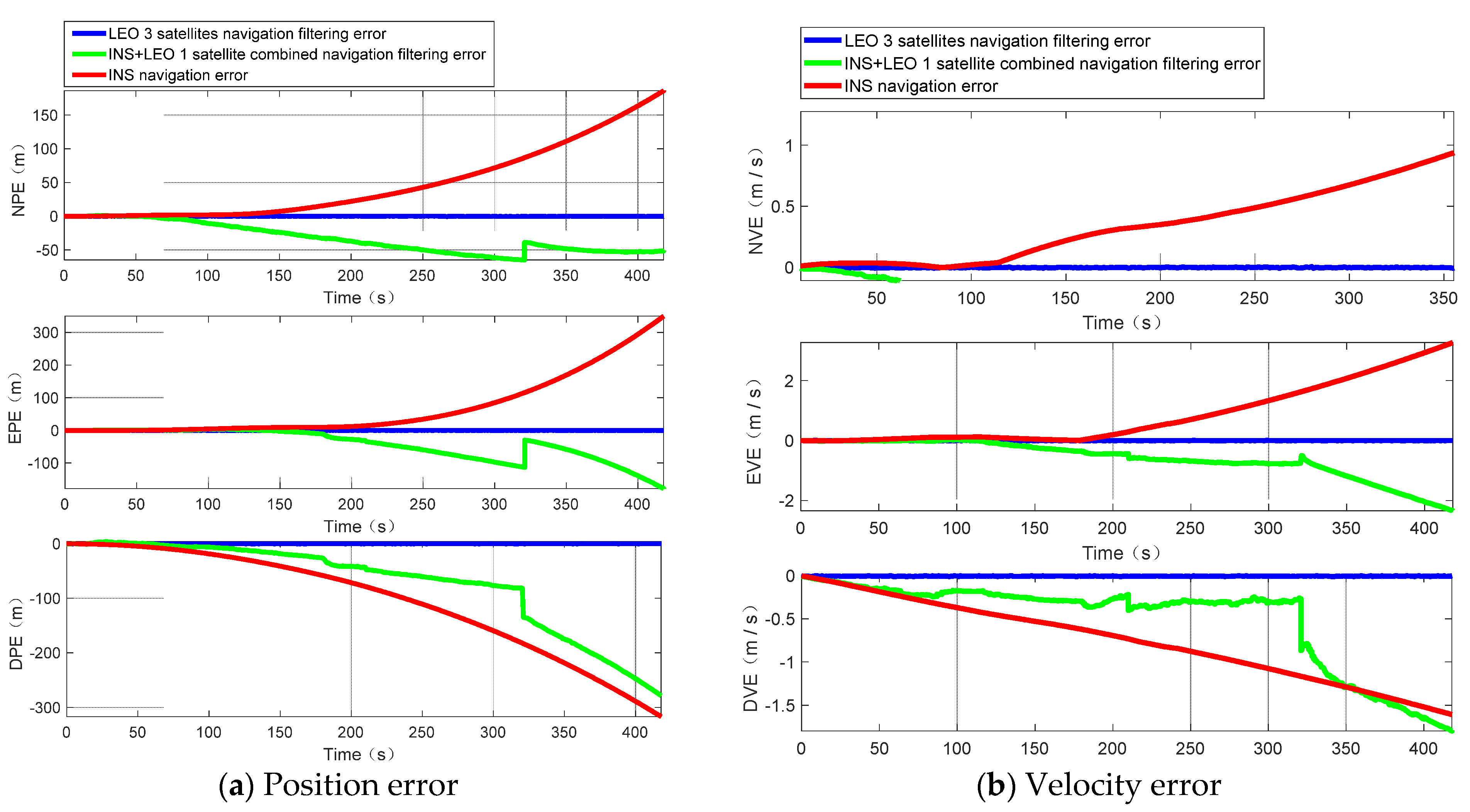
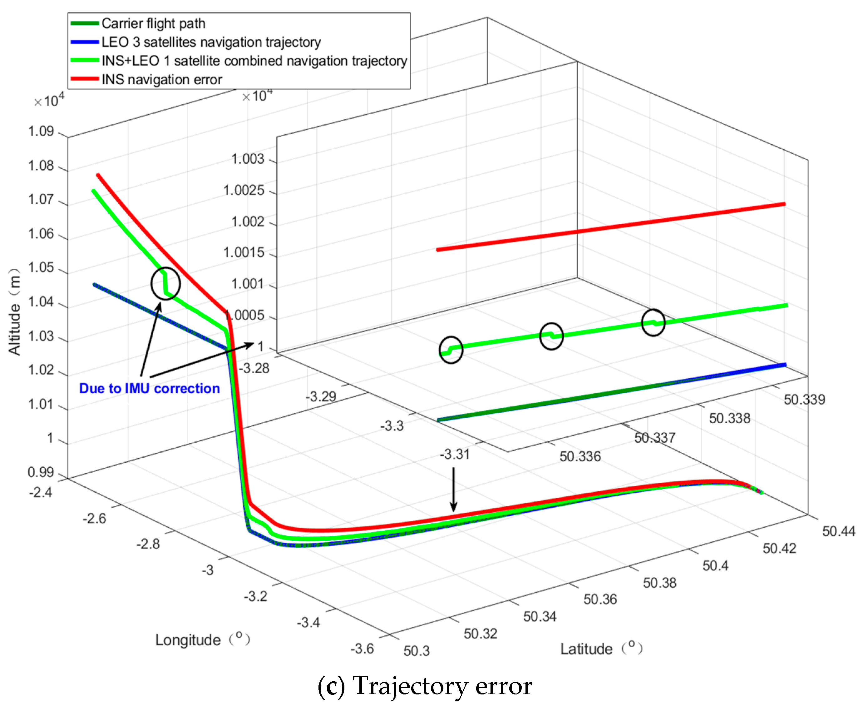
The single-satellite navigation and positioning results in the scenario without an altimeter are shown in Figure 6. We also give the navigation and positioning results of the LEO 3 satellites + LS algorithm as a reference.
Figure 6 shows that, without the aid of an altimeter, the positioning error, velocity error, and navigation trajectory error of LEO 1 satellite + INS are smaller than those in INS alone. To quantitatively analyze and evaluate the positioning error of the LEO 1 satellite + INS, we chose the mean value and standard deviation (STD) to describe the accuracy performance of the algorithm. Table 2, Table 3 and Table 4 show the statistical data of the positioning results of the LEO 1 satellite + INS and INS navigation and the standard LEO 3 satellites + LS algorithm. Among them, NPE stands for north position error, NVE stands for north velocity error, and the meaning of the other acronyms can be deduced by analogy.
From Table 2, Table 3 and Table 4, compared with INS navigation, we find the following:
(1)
In terms of the position error, the position error accuracy of the INS + LEO 1 satellite in the north direction is increased by 31.40%, and the STD is increased by 59.76%; the position error and STD accuracy in the east direction are increased by 37.99% and 50.19%, respectively; and the position error accuracy and STD of the down direction are improved by 32.40% and 15.00%, respectively;
(2)
The accuracy of the INS + LEO 1 satellite in the north direction is improved by 57.34%, and the STD is increased by 70.58%; the velocity error and STD accuracy in the east direction are increased by 28.31% and 37.63%, respectively; and the velocity error accuracy in the earth direction is increased by 33.17%, while the STD is reduced by 12.71%;
(3)
In the final trajectory error, the mean error accuracy of the longitude error is improved by 10.59% and the STD is increased by 38.12%. Since IMU is constantly correcting the navigation error, there are some fluctuations in the latitude error. This result can be seen in Figure 6c. Therefore, the mean and STD of the latitude decrease significantly, but the average accuracy of the altitude error is improved by 32.40% and the STD is increased by 15.00%.
From the above analysis, we can conclude that, in most cases, whether we consider the mean or STD, the navigation and positioning error of the LEO 1 satellite + INS algorithm is better than the navigation and positioning error of INS, satisfying the navigation and positioning needs of the position accuracy within 100 m and velocity error within 2.5 m/s, However, the LEO 1 satellite + INS algorithm cannot overcome the divergence of INS. In challenging environments that require a high accuracy, such as indoor and urban environments, this positioning result is difficult for people to accept. From Table 2, Table 3 and Table 4, compared with INS navigation, we find the following:
(1)
In terms of the position error, the position error accuracy of the INS + LEO 1 satellite in the north direction is increased by 31.40%, and the STD is increased by 59.76%; the position error and STD accuracy in the east direction are increased by 37.99% and 50.19%, respectively; and the position error accuracy and STD of the down direction are improved by 32.40% and 15.00%, respectively;
(2)
The accuracy of the INS + LEO 1 satellite in the north direction is improved by 57.34%, and the STD is increased by 70.58%; the velocity error and STD accuracy in the east direction are increased by 28.31% and 37.63%, respectively; and the velocity error accuracy in the earth direction is increased by 33.17%, while the STD is reduced by 12.71%;
(3)
In the final trajectory error, the mean error accuracy of the longitude error is improved by 10.59% and the STD is increased by 38.12%. Since IMU is constantly correcting the navigation error, there are some fluctuations in the latitude error. This result can be seen in Figure 6c. Therefore, the mean and STD of the latitude decrease significantly, but the average accuracy of the altitude error is improved by 32.40% and the STD is increased by 15.00%.
From the above analysis, we can conclude that, in most cases, whether we consider the mean or STD, the navigation and positioning error of the LEO 1 satellite + INS algorithm is better than the navigation and positioning error of INS, satisfying the navigation and positioning needs of the position accuracy within 100 m and velocity error within 2.5 m/s, However, the LEO 1 satellite + INS algorithm cannot overcome the divergence of INS. In challenging environments that require a high accuracy, such as indoor and urban environments, this positioning result is difficult for people to accept.

5.2.2. Altimeter Scene

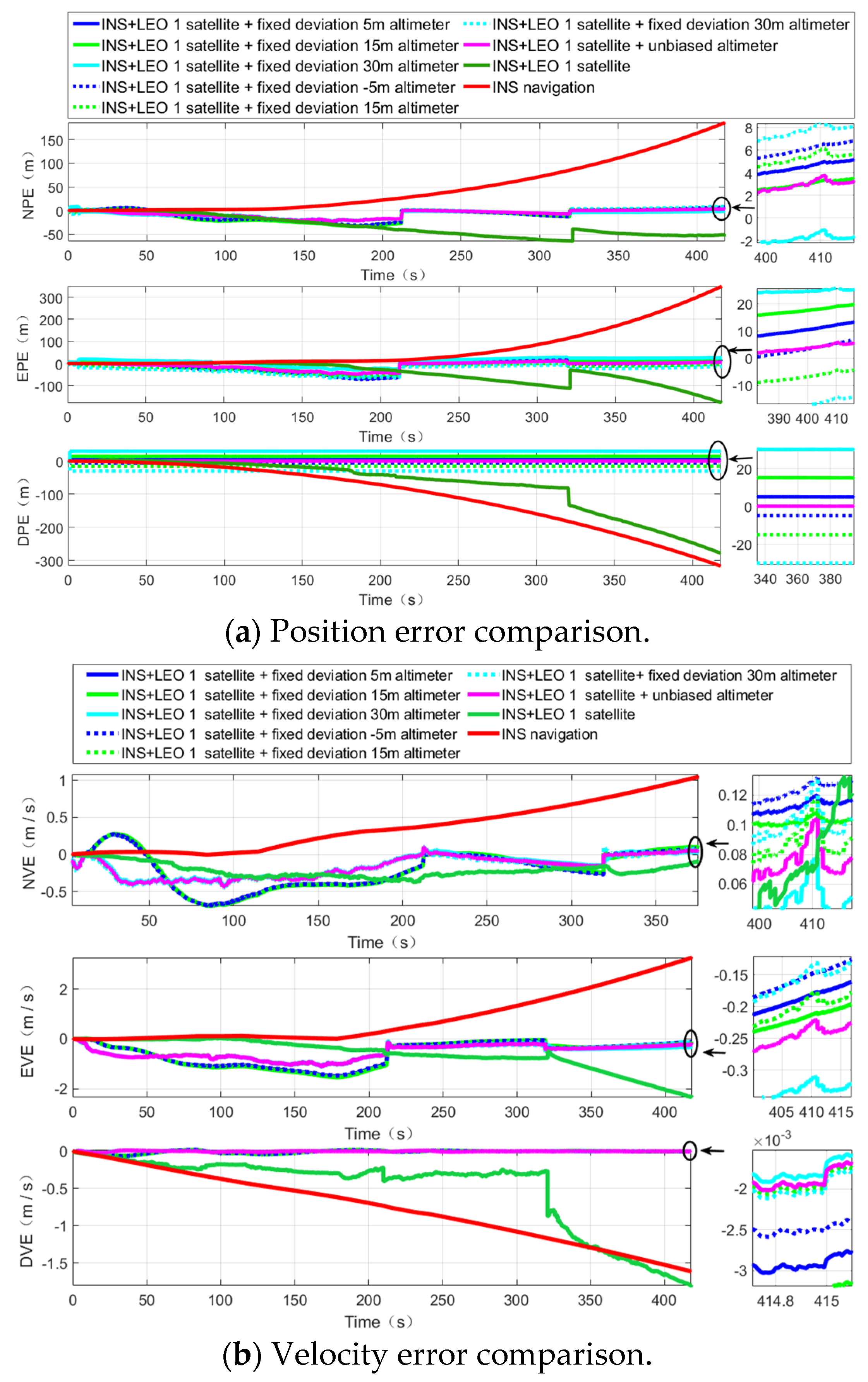
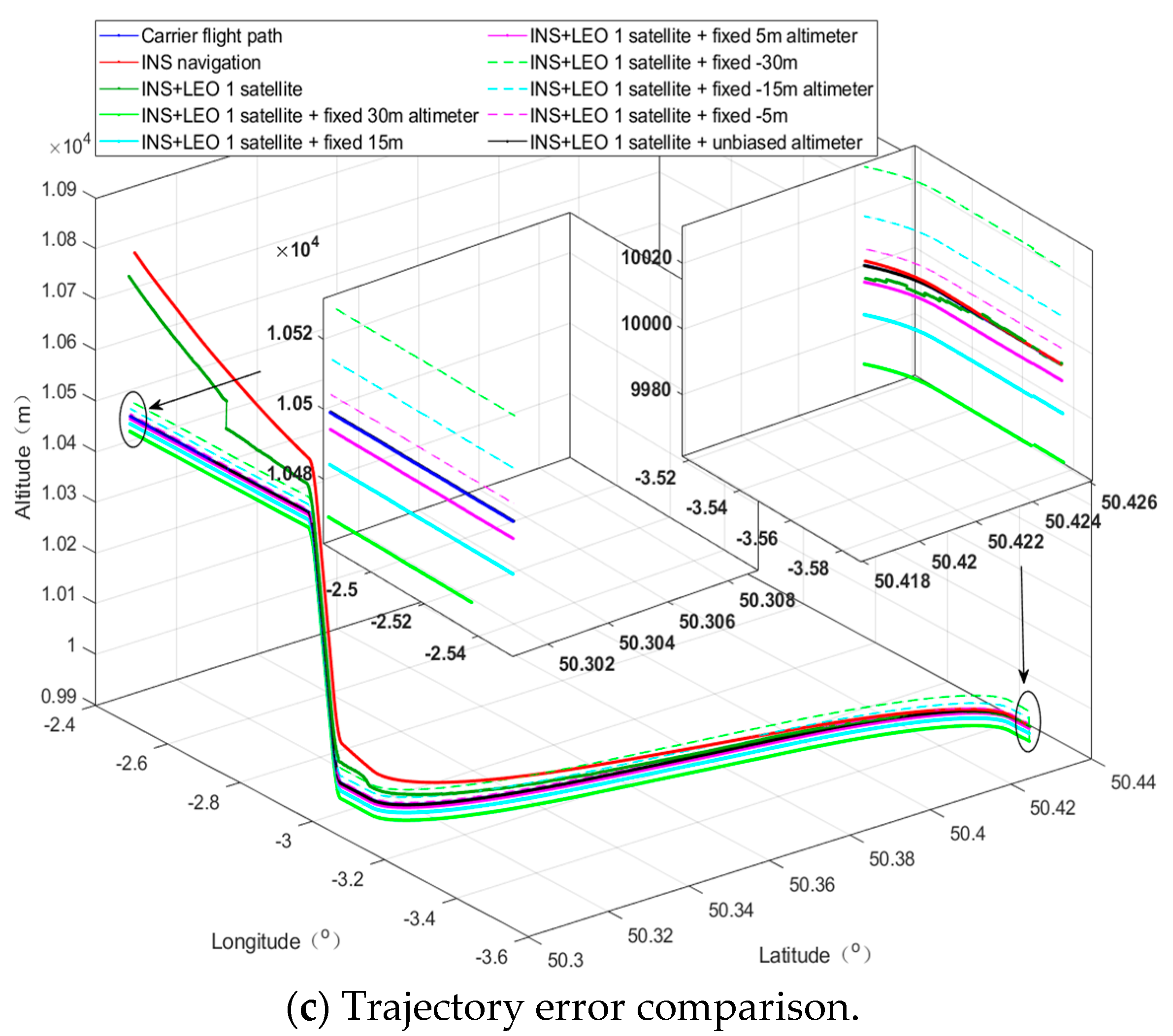
To overcome the problem of the low positioning accuracy in the LEO 1 satellite + INS algorithm, we introduced an altimeter on the basis of the algorithm. In the altimeter scene, according to the altimeter deviation, we divided the altimeter scene into three types: The altimeter no deviation scene; the fixed deviation 30, 15, and 5 m scenes; and the fixed deviation −30, −15, and −5 m scenarios for comparative analysis. The simulation results are shown in Figure 7.
Figure 7 shows that the LEO 1 satellite + INS + altimeter algorithm can significantly improve the navigation and positioning accuracy and solve the problem of INS divergence. Similarly, in the altimeter scene, we calculated and counted the mean and variance of navigation and positioning results, and the results are shown in Table 5, Table 6 and Table 7. Without losing generality, we only counted the altimeter without deviation scene, fixed deviation 30 m scene, and fixed deviation −30 m scene, and when the altimeter deviation was ± 15 and ± 5 m, the same conclusion could be obtained.
According to Table 5, Table 6 and Table 7, we can observe that the positioning error of the LEO 1 satellite + INS algorithm was significantly reduced due to the addition of altimeters. In the case of no deviation altitude, relative to INS navigation error,
(1)
The average position error of the north direction is increased from 31.40% to 86.00%, the accuracy of STD is improved from 59.76% to 85.17%, the average position error of the east direction is increased from 37.99% to 85.86%, the accuracy of STD is improved from 50.19% to 81.25%, the mean value of the down position error is increased from 32.40% to almost 100% (indicating that the error is almost reduced to 0), and the accuracy of STD is increased from 15.00% to 99.98%;
(2)
The mean value of the north velocity accuracy is increased from 57.34% to 68.87%. However, due to the continuous correction of inertial navigation, the STD accuracy drops from 70.58% to 60.15%, but the mean value of the east velocity error increases from 28.31% to 37.24%, and the accuracy of STD increases from 37.63% to 71.67%, and the mean value of down velocity error is increased from 33.17% to 99.94%. Obviously, the accuracy of STD is improved from 12.71% lower than INS navigation to 98.78%;
(3)
In terms of the final trajectory error, the mean error accuracy of longitude error is increased from 10.59% to 81.77%, and the STD is increased from 38.12% to 77.21%; the latitude error accuracy mean and STD accuracy are improved by 77.13% and 62.27%, respectively; the mean value of the altitude error accuracy has increased from 32.40% to almost 100%; and the STD has increased from 15.00% to 99.98%.
From the above qualitative and quantitative analysis, we can find that due to the addition of altimeters, the positioning error of the LEO 1 satellite + INS + altimeter algorithm has been significantly improved. Taking the mean value as an example, the position error is reduced from the 100 to 10 m level. Especially in the case of no deviation altimeter, the error can be reduced to a sub mm level. Even if the altimeter has a deviation, after deducting the fixed deviation, the average error is 0.0730 m (altimeter fixed deviation is 30 m) and 0.0714 m (altimeter fixed deviation is −30 m), and the positioning accuracy reaches the cm level. The INS position divergence can be effectively suppressed. Similarly, the velocity error has also been significantly improved. The longitude, latitude, and altitude accuracy mean and STD of the final navigation trajectory have also been greatly improved, especially the mean and STD of the altitude error, which decreased from 70.4270 and 309.3698 m without an altimeter to 29.9286 and 1.4617 m under the altimeter scene, respectively. The variance is more concentrated, which indicates that the navigation system is more stable and robust.

5.2.3. Comparison with MEO Constellation Algorithms

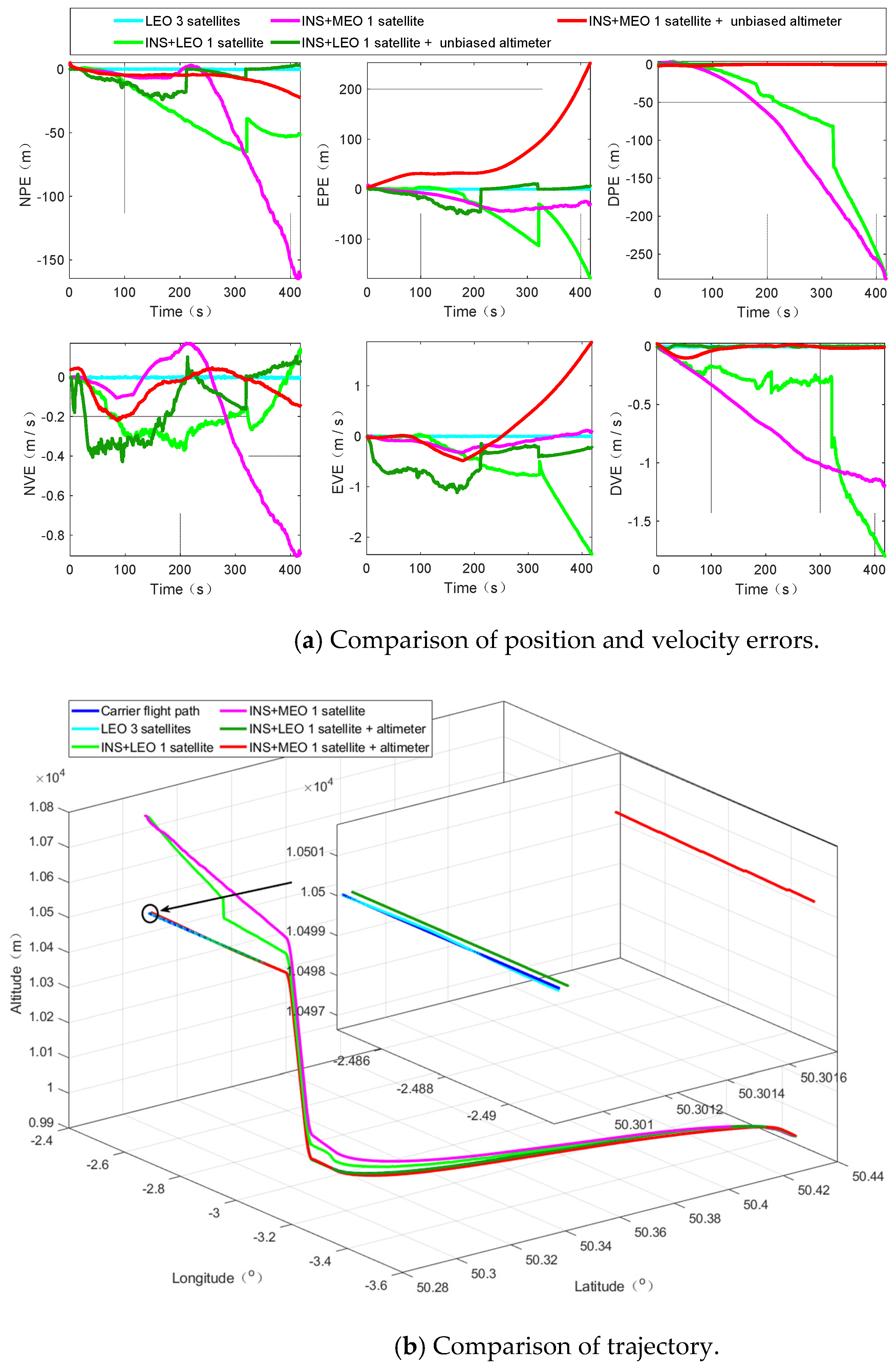
To compare the navigation and positioning performance of LEO and MEO constellations, we compared and analyzed the navigation and positioning results in LEO and MEO scenarios under the condition of reasonable setting parameters, without a loss of generality. We focused on a comparison of LEO 1 satellite + altimeter and MEO 1 satellite + altimeter integrated navigation and positioning. Figure 8 shows the navigation and positioning results of the LEO and MEO constellations.
As Figure 8 shows, in the situation without an altimeter, although the error of longitude is relatively large, the navigation result in the LEO constellation is smaller than the navigation result in the MEO constellation. In the altimeter scene, both LEO constellation navigation and MEO constellation navigation, position, velocity, and trajectory errors are significantly improved, and the improvement effect under the LEO constellation is more obvious than the improvement under the MEO constellation. It is also more effective to overcome the divergence of INS. To quantitatively analyze the navigation performance of the LEO and MEO constellations, we calculated statistics on the navigation error results of MEO, as shown in Table 8, Table 9 and Table 10. LEO navigation error statistics can be found in Table 2, Table 3, Table 4, Table 5, Table 6 and Table 7.
According to Figure 8, we can find that compared with the INS and MEO 1 satellite + altimeter, the LEO 1 satellite + altimeter can effectively overcome the divergence of INS. Compared with standard LEO 3 s positioning, although LEO 1 satellite + altimeter has fluctuations in local details, the final navigation trajectory is very close to the real trajectory of the aircraft. The STD of the trajectory error is 0.0182 m, reaching a cm level, and its positioning error is similar to the standard LEO, which shows that the LEO constellation is more suitable for the algorithm proposed by us and verifies the superiority of the LEO constellation as a navigation system. It is not difficult to imagine that its advantages are self-evident compared with the high orbit constellation.
From Table 8, Table 9 and Table 10, compared with the MEO 1 satellites + INS algorithm, we can find the following:
(1)
In the scenario without an altimeter, since the LEO constellation has less pseudorange measurement noise and pseudorange rate measurement noise than the MEO constellation, the LEO constellation is more sensitive to the UKF algorithm. As a result, the overall performance of the LEO constellation algorithm in some directions is slightly worse than the overall performance of the MEO constellation, but the overall performance of the LEO constellation algorithm is still better than the overall performance of the MEO constellation algorithm.
(2)
In the scenario of an altimeter, the performance of the LEO constellation algorithm is significantly better than the performance of the MEO1 constellation algorithm, especially in the down direction. Position and velocity errors have absolute advantages, and the accuracy of the mean is increased by 99.85% and 97.36% and STD is increased by 97.67% and 82.08%, respectively. In the final trajectory error, the mean value and STD of the altitude accuracy are increased by 99.96% and 99.49%, respectively.
From the above analysis, we can find that, due to the inherent characteristics of system error, such as the pseudorange measurement noise and pseudorange rate measurement noise of the LEO constellation and the MEO constellation, the position error of the MEO constellation in a certain direction may be slightly lower than the position error of the LEO constellation. However, due to the long period of time it takes for the MEO satellite to pass the zenith, the geometric accuracy characteristics cannot be updated quickly. Therefore, the MEO satellite is unable to overcome the divergence problem of INS. In comparison, the LEO constellation does not have such problems, so it is more suitable for the navigation and positioning requirements under the integration of communication and navigation, and the LEO constellation can effectively improve the accuracy of navigation and positioning without much cost.

5.2.4. Comparison with Traditional Algorithms

To compare it with the traditional single-satellite navigation and positioning algorithm, because the velocity and attitude are not easy to compare due to the specific carrier characteristics, we focus on the comparison of position error and trajectory error. We selected reference [20] and reference [19] for comparison.
(1)
Position Error Comparison
Since the positioning error caused by the initial error will eventually be corrected by the system and the algorithm, we ignored the impact of the initial error and compared and analyzed the final effect of our algorithm and the algorithm proposed in reference [20]. We collated the positioning accuracy error of our proposed algorithm and the accuracy error proposed in reference [20] in Table 11.
From Table 11, we can find that, compared with the algorithm proposed in [20], the mean of the position accuracy in the north and east directions is increased by 97.31% and 96.24%, and the STD is increased by 98.52% and 96.40%, respectively, while the mean and STD of the ground accuracy are almost 100% improved (that is, the error is reduced to almost 0). Combined with Table 6, even if there is deviation in the altimeter, for example, the deviation is 30 m, the mean and STD of the down position accuracy can also be increased by 100%. Regardless of whether the mean or STD is considered, in the north, east, and down directions, the error of our algorithm is much smaller than the error of the algorithm proposed in the literature [20], and our algorithm is more suitable for navigation and positioning in challenging situations.
(2)
Trajectory Error Comparison
The final trajectories of our algorithm and the algorithm proposed in reference [19] were compared and analyzed, and the statistics of relevant results are shown in Table 12.
From Table 12, we can find that, compared with the algorithm proposed in reference [19], our algorithm can increase the longitude accuracy by 99.94%, latitude accuracy by 96.24%, and altitude accuracy by almost 100%, and the STD increased by 82.31%, 77.69%, and 99.88%, respectively. The accuracy is significantly improved compared to the algorithm proposed in the literature [19], also proving that our algorithm is more suitable for navigation and positioning in challenging situations.

5.3. Discussion

According to the above simulation and analysis results, we will present a brief analysis and discussion, as follows:
(1)
Compared with INS navigation, the usability of our algorithm is obviously better than INS in the scenario without an altimeter and in the scenario with an altimeter, but in the scenario without an altimeter, the variance is relatively large, and there is the problem of INS divergence;
(2)
To overcome the problem of INS divergence, we have introduced an altimeter to improve this problem. We can find that, in the scene of an unbiased altimeter, our algorithm can significantly improve the position and velocity accuracy in all directions and the final trajectory accuracy, especially the altitude accuracy. In addition, even if the altimeter exhibits deviation, the positioning accuracy can reach a cm level, and the divergence of INS can be effectively overcome;
(3)
Compared with the scene without an altimeter, for the algorithm in the scene of an altimeter, the position accuracy, velocity accuracy, and final trajectory accuracy are significantly improved, which shows that in the specific engineering application, the introduction of an altimeter will improve the robustness of the whole navigation system, especially the barometric altimeter with smaller altitude deviation;
(4)
Compared with the MEO constellation, the navigation trajectory of LEO constellation is closer to the real trajectory of aircraft, and it can effectively overcome the divergence problem of INS, so the LEO constellation is more suitable for the preferred constellation of the PNTRC scheme;
(5)
Compared with the traditional algorithm, each index accuracy has improved by more than 95%, which is enough to explain the progressiveness of our algorithm, because it can achieve such a high positioning accuracy without continuous observation, and there is no positioning delay, so it satisfies the real-time, high-precision positioning needs in challenging environments.

6. Results

This paper presents a low-cost, high engineering ease-of-use, and strong anti-jamming capability tool for the high-precision and real-time positioning requirements in challenging environments. Our algorithm is based on the LEO giant constellation. It has a realistic material basis and actual needs. Space X, OneWeb, and Telesat are intensively conducting research and subsequent prototype satellite launches, striving to achieve seamless internet interconnection in any corner of the world and high-precision positioning at a cm level.
Through our research, we can find that, even in the scenario without an altimeter, our algorithm can provide basic location services; when combined with an altimeter, it can effectively overcome the divergence problem of INS and significantly improve the navigation and positioning accuracy in challenging environments, and when the altimeter deviation is small, the positioning accuracy can be further improved. With the advancement of modern electronic technology, it is not difficult to obtain an altimeter with a smaller deviation; in addition, we also verified from the perspective of simulation that the LEO constellation is more suitable for the implementation of the PNTRC scheme, which benefits from the advantages and potential advantages of the LEO constellation. Compared with the traditional single-satellite positioning algorithm, our algorithm is an implementation scheme of PNTRC, which eliminates the clock bias. Additionally, there is no need to exchange time redundancy for spatial redundancy for positioning, there is no positioning delay, and the positioning accuracy is significantly better than that of traditional algorithms.
Therefore, there are various signs that our algorithm can satisfy the requirement for location services in challenging environments, such as lush forests, canyons, cities with towering buildings, etc.
Author Contributions

Y.Y. and L.Y. conceived the conceptualization and algorithm L.Y. completed the implementation of the algorithm and the writing of the paper, and supported the writing—review and editing. X.J. completed some preliminary simulations, and did preliminary research and summary. J.M. and L.D. review the experimental results and give formal analysis and suggestions. H.L. provides theoretical guidance and suggestions for revision of the paper. All authors have read and agreed to the published version of the manuscript.

Funding

Funding was supported by the National Key Research and Development Program of China (Grant Nos.2017YFC1500904, 2016YFB0501301) and National 973 Program of China (Grant Nos.613237201506).

Data Availability Statement

Not applicable.

Conflicts of Interest

The authors declare no conflict of interest.

References

  1. Reid, T.G.; Neish, A.M.; Walter, T.; Enge, P.K. Broadband LEO Constellations for Navigation. Navigation 2018, 65, 205–220. [Google Scholar] [CrossRef]
  2. Del, P.I.; Cameron, B.G.; Crawley, E.F. A technical comparison of three low earth orbit satellite constellation systems to provide global broadband. Acta Astronaut. 2019, 159, 123–135. [Google Scholar]
  3. Li, D.; Shen, X.; Li, D.; Li, S. On civil-military integrated space-based real-time information service system. Geomat. Inf. Sci. Wuhan Univ. 2017, 42, 1501–1505. [Google Scholar]
  4. Luo, R.; Yuan, H.; Xu, Y. Navigation Augmentation based on LEO Communication Satellite Constellations. In Proceedings of the 2018 International Technical Meeting of the Institute of Navigation, Reston, VA, USA, 29 January–1 February 2018; pp. 188–195. [Google Scholar]
  5. Qiu, D.; De Lorenzo, D.S.; Bhattacharya, T. Indoor geo-location with cellular RF pattern matching and LEO communication satellite signals. In Proceedings of the Institute of Navigation International Technical Meeting, San Diego, CA, USA, 28–30 January 2013; pp. 726–733. [Google Scholar]
  6. Cui, J.; Shi, H. Satellite Communication and Navigation Integrated Signal. Telkomnika Indones. J. Electr. Eng. 2013, 11, 4351–4356. [Google Scholar] [CrossRef]
  7. Meng, Y.; Bian, L.; Han, L.; Lei, W.; Yan, T.; He, M.; Li, X. A Global Navigation Augmentation System Based on LEO Communication Constellation. In Proceedings of the 2018 European Navigation Conference (ENC), Gothenburg, Sweden, 14–17 May 2018; pp. 65–71. [Google Scholar]
  8. Ma, J.; Yang, Y.; Li, H.; Li, J. FH-BOC: Generalized low-ambiguity anti-interference spread spectrum modulation based on frequency-hopping binary offset carrier. GPS Solut. 2020, 24, 1–16. [Google Scholar] [CrossRef]
  9. Chan, Y.T.; Towers, J.J. Passive localization from Doppler-shifted frequency measurements. IEEE Trans Signal Process. 1992, 40, 2594–2598. [Google Scholar] [CrossRef]
  10. Fowler, M.L. Analysis of single-platform passive emitterlocation with terrain data. IEEE Trans Aerosp. Electron. Syst. 2001, 37, 495–507. [Google Scholar] [CrossRef]
  11. Wu, N.E.; Fowler, M.L. Aperture error mitigation via local-state estimation for frequency-based emitter location. IEEE Trans Aerosp. Electron. Syst. 2003, 39, 414–429. [Google Scholar] [CrossRef]
  12. Shang, C.H. Research High-Precision Measurement of Doppler in Passive Location by Single Satellite; Beijing Institute of Technology: Beijing, China, 2015. [Google Scholar]
  13. Zhu, Y.F.; Zhang, S.S. Passive Location Based on an Accurate Doppler Measurement by Single Satellite. In Proceedings of the 2017 IEEE Radar Conference (Radar Conf), Seattle, WA, USA, 8–12 May 2017; pp. 1424–1427. [Google Scholar]
  14. Roecker, J.A. On combining multidimensional target location ellipsoids. IEEE Trans Aerosp. Electron. Syst. 1991, 27, 175–177. [Google Scholar] [CrossRef]
  15. Liu, D.; Tang, C.; Zhang, Y. UKF-based INS/single-satellite Navigation Dynamic Positioning Algorithm. In Proceedings of the 2018 IEEE International Conference on Signal Processing, Communications and Computing (ICSPCC), Qingdao, China, 14–16 September 2018; pp. 1–4. [Google Scholar]
  16. Caiyong, H.; Heng, L. Method of single satellite passive geolocation using spatial sparsity. Telecommun. Sci. 2016, 32, 65. [Google Scholar]
  17. Morales, J.; Khalife, J.; Kassas, Z.M. Simultaneous Tracking of Orbcomm LEO Satellites and Inertial Navigation System Aiding Using Doppler Measurements. In Proceedings of the 2019 IEEE 89th Vehicular Technology Conference (VTC2019-Spring), Kuala Lumpur, Malaysia, 28 April–1 May 2019; pp. 1–6. [Google Scholar]
  18. Deng, Z.; Fan, G.; He, C. Research on Doppler Locating Method of LEO Satellite Backup Navigation System. In China Satellite Navigation Conference (CSNC); Springer: Berlin/Heidelberg, Germany, 2017; pp. 487–496. [Google Scholar]
  19. Hsu, W.H.; Jan, S.S. Assessment of using Doppler shift of LEO satellites to aid GPS positioning. In Proceedings of the 2014 IEEE/ION Position, Location and Navigation Symposium-PLANS 2014, Monterey, CA, USA, 5–8 May 2014; pp. 1155–1161. [Google Scholar]
  20. Jiaqi, L.; Yi, Z.; Chengkai, T.; Xingxing, Z. INS aided High Dynamic Single-Satellite Position Algorithm. In Proceedings of the 2019 IEEE International Conference on Signal Processing, Communications and Computing (ICSPCC), Dalian, China, 20–22 September 2019; pp. 1–5. [Google Scholar]
  21. Liu, D.; Zhang, Y.; Tang, C. A single—Satellite navigation and positioning algorithm based on inertial navigation under emergency conditions. In Proceedings of the 9th China Satellite Navigation Conference (CSNC), Beijing, China, 24 May 2018; pp. 1–7. [Google Scholar]
  22. Xie, G. Principle of GNSS: GPA, GLONASS, and Galileo; Publishing House of Electronics Industry: Beijing, China, 2013; p. 266. [Google Scholar]
  23. Konatowski, S.; Kaniewski, P.; Matuszewski, J. Comparison of Estimation Accuracy of EKF, UKF and PF Filters. Annu. Navig. 2016, 23, 69–87. [Google Scholar] [CrossRef] [Green Version]
  24. Kang, C.H.; Kim, S.Y.; Park, C.G. Adaptive complex-EKF-based DOA estimation for GPS spoofing detection. IET Signal Process. 2018, 12, 174–181. [Google Scholar] [CrossRef]
  25. Van Der Merwe, R.; Wan, E.A. The square-root unscented Kalman filter for state and parameter-estimation. In Proceedings of the IEEE International Conference on Acoustics, IEEE Computer Society, Salt Lake City, UT, USA, 7–11 May 2001. [Google Scholar]
  26. Risfic, B.; Arulampalam, S.; Gordon, N. Beyond the kalman filter—Book Review. IEEE Aerosp. Electron. Syst. Mag. 2004, 19, 37–38. [Google Scholar] [CrossRef]
  27. Groves, P.D. Principles of GNSS, inertial, and multisensor integrated navigation systems. Ind. Robot 2013, 67, 191–192. [Google Scholar]
  28. Groves, P.D. Principles of GNSS, Inertial, and Multisensor Integrated Navigation Systems, 2nd ed.; Artech House: Fitchburg, MA, USA, 2012; 776p, ISBN 978-1-60807-005-3. [Google Scholar]
  29. Elliott, K.; Christopher, H. Understanding GPS: Principles and Applications, 2nd ed.; Artech House: Fitchburg, MA, USA, 2006; 703p, ISBN 1-58053-894-0. [Google Scholar]
  30. Misra, P. Global Positioning System: Signal, Measurement, and Performance, 2nd ed.; Ganga-Jamuna Press: Nagpur, India, 2011; 590p, ISBN 978-0970954428. [Google Scholar]
  31. Brach, M.; Stereńczak, K.; Bolibok, L.; Kwaśny, Ł.; Krok, G. Impacts of forest spatial structure on variation of the multipath phenomenon of navigation satellite signals. Folia For. Pol. Ser. A 2019, 51, 3–21. [Google Scholar] [CrossRef] [Green Version]
  32. Gruber, B. GPS Program Update. In Proceedings of the Civil GPS Service Interface Committee (CGSIC) Meeting, Nashville, TN, USA, 17–18 September 2012. [Google Scholar]
  33. Groves, P.D. Principles of GNSS, Inertial, and Multisensor Integrated Navigation Systems; Artech House: Fitchburg, MA, USA, 2008; 503p, ISBN 978-1-58053-255-6. [Google Scholar]
Figure 1. Schematic diagram of single-satellite positioning.
Remotesensing 13 00703 g001
Figure 2. Single-satellite dynamic positioning process based on the inertial navigation system (INS).
Remotesensing 13 00703 g002
Figure 3. Schematic diagram of the INS+low earth orbit (LEO) 1 satellite compact integrated navigation algorithm without an altimeter.
Remotesensing 13 00703 g003
Figure 4. Flow chart of the INS+LEO 1 satellite compact integrated navigation algorithm without an altimeter.
Remotesensing 13 00703 g004
Figure 5. Schematic diagram of the INS+LEO 1 satellite + altimeter tightly integrated navigation algorithm.
Remotesensing 13 00703 g005
Figure 6. Single-satellite navigation and positioning results in the scenario without an altimeter.
Remotesensing 13 00703 g006aRemotesensing 13 00703 g006b
Figure 7. Single-satellite navigation and positioning results in altimeter scenes.
Remotesensing 13 00703 g007aRemotesensing 13 00703 g007b
Figure 8. Comparison of LEO and medium earth orbit (MEO) integrated navigation and positioning results.
Remotesensing 13 00703 g008
Table 1. The main parameters of the Telesat system.
Orbit Parameter TypeValueError Parameter Type [28,32]Value
Period (min)110Signal in space error (m)0.02
Altitude (km)1000Zenith ionosphere error (m)0.02
Orbit radius (km)7515Zenith troposphere error (m)0.002
Inclination (º)99.5Code tracking error (m)0.1
Number of orbit surfaces>6Range rate tracking error (m/s)0.002
Number of satellites per orbit12Pseudorange measurement noise (m)0.025
Total number of satellites117Pseudorange rate measurement noise (m/s)0.001
User terminal elevation angle (º)20
Table 2. Position error statistics.
ErrorAlgorithmMeanSTD
INS−47.610353.1964
NPE (m)LEO 3 satellites0.01340.1354
INS+LEO 1 satellite−32.661921.4059
INS67.717293.1811
EPE (m)LEO 3 satellites0.02760.1080
INS+LEO 1 satellite−41.990746.4180
INS−104.189193.3793
DPE (m)LEO 3 satellites0.00210.1105
INS+LEO 1 satellite−70.427079.3741
Table 3. Velocity error statistics.
ErrorAlgorithmMeanSTD
INS0.44490.3872
NVE (m/s)LEO 3 satellites−0.00270.0023
INS+LEO 1 satellite−0.18980.1139
INS0.83860.9838
EVE (m/s)LEO 3 satellites4.3448 × 10−40.0023
INS+LEO 1 satellite−0.60120.6136
INS−0.75830.4507
DVE (m/s)LEO 3 satellites−0.00370.0023
INS+LEO 1 satellite−0.50680.5080
Table 4. Trajectory error statistics.
ErrorAlgorithmMeanSTD
INS3.2788 × 10−43.1049 × 10⁻⁴
Lon (°)LEO 3 satellites2.1020 × 10−92.1205 × 10⁻⁸
INS+LEO 1 satellite−2.9315 × 10−41.9212 × 10−4
INS4.6735 × 10−54.4677 × 10⁻⁵
Lat (°)LEO 3 satellites6.7541 × 10−92.6435 × 10⁻⁸
INS+LEO 1 satellite−5.8839 × 10−46.5044 × 10−4
INS104.189193.3793
Alt (m)LEO 3 satellites−0.00210.1105
INS+LEO 1 satellite70.427079.3741
Table 5. Position error statistics.
ErrorSceneMeanSTD
altimeter without deviation−6.66617.8891
NPE (m)fixed deviation 30 m−8.260111.8440
fixed deviation −30 m−4.918211.8440
altimeter without deviation−9.578017.4749
EPE (m)fixed deviation 30 m9.551225.7566
fixed deviation −30 m−28.387325.7566
altimeter without deviation−8.1980 × 10−40.0182
DPE (m)fixed deviation 30 m9.55120.2763
fixed deviation −30 m−28.38730.2763
Table 6. Velocity error statistics.
ErrorSceneMeanSTD
altimeter without deviation−0.13850.1543
NVE (m/s)fixed deviation 30 m−0.12810.2549
fixed deviation −30 m−0.14810.2549
altimeter without deviation−0.52630.2787
EVE (m/s)fixed deviation 30 m−0.52980.4869
fixed deviation −30 m−0.51830.4869
altimeter without deviation−4.8708 × 10−40.0055
DVE (m/s)fixed deviation 30 m−5.2106 × 10−40.0184
fixed deviation −30 m−4.3239 × 10−40.0184
Table 7. Trajectory error statistics.
ErrorSceneMeanSTD
altimeter without deviation−5.9788 × 10−57.0759 × 10−5
Lon (°)fixed deviation 30 m−7.4776 × 10−56.5614 × 10−5
fixed deviation −30 m−4.4802 × 10−57.9162 × 10−5
altimeter without deviation−1.3456 × 10−42.4540 × 10−4
Lan (°)fixed deviation 30 m1.3196 × 10−42.4609 × 10⁻⁴
fixed deviation −30 m−4.0106 × 10−42.5189 × 10−4
altimeter without deviation8.1980 × 10−40.0182
Alt (m)fixed deviation 30 m−29.92701.4696
fixed deviation −30 m29.92861.4617
Table 8. Position error statistics.
ErrorSceneMeanSTD
NPE (m)MEO1 + INS−35.023749.2173
MEO1 + INS + altimeter without deviation−6.33235.0043
EPE (m)MEO1 + INS−23.766915.3978
MEO1 + INS + altimeter without deviation64.958659.4466
DPE (m)MEO1 + INS−96.095288.0268
MEO1 + INS + altimeter without deviation−0.55690.6907
Table 9. Velocity error statistics.
ErrorSceneMeanSTD
NVE (m/s)MEO1+INS−0.18880.3179
MEO1+INS+altimeter without deviation−0.05650.0784
EVE (m/s)MEO1+INS−0.11000.1069
MEO1+INS+altimeter without deviation0.22470.6116
DVE (m/s)MEO1 + INS−0.67900.3695
MEO1 + INS + altimeter without deviation−0.02090.0307
Table 10. Trajectory error statistics.
ErrorSceneMeanSTD
Lon (°)MEO1 + INS−3.1435 × 10−44.4173 × 10−4
MEO1 + INS + altimeter without deviation1.5296 × 10−52.8018 × 10⁻⁴
Lan (°)MEO1 + INS−3.33069 × 10−42.1574 × 10−4
MEO1 + INS + altimeter without deviation−1.3807 × 10−51.1887 × 10−4
Alt (m)MEO1 + INS96.095288.0268
MEO1 + INS + altimeter without deviation−1.95973.5542
Table 11. Statistics of position error.
ErrorSceneMeanSTD
NPE (m)altimeter without deviation−6.66617.8891
reference [20]247.8372534.3183
EPE (m)altimeter without deviation−9.578017.4749
reference [20]254.5632485.8885
DPE (m)altimeter without deviation−8.1980 × 10−40.0182
reference [20]679.71821424.0361
Table 12. Statistics of the trajectory.
ErrorSceneMeanSTD
Lon (°)altimeter without deviation−5.9788 × 10−57.0759 × 10−5
reference [19]0.10250.0004
Lat (°)altimeter without deviation−1.3456 × 10−42.4540 × 10−4
reference [19]0.00820.0011
Alt (m)altimeter without deviation8.1980 × 10−40.0182
reference [19]−0.763615.1179
Publisher’s Note: MDPI stays neutral with regard to jurisdictional claims in published maps and institutional affiliations.