Next Article in Journal
Three-Dimensional Characterization of a Coastal Mode-Water Eddy from Multiplatform Observations and a Data Reconstruction Method
Next Article in Special Issue
Assessing Summertime Primary Production Required in Changed Marine Environments in Upwelling Ecosystems Around the Taiwan Bank
Previous Article in Journal
Analysis of the Influence of DTM Source Data on the LS Factors of the Soil Water Erosion Model Values with the Use of GIS Technology
Previous Article in Special Issue
Application of Deep Learning for Speckle Removal in GOCI Chlorophyll-a Concentration Images (2012–2017)
 
 
Correction published on 29 June 2022, see Remote Sens. 2022, 14(13), 3120.
Communication

Sea State from Single Optical Images: A Methodology to Derive Wind-Generated Ocean Waves from Cameras, Drones and Satellites

by
Rafael Almar
1,*,
Erwin W. J. Bergsma
2,
Patricio A. Catalan
3,4,
Rodrigo Cienfuegos
5,6,7,
Leandro Suarez
5,7,
Felipe Lucero
5,7,
Alexandre Nicolae Lerma
8,
Franck Desmazes
8,
Eleonora Perugini
9,
Margaret L. Palmsten
10 and
Chris Chickadel
11
1
Laboratoire d’Etudes en Géophysique et Océanographie Spatiales—LEGOS (CNRS-IRD-CNES-Université de Toulouse), 31400 Toulouse, France
2
Earth Observation Lab, CNES (French Space Agency), 31400 Toulouse, France
3
Departamento de Obras Civiles, Universidad Técnica Federico Santa María, Valparaiso 2390123, Chile
4
Centro Científico Tecnológico de Valparaíso (CCTVal), Valparaiso 2390123, Chile
5
Departamento de Ingeniería Hidráulica y Ambiental, Pontificia Universidad Católica de Chile, Santiago 7820436, Chile
6
Research Center for Integrated Disaster Risk Management (CIGIDEN), ANID/FONDAP/15110017, Santiago 7820436, Chile
7
Marine Energy Research and Innovation Centre (MERIC), Santiago 7550268, Chile
8
Bureau de Recherches Géologiques et Minières (BRGM), 33600 Pessac, France
9
Department of DICEA, Università Politecnica delle Marche, 60131 Ancona, Italy
10
St. Petersburg Coastal and Marine Science Center, USGS, St. Petersburg, FL 33701, USA
11
Applied Physics Laboratory, University of Washington, Seattle, WA 98195, USA
*
Author to whom correspondence should be addressed.
Remote Sens. 2021, 13(4), 679; https://doi.org/10.3390/rs13040679
Submission received: 22 January 2021 / Revised: 9 February 2021 / Accepted: 11 February 2021 / Published: 13 February 2021 / Corrected: 29 June 2022
(This article belongs to the Special Issue Optical Oceanographic Observation)

Abstract

:
Sea state is a key variable in ocean and coastal dynamics. The sea state is either sparsely measured by wave buoys and satellites or modelled over large scales. Only a few attempts have been devoted to sea state measurements covering a large domain; in particular its estimation from optical images. With optical technologies becoming omnipresent, optical images offer incomparable spatial resolution from diverse sensors such as shore-based cameras, airborne drones (unmanned aerial vehicles/UAVs), or satellites. Here, we present a standalone methodology to derive the water surface elevation anomaly induced by wind-generated ocean waves from optical imagery. The methodology was tested on drone and satellite images and compared against ground truth. The results show a clear dependence on the relative azimuth view angle in relation to the wave crest. A simple correction is proposed to overcome this bias. Overall, the presented methodology offers a practical way of estimating ocean waves for a wide range of applications.

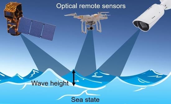
Graphical Abstract

1. Introduction

Sea states are generally considered unobtainable from a single remotely sensed optical image, whereas radar and altimetry are preferred [1]. When applied to waves, optical applications from shore-based cameras, unmanned aerial vehicles (UAVs), and satellites, derive the spatial and dynamic characteristics of waves but generally leave their energy and height aside, although these can be considered key information.
The relationship between the sea surface anomaly from still level and the pixel intensity signal is described by a modulation transfer function [2,3]. With clear blue sky, the reflected light seen by a sensor looking at the sea is not uniform and depends on the vertical view angle (or pitch) (Figure 1, see also [4]). A flat water surface reflects the sky half-dome coloring from dark at nadir to bright at the horizon. A spatio-temporal deformation of the surface, such as induced by waves, is seen as a change in location pointed in the sky dome with the specular reflection, the departure from still water conditions depending on the slope of the deformation. These optical considerations imply that: (1) short and relative steep waves dominate signal, which is consistent with the observation that short waves "clutter" optical wave measurements ([5,6]); and (2) waves propagating in the view angle direction dominate those with a perpendicular direction [7].
In the surf zone, there have been several successful attempts to use stereoscopic imaging to derive the sea surface using the wave-breaking induced foam texture for homologous points [8,9,10]. Wave heights were also derived from shore-based single cameras [11,12], using the optical signature of the wave roller and camera geometries. The consideration of the link between optical signal and the actual wave energy has generally remained outside the scope of nearshore studies using optical methods, with the exception of a few applications ([4,7,13] which were dedicated to bathymetry inversion. Several studies [14,15] underlined, using drone data, that optical signal is a proxy of the slope of the free surface and not the free surface itself, implying that one should integrate the intensity signal to get proper physical characteristics.
A recent satellite study [16] derives sea state from high-resolution optical images (Sentinel 2). In [17], a sequence of images taken from space using the Pleiades satellite shows that the optimal viewing angle is in the direction of wave propagation and that wave contrast decreases as the azimuth approaches the orientation of the wave crests. As the pitch remains almost constant, the wave signal remains visible throughout the image sequence on the orbit trajectory (changing the horizontal view angle, or azimuth), highlighting the importance of the integration of the signal within the view angle of the sensor to maintain constant wave characteristics over the orbit trajectory in a sequence. The present study is motivated by these studies that contributed to unlocking the possibility to reconstruct the sea surface anomaly; previously considered out of reach.
This paper is about how sea surface elevation anomaly (wind waves, or sea state) can be derived from optical sensors from basic and standalone optical geometry. The method is first introduced using model-derived synthetic images, then is applied to drone and satellite images. Finally, a correction for a bias of wave energy with view angle is proposed.

2. Datasets

Our methodology was tested over three datasets to allow us to test the method with a wide range of view and sensor conditions which extend and strengthen the applicability of the method.
The method was first tested against synthetic data, in a controlled environment. Free surface was first computed using the FUNWAVE wave model. Free surface was afterwards converted into intensity following the methodology described in [4]. Different view angles were tested, similarly as in [7]. The conditions were designed to mimic satellite resolution (1 m), with the free surface extracted every 0.5 s over 1-min duration for the purpose of this study. The bathymetry covered 1500 points alongshore and 1000 points cross-shore. It represents an idealized case with a rhythmic sandbar over a typical sloping beach. Random JONSWAP wave conditions are forced at the offshore boundary with Hs = 1.5 m, Tp = 10 s and Dir = 15°. This complex bathymetry leads to a complex free surface pattern [18].
The second source of data to be used in this paper was acquired at Las Cruces in Chile in November 2018. The acquisitions consist of 11 flights of an UAV equipped with an optical camera (DJI Mavic Pro) revolving around an Acoustic Doppler Current Profiler (ADCP) device deployed in reasonably deep water conditions (no breaking). Azimuth and pitch values covered a wide range of observation conditions. The acquisition was completed in less than one hour. The metadata of the images contain the location of the UAV (X,Y,Z) and the angles (roll, pitch, azimuth). This information was used to rectify the images endogenously.
The third and final data sources to be used in this paper was very high resolution satellite Pleaides (CNES/Airbus) optical imagery from the 12-frame sequence (less than 2 min) acquired in November 2017 at Capbreton, South West France to test the ability to inverse bathymetry from the derived wave information [17,18]. An ADCP was deployed in 20 m water depth by BRGM and serves as ground truth for wave height. Metadata of each image contains satellite (X,Y,Z) and rectified pixel coordinates in the real world.

3. Method

Deriving wave-induced variations of free surface from pixel intensity requires several steps: the gathering of required geometrical information; the generation of transfer function between intensity and surface slope through a regression model; and lastly the integration in polar space from surface slope to elevation within the validity range of waves.
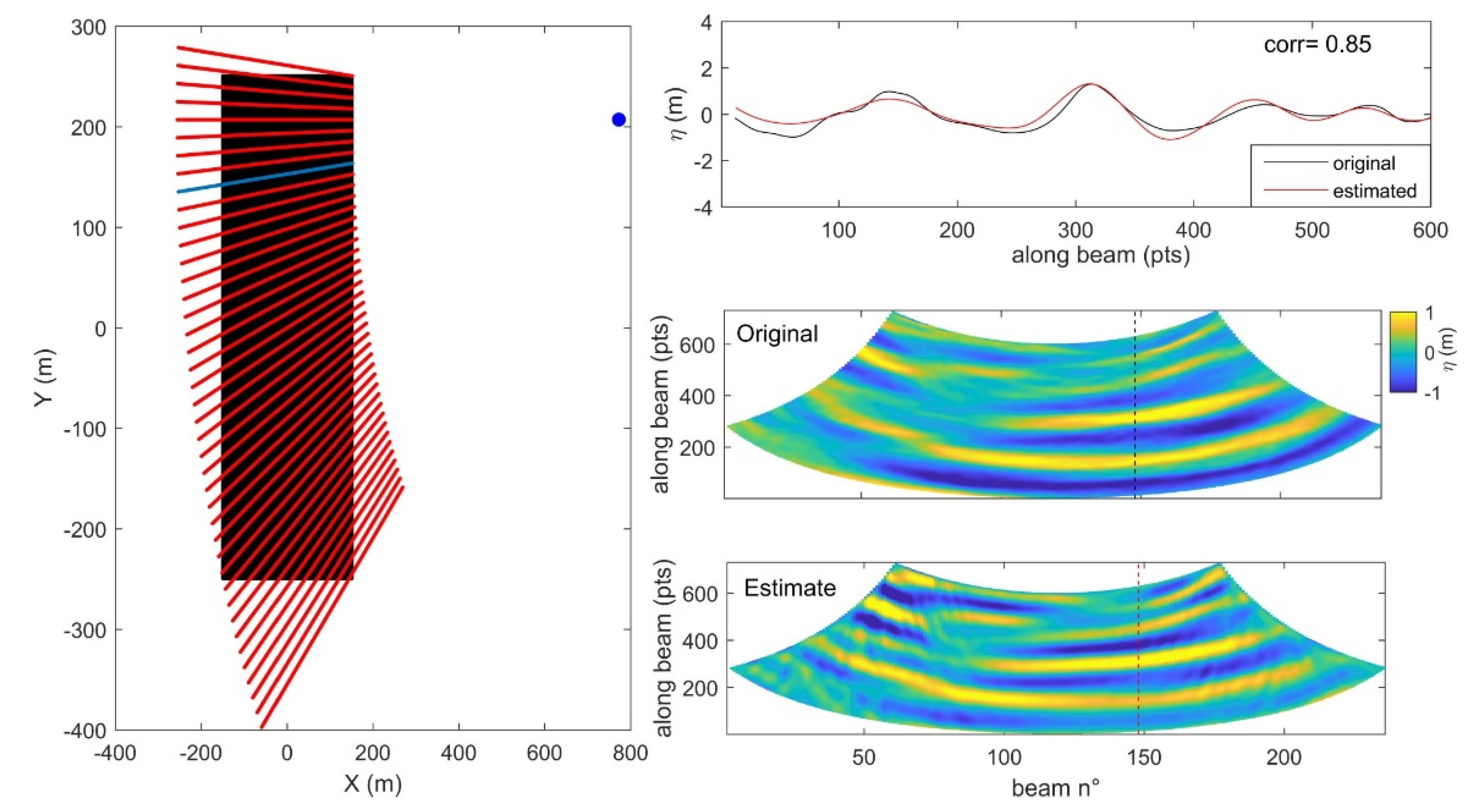
Required information are the sensor view location (x0, y0, z0) and angles, azimuth γ (horizontal) and pitch τ (vertical) (and roll but was not taken into account here as it is generally small in most of cases) or/and the location of the area of interest (X,Y), together with image intensity I. I is projected into polar coordinates with the sensor as origin. This is conducted setting beams originating from the sensor of given angular resolution ∆γ and radius resolution ∆ρ (see Figure 2).
γvec = γmin:∆γ:γmax
ρvec = ρmin:∆ρ:ρmax
I is then converted into surface slope S. To do so, most of the existing methods make assumptions on the sky dome illumination and ocean surface radiance. We aim here at feeding the transfer function from endogenous information. Here, we make use of known geometry of the still water surface, when wind waves are spatially or temporally averaged. A linear regression model is used to reconstruct this transfer function between slopestill and Istill, and coefficients are computed from:
Sstill = a + b(Istill)
The application of the model to the departure of raw I from still water Istill allows the surface slope to be estimated.
S = a + b(IIstill)
The last step is the conversion from S to elevation η. This is done by integrating S along ρ in polar beams. The optical signal is noisy by nature. As a post-processing step, the non-pertinent signal is removed by band-pass filtering the data over a given wave range (typically 2 s to 20 s, transposed to 6 m to 600 m assuming deep water dispersion L = 1.56T2).
Z γ = max
η(ρ, γ) = δρ S(ρ, γ)
γ = min η in polar space (Figure 2), can be back-projected in cartesian space for further analyses.

4. Results

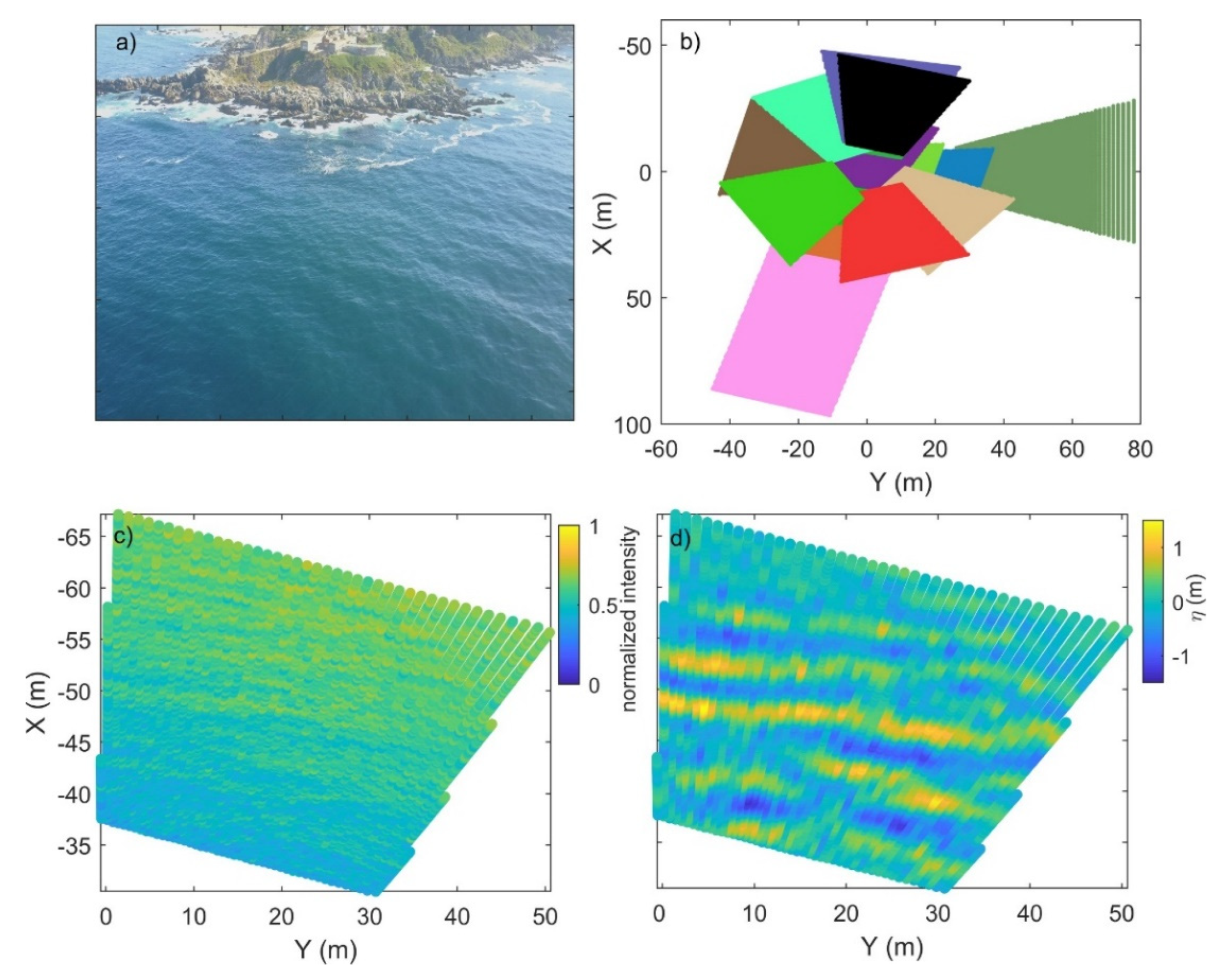
Concerning the drone images, rectification is done using endogenous drone gimbal metadata. Figure 3b shows the viewfield covered by the different acquisitions all around the ADCP mooring location. All the steps described in Section 3 are then conducted. Figure 3c shows I to build the regression model, where gradient is clearly visible.
Figure 3d shows the resulting free surface anomaly η, after estimating S, applying the model to I departure from Istill, and the integration of S along sensor view radial beams. Wave pattern is revealed in elevation.
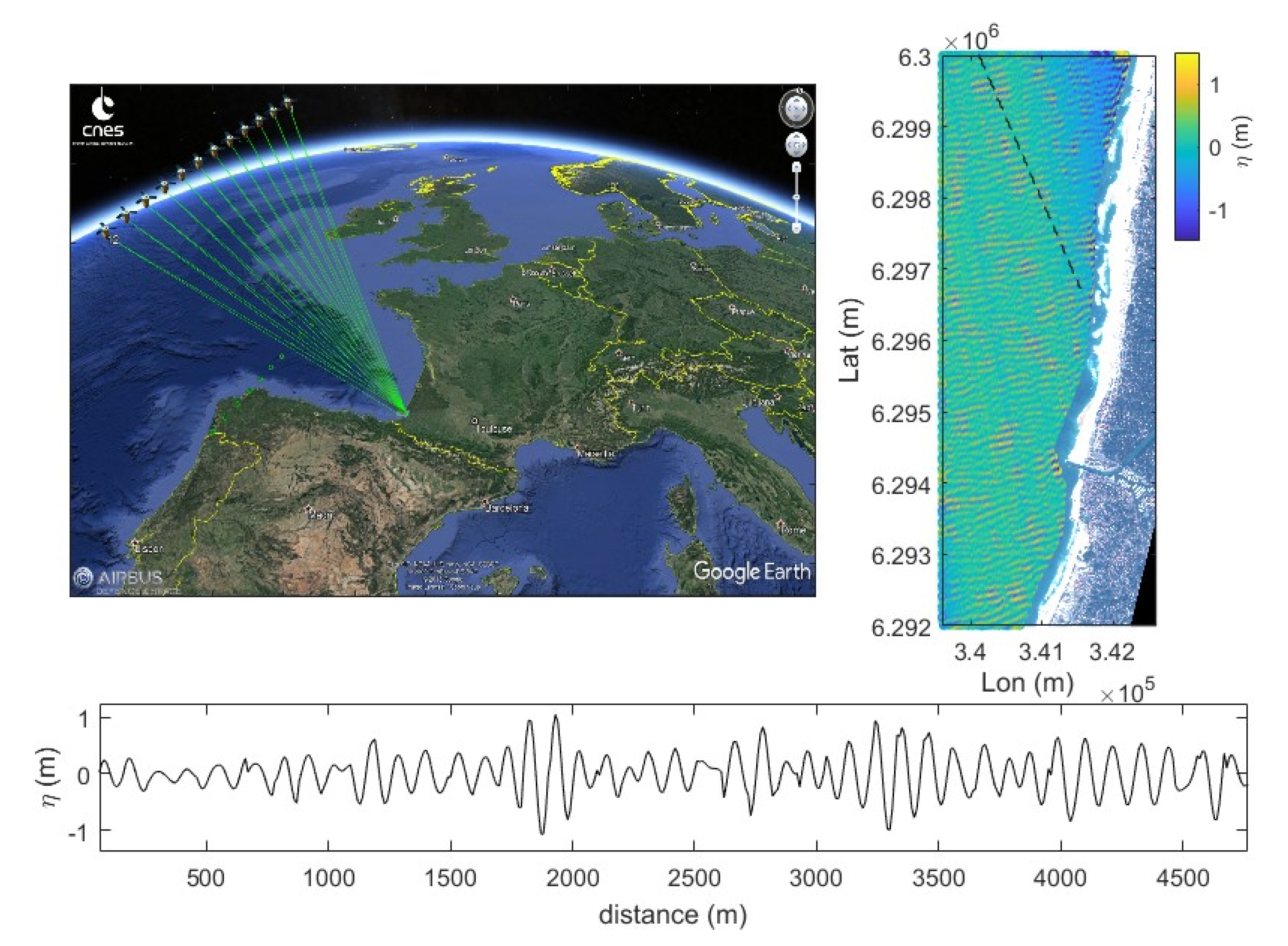
Figure 4 illustrates the free surface reconstruction from the Pleiades optical satellite at regional scale. Wave train is clearly discernible in Figure 4 and wave groups can be seen. A thorough validation of the free surface spatial field would be important for real data, similarly to what is made possible by the use of synthetic data in Figure 2. However, such as validation is currently almost impossible due to the lack of other observation tool covering such an area in an instantaneous way. To go beyond qualitative assessments, we have therefore decided, in the following paragraphs, to quantitatively compare our estimates of the bulk significant wave height (Hs) with wave gauges.
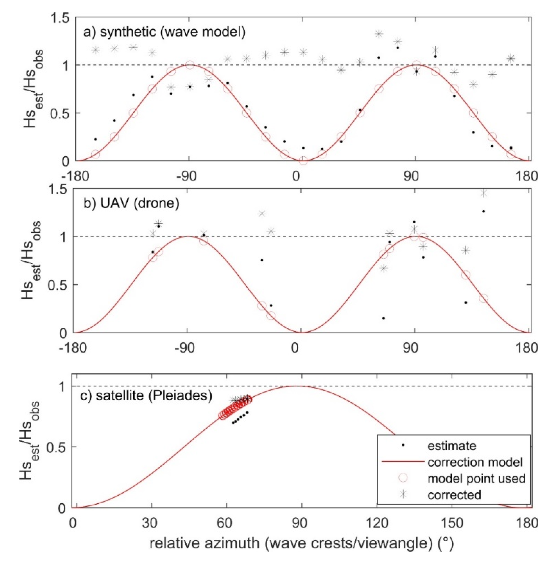
A sensitivity of the free surface reconstruction amplitude to the relative view angle is conducted here. In the synthetic wave-model controlled conditions, the sensor can virtually fly over a wide range of locations. Figure 5a shows the resulting Hs from a 360° (15° step) flight around the region of interest. The actual (model input) and retrieved free surface energy are shown. Together with lower panels, this sensitivity analysis quantifies the underestimation of energy when the view angle tends to the wave crests angle. The difference of energy is greatly correlated (0.81, significantly correlated at the 95% level) to the relative view angle to wave crests. When considering the real drone flights in Figure 5b with different view angles covering 360° (11 flights), a scatter is observed in the estimates of Hs when compared with the in-situ device. The agility of Pleiades sensor also makes it possible to observe the same scene from different view angles, although the range of view angle is narrower than with the drone flights.
Free surface at regional scale is estimated over 12 images with azimuth changing from 61 to 68° (Figure 5c). As observed in [17], wave signature and its amplitude decrease over the sequence. Similarly to the synthetic data, a bias can also be attributed to the relative view angle to waves when considering these drone and satellite applications. This underestimation effect is known (refs) and make signal perpendicular (90°) to view angle beam invisible to optical (but also others) sensors. An analytical solution exists in a form cos(α), α being the relative angle from view angle direction to wave crests (α = 0 along crest). We propose a standalone wave to do so. Dominant wave crests direction in the view field is estimated using a Radon transform [19,20], and the relative angle α is derived. When applying this correction term, RMS error is reduced by 64% in our dataset. The correction proposed here assumes that waves do not propagate strictly perpendicularly to sensor view angle. Overall, the correction of the bulk estimate of wave energy Hs seems to be the best solution.

5. Conclusions and Way Forward

We have developed a standalone regression model able to extract water free surface anomaly from single optical images. The approach uses the endogenous information contained in the background of optical observation of the water surface and geometrical considerations. This background information was used to feed a regressive model applied to determine the slope along view beams from the sensor, which was further integrated along with the latter arrays. The methodology was tested on UAV (drone) and optical very high resolution satellite, and the resulting significant wave height was compared against co-located in-situ measurements. We found that the bias is dependent on the relative azimuth view angle from the sensor to the wave crests. The resulting bulk underestimation in wave height can be mostly corrected. The linear transfer function model employed here in pitch and in the azimuth correction might be too simple to describe the non-linear wave characteristics, in particular in shallow waters where waves become skewed and asymmetric. Our method is not applicable in the surf zone where diffusive effects of foam dominate. Overall, with this stand-alone first-pass methodology, we establish the basis for deriving free surface and wave energy from a single optical imagery, which opens up a wide range of developments and applications.

Author Contributions

R.A. did the analyses and wrote the manuscript; E.W.J.B. participated to the ideas; P.A.C., R.C., L.S., F.L. conducted field experiment in Chile; A.N.L. and F.D. participated to the deployments in France; E.P. and M.L.P. revised the manuscript at different stages and collaborated on the ideas; C.C. participated to the experiment in Chile and to the ideas developed in the manuscript. All authors have read and agreed to the published version of the manuscript.

Funding

Several sources were used to achieve this work, we thank the projects FONDECYT 1170415, ANID/FONDAP/15110017 and Chile’s Marine Energy Research & Innovation Center (MERIC) CORFO project 14CEI2-28228 for the experiment in Chile, Observatoire Midi-Pyrénées (OMP) and BRGM for funding the Capbreton experiment and the Centre National d’Etudes Spatiales (CNES) for the Pleiades satellite sequence.

Data Availability Statement

Not applicable.

Acknowledgments

Any use of trade, firm, or product names is for descriptive purposes only and does not imply endorsement by the U.S. Government.

Conflicts of Interest

The authors declare no conflict of interest.

References

  1. Ardhuin, F.; Stopa, J.E.; Chapron, B.; Collard, F.; Husson, R.; Jensen, R.E.; Johannessen, J.; Mouche, A.; Passaro, M.; Quartly, G.D.; et al. Observing Sea States. Front. Mar. Sci. 2019, 6, 124. [Google Scholar] [CrossRef] [Green Version]
  2. Holman, R.; Brodie, K.; Spore, N. Surf zone characterization using a small quadcopter: Technical issues and procedures. IEEE Trans. Geosci. Rem. Sens. 2017, 55, 2017–2027. [Google Scholar] [CrossRef]
  3. Brodie, K.; Palmsten, M.; Hesser, T.; Dickhudt, P.; Raubenheimer, B.; Ladner, H.; Elgar, S. Evaluation of video-based linear depth inversion performance and applications using altimeters and hydrographic surveys in a wide range of environmental conditions. Appl. Opt. 2018, 136, 147–160. [Google Scholar] [CrossRef] [Green Version]
  4. Chickadel, C. Remote Measurements of Waves and Currents over Complex Bathymetry. Ph.D. Thesis, Oregon State University, Corvallis, OR, USA, 2007. [Google Scholar]
  5. Chapman, R.; Irani, G. Errors in estimating slope spectra from wave images. Appl. Opt. 1994, 20, 3645–3652. [Google Scholar] [CrossRef] [PubMed]
  6. Jaihne, B.; Klinke, J.; Waas, S. Imaging of short ocean wind waves: A critical theoretical 186 review. Opt. Soc. Am. A 1994, 11, 2197–2209. [Google Scholar] [CrossRef]
  7. Perugini, E.; Soldini, L.; Palmsten, M.L.; Calantoni, J.; Brocchini, M. Linear depth inversion 188 sensitivity to wave viewing angle using synthetic optical video. Coast. Eng. 2019, 152, 103535. [Google Scholar] [CrossRef]
  8. Bechle, A.J.; Wu, C.H. Virtual wave gauges based upon stereo imaging for measuring surface wave characteristics. Coast. Eng. 2011, 58, 305–316. [Google Scholar] [CrossRef]
  9. Buscombe, D.; Carini, R.J.; Harrison, S.R.; Chickadel, C.C.; Warrick, J.A. Optical wave gauging using deep neural networks. Coast. Eng. 2020, 155, 103593. [Google Scholar] [CrossRef]
  10. De Vries, S.; Hill, D.; de Schipper, M.; Stive, M. Using stereo photogrammetry to measure coastal waves. J. Coast. Res. 2009, SI 56, 1484–1488. [Google Scholar]
  11. Almar, R.; Cienfuegos, R.; Catalán, P.; Michallet, H.; Castelle, B.; Bonneton, P.; Marieu, V.A. new breaking wave height direct estimator from video imagery. Coast. Eng. 2012, 61, 42–48. [Google Scholar] [CrossRef]
  12. Andriolo, U.; Mendes, D.; Taborda, R. Breaking Wave Height Estimation from Time Images: Two Methods for Coastal Video Monitoring Systems. Remote Sens. 2020, 12, 204. [Google Scholar] [CrossRef] [Green Version]
  13. Holman, R.; Plant, N.; Holland, T. cBathy: A robust algorithm for estimating nearshore bathymetry. J. Geophys. Res. Ocean. 2013, 118, 2595–2609. [Google Scholar] [CrossRef]
  14. Bergsma, E.W.J.; Almar, R.; de Almeida, L.P.M.; Sall, M. On the Operational Use of UAVs for Video-Derived Bathymetry. Coast. Eng. 2019, 152, 103527. [Google Scholar] [CrossRef]
  15. Thuan, D.H.; Almar, R.; Marchesiello, P.; Viet, N.T. Video Sensing of Nearshore Bathymetry Evolution with Error Estimate. Remote Sens. 2019, 7, 233. [Google Scholar] [CrossRef] [Green Version]
  16. Kudryavtsev, V.; Yurovskaya, M.; Chapron, B.; Collard, F.; Donlon, C. Sun glitter imagery of ocean surface waves. Part 1: Directional spectrum retrieval and validation. J. Geophys. Res. Ocean. 2017, 122, 1369–1383. [Google Scholar] [CrossRef] [Green Version]
  17. Almar, R.; Bergsma, E.; Maisongrande, P.; Melo de Almeida, L. Coastal bathymetry from 214 optical submetric satellite video sequence: A showcase with Pleiades persistent mode. Remote Sens. Environ. 2019, 231, 111263. [Google Scholar] [CrossRef]
  18. Almar, R.; Bergsma, E.W.; Gawehn, M.; Aarninkhof, S.; Benshila, R. High-frequency Tem-poral Wave-pattern Reconstruction from a Few Satellite Images: A New Method towards Estimating Regional Bathymetry. J. Coast. Res. 2020, 95, 996–1000. [Google Scholar] [CrossRef]
  19. Almar, R.; Michallet, H.; Cienfuegos, R.; Bonneton, P.; Tissier, M.; Ruessink, G. On the use of the Radon Transform in studying nearshore wave dynamics. Coast. Eng. 2014, 92, 24–30. [Google Scholar] [CrossRef]
  20. Bergsma, E.W.J.; Almar, R.; Maisongrande, P. Radon-Augmented Sentinel-2 Satellite Imagery to Derive Wave-Patterns and Regional Bathymetry. Remote Sens. 2019, 11, 1918. [Google Scholar] [CrossRef] [Green Version]
Figure 1. (a) Illustration of the sky half-dome coloring from dark at nadir to bright at the horizon along the view angle cross-section, (b) how the specular reflection on the ocean surface looks like and how wave appear, and (c) when looking down with avoiding specular reflection and favoring penetration. (d) Sketch of the method principle.
Remotesensing 13 00679 g001
Figure 2. Synthetic wave-model and radiance model data. (a) Illustration of system change from cartesian (black) to polar coordinates (red) centered on the sensor (blue filled circle). (b) free surface along the blue transect in (a,c,d) are signal reconstruction in sensor view for original and estimated data respectively. The number of beams and beam length depend on polar resolution.
Remotesensing 13 00679 g002
Figure 3. (a) A view of the study site for the drone (UAV) case, off the coast in deep water, Las Cruces, Chile. (b) View fields for the flights in Cartesian coordinates. (c) Raw normalized image intensity, and (d) the resulting free surface anomaly showing waves. (c,d) correspond to black flight in (b).
Remotesensing 13 00679 g003
Figure 4. Reconstruction from the Pleiades satellite from image number 5 in the 11 images sequence. The upper left panel shows the satellite trajectory and region of interest, the upper right panel shows the reconstructed free surface superimposed with true color Pleiades image, where the wave train is clearly discernible, and the lower panel shows free surface along the transect showed above. Wave groups can be seen.
Remotesensing 13 00679 g004
Figure 5. Sensitivity of the wave energy estimation to the relative view angle to wave crest for (a) the synthetic dataset (wave model), (b) UAV (drone) flights and (c) satellite (Pleiades) sequence. Significant wave height Hsest is computed from spatial variance of free surface, while Hsobs is computed from in-situ sensors for real data cases or from variance of free surface for the model case.
Remotesensing 13 00679 g005
Publisher’s Note: MDPI stays neutral with regard to jurisdictional claims in published maps and institutional affiliations.