Article

Volumetric Analysis of the Landslide in Abe Barek, Afghanistan Based on Nonlinear Mapping of Stereo Satellite Imagery-Derived DEMs

by
Mujeeb Rahman Atefi
1,2,* and
Hiroyuki Miura
3
1
Department of Architecture, Hiroshima University, Kagamiyama 1-4-1, Higashi-Hiroshima, Hiroshima 739-8527, Japan
2
Faculty of Engineering, Balkh University, Mazar-i-Sharif 1701, Balkh, Afghanistan
3
Department of Advanced Science and Engineering, Hiroshima University, Kagamiyama 1-4-1, Higashi-Hiroshima, Hiroshima 739-8527, Japan
*
Author to whom correspondence should be addressed.
Remote Sens. 2021, 13(3), 446; https://doi.org/10.3390/rs13030446
Submission received: 16 December 2020 / Revised: 23 January 2021 / Accepted: 24 January 2021 / Published: 27 January 2021

Abstract

:
On 2 May 2014, a large-scale landslide in Abe Barek, Badakhshan, Afghanistan, produced extensive damage to the buildings and killed hundreds of people. Evaluations of the extent and the volume of the displaced materials are vital for post-disaster management activities. In this study, we present the applicability of a nonlinear geometric correction technique for decreasing the undesired registration errors between pre- and post-event digital elevation models (DEMs) generated from high-resolution stereo pair satellite imagery, identifying landslide affected areas, and quantifying the landslide volume from DEMs of difference (DoD) analysis. The nonlinear mapping method consists of shifting vector generation in subareas of the DEMs, consensus operations, and interpolation of the shifting vectors. The quality assessment confirmed that the method outperformed the simple DoD technique by eliminating a large-scale of geometric errors in an unaffected area. We estimated the volume of the landslide as 1.05 × 10⁶ m3 from the DoD corrected by the nonlinear method, and discussed the relationship between the area and volume compared to those of the previous studies.

Graphical Abstract

1. Introduction

Landslides induced by heavy rainfalls and earthquakes are among the most common geohazard phenomena that frequently occur in mountainous regions, which constitute one of the major hazards responsible for the interruption and severe destruction of transport-related structures, industrial and hydropower plants, as well as cause the loss of lives worldwide. Recent studies show that the number of locations, activities, severities, frequencies of landslides, and the social and economic impacts increase with time in many regions [1,2,3,4].
With mountains dominating the landscapes, Afghanistan is considered a country prone to several geomorphological hazards such as earthquakes, landslides, flooding, drought, avalanches, and man-made disasters. Safety and economic problems made Afghanistan among the countries with only a few researches on landslides. Therefore, the exact location and number of landslides prone areas have not been specified across the country yet, but as per records of the United Nations Office for the Coordination of Humanitarian Affairs [5], of all-natural disasters reported in Afghanistan between 2012 and 2020, landslides constitute 6.8% of total natural hazard incidents which account for 30.3% of all geohazards related deaths. Of all the recorded landslides in the country between 2012 to 2020 [5], 41.8% occurred in Badakhshan Province. Surprisingly, Badakhshan’s landslide events comprise 16.3% of all the country’s natural disaster incidents, which account for 53.6% of all the recorded landslide related deaths in Afghanistan. As reported by [6], Badakhshan province is a high priority province due to its greater susceptibility to the landslide.
Badakhshan province’s high susceptibility to landslides led us to study one of the landslides’ affected areas using remote sensing. The attention spotlight is on the Abe Barek landslide incident, which occurred on 2 May 2014, in Badakhshan, Afghanistan. It brought great international attention due to its large dimensions and catastrophic damage. In accordance with the United Nations Institute for Training and Research [7,8], the number of death tolls ranged from 300 to more than 2700. Based on an initial comparison of high-resolution WorldView-2 satellite imagery of the pre-and post-event, a total of 87 structures were buried by the mass of soil [7]. Moreover, after investigating and comparing different areal images, they concluded that the previous mass movements occurred and were highly likely to happen again in the same area [7,8]. Zhang et al. [8] conducted landslide susceptibility assessments in the Abe Barek landslide affected area using a low-resolution of 90 m SRTM elevation data and digital elevation model (DEM) derivatives with a significant limitation of lacking landslide inventory data. Aside from [8], there has not been any other research to investigate the Abe Barek landslide area. Therefore, the volume of the landslide has remained unknown to date.
Estimating the volume of displaced materials in a landslide is a crucial index for understanding the significance of the event and planning post-disaster activities. A difference of elevation between pre-and post-event DEMs (DEMs of difference: DoD) has been used to identify the location of the affected areas and quantify the displaced soil volume [9,10,11,12]. Among various remote sensing data sources, the light detection and ranging (LiDAR) technique can produce a reliable estimate of morphological change [13]. However, LiDAR observations have been rarely conducted in remote areas such as the Abe Barek area. The satellite image-based approach is more feasible to assess the natural disasters in such remote areas. DEM can be created from a stereo analysis of multiple satellite images with different off-nadir angles. In the case that a set of high-resolution stereo pair satellite images is available before and after the disaster, the DoD analysis can be performed by developing pre-and post-event DEMs.
In order to quantify landslide volumes from DoD, the geometries of the obtained DEMs need to be registered accurately. However, the DEMs errors of height values are found in many cases, even when the data is geometrically registered. Previous studies revealed that the uncertainty, including registration-noise or locational errors in multi-temporal DEMs, would cause the miscalculation of soil volumes [14,15]. These errors arise from many factors such as the quality of original data, interpolation algorithm, projection method during the DEM creation process, etc. [16]. The horizontal misregistration between DEMs would be one of the major causes of the uncertainty in the DoD analysis.
Various researches have given special attention to the development of advanced registration techniques not only for aerial images [17,18,19] but also for multi-temporal DEMs [14,20,21]. Jaboyedoff et al. [13] addressed the use of ground control points (GCPs) to refine the generic sensor’s orientations. The collection of GCPs is time-consuming in an urgent time of disaster. Chen et al. [14] proposed a mass balance model to accurately correct two DEMs and quantify the landslide’s accumulated volume. However, the mass balance calculation would be difficult in affected areas where collapsed soils flowed into buildings and the downstream rivers. Hirakawa [20] also proposed an optimization-based method to automatically correct the geometrical errors in multi-temporal LiDAR-derived DEMs by assuming unique linear errors throughout the area of concern. It would be difficult to correct the geometries of the DEMs when substantial nonlinear distortions are found in the area of interest. Those previous studies indicate that misregistration caused by nonlinear distortions in multi-temporal DEMs still remains an open problem. Miura [21] presented a nonlinear mapping technique for reducing horizontal locational errors between LiDAR-derived DEMs and estimating the displaced volumes of debris flows. However, the applicability of the technique for a landslide in satellite image-derived DEMs, and the parameter selections in the technique were not fully discussed in the previous study [21].
In this paper, we followed the proposed methodology [21] to present the nonlinear mapping technique’s applicability in reducing the registration-noise of the multi-temporal DEMs to estimate the volume of the Abe Barek landslide. We analyzed a set of high-resolution DEMs generated from stereo pair satellite images. The nonlinear mapping technique was applied for reducing the nonlinear distortions in the DEMs. Unlike the previous work [21], here in this study, particular attention was given to illustrate the efficacy of the method using both statistical approaches and profile cross-sections. The volume of the landslide was estimated from the DoD corrected by the nonlinear technique. The aspects of this study are summarized as the following:
  • Applicability of nonlinear mapping technique on minimizing geometric errors.
  • Validation of nonlinear mapping technique by the comparison of several descriptive and graphical parameters.
  • Landslide detection and volume estimation by using the corrected DoD.
  • Validation and comparison of the obtained volume of the displaced material with previous studies.

2. The Landslide in Abe Barek, Afghanistan

On 2 May 2014, a very large-scale landslide occurred in Abe Barek (Figure 1), Argo District, Badakhshan Province, Afghanistan. It was the worst landslide in 2014, killing 300 to more than 2700 people [8]. According to the locals, two landslides occurred within a concise space of time. The villagers may lack the specialized knowledge, training, and necessary equipment to perform triage and started the search and rescue operations for assistance to the first trapped victims shortly after the first incident [22]. Tragically, many volunteer rescuers become secondary victims themselves [23]. Considering the remoteness of the landslide area, rough road conditions, insufficient capacity for fast and well-timed transfer of machinery, and the necessary equipment, the government quickly concluded that retrieving the buried bodies is unattainable. Hence, the site was declared a mass grave [24]. Figure 2a, taken in [25] and outlined with a yellow color, shows the landslide’s downward movement direction in a sufficiently inclined surface rupture over a considerable distance and buried the settlements along its pathway. Moreover, Figure 2a,b clearly illustrates previous landslides’ boundaries in the same position with red lines.
The study area with a latitude of 37°1′ 18″ N and a longitude of 70°22′01″ E is situated 21 km away from Faizabad, the capital of Badakhshan province. Badakhshan is one of the 34 provinces of Afghanistan, located in the northeastern part of the country along the Pamir and Hindu Kush Mountains. Some of its mountains lay between 3000–7000 m above sea level and are covered with snow and glaciers throughout the year. Badakhshan is one of the most remote, least developed, and disaster-prone regions, which borders Tajikistan to the north, Pakistan to the south, and China to the easternmost (Figure 1a). The presence of two active plate boundaries [26], namely “North Afghan Platform and Transgressional Plate boundary”, and the passing of three major active faults through the province [27], namely the Central Badakhshan Fault, Darvaz Fault, and Henjvan Fault, making it the highest seismic prone region in the country and is arguably one the most vulnerable regions to all kinds of natural disasters. With this regard, most of the researchers relate the majority of the landslide hazards to earthquakes. Argo district (Figure 1c), of which Abe Barek is one of its villages, with 10% of the whole province population, is the most populous district in Badakhshan [28]. According to the previous study [8], 30.2% of the entire land in Badakhshan province is covered by a slope gradient of 20–30°, and in the area where the landslide occurred, 78% of its land is made up of a slope gradient of 20 to 40°. This might be considered as one of the reasons why this area is prone to landslides. The Abe Barek landslide area brutally buried houses and killed large numbers of people, which can be categorized as the most life-threatening [8] natural disasters after two incidents of the 1998 earthquakes [27,29] occurred in this area. To date, Shroder [30,31] has determined 34 large loess landslides that are commonly triggered by saturation and liquefaction in this area.
Knowing the cause of the landslides is extremely important. However, as mentioned, not so many studies have been conducted in the area of interest to figure out the main reason. The only research conducted in the study area is the susceptibility assessment in the Abe Barek [8]. Landslide factors such as topography, climate (rain), geology and seismicity of the area, land cover and land use, and previous earthquakes were reviewed deeply. Eventually, they identified the following factors as a leading cause of the incident:
  • Weakening of the rock-based silt-covered area due to the repeated seismic events.
  • Slope instability further intensifies due to the remaining too loose materials from the previous landslides at the same position.
  • Slope instability due to the increased infiltration of rainwater into the loose soil.
  • The presence of sensitive material which is very prone to landslides.
  • Increasing the soil water content from the rapid melting of deep snow and spring rains up to 200 mm.
  • Land use and irrigation activities.
Finally, it can be concluded that the cause of the landslide is not one. Rather, a set of triggering factors (e.g., complex geology, the presence of landslide-prone material [30,31], previous earthquake records, and close distance to the fault line’s intersection [29], summer rains, and melting snow) or a combination of any of such mentioned factors possibly lead to this unfortunate situation.

3. Material

In this study, stereo pair high-resolution satellite images were gathered to generate pre-and post-event DEMs. The pan-sharpened GeoEye-1 images with the spatial resolution of 0.5 m observed in June 2012 were analyzed to create the pre-event DEM. The panchromatic IKONOS-2 images with the spatial resolution of 0.8 m observed 2 months after the event in 2014 were analyzed to create the post-event DEM. Table 1 shows the characteristics of the satellite images used in this study and their observation conditions. Since the pre-event images were observed on the same day with different off-nadir angles, the pair images’ quality can be judged as very good. On the other hand, since the time interval of the observations of the post-event images is 8 days, and land cover changes were slightly observed between the images, we judged the pair quality of the post-event images as good.
Figure 3 shows the flowchart for the DEM generations from the acquired satellite images. The DEMs and orthorectified images were generated by a dense stereo matching technique using a commercial software (Agisoft Metashape Professional Ver. 1.6.3) [32]. The technique consists of a photo alignment, generation of the three-dimensional dense point cloud, and building of the mesh. Approximately 168 thousand tie points and 34 million-point clouds were extracted in the pair of the pre-event images, indicating that the mean cloud density is 1.4 points per square meter. On the other hand, approximately five thousand tie points and 16 million-point clouds were extracted in the pair of the post-event images, demonstrating that the mean cloud density is 0.5 points per square meter. The images’ geographic locations were coordinated using rational polynomial coefficient (RPC) files. The RPC files were provided by the supplier as a standard positioning assistance dataset, including polynomial equations to relate geographic locations (latitude, longitude, and height) with locations in the image (row and column).
Figure 4a,b illustrates the pre- and post-event DEMs created from the images, respectively and Figure 4c,d shows the hillshade effects on the DEMs. Unexpected small concavities and convexities were found in the post-event DEMs (Figure 4d), probably due to the lower density of the point clouds. Figure 4e,f shows the pre- and post-event orthorectified images, respectively. Figure 4g,h illustrates the close-up of the generated point clouds in a rectangular area shown in Figure 4e,f. From the close-up image, the concentration of the cloud points in the pre-event DEM is substantially higher than that of the post-event DEM. The pre-event data spatial resolutions were 1.0 m, whereas the post-event data spatial resolutions were 1.5 m due to the different spatial resolutions of the original images. Since the spatial resolution and the pair quality of the pre-event data are higher, the post-event DEM and orthorectified image were resampled to a 1.0 m resolution by the cubic convolution technique for the following change detection operation in order to obtain a detailed morphological change.
The derived DEMs were georeferenced in GIS during the stereo matching operations based on the RPC files. Then, they were applied to the DoD technique by subtracting the pre-event image from the post-event image. The DoD (post-pre) obtained from the pixel-based change detection is shown in Figure 5. Although the DEMs were geometrically corrected by the RPC files, significant noises or errors in height values were found even in unaffected areas. These false detections would probably arise from the locational errors (e.g., horizontal errors) in the DEMs, indicating that two DEM images were not perfectly matched. Therefore, a further geometric correction would be necessary to accurately enhance the DEM’s matching and accurately extract the geomorphological change. Here, in this study, a nonlinear mapping technique would be utilized to diminish the DEM’s locational errors generated in DoD.

4. Methodology

The nonlinear mapping method was briefly introduced in the previous work [21]. Section 4.1 explains the method in detail, the experiments for selecting the parameters are presented in Section 4.2, and the quality assessment by the selected parameters are discussed in Section 4.3.

4.1. Nonlinear Mapping Method

An adaptive nonlinear mapping method was introduced by Kosugi et al. [33] and Nakamura et al. [34] to superpose a pair of aerial or satellite images accurately and detect pixel-by-pixel changes automatically. The method can geometrically correct the images even if rotational gaps and local skews are obtained in the images. The method was applied not only to aerial images but also to LiDAR-derived DEMs by one of the authors for quantifying volumes of debris flows [21]. Hence, we applied this technique to the obtained DEMs in this study.
The flowchart of the nonlinear mapping technique for pre-and post-event DEMs is presented in Figure 6. This method consists of four operations: Shifting vector generation in subareas, consensus operations for shifting vectors, interpolation of consented shifting vectors, and the repetition of three previous operations until a satisfactory outcome has been achieved. In this analysis, the pre-and post-event DEMs are defined as the controller (reference) data and follower data, respectively. First, both DEMs are divided into subareas with the window size of NW-by-NW pixels (Figure 7). The segmented subarea (NW × NW pixels) in the follower data looks for the best-matched segment in the given segment’s neighborhood (NS pixels for left, right, upward, and downward) in the corresponding controller data by adopting the smallest elevations’ difference using the following formula:
s ( i c , j c ) = 1 N W 2 j = ( N W 1 ) / 2 ( N W 1 ) / 2   i = ( N W 1 ) / 2 ( N W 1 ) / 2 { d 1 ( i c + i , j c + j ) d 2 ( i c + i + d x , j c + j + d y ) } 2
The elevations’ difference (s-value) is calculated in each subarea. Here, d1 and d2 are the elevations in the pre-and post-event DEMs, respectively, and ic and jc indicate the subarea’s central location in x- and y-directions, respectively. The shifting vectors are determined from dx and dy in pixels when the minimum s-value is obtained within the given search area in NW-by-NW pixels. It would be difficult to search for the appropriate shifting vectors in landslide-affected areas due to the fact that the ground movement significantly changes the topography after the event. Since the false shifting vectors would be generated in such changed areas, the shifting vectors need to be corrected considering the vectors in the altered areas’ vicinities.
The consensus operation will be performed to correct the overestimated shifting vectors or false generated shifting vectors. The first scalars of the shifting vectors are calculated using Equation (2) in all the subareas.
d = d x 2 + d y 2
Figure 8a shows the schematic diagram for the histogram of the vectors and threshold selection to two classes. The threshold value of the vectors (dth) is determined by maximizing the ratio of inter-class variance ( σ B ) to the total variance ( σ T ) calculated Equations (3) to (5) [34,35].
d t h = d   s . t .   m a x d ( σ B 2 ( d ) σ T 2 ( d ) )
σ B 2 = n 1 ( m 1 m 0 ) 2 + n 2 ( m 2 m 0 ) 2 m 1 + m 2
σ T 2 = σ 1 2 + σ 2 2
Here, m0, m1, and m2 indicate the mean value of d for all the vectors, the mean value in class 1, and the mean value in class 2, respectively. Additionally, n1 and n2 are the number of vectors in classes 1 and 2, respectively. In a similar manner, σ 1 and σ 2 represent the variances of the vectors in classes 1 and 2, respectively. When the d-value in a subarea is larger than dth, the vectors are classified to class 2. In that case, the shifting vectors are corrected by giving median values of dx and dy obtained within the neighborhood subareas (NC-by-NC subareas), as shown in Figure 8. The shifting vectors are provided to all the pixels from the subareas’ vectors by the bilinear interpolation technique. These operations are repeated by the given number of iteration (n). Finally, the controller data is geometrically corrected based on the shifting vector in each pixel. Figure 9 illustrates the comparison of the schematic plan and profile before and after the nonlinear mapping-based geometric correction. Four parameters, NW, NS, NC, and n, are required to perform the nonlinear mapping technique.

4.2. Evaluation and Applicability of the Method

We applied the nonlinear mapping method to the pre-and post-event DEMs. For that, the algorithm needs a combination of entry parameters. These key input parameters are NW (window size or size of subarea), NS (search area), NC (consensus area), n (number of iterations). The selection of the parameters in the method was discussed in a selected testing zone with different combination values of these parameters. In this study, a set of scenarios were examined with different values of NW, NS, NC, and n. In the following subsections, we performed statistical and shifting vector assessments. Based on the quality assessment result, the best possible combination of parameters (NW, NS, NC, and n) was selected.

4.2.1. Statistical Assessment

As shown by the dotted rectangle in Figure 10, the nonlinear mapping technique was applied repeatedly with different scenarios for the selected test area. For instance, in every process of the analysis, the pre-event DEM subareas were given a different search area (pixel value) and consensus value to automatically search and match with the best possible corresponding reference point in the post-event DEM. Typical parameters illustrated in Table 2 were selected for the accuracy assessment. It is convenient to use descriptive statistics (mean and standard deviation) to evaluate different categories and identify the differences among other scenarios. If the geometric correction is successfully performed to the data, the DoDs mean value would be zero or close to zero in the unaffected areas. As shown in Table 2, different window sizes (e.g., NW = 5,7,9…31) and search areas of NS × NS (3 × 3, 5 × 5, 7 × 7…31 × 31) pixels are evaluated through a repetitive iteration procedure. Finally, in this study, the window size (NW = 5 pixels) and search area (NS = 9 × 9) highlighted in Table 2 with bold text were chosen based on the lowest mean and standard deviations of DoD maps.

4.2.2. Shifting Vectors Assessment

Figure 11a–i illustrate the generated shifting vectors for the scenario numbers 2–10 of Table 2. The selected test area of the pre-event DEM based on the entry-parameters described above looked for the best matching segment in the vicinity of the corresponding reference point in the chosen test area of the post-event DEM. As shown in Figure 11, shifting vectors were generated if the best matching point is not the same as the reference point. During the operation analysis, more than nine profiles of shifting vectors have been generated. Here, in Figure 11, nine of them have been shown. A moderate vector movement that brings reasonable smoothness in the DEMs quality and considerably removes the locational errors in the unaffected area compared to another set of shifting vectors would be chosen from all the generated shifting vectors. After the comparison, in Figure 11, we selected the shifting vector with label c. which corresponds to the parametric combination (NW = 5, NS = 9, NC = 3, n = 3). Since the shifting of the vectors in the selected parameters is smaller than the other shifting vectors (e.g., scenario number five to ten in Table 2 shown by Figure 11d–i), the corrected DEM eliminated the locational errors in the unaffected area significantly compared to the other shifting vector-related DEMs. Moreover, the selected shifting vector had the smallest mean, deviation, and sum of squares, as discussed and shown in Table 2.

4.3. Quality Assessment
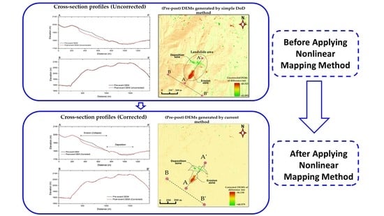
The histogram is a very handy way of graphically displaying the information contained in a single band of remotely sensed images [36]. In remote sensing, scientists usually examine histograms for each band to determine the quality of satellite images. The histogram presents the information by which one can figure out the quality of image data. In most cases, scientists show the before and after histogram graphs to compare the effectiveness of their image enhancement methods [37]. Hence, we compared the distribution of the difference of elevations in the corrected DEM with the uncorrected DEM using histograms.
As shown in Figure 12, the uncorrected DoDs histogram (red line) generated a negatively skewed distribution shape histogram indicating the poor quality of the data or the presence of additional noise in data. However, the corrected DEM histogram (blue line) produces a symmetrical frequency distribution. The values are distributed around a central value, and the pixel numbers decline away from this central point. The distribution graph completely changed to a bell-shaped and is called a normal distribution. It can be concluded that the data quality in DoD after applying the nonlinear mapping method dramatically increased. Meanwhile, the incorrectly detected errors have drastically decreased after conducting the nonlinear mapping method and choosing the parametric combination.

5. Results

In this chapter, we evaluated the profile cross-sections using the corrected DEMs, including the landslide area to validate the nonlinear mapping method in Section 5.1, and presented the estimation of the soil volume through a comparison of the volume estimated from the uncorrected DEMs in Section 5.2.

5.1. Comparison of Cross-Sections of DEMs in the Affected and Unaffected Mountain Areas

We compared the profile cross-sections between the corrected DEMs and uncorrected DEMs to confirm the nonlinear technique’s quality. Figure 13a shows the DoD obtained from the uncorrected DEM. We selected two cross-section lines in the affected and unaffected areas, as illustrated by the A-A’ and B-B’ lines in Figure 13b,c, respectively. It was observed from the profile cross-sections that significant gaps between the pre-and post-event elevations are prominent throughout the cross-sections in the uncorrected DEMs. Figure 14a illustrates the DoD obtained from the corrected DEMs in this study, and the cross-sections in the A-A’ and B-B’ lines are shown in Figure 14b,c, respectively. We confirmed that the locational errors (e.g., horizontal gaps) were significantly decreased, and the post-event line matches very well with the pre-event topographies.
We also evaluated the model performance in decreasing the locational errors using the quantitative value of the root means square error (RMSE) to confirm the degree of the matching in both corrected and uncorrected data in the unaffected area (Figure 13c and Figure 14c). This indicator has been frequently used to evaluate the prediction error quantitatively [38]. The RMSE of the corrected profile cross-section was obtained at 0.81 m, whereas the RMSE for the uncorrected profile cross-section was obtained at 3.81 m, which is more than four times larger than that of the corrected one. It suggests that the horizontal locational errors are the leading cause of the change detection errors not only in the unaffected areas but also in the affected areas. The employed geometric correction model of the current study can be utilized for accurately extracting the geomorphological changes.

5.2. Volume Estimation

Before quantifying the volume of the displaced soil, the boundary line of erosion and deposition areas of the landslide need to be delineated. Figure 15a shows the DoD map (post-pre) obtained from the corrected DEMs with the landslide area delineated by the combination of the satellite images, the ground photos shown in Figure 2, and the cross-sections shown in Figure 15b. The colors in the DoD map in Figure 15a illustrate the distribution of displaced soil depths in the Abe Barek landslide disaster area. The DoD map consists of positive and negative pixel values. The negative values indicate soil erosion, which is filled in red to orange color pixels, and the pixel values range from (−37 m < DoD < 0 m). On the other hand, the positive pixel values correspond to the deposition of the displaced soil as shown in the blue to green pixel colors, and the pixel values vary from (0 m < DoD < +41 m).
Referring to the cross-sections drawn in Figure 15b, the landslide moved in a complicated fashion in the erosion-affected sections. The post-event elevations were significantly decreased in the southern areas such as lines C-C’, D-D’, E-E’, F-F’, and G-G’, whereas the elevations were increased after the landslide in the northern areas such as lines I-I’, J-J’, and K-K’, as shown in Figure 15b. Judging from the cross-sections in Figure 15b, we can claim that in the upper slope section line C-C’ to the line G-G’ the erosion occurred, in which the eroded mass of the material is thought to move as a rigid block with a significant depth. By contrast, from the cross-section H-H’ onward, which is the ending boundary of the erosion-affected area, the displaced material′s movements became more complicated. In other words, the mass of the material that was moving almost in a rigid block turned into many sub-slide surfaces at the lower reach of G-G’, and each block in a separated fashion, choosing its direction to reach a remarkable distance.
From section I-I’ onward, the post-event elevation increases as the movement continues with a distance towards the northern direction. It means that the landslide started depositing from I-I’ on to the stopping points in the deposition zone. Finally, the landslide material that accumulated along the purple boundary polygon filled with a green color in Figure 15a caused the severe building damage. The redline polygon and dotted purple line polygon in Figure 15a shows the erosion area (upstream) and the deposition area (downstream) of the displaced materials, respectively.
The volume of the displaced material was estimated using the corrected DoD map by aggregating the positive and negative pixel values separately in their boundaries and multiplying them to the corresponding area boundaries. As an example, in Figure 16, we present the elevation change along the cross-section line A-A’. It indicates the elevation difference between the pre- and post-event DEMs along the mentioned cross-section line shown in Figure 15. The positive values indicate the deposition of the material, whereas negative values indicate erosion of the materials. The maximum erosion depth along the cross-section line was obtained at 37.7 m, while on the contrary, the maximum deposition depth throughout the A-A’ was estimated at around 12.7 m. The total erosion and deposition soil volumes in the upstream and downstream are summarized in Table 3. As highlighted in Table 3, the total volume of the eroded and accumulated soil in the landslide area by applying the nonlinear method was estimated at 1.05 × 10⁶ m3 and 5.73 × 10⁵ m3, respectively. The total erosion volume was nearly twice larger than the total deposition volume. This would be due to the fact that the soil in the downstream zone was dragged into buildings and parts of them flowed into the river.
In addition to that, the volumes of the displaced materials were also estimated for the uncorrected DEMs and summarized in Table 3. The total erosion volume of 1.61 × 10⁶ m3 was approximately 53% larger than the one estimated from the corrected DEMs. The total deposition volume in the uncorrected DEM is 54% larger than that of the adjusted DEMs. The percentage increase between the corrected and uncorrected DoDs in the erosion and deposition zones was also summarized in Table 3. From the percentage increase, clearly, one can appreciate that the estimated parameters (volumes and depths) in the uncorrected DoD were significantly more extensive than that of the correct one. This implies that applying the proposed method considerably decreases the estimated volume of the soil. Furthermore, it reveals that the direct use of DoD without correcting the errors, leads to the overestimation of the landslide volume.
Similarly, the average erosion and deposition depths defined as the volume divided by the area were estimated by aggregating all the positive and negative pixel values within the landslide boundary line. The average depths were also presented in Table 3 for both the corrected and uncorrected DoDs, respectively. The average erosion and deposition depths for the corrected DoD were estimated at around 8.6 and 4.6 m, respectively. The average deposition depth was considerably lower than that of the erosion in the DoDs. This is due to the fact that parts of the deposited material were washed away to the downstream river, as mentioned above.

6. Discussion

This chapter discusses the comparison of the estimated landslide volume with previous studies in Section 6.1, the advantages of the method in Section 6.2, and future works in Section 6.3.

6.1. Comparison of the Obtained Landslide Volume with Previous Landslide Studies

In order to understand the scale of the Abe Barek landslide, a comparison was made with the area-volume relationship or power-law relation derived from the previous studies [39,40,41,42,43,44,45,46,47,48,49,50,51] having a high confidence level at locations in different countries. The number of sample data, the study areas’ limitations, and the obtained relationships were summarized in Table 4. As reflected in Figure 17, the volume of the landslide appears to be slightly larger relative to the ground surface area. It reflects that the landslide occurred in a relatively small area with a significant loess thickness. Overall, Figure 17 indicates that the volume estimated by our analysis shows a good agreement with the previous studies and is located within correlation lines corresponding to the previous research.

6.2. Advantages and Shortcoming of the Method

The advantages of the technique presented in this study are summarized as follows: It can reduce geometric errors in the DoDs output almost automatically by providing adequate parameters without collecting GCPs; it can be applied to the DEMs, even significant morphological changes such as a large-scale landslide are observed in the data; and consequently, it can provide a more accurate volume quantification of the displaced material by landslides than a simple DoD analysis.
On the contrary, one of the nonlinear mapping method’s main shortcomings is the time spent in scenarios for choosing the ideal input parametric combinations. For choosing such a parametric combination (NW, NS, NC, n), we need to compare each scenarios’ results and choose them based on a thorough evaluation, which will take a relatively long time. With the exception of that being said, the rest of the method is very fast.
Since we did not discuss the absolute geo coordinate accuracy by using GCPs, the corrected DEM would still inevitably contain errors. A true error assessment can typically be conducted with enough GCPs [9,10,15,38,52], which provides an actual error estimation. However, the error estimation using GCP in an insecure place, located in a remote area with high mountain and poor traffic accessibility, makes it nearly impossible to collect such data. Although some studies conducted such an assessment using the LiDAR-derived DEM as GCP [9,15], the LiDAR observation has never been conducted in this area. Martha et al. [10] suggested that aligning images using RPCs alone is enough for volume estimation. However, in this study, we employed the nonlinear mapping technique to align the DEMs with the maximum extent possible, to decrease the noise in the unchanged area, and to increase the accuracy of the analysis to the extent feasible.

6.3. Future Studies

Although the nonlinear mapping method’s application significantly decreased the noise in the DoDs output, it subsequently may increase the accuracy of the landslide volume estimation result to a certain level. However, the error estimation has not been discussed in this work with the actual GCPs. Once such data are collected, much additional work needs to be done. For example, an error estimation of both depths and volume obtained from the nonlinear mapping and real GCP can be compared in a similar procedure conducted by [9] using the evaluation change analysis technique. The shortcoming addressed in the earlier section may need further research to find a possible way of automatically selecting those parameters to accomplish the analysis faster. A comparative study, together with other techniques aimed at reducing undesired noises, can be applied to highlight the method’s efficacy.
As final remarks, it should be emphasized that, in this study, we have mainly directed our attention to decrease the extra accumulated noises in nonaffected areas of DoDs output and to illustrate the impact of the adopted nonlinear mapping technique in decreasing the estimated landslide volume compared to the result coming from directly using DoD. The approach applied in this study aims to estimate the volume of a large-scale landslide after decreasing the accumulated noises in the DoDs output. In addition, it has the potential to quantify the volume of the landslide in a critical disaster time with a relatively shorter time, without using any extra actual GCPs.

7. Conclusions

This study presented utilizing the nonlinear mapping technique to detect and estimate the volume of the landslide affected area using stereo pair high-resolution satellite imagery. It is being stressed that the method can successfully be used in the image processing analysis to conduct mapping tasks, diminishing the geometric errors accumulating in the unchanged areas of the DoDs output, and finally, obtain the volume and average depth of the displaced material in the disaster area to ease the crisis management support and contribute very well to the more effective planning of the disaster relief and restoration.
The technique presented in this study was employed in a large-scale landslide that occurred on 2 May 2014, in Abe Barek village, Badakhshan, Afghanistan. Using the DEMs of the difference change detection technique, we generated the landslide affected area’s DEMs from the pre-and post-event satellite stereo-pair images. Although the DEMs were corrected using the RPC method, registration noises or locational errors were still spotted in the nonaffected areas. We employed the nonlinear mapping technique to diminish the aforesaid geometric inconsistencies or registration noises and enhance the accuracy of the process analysis. The proposed method has been coded in such a way that, in the selected testing zone with the given combinations of parameters, the post-event DEM (follower data), superimposes on the pre-event DEM, and pixel by pixel, scanning neighboring vicinities for the best possible matching points in the pre-event DEM (controller data). In this study, nine scenarios were examined with different values of NW (window size or size of the subarea), NS (search area), NC (consensus area), n (number of iterations). As the quantitative and graphical comparison revealed, the locational gaps significantly reduced, and a bell-shaped histogram, also known as a normal distribution, was obtained. Moreover, statistical values, in particular, mean and standard deviations, decreased more closer to zero and one, respectively. Additionally, the obtained RMSE values also verified the nonlinear mapping’s applicability in decreasing the locational errors quantitatively. The required input components (NW = 5, NS = 9, NC = 3, and n = 3) for processing the method were chosen after a thorough comparison and observation of the assessments.
The total eroded soil volume in the landslide area after adopting the nonlinear mapping method was approximately estimated at about 1.05 × 10⁶ m3, and the volume of the deposited soil acquired 6.73 × 10⁵ m3. The landslide’s estimated volume was compared with the volumes obtained from the previous studies. The erosion volume of the soil obtained in this study showed a good agreement with that achieved in the previous studies. The average depth of erosion, mostly situated on the mountain’s hilly side, was 8.6 m. On the contrary, the average depth of deposition, which typically situates in a flatted area, was estimated at 4.6 m. This highlights that nonlinear mapping has a considerable potential to reduce locational errors in mountainous regions. Therefore, it indicates a good applicability of the nonlinear mapping technique. It suggests that the method can be used efficiently on a routine basis and runs whenever a new landslide event has occurred if high-resolution stereo-pair images of the area become available.

Author Contributions

M.R.A. and H.M. conceived, designed, performed the experiments, and wrote the manuscript. All authors have read and agreed to the published version of the manuscript.

Funding

This research was funded by the Japan Society for the Promotion of Science (KAKENHI grant number, 19H02408).

Data Availability Statement

The data that support the findings of this study are available from the authors, upon reasonable request.

Acknowledgments

The author would like to express his very great appreciation to the MEXT (Ministry of Education, Culture, Sports, Science, and Technology) of Japan for granting him the PhD scholarship to study at Hiroshima University.

Conflicts of Interest

The author declares no conflict of interest.

References

  1. Schuster, R.L. Socioeconomic and Environmental Impacts of Landslides in the Western Hemisphere; U.S. Dept. of the Interior, U.S. Geological Survey: Menlo Park, CA, USA, 2001. [Google Scholar]
  2. Dai, F.C.; Lee, C.F.; Ngai, Y.Y. Landslide risk assessment and management: An overview. Eng. Geol. 2002, 64, 65–87. [Google Scholar] [CrossRef]
  3. Petley, D.N.; Dunning, S.A.; Rosser, N.J. The analysis of global landslide risk through the creation of a database of worldwide landslide fatalities. In Landslide Risk Management; Hungr, O., Fell, R., Couture, R., Eberhardt, E., Eds.; Taylor and Francis Group: London, UK, 2005; pp. 377–384. [Google Scholar]
  4. Haque, U.; Da Silva, P.F.; Devoli, G.; Pilz, J.; Zhao, B.; Khaloua, A.; Wilopo, W.; Andersen, P.; Lu, P.; Lee, J.; et al. The human cost of global warming: Deadly landslides and their triggers (1995–2014). Sci. Total Environ. 2019, 682, 673–684. [Google Scholar] [CrossRef]
  5. Afghanistan Natural Disaster Incident Reports [2012 through 2020]. Available online: https://data.humdata.org/dataset/afghanistan-natural-disaster-incidents-in-2020 (accessed on 20 October 2020).
  6. Gupta, M. Afghanistan: National Disaster Management Plan, 2010. National Legislative Bodies/National Authorities, UNDP, 2010. Available online: https://www.preventionweb.net/files/31182_afghanistannationaldisastermanageme-451.pdf (accessed on 7 November 2020).
  7. UNITAR/UNOSAT. The Ab Barak Landslide: Past and Future. 2014. Available online: https://unitar.org/maps/map/2058 (accessed on 29 October 2020).
  8. Zhang, J.; Gurung, D.; Liu, R.; Murthy, M.; Su, F. Abe Barek landslide and landslide susceptibility assessment in Badakhshan province, Afghanistan. Landslides 2015, 12, 597–609. [Google Scholar] [CrossRef]
  9. Tsutsui, K.; Rokugawa, S.; Nakagawa, H.; Miyazaki, S.; Cheng, C.; Shiraishi, T.; Yang, S. Detection and Volume Estimation of Large-Scale Landslides Based on Elevation-Change Analysis Using DEMs Extracted from High-Resolution Satellite Stereo Imagery. IEEE Trans. Geosci. Remote Sens. 2007, 45, 1681–1696. [Google Scholar] [CrossRef]
  10. Martha, T.R.; Kerle, N.; Jetten, V.; van Westen, C.J.; Kumar, K.V. Landslide Volumetric Analysis Using Cartosat-1-Derived DEMs. IEEE Geosci. Remote. Sens. Lett. 2010, 7, 582–586. [Google Scholar] [CrossRef]
  11. Miura, H. Fusion Analysis of Optical Satellite Images and Digital Elevation Model for Quantifying Volume in Debris Flow Disaster. Remote Sens. 2019, 11, 1096. [Google Scholar] [CrossRef] [Green Version]
  12. Lin, M.; Chen, T. Estimating volume of deep-seated landslides and mass transport in Basihlan river basin, Taiwan. Eng. Geol. 2020, 278, 105825. [Google Scholar] [CrossRef]
  13. Jaboyedoff, M.; Oppikofer, T.; Abellán, A.; Derron, M.; Loye, A.; Metzger, R.; Pedrazzini, A. Use of LIDAR in landslide investigations: A review. Nat. Hazards 2012, 61, 5–28. [Google Scholar] [CrossRef] [Green Version]
  14. Chen, Z.; Zhang, B.; Han, Y.; Zuo, Z.; Zhang, X. Modeling Accumulated Volume of Landslides Using Remote Sensing and DTM Data. Remote Sens. 2014, 6, 1514–1537. [Google Scholar] [CrossRef] [Green Version]
  15. Hsieh, Y.; Chan, Y.; Hu, J. Digital Elevation Model Differencing and Error Estimation from Multiple Sources: A Case Study from the Meiyuan Shan Landslide in Taiwan. Remote Sens. 2016, 8, 199. [Google Scholar] [CrossRef] [Green Version]
  16. Ostrowski, J.A.; He, D.C. Error Correction of Digital Elevation Models Produced by Automatic Matching of Digital Stereo Images. In Proceedings of the 12th Canadian Symposium on Remote Sensing Geoscience and Remote Sensing Symposium, Vancouver, BC, Canada, 10–14 July 1989; Volume 2, pp. 446–449. [Google Scholar]
  17. Fonseca, L.M.G.; Manjunath, B.S. Registration techniques for multisensor remotely sensed imagery. Photogramm. Engr. Remote Sens. 1996, 62, 1049–1056. [Google Scholar]
  18. Le Moigne, J.; Campbell, W.J.; Cromp, R.F. An automated parallel image registration technique based on the correlation of wavelet features. IEEE Trans. Geosci. Remote Sens. 2002, 40, 1849–1864. [Google Scholar] [CrossRef]
  19. Sarvaiya, J.N.; Patnaik, S. Automatic Image Registration Using Mexican Hat Wavelet, Invariant Moment, and Radon Transform. Int. J. Adv. Comput. Sci. Appl. 2011, 1, 1. [Google Scholar] [CrossRef] [Green Version]
  20. Hirakawa, Y. Optimization of altitude change values for extracting topographical changes by LIDAR. Int. J. Eros. Control Eng. 2006, 58, 18–22. (In Japanese) [Google Scholar]
  21. Miura, H. Soil volume estimation in debris flow areas using lidar data in the 2014 Hiroshima, Japan rainstorm. In Proceedings of the Earth Resources and Environmental Remote Sensing/GIS Applications VI, Toulouse, France, 22–24 September 2015; The International Society of Optics and Photonics: Bellingham, WA, USA, 2015; Volume VI, p. 96440K. [Google Scholar] [CrossRef]
  22. Ahmed, A. More Than 2000 Feared Dead in Landslides. The New York Times. 2014. Available online: https://www.nytimes.com/2014/05/04/world/asia/aid-effort-begins-at-scene-of-afghan-landslides.html (accessed on 25 October 2020).
  23. Emma, G. Afghanistan Mudslides: Hundreds Feared Dead. The Guardian. 2014. Available online: https://www.theguardian.com/world/2014/may/02/afghanistan-landslide-badakhshan-leaves-thousand-missing (accessed on 27 October 2020).
  24. Martinez, M.; Basil, Y.; Sediqi, Q. Twin landslides Site That Killed at Least 2000 Afghans Declared a Mass Grave. CNN, 2014. Available online: https://edition.cnn.com/2014/05/03/world/asia/afghanistan-landslide/index.html (accessed on 22 October 2020).
  25. Wakil Kohsar/AFP/Getty Image. The Atlantic. Available online: https://www.theatlantic.com/photo/2014/05/massive-landslide-buries-remote-afghan-village/100729/ (accessed on 10 September 2020).
  26. Shroder, J.F. Natural Resources in Afghanistan: Geographic and Geologic Perspectives on Centuries of Conflict, 1st ed.; Elsevier: Amsterdam, The Netherlands, 2014; pp. 24–27. ISBN 978-0-12-800135-6. [Google Scholar]
  27. Boyd, O.S.; Mueller, C.S.; Rukstales, K.S. Preliminary Earthquake Hazard Map of Afghanistan; Open-File Report; U.S. Geological Survey: Reston, VA, USA, 2007; pp. 5–8. [Google Scholar] [CrossRef]
  28. United Nations Population Fund (UNFPA). Badakhshan, a Socio-Economic and Demographic Profile Household, Listing—2003; UNFPA: Kabul, Afghanistan, 2003; pp. 2–3. Available online: https://www.academia.edu/35118452/Badakhshan_A_Socio_Economic_and_Demographic_Profile_With_the_financial_and_technical_assistance_of_UNFPA (accessed on 5 November 2020).
  29. Wheeler, R.L.; Bufe, C.G.; Johnson, M.L.; Dart, R.L.; Norton, G.A. Seismotectonic Map of Afghanistan, with an Annotated Bibliography; U.S. Dept. of the Interior, US Geological Survey: Reston, VA, USA, 2005; pp. 7–10, Open-File Report 2005–1264, USGS Afghanistan Project Product No. 011. [Google Scholar]
  30. Shroder, J.F.; Schettler, M.J.; Weihs, B.J. Loess failure in northeast Afghanistan. Phys. Chem. Earth 2011, 36, 1287–1293. [Google Scholar] [CrossRef]
  31. Shroder, J.F.; Weihs, B.J.; Schettler, M.J. Mass movement in northeast Afghanistan. Phys. Chem. Earth 2011, 36, 1267–1286. [Google Scholar] [CrossRef]
  32. Agisoft. Metashape. Available online: https://www.agisoft.com/ (accessed on 4 December 2020).
  33. Kosugi, Y.; Sakamoto, M.; Fukunishi, M.; Lu, W.; Doihara, T.; Kakimoto, S. Urban change detection related to earthquakes using an adaptive nonlinear mapping of high-resolution images. IEEE Geosci. Remote Sens. Lett. 2004, 1, 152–156. [Google Scholar] [CrossRef]
  34. Nakamura, M.; Sakamoto, M.; Kosugi, Y. Stabilizing the accuracy of change detection from geographic images by multi-leveled exploration and selective smoothing. In ITE (The Institute of Image Information and Televisions Engineers) Technical Reports; The Institite of Image Information and Television Engineers: Tokyo, Japan, 2002; Volume 27.77, pp. 1–6. [Google Scholar] [CrossRef]
  35. Otsu, N. A threshold selection method from gray-level histograms. IEEE Trans. Syst. Man. Cybern. 1979, 9, 62–66. [Google Scholar] [CrossRef] [Green Version]
  36. Jensen, J.R.; Lulla, K. Introductory Digital Image Processing: A Remote Sensing Perspective, 4th ed.; Prentice Hall: Upper Saddle River, NJ, USA, 2015; pp. 131–133. ISBN 978-0-13-405816-0. [Google Scholar]
  37. Abdullah-Al-Wadud, M.; Kabir, M.H.; Dewan, M.A.A.; Chae, O. A Dynamic Histogram Equalization for Image Contrast Enhancement. IEEE Trans. Consum. Electron. 2007, 53, 593–600. [Google Scholar] [CrossRef]
  38. Rawat, K.S.; Singh, S.K.; Singh, M.I.; Garg, B.L. Comparative evaluation of vertical accuracy of elevated points with ground control points from ASTERDEM and SRTMDEM with respect to CARTOSAT-1DEM. Remote Sens. Appl. 2019, 13, 289–297. [Google Scholar] [CrossRef]
  39. Simonett, D.S. Landslide distribution and earthquakes in the Bewani and Torricelli Mountains, New Guinea. In Landform Studies from Australia and New Guinea; Jennings, J.N., Mabbutt, J.A., Eds.; Cambridge University Press: Cambridge, UK, 1967; pp. 64–84. [Google Scholar]
  40. Rice, R.M.; Corbett, E.S.; Bailey, R.G. Soil slips related to vegetation, topography, and soil in Southern California. Water Resour. Res. 1969, 5, 647–659. [Google Scholar] [CrossRef]
  41. Abele, G. Bergsturze in den Alpen: Ihre Verbreitung, Morphologie und Folgeerscheinungen; Wissenschaftliche Alpenvereinshefte: München, Germany, 1974; Volume 25, p. 274. (In Germany) [Google Scholar]
  42. Innes, J.N. Lichenometric dating of debris-flow deposits in the Scottish Highlands. Earth Surf. Process. Landf. 1983, 8, 579–588. [Google Scholar] [CrossRef]
  43. Whitehouse, I.E. Distribution of large rock avalanche deposits in the central Southern Alps, New Zealand, N. Z. J. Geol. Geophys. 1983, 26, 272–279. [Google Scholar] [CrossRef] [Green Version]
  44. Larsen, M.C.; Torres-Sanchez, A.J. The frequency and distribution of recent landslides in three montane tropical regions of Puerto Rico. Geomorphology 1998, 24, 309–331. [Google Scholar] [CrossRef] [Green Version]
  45. Martin, Y.; Rood, K.; Schwab, J.W.; Church, M. Sediment transfer by shallow landsliding in the Queen Charlotte Islands, British Columbia. Can. J. Earth Sci. 2002, 39, 189–205. [Google Scholar] [CrossRef] [Green Version]
  46. Guthrie, R.H.; Evans, S.G. Analysis of landslide frequencies and characteristics in a natural system, coastal British Columbia. Earth Surf. Process. Landf. 2004, 29, 1321–1339. [Google Scholar] [CrossRef]
  47. Guzzetti, F.; Ardizzone, F.; Cardinali, M.; Galli, M.; Reichenbach, P.; Rossi, M. Distribution of landslides in the Upper Tiber River basin, central Italy. Geomorphology 2008, 96, 105–122. [Google Scholar] [CrossRef]
  48. Imaizumi, F.; Sidle, R.C.; Kamei, R. Effects of forest harvesting on the occurrence of landslides and debris flows in steep terrain of central Japan. Earth Surf. Process. Landf. 2008, 33, 827–840. [Google Scholar] [CrossRef]
  49. Rice, R.M.; Foggin, G.T. Effects of high-intensity storms on soil slippage on mountainous watersheds in Southern California. Water Resour. Res. 1971, 7, 1485–1496. [Google Scholar] [CrossRef]
  50. Guzzetti, F.; Ardizzone, F.; Cardinali, M.; Rossi, M.; Valigi, D. Landslide volumes and landslide mobilization rates in Umbria, central Italy. Earth Planet. Sci. Lett. 2009, 279, 222–229. [Google Scholar] [CrossRef]
  51. Zhang, Y.; Meng, X.M.; Dijkstra, T.A.; Jordan, C.J.; Chen, G.; Zeng, R.Q.; Novellino, A. Forecasting the magnitude of potential landslides based on InSAR techniques. Remote Sens. Environ. 2020, 241, 111738. [Google Scholar] [CrossRef]
  52. Nadi, S.; Shojaei, D.; Ghiasi, Y. Accuracy Assessment of DEMs in Different Topographic Complexity Based on an Optimum Number of GCP Formulation and Error Propagation Analysis. J. Surv. Eng. 2020, 146, 4019019. [Google Scholar] [CrossRef]
Figure 1. Location of the study area. (a) Afghanistan, study area, and borders with neighboring countries, (b) Badakhshan province, (c) Argo district, and Abe Barek village.
Remotesensing 13 00446 g001
Figure 2. Collapsed area. (a) Front view of the Abe Barek landslide area, the yellow outlines indicate the boundary line on the current landslide, the red outlines represent the boundary of old landslides, and the photograph was taken on 5 May 2014 by [25]. (b) Top view of the landslide area shows how steep the slope is, the red outlines reflect the boundaries of the old landslides, the photograph was taken on 5 May 2014 by [25].
Remotesensing 13 00446 g002
Figure 3. Flowchart for the data acquisition and digital elevation model (DEM) generations.
Remotesensing 13 00446 g003
Figure 4. Data used in this study. (a) Generated 1 m-resolution pre-event DEM from the GeoEye-1 Satellite in June 2012; (b,c) pre-and post-event hillshades effects to the DEMs overlay with colors showing clear details of the study area; (d) generated 1 m-resolution post-event DEM from the IKONOS-1 Satellite in July 2014; (e) pre-event orthorectified multispectral image derived from GeoEye-1 images (0.5 m-resolution); (f) post-event orthorectified panchromatic image derived from IKONOS-1 images (0.8 m-resolution); close-up view of the generated point clouds of pre-event data (g) and post-event data (h) presents the rectangular area shown in (e,f).
Remotesensing 13 00446 g004
Figure 5. Uncorrected DEMs of difference (DoD) obtained from the pixel-based change detection using the pre-and post-event DEMs.
Remotesensing 13 00446 g005
Figure 6. Flowchart of the nonlinear mapping technique.
Remotesensing 13 00446 g006
Figure 7. The schematic diagram for nonlinear mapping operations presents the segmentation of both pre–and post–event DEMs, the matching segments process, generating shifting vectors, and correcting false generated shifting vectors using the consensus operation, the figure is modified from [21].
Remotesensing 13 00446 g007
Figure 8. Schematic diagrams of (a) the histogram of shifting vectors and thresholding (b) present how the direction of generated shifting vector (red arrow) is corrected in the same way as the neighboring arrows using the consensus operation, modified from [21].
Remotesensing 13 00446 g008
Figure 9. Schematic plan and profile denotes a comparison of DEMs before and after the nonlinear mapping-based geometric correction.
Remotesensing 13 00446 g009
Figure 10. The selected test area is shown in a rectangle outlined with a dotted line.
Remotesensing 13 00446 g010
Figure 11. Generated shifting vector for nine scenarios. (a)–(i) correspond to the parameter combinations shown by the scenario numbers (2)–(10) in Table 2, respectively.
Remotesensing 13 00446 g011
Figure 12. Comparison of histograms of the corrected and uncorrected DoD.
Remotesensing 13 00446 g012
Figure 13. (a) Uncorrected DoD with the A-A’ and B-B’ cross-section lines. (b) Profile cross-section line (A-A’) passing through the affected area. (c) Profile cross-section line (B-B’) passing through the unaffected area.
Remotesensing 13 00446 g013
Figure 14. (a) Corrected DoD with the A-A’ and B-B’ cross-section lines. (b) Profile cross-section line (A-A’) passing through the affected area. (c) Profile cross-section line (B-B’) passing through the unaffected areas.
Remotesensing 13 00446 g014
Figure 15. (a) DoD map obtained from the corrected DEMs presents the delineation of the landslide affected area and cross-section lines. (b) Cross-section profiles present the pre-and post-event surface difference throughout the landslide area.
Remotesensing 13 00446 g015
Figure 16. Elevation difference along the cross-section line A-A’ obtained from (pre-post) DEMs.
Remotesensing 13 00446 g016
Figure 17. Comparison of the estimated landslide volume from our study with the empirical relationships linking the landslide area (AL) and volume (VL).
Remotesensing 13 00446 g017
Table 1. Distinguished features of the satellite imagery used in this study and their observation conditions.
Pre-EventPost-Event
Image ID105041000005F80010504100000CBE100106001000932AC001060010009356D00
Date13 June 201213 June 20127 July 201415 July 2014
SatelliteGeoEye-1GeoEye-1IKONOS-2IKONOS-2
BandPan-sharpenedPan-sharpenedPanchromaticPanchromatic
Spatial resolution (m)0.50.50.80.8
Off-nadir (deg.)18.429.624.19.6
Satellite azimuth (deg.)N63.1EN36.8EN220.1EN169.4E
Sun elevation (deg.)68.768.670.067.8
Sun azimuth (deg.)N124.2EN124.0EN132.4EN129.0E
Cloud cover (%)1.05.03.00.1
Overlapped area (km2)24.530.5
Pair qualityVery goodGood
Table 2. Means and the standard deviations of the DoDs for different parameters in the test area. Bold texts indicate the chosen parameters, which have the lowest mean and standard deviation.
No.Size of Subarea
(NW)
Search Area
(NS, Pixel)
Consensus Area
(NC)
No. of Iterations
(n)
Mean Value
(m)
Standard Deviation
(m)
Sum of SquareRemarks
100001.2783.3372.00 × 107Uncorrected
255330.4751.4673.87 × 106Corrected
357330.2211.2542.83 × 106Corrected
459330.1521.1522.39 × 106Corrected
575330.8622.1978.68 × 106Corrected
677330.4921.5924.56 × 106Corrected
779330.1661.3083.08 × 106Corrected
895330.5001.6725.03 × 106Corrected
997330.2471.4683.87 × 106Corrected
1099330.1871.4363.71 × 106Corrected
Table 3. Summarized erosion and deposition volumes for the corrected and uncorrected DoD.
Corrected AUncorrected B (   B A A   ) %
Erosion
m3
Deposition
m3
Total
m3
Erosion
m3
Deposition
m3
Total
m3
Erosion
%
Deposition
%
Upstream−1.03 × 1064.78 × 1041.08 × 106−1.56 × 1068.74 × 1041.61 × 1065157
Downstream−1.58 × 1045.25 × 1055.41 × 106−4.26 × 1047.96 × 1058.38 × 10517052
Total−1.05 × 1065.73 × 105 −1.61 × 1068.83 × 105 5354
Area (m2)1.22 × 1051.23 × 105 1.22 × 1051.23 × 105 --
Ave. depth
(V/A), m
-8.6+4.6 −13.2+7.2 5357
Table 4. Empirical relationships linking the landslide area (AL) to the landslide volume (VL) obtained by various researchers.
No.Number of DataMaximum ALMinimum ALEquationSource
12071.9 × 1052.3 × 100VL = 0.1479AL1.368[39]
2292 × 1022.1 × 100VL = 0.234AL1.11[40]
3536 × 1072 × 105VL = 0.242AL1.250[41]
4305 × 1023 × 101VL = 0.0329AL1.385[42]
5453.9 × 1064 × 104VL = 0.769AL1.250[43]
610191.6 × 1045 × 101VL = 1.826AL0.898[44]
76155.2 × 1042 × 102VL = 1.0359AL0.880[45]
81241/2 × 1057 × 102VL = 0.1549AL1.0905[46]
95391 × 1091 × 101VL = 0.0844AL1.4324[47]
10114 × 1035 × 101VL = 0.19AL1.19[48]
11371.5 × 1031.1 × 101VL = 0.328AL1.104[49]
126771 × 1092 × 100VL = 0.074AL1.450[50]
13502.1 × 1059.6 × 102VL = 0.333AL1.399[51]
Publisher’s Note: MDPI stays neutral with regard to jurisdictional claims in published maps and institutional affiliations.

