Abstract
Ice Pathfinder (Code: BNU-1), launched on 12 September 2019, is the first Chinese polar observation microsatellite. Its main payload is a wide-view camera with a ground resolution of 74 m at the subsatellite point and a scanning width of 744 km. BNU-1 takes into account the balance between spatial resolution and revisit frequency, providing observations with finer spatial resolution than Terra/Aqua MODIS data and more frequent revisits than Landsat-8 OLI and Sentinel-2 MSI. It is a valuable supplement for polar observations. Geolocation is an essential step in satellite image processing. This study aims to geolocate BNU-1 images; this includes two steps. For the first step, a geometric calibration model is applied to transform the image coordinates to geographic coordinates. The images calibrated by the geometric model are the Level1A (L1A) product. Due to the inaccuracy of satellite attitude and orbit parameters, the geometric calibration model also exhibits errors, resulting in geolocation errors in the BNU-1 L1A product. Then, a geometric correction method is applied as the second step to find the control points (CPs) extracted from the BNU-1 L1A product and the corresponding MODIS images. These CPs are used to estimate and correct geolocation errors. The BNU-1 L1A product corrected by the geometric correction method is processed to the Level1B (L1B) product. Although the geometric correction method based on CPs has been widely used to correct the geolocation errors of visible remote sensing images, it is difficult to extract enough CPs from polar images due to the high reflectance of snow and ice. In this study, the geometric correction employs an image division and an image enhancement method to extract more CPs from the BNU-1 L1A products. The results indicate that the number of CPs extracted by the division and image enhancements increases by about 30% to 182%. Twenty-eight images of Antarctica and fifteen images of Arctic regions were evaluated to assess the performance of the geometric correction. The average geolocation error was reduced from 10 km to ~300 m. In general, this study presents the geolocation method, which could serve as a reference for the geolocation of other visible remote sensing images for polar observations.
1. Introduction
Visible remote sensing plays an important role in earth observations by providing super-width and high spatial resolution visual images. Along with its advantages, it has a wide range of applications in environmental surveying and mapping, disaster monitoring, resource investigation, vegetation monitoring, etc. [1,2,3,4,5]. In polar regions, visible remote sensing provides comprehensive observations of features on the earth’s surface, and thus it is a supplement to limited field observations. With climate warming, dramatic changes have taken place in the polar regions where glaciers have retreated [6,7], ice flow has accelerated [8,9], and sea-ice has shrunk rapidly [10]. However, many of the rapid changes occurring in polar regions are difficult to monitor due to the trade-off between the temporal and spatial resolutions of existing satellite sensors (fine spatial resolution with a long revisit period; coarse resolution with a short revisit period) [4,11]. For example, the Moderate-Resolution Imaging Spectroradiometer (MODIS) sensors aboard the Terra/Aqua satellites can provide daily observations that facilitate the capture of rapid surface changes [4], but the coarse spatial resolution (250–1000 m) of MODIS sensors is often inadequate for monitoring the collapse of small glaciers or the disintegration of small icebergs. In contrast, the Landsat-8 OLI/Sentinel-2 MSI sensor has a higher spatial resolution (30 m/10 m) than MODIS, providing more details of the snow and ice surface changes. However, the 16-day/10-day revisit period of the Landsat-8 OLI/Sentinel-2 MSI sensor limits its application in the study of time-sensitive events, such as sea ice drift, which may evolve rapidly in a few days. Therefore, a sensor that provides high-resolution remote sensing data on a daily frequency or satellite constellations are needed for observing the rapid changes in polar regions.
Launched on 12 September 2019 and developed through the collaboration between Beijing Normal University, Sun Yat-sen University, led by Shenzhen Aerospace Dongfanghong HIT Satellite Ltd., Ice Pathfinder (Code: BNU-1) is the first Chinese polar-observing microsatellite. It is in a sun-synchronous orbit (SSO) with an altitude of 739 km above Earth’s surface, a semi-major axis of 7,116,914.419 m, an inclination of 98.5238 Degrees, and an eccentricity of 0.000220908. Weighing only 16 kg, BNU-1 carries an optical payload with a panchromatic band and four multispectral bands. The spatial resolution at the sub-satellite point is approximately 74 m from the ground. The wide swath of BNU-1 (744 km) provides a 5-day revisit period of polar regions up to 85° latitude. BNU-1 takes into account the balance between spatial resolution and revisit frequency, providing observations with finer spatial resolution than Terra/Aqua MODIS data and more revisit frequency than Landsat-8 OLI and Sentinel-2 MSI, benefiting the environmental monitoring of the polar regions. Also, the low cost of BNU-1 makes it financially feasible to construct a constellation observation system [12]. A five-satellite constellation system provides the ability to observe polar environmental elements on a daily basis with a spatial resolution finer than 100 m.
Image geolocation is an essential process prior to the application of satellites. However, geolocation errors are commonly found in visible images. For example, the images from MODIS have a geolocation error of 1.3 km in the along-track direction and 1.0 km in the along-scan direction without correction [13]. Geolocation errors need to be corrected because they cause uncertainty in satellite data and have a serious impact on the applications of satellite data for environmental monitoring [14]. The geolocation errors are usually corrected by parametric and non-parametric correction models [13,15,16]. Both these models correct the errors of a satellite image by matching the CPs obtained from the target image (the image with geolocation errors) and the corresponding points from the reference image with high geolocation accuracy [17]. The parametric correction model corrects the errors by optimizing the inner and external orientation parameters in the geometric calibration model based on the differences between the CPs from the target and reference images [13,15,18], while the non-parametric model is performed by establishing the coordinates transformation model between coordinates of the target image and coordinates of the reference images based on the CPs [8,11,12].
Both the parametric and non-parametric correction models are highly dependent on the amount of CPs [17,19,20]. Various methods have been used to increase the number of CPs extracted from the images, such as image division [21,22] and histogram equalization [22], and GCP sampling optimization [17]. Other methods have been used to eliminate the mis-matched CPs such as random sample consensus (RANSAC) [17,19], etc. These methods are commonly used for images with rich textures at low- and mid-latitudes. However, due to the high reflectance of ice and snow surfaces at high latitudes, the texture of images in polar regions is rarely observed. It is necessary to explore methods for correcting the geolocation errors of the images of polar regions.
This study aims to develop a geolocation method for polar images from BNU-1. The BNU-1 images for several regions of Antarctica and Greenland were used to demonstrate the effectiveness of this proposed geolocation method to deliminate the geolocation errors. This paper is organized as follows. Section 2 describes the data and the study area. Section 3 describes the geolocation method of the BNU-1 images in detail. Section 4 shows the performance of the geolocation method. The discussion of the results is shown in Section 5. Conclusions are given in Section 6.
2. Data
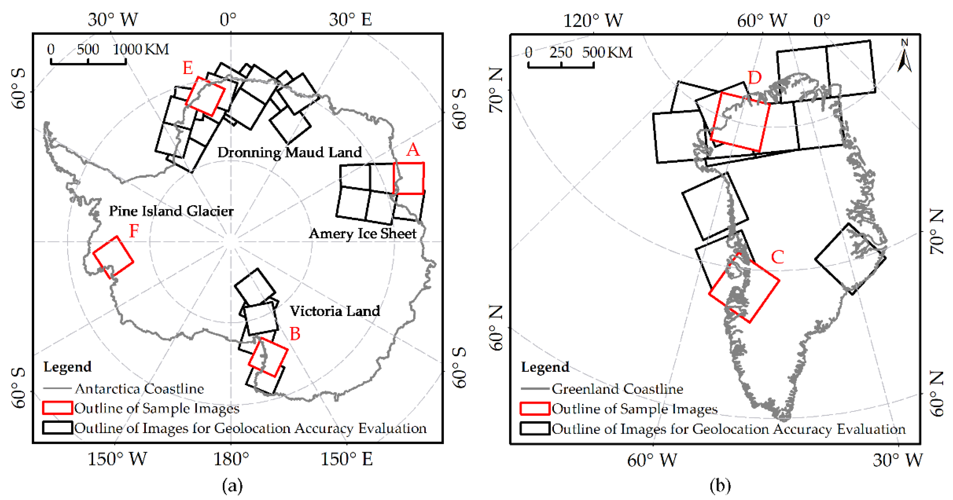
BNU-1 Imagery. BNU-1 has obtained more than 6000 images covering Antarctica and Greenland since it was launched. It provides the observations in panchromatic, blue, green, red, and red-edge spectral bands. Twenty-eight images of Antarctica and fifteen images of Greenland in the panchromatic band were collected for geolocation and accuracy evaluation. As shown in Figure 1, the images of Antarctica are distributed over the Amery Ice Shelf, Victoria Land, Dronning Maud Land, and Pine Island Glacier. The images of Greenland cover the west and north of Greenland.
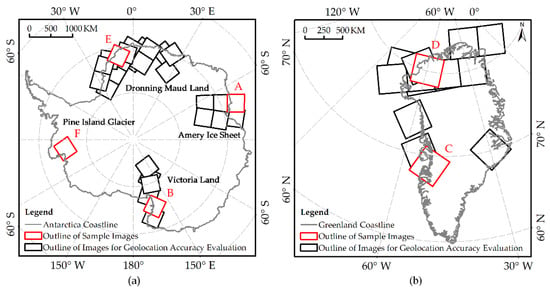
Figure 1.
Distributions of the sample images of BNU-1 for (a) Antarctica and (b) Greenland. Black and red rectangles refer to the footprints of 43 sample BNU-1 image scenes, in which red rectangles show the 6 Sample Images (A–F) used for the analysis in this study. Sample Images A–F were acquired for the Amery Ice Shelf on 8 October 2019, Victoria Land on 11 October 2019, Greenland on 7 July 2020, Greenland on 18 July 2020, Dronning Maud Land on 18 December 2019, and Pine Island Glacier on 28 December 2019, respectively.
MODIS Imagery. MODIS is a key instrument onboard the Terra and Aqua satellites, which were launched on 18 December 1999, and 4 May 2002, respectively, providing global coverage every one to two days. Since the MODIS sensor has high geolocation accuracy (50 m for one standard deviation) [4] and a daily revisit capability, we used MOD02QKM and MYD02QKM products as the reference images for the geometric correction of the BNU-1 images in this study. The geolocation error of MOD02QKM (MYD02QKM) is 50 m or better, which is finer than the pixel size of the MODIS image [13,23,24]. It is reasonable to use MODIS images as the reference data in this study since the spatial resolution of BNU-1 images is 80 m.
Coastline dataset. We used the high-resolution vector polylines of the Antarctic coastline (7.4) [25] of 2021 from the British Antarctic Survey (BAS). We also used the MEaSUREs MODIS Mosaic of Greenland (MOG) 2005, 2010, and 2015 Image Maps, Version 2 [26] from the NASA National Snow and Ice Data Center (NSIDC) to obtain the Greenland coastline. We evaluated the geolocation error of the BNU-1 image visually by comparing the coastline dataset with the geolocation of the BNU-1 image.
3. Methods
There are two steps for geolocating the BNU-1 images in this study. The first step is geometric calibration. In this step, a geometric calibration model is constructed to transform the image coordinates to geographic coordinates. The images with geographic coordinates are the BNU-1 Level 1A (L1A) product. The second step is the geometric correction. The geolocation errors of the BNU-1 L1A product are corrected by an automated geometric correction method in this step. This method is designed to correct the geolocation errors of the images of polar regions where surface textures rarely exist. The corrected BNU-1 L1A product, which has high geolocation accuracy, is named the BNU-1 Level 1B (L1B) product.
3.1. Geometric Calibration Model
3.1.1. Description of Geometric Calibration Model
A rigorous geometric calibration model was constructed for transforming the image coordinates to the geographic coordinates for the BNU-1 images. The timing, position, and altitude of satellites and camera position parameters are used as inputs of the model. The model is shown as follows [27]:
where t is the scanning time of an imaginary line. indicates the coordinates of the Global Positioning System (GPS) antenna phase center, which are measured by a GPS receiver on the satellite in the WGS84 coordinate system (derived from ECEF) at t. m is the scale factor determined by the orbital altitude. , and are the rotation matrix of the coordinate system from J2000 to WGS84 at t, the rotation matrix from the satellite’s body-fixed coordinate system to J2000 coordinate system at t, and the rotation matrix from the camera coordinate system to the satellite’s body-fixed coordinate system, respectively. is the coordinates of the GPS antenna phase center in the satellite’s body-fixed coordinate system. is the translations of the origin of the camera coordinate system relative to the satellite’s body-fixed coordinate system. represents the value of the coordinates of point (x, y) corresponding to the detector direction angle model composed of the camera’s principal point, focal length, charge coupled device (CCD) installation position, and lens distortion. represents the ground coordinates of the point (x, y) in the World Geodetic System 1984 (WGS84) coordinate system.
and describe the directional angle of point (x, y) in the camera coordinate system [27,28,29], and this can be calculated by Equation (2), where f is the focal length of the camera.
This step is conducted on the Windows Server 2016 Standard operating system on the Intel(R) Xeon(R) Gold 5220R CPU @2.20 GHz, 256 GB RAM. It is a whole-day unattended automatic data production system.
3.1.2. Uncertainty Evaluation of Geometric Calibration Model
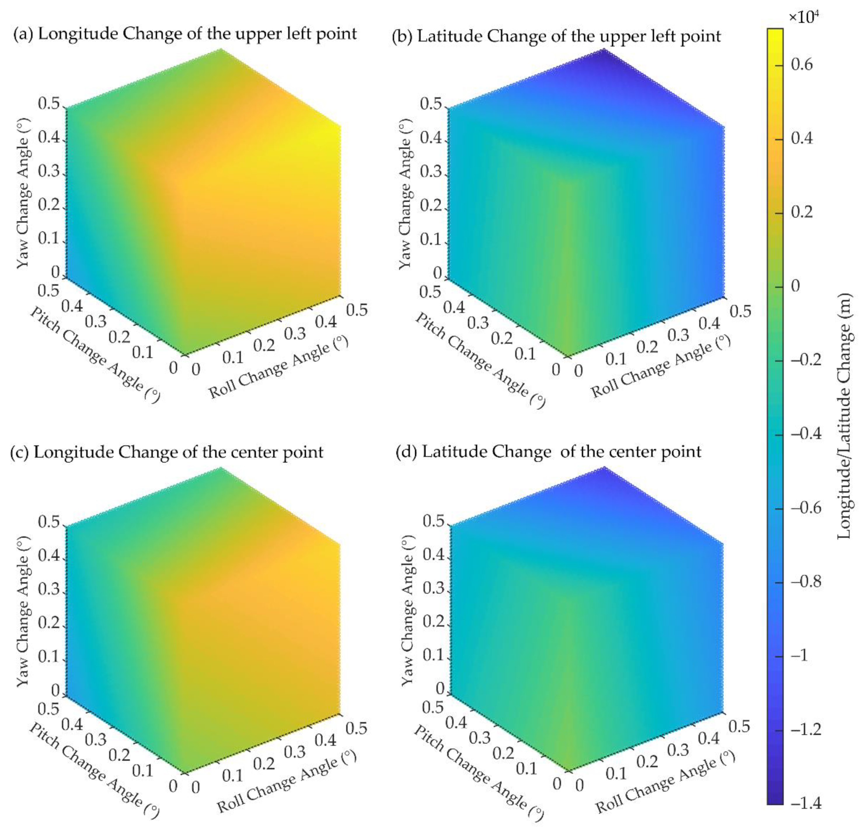
In addition to systematic errors, the geolocation of acquired images is also affected by random errors. The satellite imaging process is affected by various complex conditions such as attitude adjustment, attitude measurement accuracy, and imaging environment. In addition, as a microsatellite, BNU-1′s low cost and the imaging environment of polar regions limit, to a certain extent, the overall accuracy and stability of the measurement equipment of attitude and position. Moreover, due to the wide swath of BNU-1′s camera, the imaging time of its single-scene image is long. As the satellite attitude is adjusted along the imaging, random errors in attitude measurement cause random geolocation errors in single-scene images and multiple-scene images. Since the measurement error of GPS can be regarded as translation error (Equation (1)), which is equivalent to the satellite rotating at a small angle, we only designed and carried out an experiment to simulate the influence of the satellite’s attitude angle change on the geolocation change through Equation 1. The satellite’s attitude is determined by the roll angle, pitch angle, and yaw angle. We randomly selected an image and simulated the angles of roll, pitch, and yaw, which changed from 0° to 0.5° with a step size of 0.1°, to obtain 216 (6 * 6 * 6) groups of geolocations. The quintic polynomial method was used to fit the scatter plot.
3.2. Automated Geometric Correction Processing Method
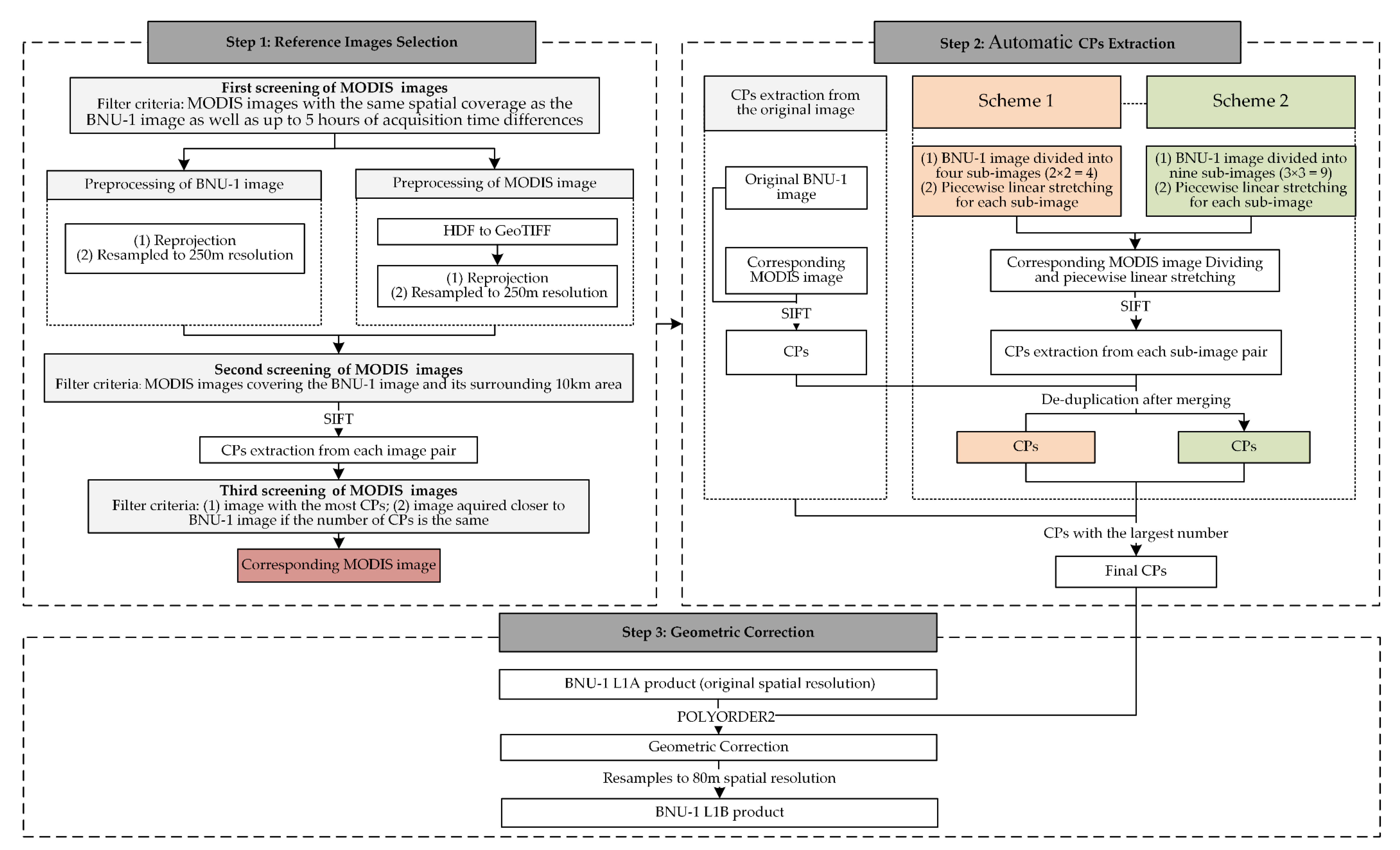
Since the space environment is complex and variable during satellite launch and operation [15,28,30,31], the geographic coordinates calculated by geometric calibration models with the pre-launch laboratory measurement parameters usually have geolocation errors of about several hundred meters to several kilometers [32,33]. In addition, the random error of the attitude measurement cannot be eliminated due to the lack of ground control points in polar regions. An automated geometric correction method based on CPs matching was developed to improve the geolocation accuracy of the BNU-1 L1A product. There are three steps involved in the method. Firstly, we selected the reference image with a high geolocation accuracy for the BNU-1 images. Then, the Scale Invariant Feature Transform algorithm (SIFT) [33] was used to extract the CPs from both the BNU-1 image and the corresponding reference image. Finally, geometric correction was conducted on the BNU-1 image based on the CPs. The flow chart is shown in Figure 2. Our experiment was conducted on the operating system of Windows 10 on the Intel(R) Core (TM) i5-5200 CPU @2.20 GHz, 8 GB RAM. We used the programming language of python2.7 to implement the one-stop processing of the automatic geometric correction. In this process, the programming language of MATLAB was used to realize SIFT algorithm, and the software of ArcGIS 10.6 was used to realize data preprocessing and geometric correction.
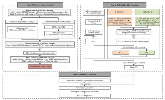
Figure 2.
The flowchart for the automated geometric correction processing method of BNU-1 L1A product.
3.2.1. Step 1: Reference Images Selection
There were three criteria for selecting a reference image. Firstly, we selected the MODIS images with the same spatial coverage as the BNU-1 image as well as up to 5 h of different acquisition times. Secondly, the MODIS images covering the BNU-1 image and its surrounding 10 km area were chosen (one BNU-1 image corresponds to multiple MODIS images). Thirdly, the SIFT algorithm was adopted to extract the CPs from each image pair, where the BNU-1 image and the MODIS image are the target image and the reference image, respectively. The MODIS image with the most CPs was used as a reference image for the geometric correction. If more than one MODIS image has the highest number of CPs, the one whose acquisition time is closer to the BNU-1 image’s acquisition time is preferred as the reference image. The reference image used for geometric correction of the BNU-1 image is referred to as the corresponding MODIS image hereinafter.
3.2.2. Step 2: Automatic CPs Extraction
The amount and spatial distribution of CPs are key factors for geometric correction because they have direct impacts on the geometric correction accuracy of the corrected images. In this study, we applied the SIFT algorithm based on MATLAB language to extract the CPs automatically from the BNU-1 L1A and the corresponding MODIS image. Due to the lack of texture features of snow and ice surfaces at high latitudes, CPs extracted from the original image pair are usually not sufficient for correcting the geolocation errors. When the number of CPs extracted from the image pair needs to be increased, image division and image enhancement methods are used to enhance the texture features of satellite images [1,21,22,34].
The combination of an image division method and an image enhancement method was applied to highlight surface features of the BNU-1 and MODIS images in this study. The extraction of CPs was carried out in three steps in Step 2 (Figure 2). Firstly, we extracted the CPs from the original BNU1-1 image and the corresponding MODIS image by using the SIFT algorithm. The Euclidean distances between each pair of CPs from the image pair were calculated. To avoid mismatches of the points, we eliminated the largest 10% points in the Euclidean distance. Secondly, we extracted the CPs from the image pair after processing by different image division schemes. The paired images were divided into 2 × 2 = 4 (Scheme 1) and 3 × 3 = 9 (Scheme 2) sub-images [22]. Then, an adaptive piecewise linear enhancement consisting of three rules for low, middle, and high reflectance ranges was used to enhance each sub-image [34]. We extracted the CPs from all the pairs of the sub-images again by the SIFT algorithm. The largest 30% of the extracted CPs in Euclidean distance were eliminated in this step. Finally, the CPs extracted in the above two steps were merged and de-duplicated to obtain the CPs with the largest number, which were taken as the final CPs for the geometric correction.
3.2.3. Step 3: Geometric Correction
This study performed the geometric correction of the BNU-1 L1A product with the original spatial resolution (74 m) by using a quadratic polynomial (POLYORDER2) model in ArcGIS 10.6 software. We obtained the BNU-1 L1B product by resampling the geolocation error-corrected image to 80 m spatial resolution using the nearest resampling method.
3.3. Geolocation Accuracy Evaluation
To evaluate the geolocation accuracy of the BNU-1 L1A/L1B product, we re-extracted the CPs from the BNU-1 L1A/L1B product by the SIFT algorithm as the verification points and calculated the root mean squared error (RMSE) of the verification points:
where is the number of points participating in the accuracy evaluation, and represent the residuals of the i-th extracted points from the BNU-1 and the reference MODIS image in the X and Y coordinates, respectively.
4. Results
4.1. Geolocation Accuracy of the BNU-1 L1A Product
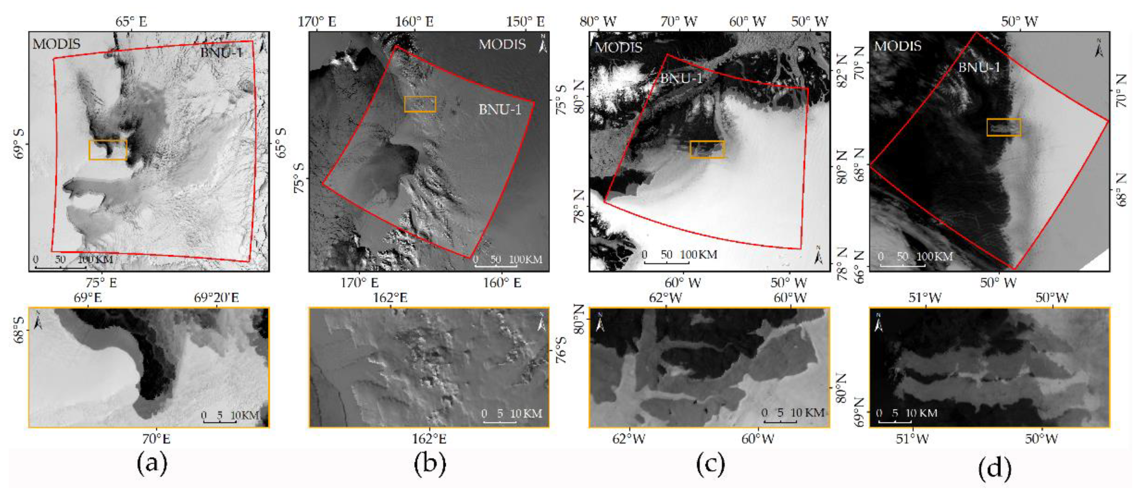
The BNU-1 L1A images with 50% transparency are superimposed on the corresponding MODIS images in Figure 3. The sub-figures (a), (b), (c), and (d) correspond to the Sample Images A, B, C, and D shown in the red box in Figure 1. The prominent features in the images, such as coastlines, rocks, sea ice, etc., are blurred, indicating the mismatch of the geometric position between the BNU-1 images and the corresponding MODIS images. Obvious geolocation errors are observed in the BNU-1 L1A images. Table 1 shows the geolocation errors of the 42 scene BNU-1 L1A images. The errors of the BNU-1 L1A images range from 3 to 20 km, with an average of about 10 km. The geolocation errors of the sub-graphs in Figure 3a–d are 6544.83 m, 7919.60 m, 15,071.02 m, and 7778.63 m, respectively (Table 1).
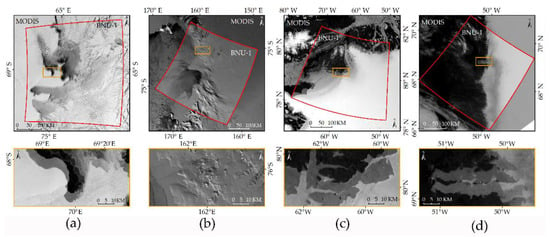
Figure 3.
BNU-1 L1A images superimposed on the corresponding MODIS images. Red polygons refer to the outline of the Sample Image scenes shown in Figure 1. (a) Sample Image A; (b) Sample Image B; (c) Sample Image C; (d) Sample Image D. The images in the yellow boxes below are the enlarged versions of the part in the sample images.

Table 1.
Geolocation errors of the BNU-1 L1A/L1B product (unit: meter).
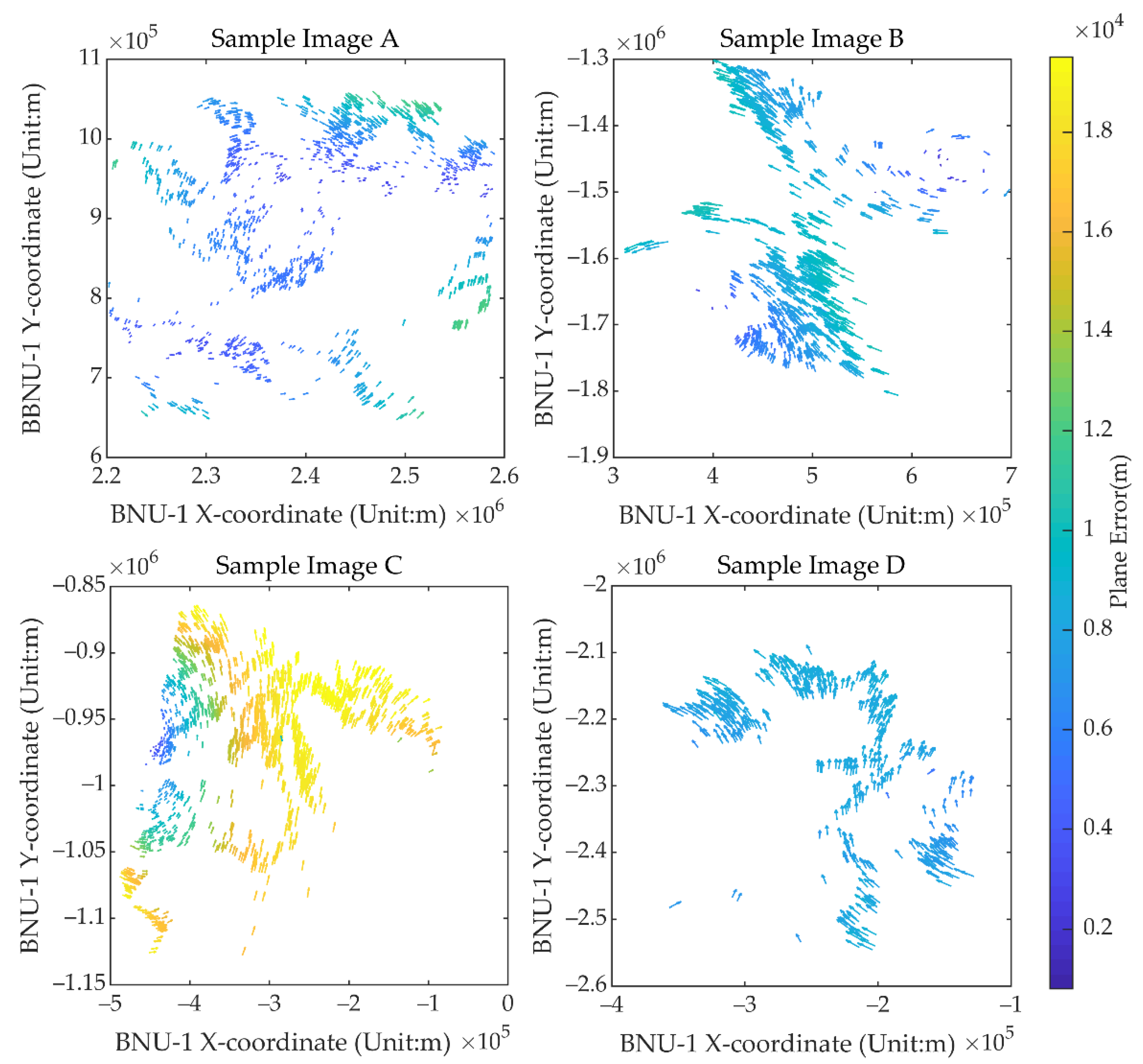
Figure 4 shows the distributions of the geolocation errors of the CPs in the X and Y directions for each image shown in Figure 3. The length and direction of the vectors in Figure 4 represent the magnitude and direction of the CPs’ geolocation errors. The directions and the magnitude of geolocation errors for each image are not consistent (Figure 4). For example, the CPs’ geolocation errors of Sample Image A, B, and D are less than 12 km, while most CPs’ geolocation errors of Sample Image C are up to 19 km. And the geolocation errors in the middle part of Sample Image A are smaller than the errors in the edges of the image, while Sample Image B shows a quite different distribution of geolocation errors. In addition, the direction of the geolocation errors of the CPs shown in Sample Images B, C, and D are also different from the center to the periphery of the images. The CPs’ geolocation errors within an image also vary significantly. For example, geolocation errors in Sample Image C are less than 2000 m in the center-west parts and more than 15,000 m in the east and southwest parts (Figure 4). The results illustrate that the distribution of the CPs’ geolocation errors varies in each image and indicates that some local distortions exist in the BNU-1 L1A product.
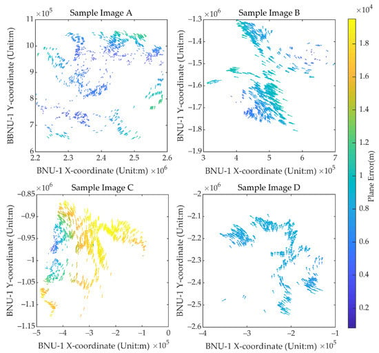
Figure 4.
Displacement vectors of the CPs for the four sample BNU-1 L1A images and the corresponding MODIS images in Figure 3. The vectors start and end at the CPs’ coordinates in polar stereographic projection on the BNU-1 L1A images and the corresponding MODIS images, respectively. The color of the vectors represents the error magnitude according to the legend.
4.2. Uncertainty Evaluation of Geolocation of BNU-1 L1A Product
Figure 5 shows the three-dimensional scatter diagram of the influence of the change in the satellite’s attitude angle—roll, pitch, and yaw—on the geolocation change. The results show that when the angles of roll, pitch, and yaw change from 0.1° to 0.5°, the geolocation change in the upper left corner point of the image changes from −6256 m to 6594 m in the longitude and from −13,915 m to −112 m in the latitude. Similarly, the geolocation change in the center point of the image changes from −6431 m to 4998 m in the longitude and from −11,889 m to −251 m in the latitude. These geolocation changes are non-linear (Figure 5). Under imaging conditions in polar regions, the random error of attitude measurement cannot be eliminated due to the lack of ground control points in polar regions [28]. To obtain high-precision geolocation products, it is necessary to add CPs to the image for geometric correction. Since there are few textures observed on high-reflectance ice and snow surface in polar regions, the extraction of CPs is the key to geometric correction.
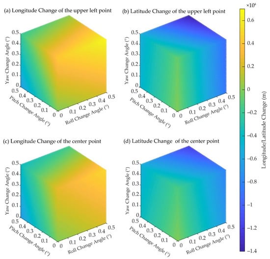
Figure 5.
Three-dimensional scatter diagram of the influence of the satellite’s attitude angle change on the geolocation change. (a,b) show the impact of the satellite’s attitude changes on the longitude change and the latitude change of the upper left corner point of the image, respectively. (c,d) show the impact of the satellite’s attitude changes on the longitude change and the latitude change of the center point of the image, respectively. The color of the scatters represents the longitude/latitude change according to the legend.
4.3. Influence of Image Division and Enhancement on the CPs Extraction
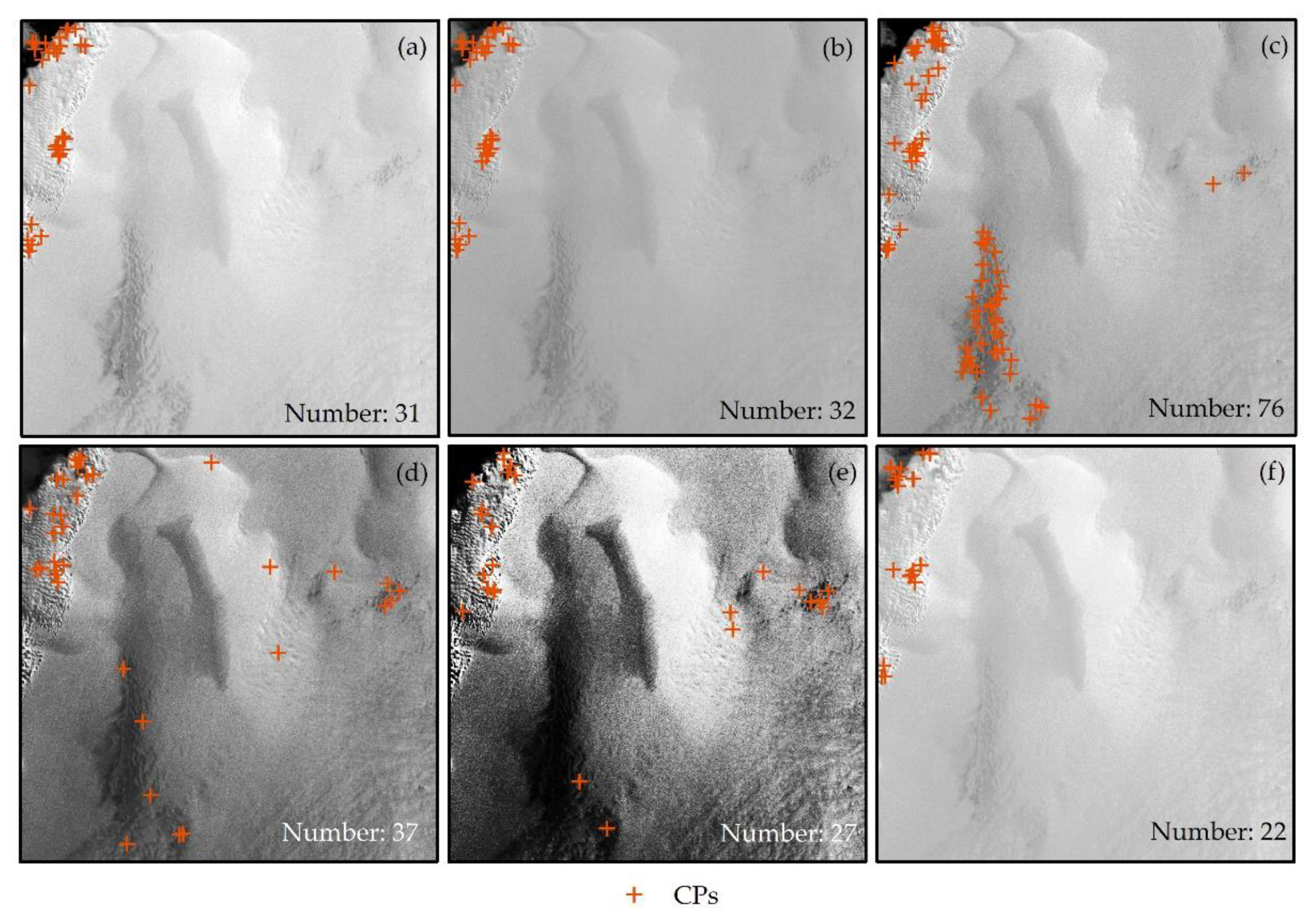
Sample Image E is a typical image for polar regions. Most of the features in the image are ice sheets and snow with limited boundary features, and only a few of them are sea ice with well-defined boundaries. However, due to the high reflectance of ice and snow surfaces in polar regions, the textures of the ice sheet and snow can rarely be observed in images. The ice sheet area of Sample Image E is a good case for evaluating the effectiveness of various image enhancement methods for increasing the control points on the ice sheet. Five image enhancement methods, which are linear enhancement, piecewise linear enhancement, Gaussian enhancement, equalization enhancement, and square root enhancement, were applied to enhance Sample Image E. Figure 6 shows the distributions of CPs extracted from the images enhanced by different image enhancement methods. The numbers of CPs extracted from the original image and the image stretched by the five enhancement methods were 31, 32, 76, 37, 27, and 22, respectively. By comparing these five enhancement methods, we found that the piecewise linear enhancement method makes the surface textures in the interior of the ice sheet more distinct, and as a result, the most CPs were extracted from the image. Therefore, the piecewise linear enhancement (Figure 6c) is considered to be more suitable for enhancing the images of polar regions.
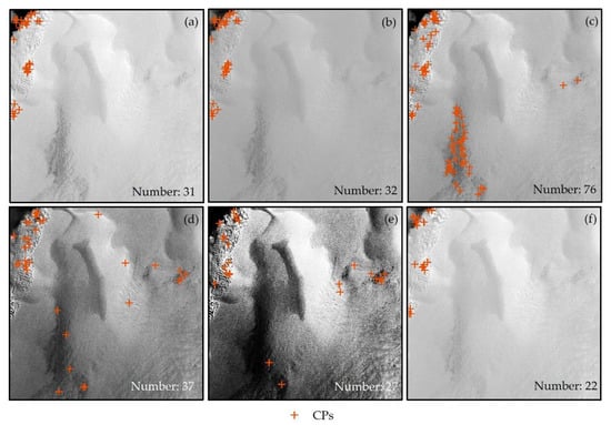
Figure 6.
Comparisons of the number and distribution of CPs in the original image (a) and the image adopting different enhancement methods: (b) Linear; (c) Piecewise Liner; (d) Gaussian; (e) Equalization; (f) Square Root.
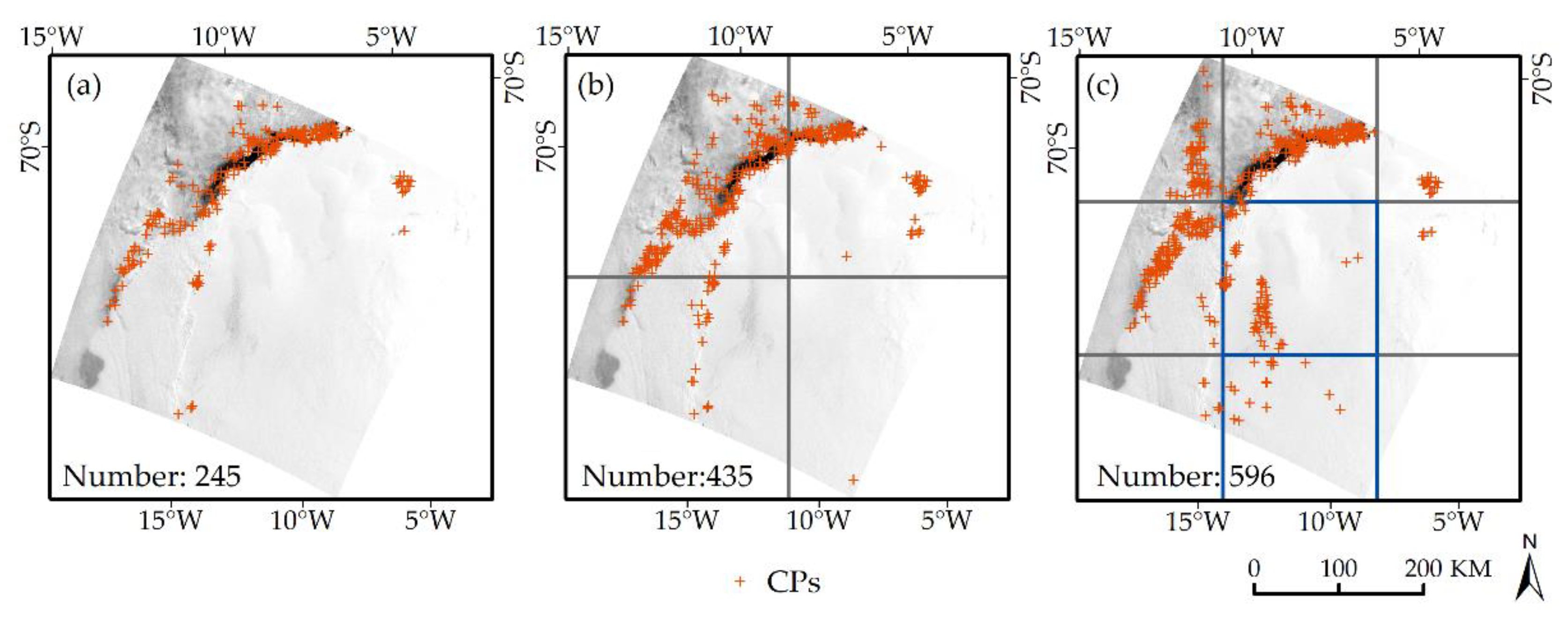
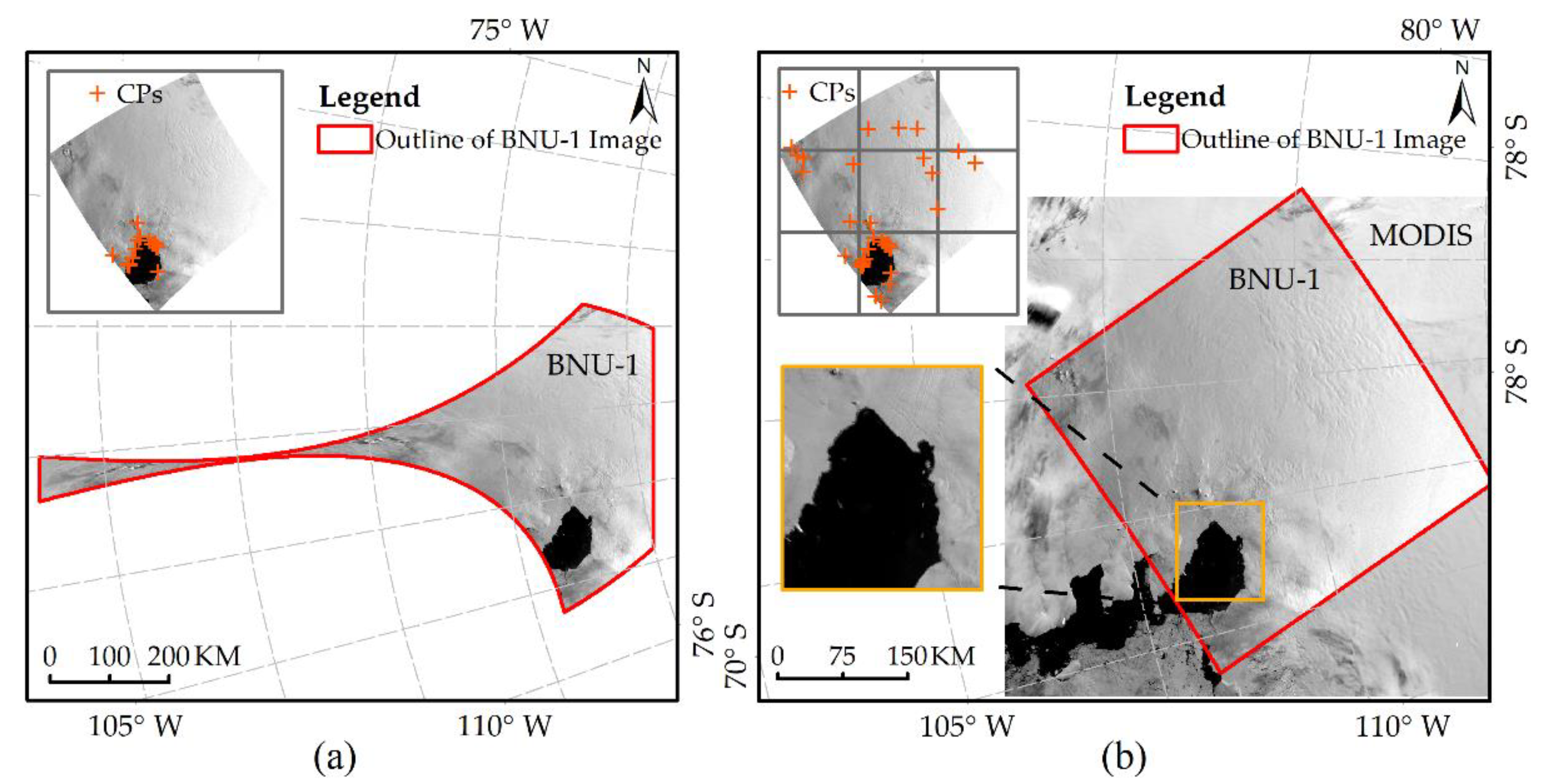
Sample Image E was also used to assess the influence of image division on CPs extraction. The image was divided into four sub-images (Scheme 1) and nine sub-images (Scheme 2) and then each sub-image was individually enhanced with the piecewise linear stretching method. Figure 7 shows the distribution of CPs extracted from the original image by Scheme 1, and by Scheme 2, respectively. The number of extracted points are 245, 435, and 596, respectively. More CPs are extracted in the center and the lower right corner of the image (the blue border area) divided by Scheme 2 (Figure 7c) compared to the original image (Figure 7a) and the image divided by Scheme 1 (Figure 7b). As shown in Table 2, the amount of CPs extracted from the image increases by 30% to 182% when the image division and piecewise linear enhancement were applied to the images. However, this does not mean we can get more CPs if the image is divided into more sub-images. The amount of CPs extracted from the Sample Image A, B, C, and D is less when Scheme 2 is applied to divide these images.
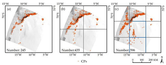
Figure 7.
Schematic diagram of the number and distribution of the CPs extracted by different division strategies. (a) The original image; (b) Scheme 1; (c) Scheme 2.

Table 2.
The number of the extracted CPs with different image division schemes.
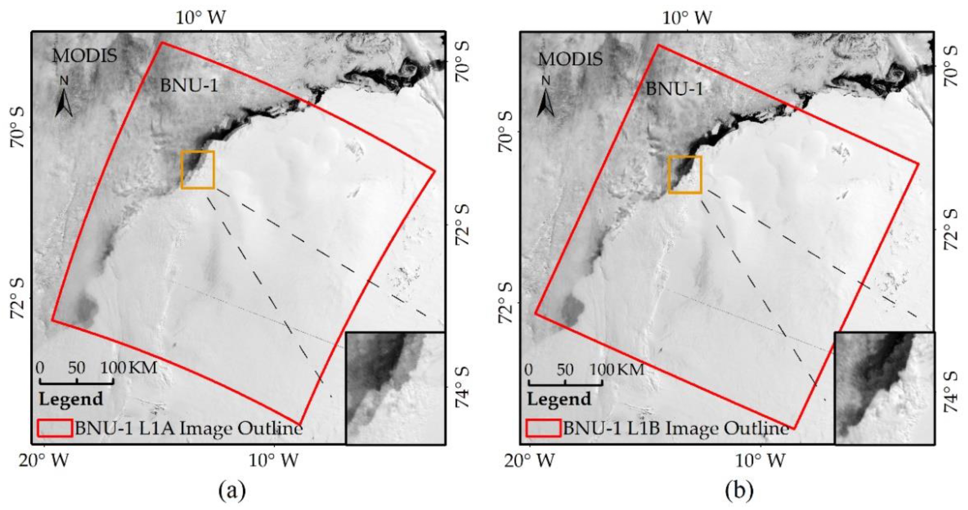
The CPs extracted from Sample Image E were used to correct the geolocation errors of the image. The BNU L1A/L1B image with 50% transparency is superimposed on the corresponding MODIS image in Figure 8. There is a distinct displacement between the BNU-1 L1A image and the MODIS image, while the displacement between the BNU-1 L1B image and the MODIS image can barely be discerned. This result indicates that the geolocation correction method improves the geolocation accuracy of the BNU-1 L1A product.
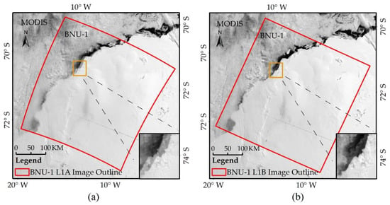
Figure 8.
The BNU-1 images superimposed on the corresponding MODIS images. (a) BNU-1 L1A image; (b) BNU-1 L1B image. Red boxes refer to the extent of the BNU-1 L1A/L1B images.
In addition to Sample Image E, Sample Image F was also selected to evaluate the effectiveness of the CPs extraction scheme proposed. Most of the areas of Sample Image F are covered by the ice sheet, and only a few areas are fjords. Figure 9 shows the image after geometric correction of the BNU-1 L1A image using the CPs extracted from the original image and the optimal control point extraction scheme (Scheme 2). The CPs extracted from the original image are few and unevenly distributed. If these points are directly used for geometric correction of the BNU-1 L1A image, the corrected image will be severely distorted (Figure 9a). More, and more evenly distributed CPs are extracted of the image divided by Scheme 2 (Figure 9b) compared to the original image (Figure 9a). The corrected BNU-1 image overlaps well with the MODIS image (Figure 9b).
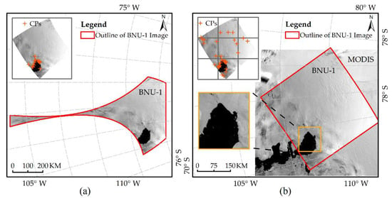
Figure 9.
BNU-1 image after geometric correction of the BNU-1 L1A image using the CPs extracted from the original image (a) and Scheme 2 (b). The corrected image with 50% transparency is superimposed on the corresponding MODIS image in (b).
4.4. Geolocation Accuracy of the BNU-1 L1B Product
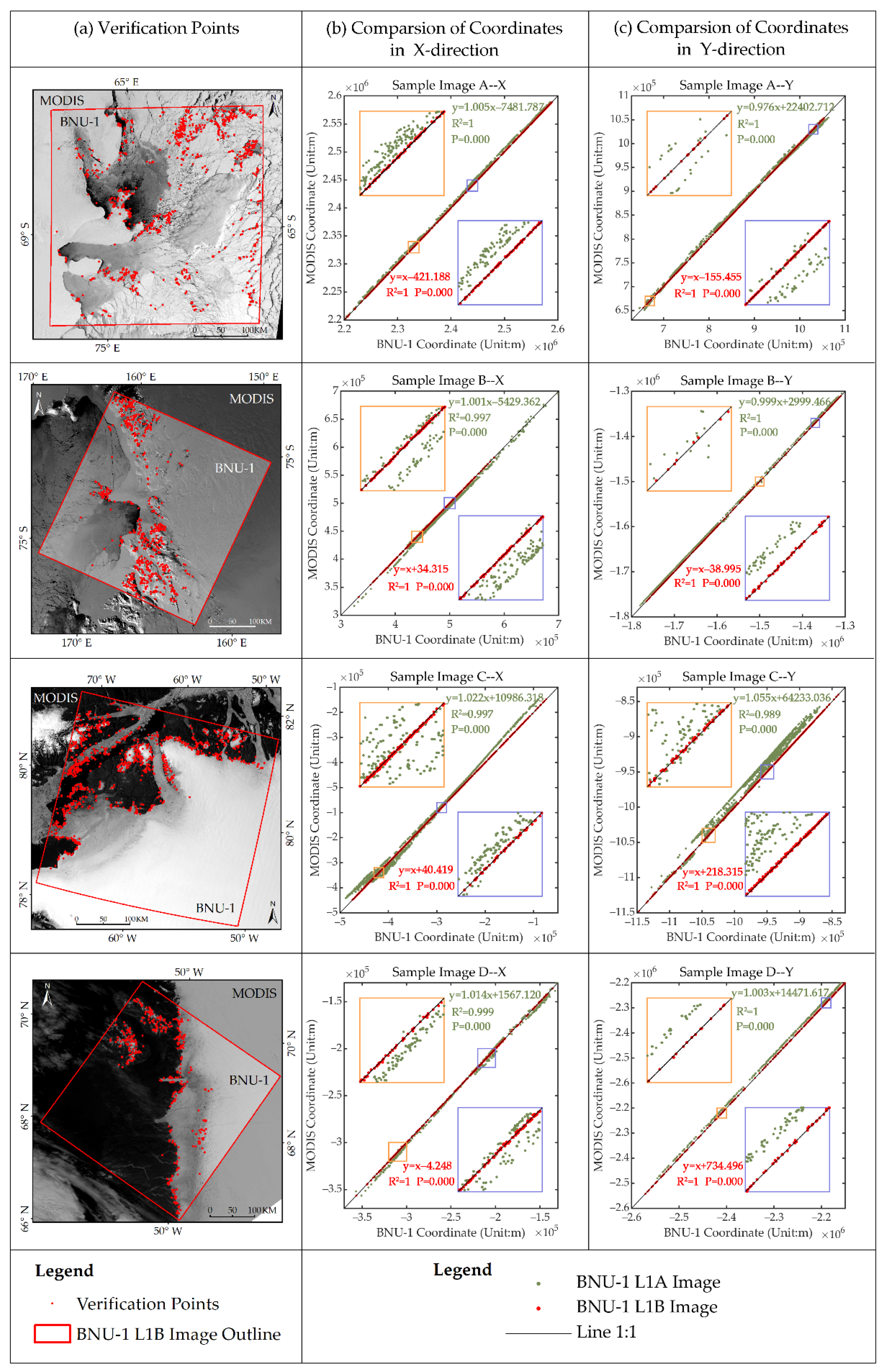
The verification points used to evaluate the geolocation errors of the BNU-1 L1B product for the Sample Images A, B, C, and D are shown in Figure 10a. We compared the coordinates of verification points in the BNU-1 L1A/L1B images with those in the corresponding MODIS images in Figure 10b, c. The verification points extracted from the BNU-1 L1A product (green dots) are distributed on one side of the 1:1 line (black diagonal line), which means that geolocation errors exist in the BNU-1 L1A product, while the verification points extracted from the BNU-1 L1B product (red dots) are almost scattered on the 1:1 line. We fitted the linear relationships between the coordinates of the verification points from BNU-1 L1A/BUN-1 L1B and the MODIS image. The regression coefficients, intercepts, and determined coefficients of the relationship fitted by the BNU-1 L1B product are significantly better than those fitted by BNU-1 L1A. The coordinates of the points from the BNU-1 L1B product show great consistency with the coordinates from the MODIS images. The geolocation accuracy of the BNU-1 L1B images was improved significantly. After geometric correction, the average geolocation error was reduced from 10,480.31 m to 301.14 m (Table 1).
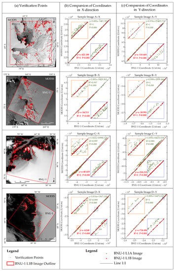
Figure 10.
Spatial distribution of the verification points for accuracy evaluation of BNU-1 L1B Sample Images A, B, C, and D (a); and the coordinates comparison of the verification points of BNU-1 L1A/L1B Sample Image A, B, D, and E and their corresponding MODIS images, in X-direction (b) and Y-direction (c), respectively. Green and red dots represent the verification points on the BNU-1 L1A image and the BNU-1 L1B image, respectively. The black diagonal line in the sub-figures represents that the coordinates of points in the BNU-1 image are almost equal to those in the corresponding MODIS image. The two small graphs in each sub-graph are the enlarged version of the orange and blue rectangular areas on the black diagonal line.
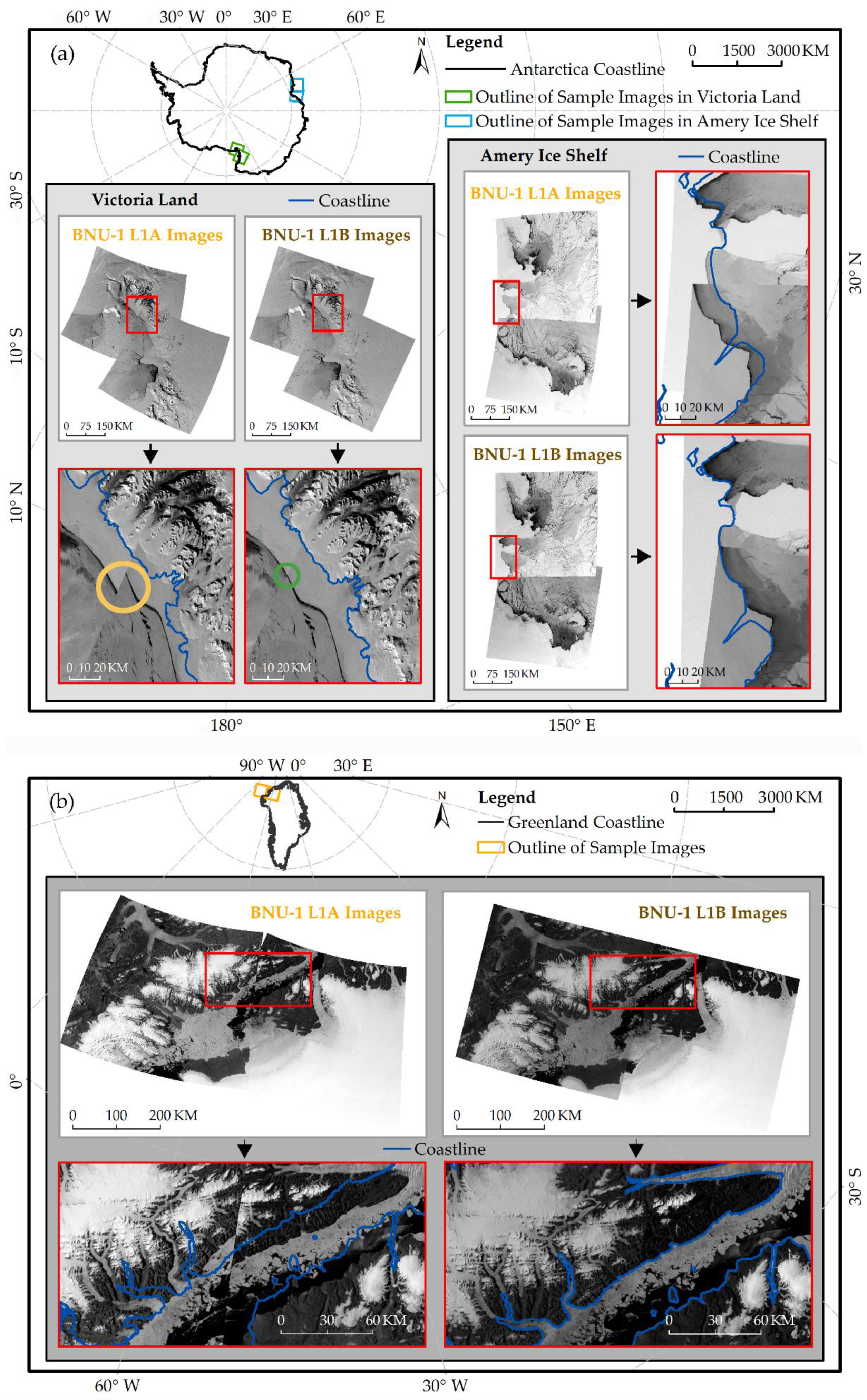
We obtained the image mosaics of the Amery Ice Shelf and Victoria Land in Antarctica and northern Greenland in the panchromatic band of BNU-1 (Figure 11). Mismatches in the coastlines were found in the image mosaics from the BNU-1 L1A product. However, the coastlines in the image mosaics from the BNU-1 L1B product are consistent with the existing coastline dataset [25]. Even though the junction of adjacent images in the image mosaic from the BNU-1 L1B product has greatly improved coherence compared to the BNU-1 L1A product, the BNU-1 L1B product still has an average geolocation error of ~300 m. For example, the discontinuous waters at the junction are found in Victoria Land (obvious mismatches in the yellow circle in Figure 11a) from the BNU-1 L1A product, while the mosaic from the BNU-1 L1B product has consistent waters at the junction regions (slight mismatches in the green circle in Figure 11a).
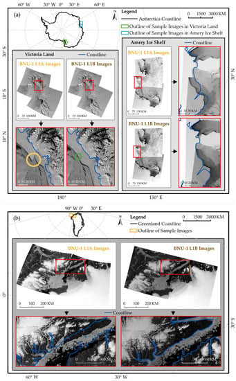
Figure 11.
Mosaic of the panchromatic band images of some BNU-1 L1A/L1B Sample images: (a) Antarctica; (b) Greenland. The blue lines represent the existing coastline dataset.
5. Discussion
Although microsatellites have the advantages of compactness, low cost, and flexibility, their flight attitude may be unstable occasionally and the equipment measuring the attitude and position may be inaccurate or perform poorly, which leads to large geolocation errors in the images [35]. For example, the geolocation errors in UNIFORM-1′s visible images are 50–100 km [35]. The BNU-1 L1A product has smaller geolocation errors, but the average geolocation error can still be up to 10 km, which is close to that of the Luojia 1-01 data [30].
The non-parametric geometric correction methods are widely applied to geolocation correction of images without distinguishing the error sources [16,31], such as HJ-1A/B CCD images [36] and Unmanned Aerial Vehicle (UAV) images [37]. The geolocation accuracy of these geometric correction methods relies mainly on adequate CPs. However, the limited texture features of the ice and snow surface in polar images make it difficult to extract the CPs. Some studies prove that image division and image enhancement have the ability to increase the amount of extracted CPs [1,21,22,34]. However, images used by these previous studies are from low- and mid- latitudes and contain rich land surface features. The correction for polar images with few texture features is rarely documented. This study proposes the geometric correction method to reduce the geolocation errors of the visible images for polar regions. The results indicate that piecewise linear enhancement highlights more surface features of ice and snow surfaces than other image enhancement methods. Some other studies have also proved that piecewise linear enhancement is effective in highlighting more texture features of the ice and snow surfaces in polar images [34]. More CPs can be observed after the image pair is processed by image division and piecewise linear enhancement. Different division schemes can be adopted to obtain more CPs for different image pairs.
In addition, we compared the geolocation accuracy of Sample Image A–F after the correction through the CPs extracted from the original image and the geolocation accuracy after correction through the optimal CPs extraction scheme (Table 3). It was found that the geolocation accuracy of Sample Image A–E was not significantly improved. The geolocation accuracy of Sample Image A–E after geometric correction based on the CPs extracted from the original image was close to the level of 250 m (the pixel size of MODIS image), and it was difficult to further improve by adding CPs on this basis. However, for some images where the ice sheet is widely distributed, such as Sample Image F, the proposed method effectively prevents the distortion of the corrected image caused by the lack of CPs on the ice sheet by adding CPs. The increase in CPs can remarkably improve the geolocation accuracy of such images. Therefore, the automatic geometric correction method proposed in this study is of great significance for the correction of images in polar regions with rare feature points.

Table 3.
Comparison of the geolocation accuracy of the BNU-1 images corrected through different CPs extraction Scheme.
Although the method presented in this study has some advantages in correcting the geolocation errors of polar images, it also has its limitations. For example, only two division schemes were applied in the BNU-1 images, and the division fractions for different images are still worth further study. Besides, the geolocation accuracy of some sub-images with relatively uniform surface features is difficult to improve by using the proposed method. This indicates that the SIFT algorithm has its limitation for finding more CPs. Therefore, it is necessary to explore some other CPs extraction methods for increasing the number of CPs. Since deep learning methods have been widely used in image registration [38,39], it is worth exploring the possible application of deep learning methods on CPs extraction from the images of polar regions.
6. Conclusions
In this study, we present the geolocation method for BNU-1 images including two steps. For the first step, a rigorous geometric calibration model was applied to transform the image coordinates to the geographic coordinates for the BNU-1 images. The images geolocated by the geometric calibration model are the BNU-1 L1A product. For the second step, an automated geometric correction method was used to reduce the geolocation errors of the BNU-1 L1A product. The images corrected by the geometric correction method are the BNU-1 L1B product.
The geometric correction method is commonly used for improving the geolocation errors of the visible image. However, the texture features of the ice and snow surfaces are rarely seen in polar images, which makes it difficult to find the CPs. The combination of the image division method and piecewise linear image enhancement method was applied to the BNU-1 L1A product and the corresponding MODIS images, and the results indicate that the CPs extracted increased by 30% to 182%, which can effectively improve the geometric accuracy of the BNU-1 images.
The geolocation method was applied to 28 images of Antarctica and 15 images of Arctic regions. The average geolocation error was reduced from 10 km to ~300 m. The coastlines in the image mosaics from the BNU-1 L1B product were consistent with the coastline dataset. These results suggest that the geolocation method has the ability to improve the geolocation errors of BNU-1 images and other satellite images in polar regions.
Author Contributions
Conceptualization, X.C.; methodology, Y.Z. and Z.C. (Zhuoqi Chen); software, Y.Z.; validation, Y.Z.; formal analysis, Y.Z.; data curation, Y.Z.; writing—original draft preparation, Y.Z. and Z.C. (Zhuoqi Chen); writing—review and editing, Y.Z., Z.C. (Zhaohui Chi), Z.C. (Zhuoqi Chen), F.H., T.L., B.Z. and X.L.; visualization, Y.Z.; supervision, Z.C. (Zhuoqi Chen), X.C.; project administration, X.C.; funding acquisition, X.C. All authors have read and agreed to the published version of the manuscript.
Funding
This research was funded by National Natural Science Foundation of China (Grant No. 41925027), National Key Research and Development Program of China (Grant No. 2019YFC1509104 and 2018YFC1406101), and Innovation Group Project of Southern Marine Science and Engineering Guangdong Laboratory (Zhuhai) (No. 311021008).
Institutional Review Board Statement
Not applicable.
Informed Consent Statement
Not applicable.
Data Availability Statement
The data presented in this study are available on request from the corresponding author.
Acknowledgments
We greatly thank NASA for providing the MODIS Level 1B calibrated radiances data (MOD02QKM and MYD02QKM) (https://ladsweb.modaps.eosdis.nasa.gov/search/, accessed on 11 September 2020), BAS for the high resolution vector polylines of the Antarctic coastline (7.4) (https://data.bas.ac.uk/items/e46be5bc-ef8e-4fd5-967b-92863fbe2835/#item-details-data, accessed on 1 August 2021 ), and NSIDC for the MEaSUREs MODIS Mosaic of Greenland (MOG) 2005, 2010, and 2015 Image Maps, Version 2 (https://nsidc.org/data/nsidc-0547, accessed on 20 October 2020 ). We greatly thank Zhuoyu Zhang for her help with the preprocessing of MODIS images.
Conflicts of Interest
The authors declare no conflict of interest.
References
- Chen, Z.; Chi, Z.; Zinglersen, K.B.; Tian, Y.; Wang, K.; Hui, F.; Cheng, X. A new image mosaic of greenland using Landsat-8 OLI images. Sci. Bull. 2020, 65, 522–524. [Google Scholar] [CrossRef] [Green Version]
- Ban, H.-J.; Kwon, Y.-J.; Shin, H.; Ryu, H.-S.; Hong, S. Flood monitoring using satellite-based RGB composite imagery and refractive index retrieval in visible and near-infrared bands. Remote Sens. 2017, 9, 313. [Google Scholar] [CrossRef] [Green Version]
- Schroeder, W.; Oliva, P.; Giglio, L.; Quayle, B.; Lorenz, E.; Morelli, F. Active fire detection using Landsat-8/OLI data. Remote Sens. Environ. 2016, 185, 210–220. [Google Scholar] [CrossRef] [Green Version]
- Gao, F.; Hilker, T.; Zhu, X.; Anderson, M.; Masek, J.; Wang, P.; Yang, Y. Fusing landsat and MODIS data for vegetation monitoring. IEEE Geosci. Remote Sens. Mag. 2015, 3, 47–60. [Google Scholar] [CrossRef]
- Miller, R.L.; McKee, B.A. Using MODIS Terra 250 m imagery to map concentrations of total suspended matter in coastal waters. Remote Sens. Environ. 2004, 93, 259–266. [Google Scholar] [CrossRef]
- Benn, D.I.; Cowton, T.; Todd, J.; Luckman, A. Glacier calving in greenland. Curr. Clim. Chang. Rep. 2017, 3, 282–290. [Google Scholar] [CrossRef] [Green Version]
- Yu, H.; Rignot, E.; Morlighem, M.; Seroussi, H. Iceberg calving of Thwaites Glacier, West Antarctica: Full-Stokes modeling combined with linear elastic fracture mechanics. Cryosphere 2017, 11, 1283–1296. [Google Scholar] [CrossRef] [Green Version]
- Liang, Q.I.; Zhou, C.; Howat, I.M.; Jeong, S.; Liu, R.; Chen, Y. Ice flow variations at Polar Record Glacier, East Antarctica. J. Glaciol. 2019, 65, 279–287. [Google Scholar] [CrossRef] [Green Version]
- Shen, Q.; Wang, H.; Shum, C.K.; Jiang, L.; Hsu, H.T.; Dong, J. Recent high-resolution Antarctic ice velocity maps reveal increased mass loss in Wilkes Land, East Antarctica. Sci Rep. 2018, 8, 4477. [Google Scholar] [CrossRef] [PubMed]
- Onarheim, I.H.; Eldevik, T.; Smedsrud, L.H.; Stroeve, J.C. Seasonal and regional manifestation of arctic sea ice loss. J. Clim. 2018, 31, 4917–4932. [Google Scholar] [CrossRef]
- Luo, Y.; Guan, K.; Peng, J.; Wang, S.; Huang, Y. STAIR 2.0: A generic and automatic algorithm to fuse modis, landsat, and Sentinel-2 to generate 10 m, daily, and cloud-/gap-free surface reflectance product. Remote Sens. 2020, 12, 3209. [Google Scholar] [CrossRef]
- Singh, L.A.; Whittecar, W.R.; DiPrinzio, M.D.; Herman, J.D.; Ferringer, M.P.; Reed, P.M. Low cost satellite constellations for nearly continuous global coverage. Nat. Commun. 2020, 11, 200. [Google Scholar] [CrossRef]
- Wolfe, R.E.; Nishihama, M.; Fleig, A.J.; Kuyper, J.A.; Roy, D.P.; Storey, J.C.; Patt, F.S. Achieving sub-pixel geolocation accuracy in support of MODIS land science. Remote Sens. Environ. 2002, 83, 31–49. [Google Scholar] [CrossRef]
- Moradi, I.; Meng, H.; Ferraro, R.R.; Bilanow, S. Correcting geolocation errors for microwave instruments aboard NOAA satellites. IEEE Trans. Geosci. Remote Sens. 2013, 51, 3625–3637. [Google Scholar] [CrossRef]
- Wang, M.; Cheng, Y.; Chang, X.; Jin, S.; Zhu, Y. On-orbit geometric calibration and geometric quality assessment for the high-resolution geostationary optical satellite GaoFen4. ISPRS-J. Photogramm. Remote Sens. 2017, 125, 63–77. [Google Scholar] [CrossRef]
- Toutin, T. Review article: Geometric processing of remote sensing images: Models, algorithms and methods. Int. J. Remote Sens. 2010, 25, 1893–1924. [Google Scholar] [CrossRef]
- Wang, J.; Ge, Y.; Heuvelink, G.B.M.; Zhou, C.; Brus, D. Effect of the sampling design of ground control points on the geometric correction of remotely sensed imagery. Int. J. Appl. Earth Obs. Geoinf. 2012, 18, 91–100. [Google Scholar] [CrossRef]
- Jiang, Y.; Zhang, G.; Wang, T.; Li, D.; Zhao, Y. In-orbit geometric calibration without accurate ground control data. Photogramm. Eng. Remote Sens. 2018, 84, 485–493. [Google Scholar] [CrossRef]
- Wang, X.; Li, Y.; Wei, H.; Liu, F. An ASIFT-based local registration method for satellite imagery. Remote Sens. 2015, 7, 7044–7061. [Google Scholar] [CrossRef] [Green Version]
- Feng, R.; Du, Q.; Shen, H.; Li, X. Region-by-region registration combining feature-based and optical flow methods for remote sensing images. Remote Sens. 2021, 13, 1475. [Google Scholar] [CrossRef]
- Goncalves, H.; Corte-Real, L.; Goncalves, J.A. Automatic image registration through image segmentation and SIFT. IEEE Trans. Geosci. Remote Sens. 2011, 49, 2589–2600. [Google Scholar] [CrossRef] [Green Version]
- Wang, L.; Niu, Z.; Wu, C.; Xie, R.; Huang, H. A robust multisource image automatic registration system based on the SIFT descriptor. Int. J. Remote Sens. 2011, 33, 3850–3869. [Google Scholar] [CrossRef]
- Khlopenkov, K.V.; Trishchenko, A.P. Implementation and evaluation of concurrent gradient search method for reprojection of MODIS level 1B imagery. IEEE Trans. Geosci. Remote Sens. 2008, 46, 2016–2027. [Google Scholar] [CrossRef]
- Xiong, X.; Che, N.; Barnes, W. Terra MODIS on-orbit spatial characterization and performance. IEEE Trans. Geosci. Remote Sens. 2005, 43, 355–365. [Google Scholar] [CrossRef]
- Gerrish, L.; Fretwell, P.; Cooper, P. High Resolution Vector Polylines of the Antarctic Coastline (7.4). 2021. Available online: 10.5285/e46be5bc-ef8e-4fd5-967b-92863fbe2835 (accessed on 20 October 2021).
- Haran, T.; Bohlander, J.; Scambos, T.; Painter, T.; Fahnestock, M. MEaSUREs MODIS Mosaic of Greenland (MOG) 2005, 2010, and 2015 Image Maps, Version 2. 2018. Available online: https://nsidc.org/data/nsidc-0547/versions/2 (accessed on 20 October 2021).
- Tang, X.; Zhang, G.; Zhu, X.; Pan, H.; Jiang, Y.; Zhou, P.; Wang, X. Triple linear-array image geometry model of ZiYuan-3 surveying satellite and its validation. Int. J. Image Data Fusion 2013, 4, 33–51. [Google Scholar] [CrossRef]
- Wang, M.; Yang, B.; Hu, F.; Zang, X. On-orbit geometric calibration model and its applications for high-resolution optical satellite imagery. Remote Sens. 2014, 6, 4391–4408. [Google Scholar] [CrossRef] [Green Version]
- Cao, J.; Yuan, X.; Gong, J.; Duan, M. The look-angle calibration method for on-orbit geometric calibration of ZY-3 satellite imaging sensors. Acta Geod. Cartogr. Sin. 2014, 43, 1039–1045. [Google Scholar]
- Guan, Z.; Jiang, Y.; Wang, J.; Zhang, G. Star-based calibration of the installation between the camera and star sensor of the Luojia 1-01 satellite. Remote Sens. 2019, 11, 2081. [Google Scholar] [CrossRef] [Green Version]
- Dave, C.P.; Joshi, R.; Srivastava, S.S. A survey on geometric correction of satellite imagery. Int. J. Comput. Appl. Technol. 2015, 116, 24–27. [Google Scholar]
- Zhang, G.; Xu, K.; Zhang, Q.; Li, D. Correction of pushbroom satellite imagery interior distortions independent of ground control points. Remote Sens. 2018, 10, 98. [Google Scholar] [CrossRef] [Green Version]
- Lowe, D.G. Distinctive image features from scale-invariant keypoints. Int. J. Comput. Vis. 2004, 60, 91–110. [Google Scholar] [CrossRef]
- Bindschadler, R.; Vornberger, P.; Fleming, A.; Fox, A.; Mullins, J.; Binnie, D.; Paulsen, S.; Granneman, B.; Gorodetzky, D. The landsat image mosaic of antarctica. Remote Sens. Environ. 2008, 112, 4214–4226. [Google Scholar] [CrossRef]
- Kouyama, T.; Kanemura, A.; Kato, S.; Imamoglu, N.; Fukuhara, T.; Nakamura, R. Satellite attitude determination and map projection based on robust image matching. Remote Sens. 2017, 9, 90. [Google Scholar] [CrossRef] [Green Version]
- Hu, C.M.; Tang, P. HJ-1A/B CCD IMAGERY Geometric distortions and precise geometric correction accuracy analysis. In Proceedings of the International Geoscience and Remote Sensing Symposium, Vancouver, BC, Canada, 24–29 July 2011; pp. 4050–4053. [Google Scholar]
- Li, Y.; He, L.; Ye, X.; Guo, D. Geometric correction algorithm of UAV remote sensing image for the emergency disaster. In Proceedings of the 2016 IEEE International Geoscience and Remote Sensing Symposium (IGARSS), Beijing, China, 10–15 July 2016; pp. 6691–6694. [Google Scholar]
- Wang, S.; Quan, D.; Liang, X.; Ning, M.; Guo, Y.; Jiao, L. A deep learning framework for remote sensing image registration. ISPRS-J. Photogramm. Remote Sens. 2018, 145, 148–164. [Google Scholar] [CrossRef]
- Ma, L.; Liu, Y.; Zhang, X.; Ye, Y.; Yin, G.; Johnson, B.A. Deep learning in remote sensing applications: A meta-analysis and review. ISPRS-J. Photogramm. Remote Sens. 2019, 152, 166–177. [Google Scholar] [CrossRef]
Publisher’s Note: MDPI stays neutral with regard to jurisdictional claims in published maps and institutional affiliations. |
© 2021 by the authors. Licensee MDPI, Basel, Switzerland. This article is an open access article distributed under the terms and conditions of the Creative Commons Attribution (CC BY) license (https://creativecommons.org/licenses/by/4.0/).

