Technical Note

Visual Localization of the Tianwen-1 Lander Using Orbital, Descent and Rover Images

1
State Key Laboratory of Remote Sensing Science, Aerospace Information Research Institute, Chinese Academy of Sciences, Beijing 100101, China
2
Beijing Aerospace Control Center (BACC), Beijing 100094, China
3
CAS Center for Excellence in Comparative Planetology, Hefei 230026, China
4
University of Chinese Academy of Sciences, Beijing 100039, China
*
Author to whom correspondence should be addressed.
Remote Sens. 2021, 13(17), 3439; https://doi.org/10.3390/rs13173439
Submission received: 21 June 2021 / Revised: 11 August 2021 / Accepted: 25 August 2021 / Published: 30 August 2021
(This article belongs to the Special Issue Planetary 3D Mapping, Remote Sensing and Machine Learning)

Abstract

:
Tianwen-1, China’s first Mars exploration mission, was successfully landed in the southern part of Utopia Planitia on 15 May 2021 (UTC+8). Timely and accurately determining the landing location is critical for the subsequent mission operations. For timely localization, the remote landmarks, selected from the panorama generated by the earliest received Navigation and Terrain Cameras (NaTeCam) images, were matched with the Digital Orthophoto Map (DOM) generated by high resolution imaging camera (HiRIC) images to obtain the initial result based on the triangulation method. Then, the initial localization result was refined by the descent images received later and the NaTeCam DOM. Finally, the lander location was determined to be (25.066°N, 109.925°E). Verified by the new orbital image with the lander and Zhurong rover visible, the localization accuracy was within a pixel of the HiRIC DOM.

Graphical Abstract

1. Introduction

Tianwen-1, China’s first independent Mars exploration mission, was launched from Wenchang Space Launch Center in Hainan province by the Long March-5 heavy-lift carrier rocket on 23 July 2020 (UTC+8) [1]. After about seven months, the Tianwen-1 probe, composed of an orbiter, lander and the Zhurong rover, entered the Martian orbit and then activated the 3000-Newton-thrust orbital-control engine to decelerate the probe on 11 February 2021 (UTC+8), to make the probe captured by the Martian gravity [2]. By moving to the elliptical orbit with a perigee of about 400 km [3], the equipped moderate resolution imaging camera (MoRIC) and the HiRIC acquired images of the Martian surface [4,5,6,7]. The HiRIC is responsible for detailed topographic mapping of the key areas, including the two preselected landing areas [7]. After investigation for preselected landing areas, the landing capsule separated from the orbiter and entered into the phase of Entry, Descent and Landing (EDL). On 15 May 2021 (UTC+8), the landing capsule soft landed successfully in the southern part of Utopia Planitia [8]. According to the lander’s Guidance, Navigation and Control (GNC) system, the landing location was at (25.1°N, 109.9°E) in the planetocentric frame tied to the IAU/IAG 2000 Mars coordinate system [9]. Through two rails, the Zhurong rover was deployed to the Martian surface from the lander platform at 10:40 am (UTC+8), 22 May 2021 [10]. Figure 1 shows the diagram of the Tianwen-1 EDL processes.
Timely and precise lander localization is critical for the mission operations and scientific exploration [11,12,13,14,15]. It provides essential geo-location information for task planning, such as radio communication and scientific object exploration. Moreover, accurate lander location is indispensable to guiding the orbiter to acquire high resolution images of the landing area repeatedly, which aims to perform the repeated monitoring of the landing area in the Tianwen-1 mission.
In previous lunar and Mars missions, the lander localization mainly relied on radio-tracking methods and image-based methods [11,12,13,14,15]. Radio-tracking methods obtained accurate measurements of the Doppler shift of the radio signal from the probe. The localization results in the planetary inertial system can be directly calculated, and then be converted to results in the body-fixed coordinate system [15]. The image-based methods employed the images captured by the payload cameras (e.g., descent camera) on the lander to register with the orbiter image of the landing area by using image matching directly, or landmark feature identification and matching [16]. The lander location in the orbiter image was obtained based on the geometric relationship calculation between payload camera images and the orbiter image. In a series of Chinese lunar exploration missions, the first Chinese lunar soft landing and roving mission, Chang’e-3, landed on Mare Imbrium and released the Yutu rover to the lunar surface successfully in December 2013 [17]. The radio-tracking based method provided timely localization results for mission operations. After downlinking the sequential images captured by the descent camera, the refined location was determined by using the image-based method [9]. In the Chang’e-4 and Chang’e-5 missions, similar localization methods were adopted to the landing location determination [13,14]. For the Yutu and Yutu-2 rovers in China’s lunar rover missions, the dead-reckoning and cross site image matching based visual localization were employed for rover localization [18,19]. These rover-localization methods are also being used in Tianwen-1 mission.
During the EDL of Tianwen-1, the descent cameras installed at bottom of the lander platform were to capture sequential descent images of the landing area. The NaTeCam [20] of the Zhurong rover also captured a 360° panorama of the landing site scene with a pitch angle of −30° on top of the lander after touching down on the Martian surface. However, due to the limitation of the radio transmission time windows and bandwidth, not all image data was downlinked immediately. In data packages downlinked early on 19 May, only a single descent image was included for the quick view of the landing area, and NaTeCam images were captured with a pitch angle of −30° at the landing site. The other NaTeCam images with a pitch angle of −5° were captured and downlinked on 22 May. The downlinked single descent image covered a very small area and has a highly different ground resolution (about 0.05 m/pixel) with the orbital DOM (0.7 m/pixel). Hence, it was not feasible to perform immediate location determination using the single descent image alone at the beginning of mission.
In the Tianwen-1 mission, we performed the visual localization of the Tianwen-1 lander by using the timely orbital, descent and rover images according to the availability of data. The remote landmarks, found in NaTeCam images in horizontal view angle, were identified in the orbital DOM and used to triangulate the lander position as the initial localization result. After completely downlinking the sequential descent images on 29 May, we selected four descent images to refine the initial lander location by using image matching between descent images and the orbital DOM. Finally, the NaTeCam DOM of the landing site was taken to determine the lander location by DOM matching with descent images. Figure 2 shows the workflow of our proposed method.

2. Data and Methodology
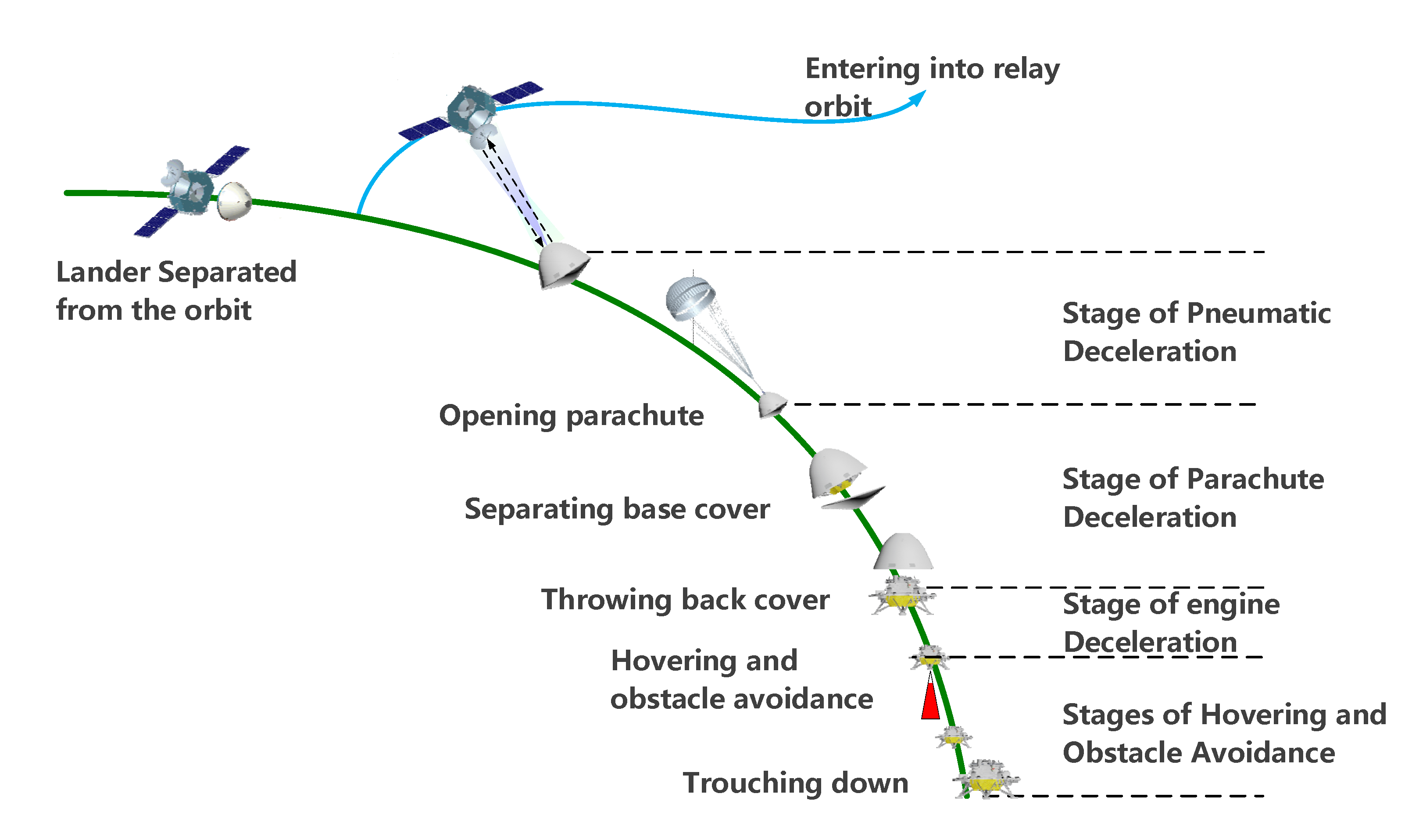
2.1. Data

Detailed observation and investigation of preselected landing areas are essential for the landing planning. The MoRIC, used for large scale imaging, has an image size of 4096 pixels × 3072 pixels and a resolution of over 100 m at the 400 km orbit [4]. The HiRIC onboard the Tianwen-1 orbiter operates in a linear sweep mode to obtain panchromatic optical images of the Martian surface with a resolution of over 2.5 m in normal areas and 0.5 m in key areas [4]. Since the sweep coverage width of HiRIC is about 9 km at the height of 265 km, multiple sweep orbital images of two preselected landing areas, located in the Chryse Planitia plain, the Isidis Planitia, and partly in Utopia Planitia, were captured, respectively [4,6]. A Digital Elevation Model (DEM) and a DOM of the landing area were produced and provided by Key Laboratory of Lunar and Deep Space Exploration, National Astronomical Observatories, and the Chinese Academy of Sciences. The DOM and DEM, having a resolution of 0.7 m/pixel and 3.5 m/pixel, respectively, are used as the base map for visual localization of the lander. By comparison, these mapping products have a good positional consistency with existing Mars maps, such as the global mosaic (5 m/pixel) of Context Camera (CTX) images [21] and the Mars MGS HRSC MOLA Blend DEM Global (200 m grid spacing) [22], which used MDIM2.1 reference frame tied to IAU/IAG 2000 Mars coordinate system [23,24]. In most parts of landing area, the relative shift of the HiRIC DOM is within one pixel of the CTX DOM.
The descent pair cameras, having a field of view (FOV) of 58° and an image size of 2048 pixels × 2048 pixels, are deployed for imaging landing area in EDL phase. One descent camera of the pair is mounted closely at the bottom edge of lander platform and the other one is mounted diagonally as the backup instrument. The first received single descent image, captured at a height of about 80 m estimated by the lander’s GNC system, has a very limited coverage area and a much higher ground resolution compared to the orbiter image, which led to great difficulties in image matching directly to conduct localization. Other descent images were arranged to be sent back to the ground control station completely through the relay of the orbiter 10 days after the first descent image downlinked.
The NaTeCam, a pair of stereo cameras installed on the camera mast of the Zhurong rover, is used to conduct panoramic imaging of the Martian surface in horizontal and vertical directions with the rotations of yaw and pitch drivers. The parameters of NaTeCam are listed in Table 1. During the mission, the stereo images of NaTeCam are regularly captured for topographic and geological analysis of the roving areas. In the mission, the two NaTeCam image collections that were received first were captured with a 360° yaw rotation and two pitch angles of −30° and −5° when the rover was atop the lander.

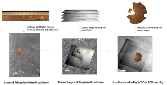
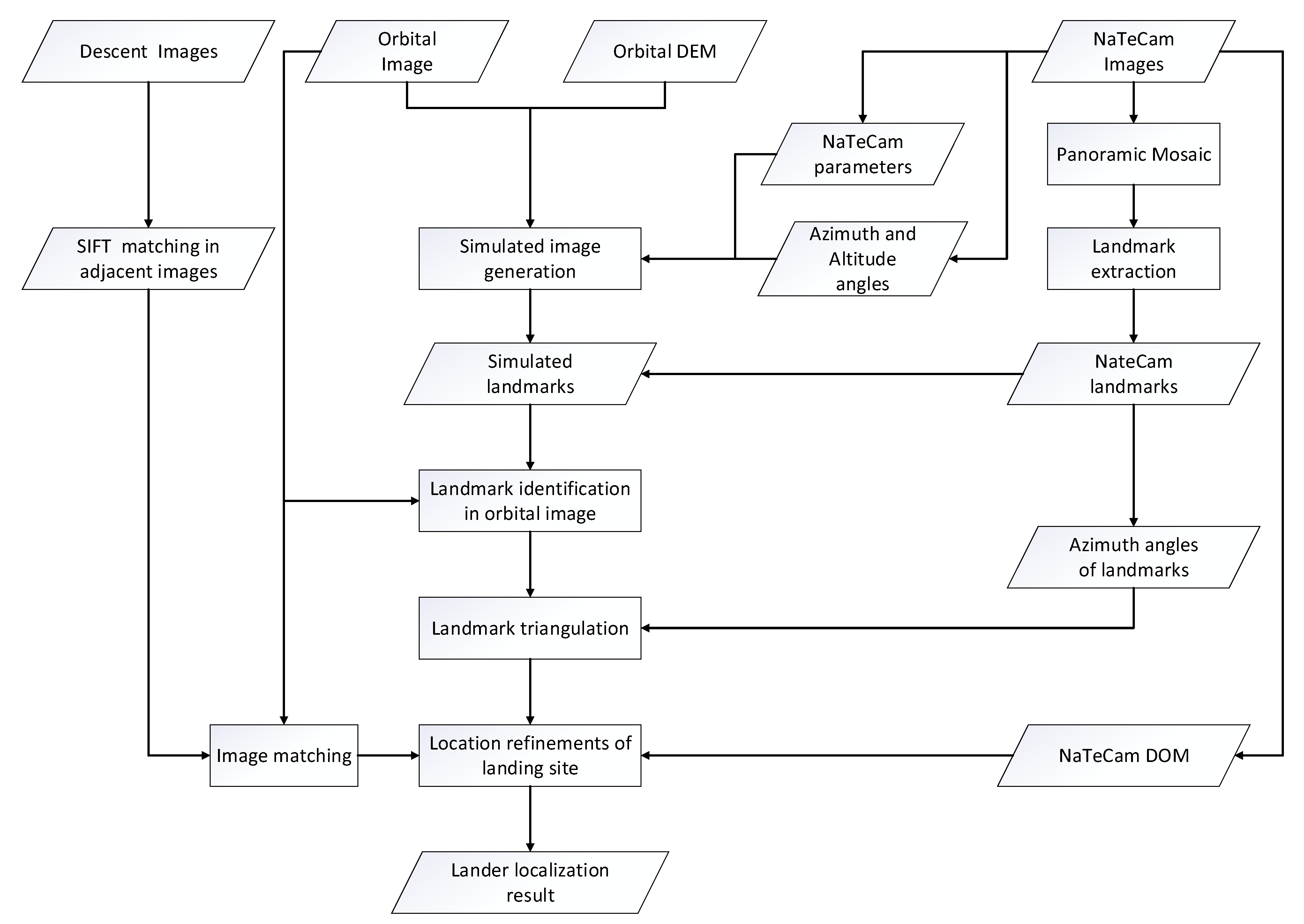
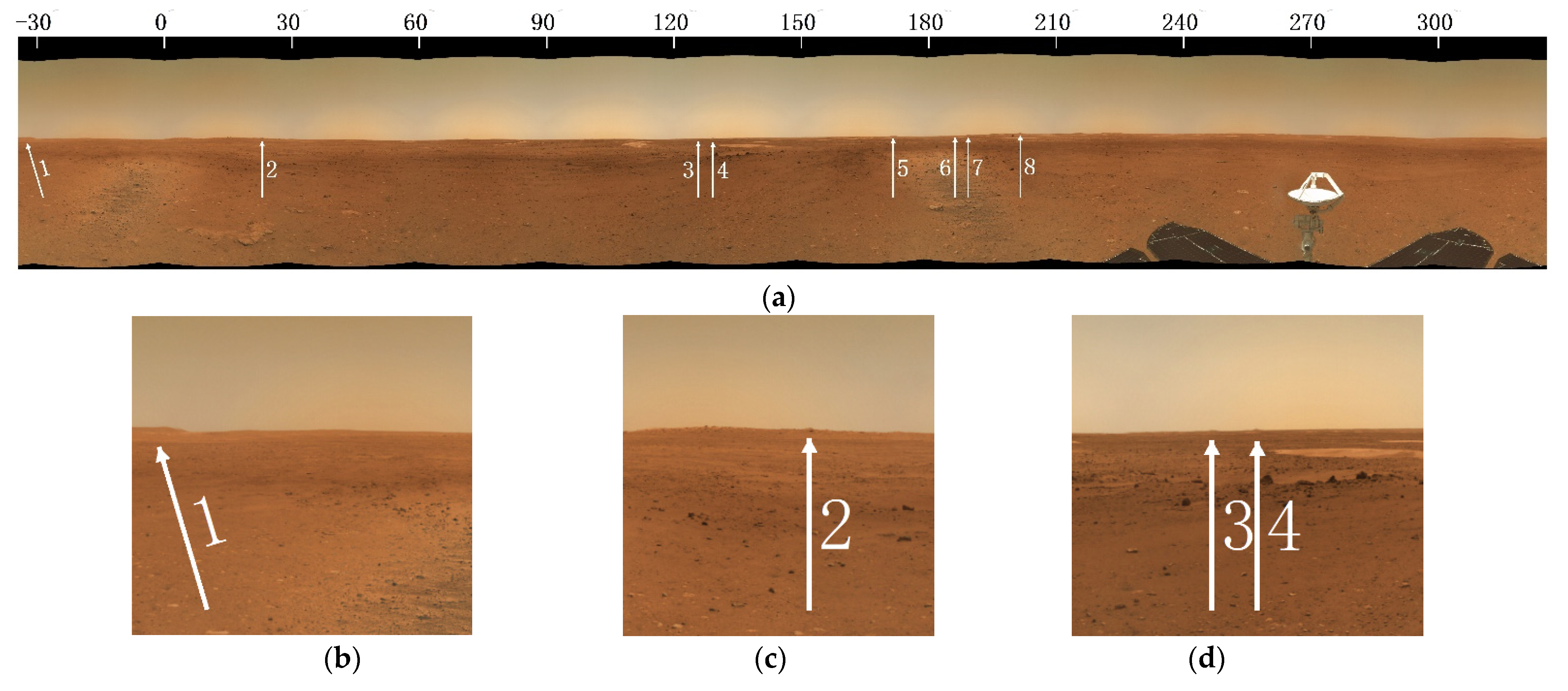
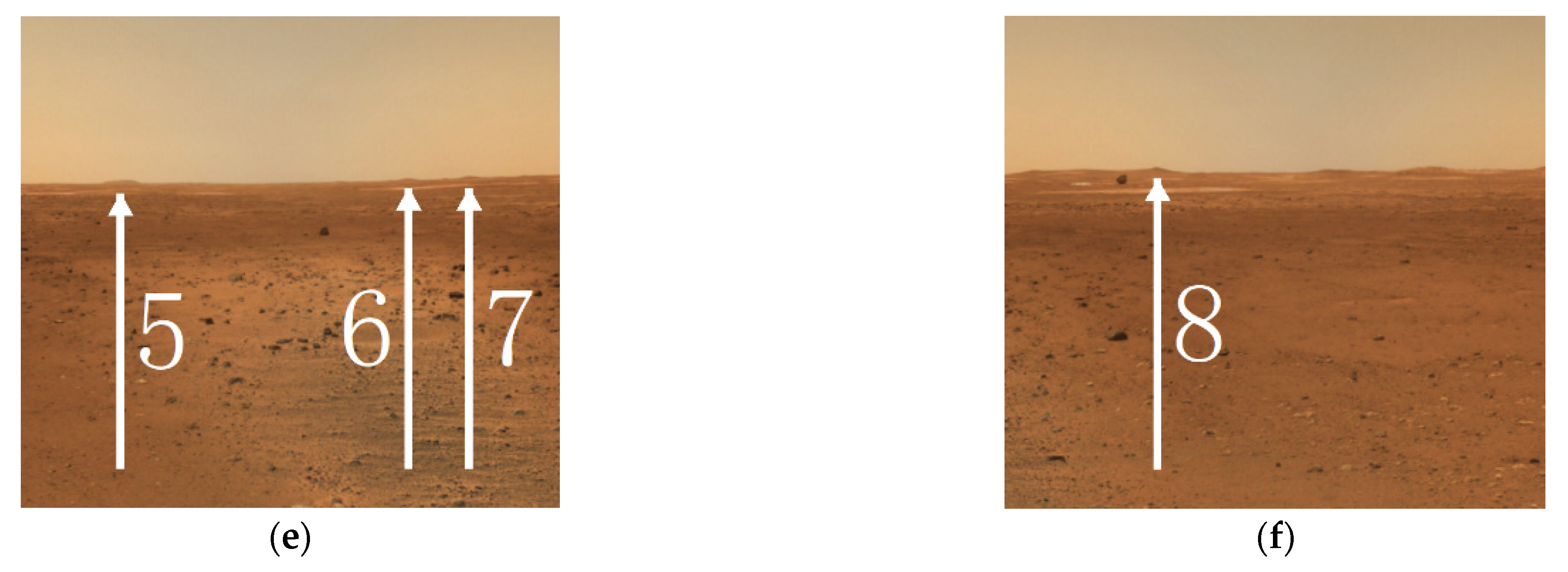
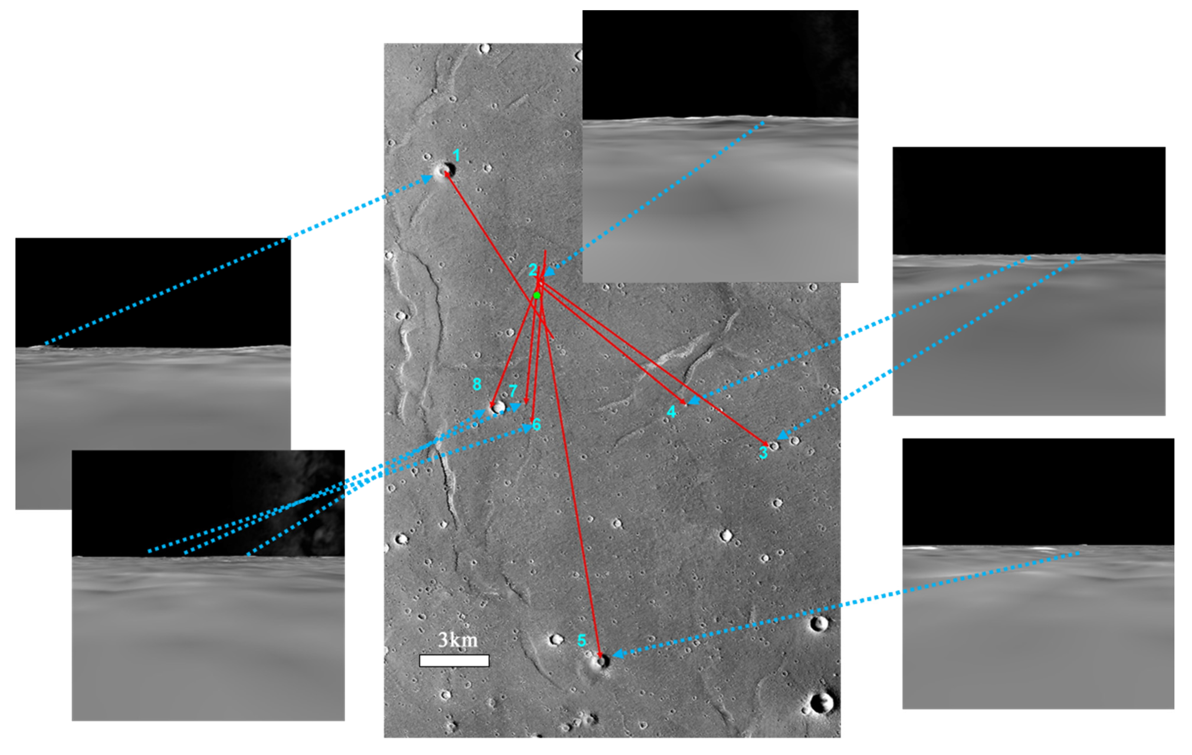
2.2. Initial Localization Based on Landmark Triangulation

Some geomorphic landmarks, such as mountain peaks, crater rims and so on, can be observed on the horizon of the panoramic NaTeCam images. Once the azimuth angles of the landmarks are measured in the NaTeCam imagery, the lander position can be determined by using landmark triangulation-based on the locations of the landmarks in the orbital base map.
To perform the landmark triangulation-based localization, we applied the cylindrical stitching method to the 12 pairs of NaTeCam images and generated a color panorama for landmark selection. Feature extraction and matching among the NaTeCam images were applied with the Scale-Invariant Feature Transform (SIFT) [25]. The transformation parameters of the projected image, including focus length, translation and rotation, were estimated based on the homographic transformation model. Finally, all images were projected into a pseudo cylindrical surface to generate the mosaic image. Before stitching, image enhancement and simple radiometric correction were applied for better performances in image matching and visualization. Figure 3 shows the SIFT matching results between adjacent NaTeCam images, which were enhanced and radiometrically corrected based on original acquired NaTeCam images.
In the panorama, the peaks and discontinues of skyline were considered as the candidate landmarks to be identified and matched in the orbital DOM manually. However, due to great differences in observation directions, it is very challenging to directly determine the corresponding landmarks between the orbital DOM and NaTeCam panorama. An image simulation system based on the orbital DEM and DOM was introduced to generate simulated NaTeCam images at multiple view angles, which is shown in Figure 4. By employing the multiple simulated images of one azimuth angles, the corresponding landmarks were effectively identified and verified manually.
To obtain the landmark azimuth angles with respect to the lander, the image points of identified landmarks in panorama were converted to the points in the original NaTeCam images with the transformation parameters of image stitching. The exterior orientation parameters (EOPs) of each NaTeCam image in the local landing site coordinate system were obtained with the rover orientation and 3 joint rotations of rover mast. By combining the image EOPs and image coordinates of landmarks, the landmark azimuth angles can be calculated based on the collinearity equation.
Based on the least square principle, the lander position can be estimated by the residual error minimization of all landmark azimuth angles, which is expressed as [26]:
P ^ = a r g m i n i = 1 n f P ( P L i ) A i
where n is the number of landmarks; P L i is the 2D position of ith landmark in the orthographic coordinate system centered at the landing location from lander’s GNC; A i is the azimuth angle of ith landmark from the measurements of NaTeCam images; f P ( P L i ) is the azimuth estimation function, which is represented as:
f P ( P L i ) = { a t a n 2 [ ( X L i X ) , ( Y L i Y ) ] , i f ( X L i X ) 0 360 + a t a n 2 [ ( X L i X ) , ( Y L i Y ) ] ,   i f   ( X L i X ) < 0
where atan2 is the inverse tangent function with a range of (−180, 180]; P = [ X Y ] T is   the   lander   location ; P L i = [ X L i Y L i ] T   is   the   location   of   landmark   i . By using the Taylor series expansion method, Formula (1) can be converted to the linearized equation system to solve the landing position iteratively. However, the uncertainties in the EOPs of NaTeCam images may bring about localization errors. The obtained initial location should be refined with the lately received sequential descent images.

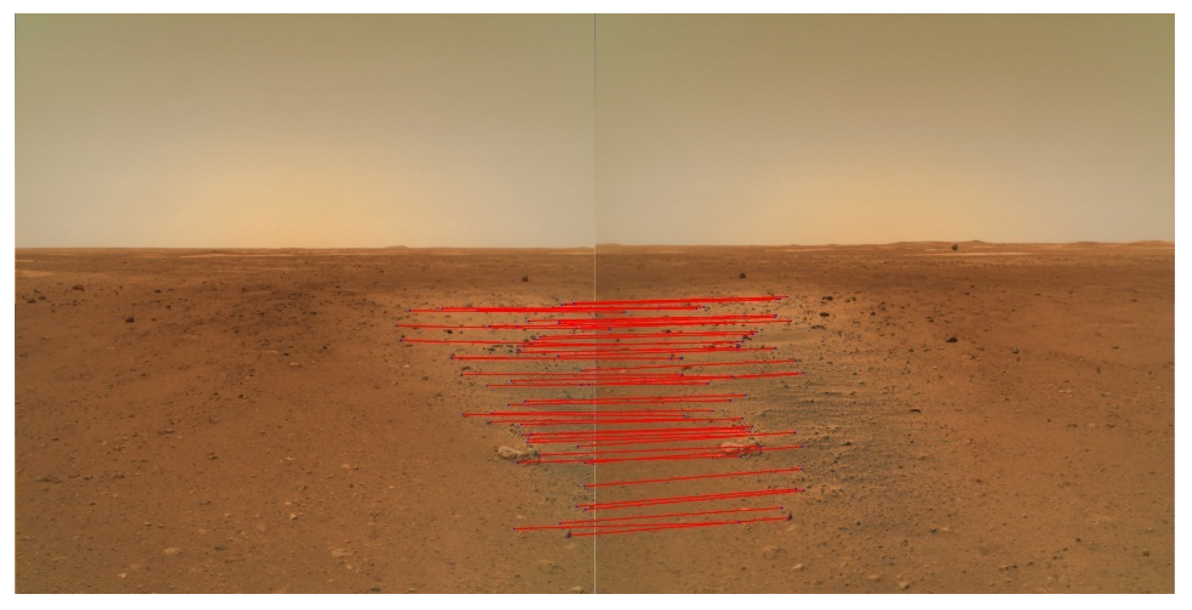
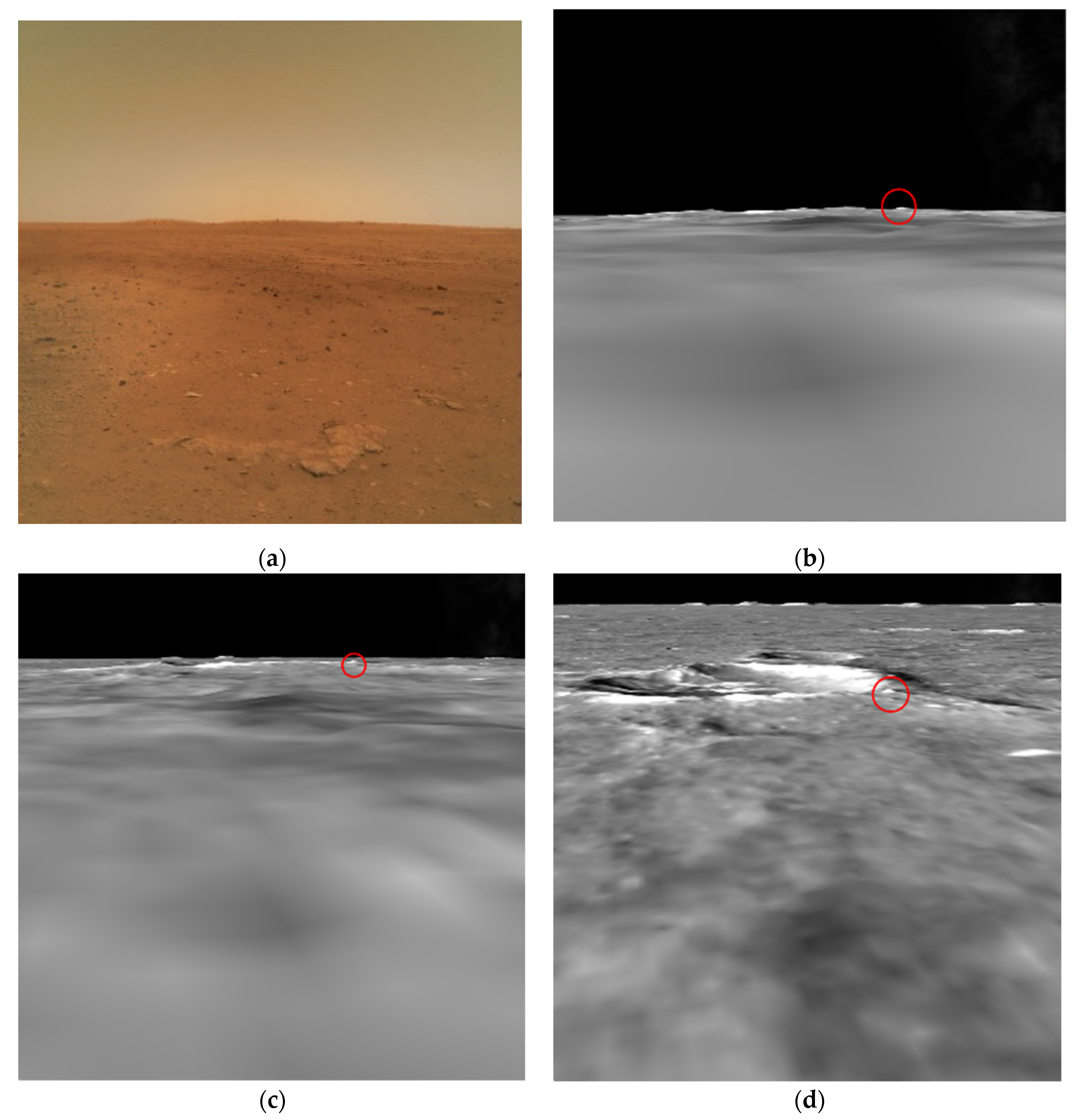
2.3. Refined Localization Based on Image Matching

To improve the localization accuracy, the image matching based localization method was applied with descent images to refine the localization result of landmark triangulation. Among the descent images without plume affects, the center of the descent image captured at the lowest height was traditionally considered as the landing point. By the SIFT matching method, the descent images were matched to obtain the geometric relationship between adjacent images, which was used for the landing point tracking in each descent image. Guided by the localization result of landmark triangulation, the descent images were matched with the orbital DOM to track the landing point down to the orbital DOM.
Due to the offset between the descent camera position and the center of the lander, and possible slanting descent, the lander location determined by the center of the used lowest descent image may not be accurate enough. In order to obtain the accurate lander location on the descent image, the NaTeCam DOM was applied to the image matching with the lowest descent image. Based on the matched points, we tracked the land location in the lowest descent and determined the accurate landing location in the orbital DOM.

3. Results

As is shown in Figure 5, the 12 left NaTeCam images, captured atop the landing platform with a pitch angle of −5°, were received at 14:00 pm, 22 May. These images were used to generate the 360° panorama with image stitching, from which the candidate landmarks were also selected.
The image coordinates of landmarks in the original NaTeCam images were obtained with the stitching transformation parameters. Each azimuth angle of a landmark was also calculated with the EOPs of NaTeCam images based on the collinearity equation. Assisted by the verification of simulated images, the corresponding landmarks in the orbital DOM were identified to obtain the geographic coordinates of landmarks. By employing the landmark triangulation method described in Section 2.2, the landing point position was determined to be (25.07°N, 109.93°E). Figure 6 shows the results of landmark identification and lander localization with the simulated and original NaTeCam images. By minimizing the errors of the landmark azimuth angles drawn in red lines under the least squares principle, the initial localization result based on landmark triangulation, shown as the green point, was accomplished on 25 May 2021.
With the guidance of the localization result from landmark triangulation method, we chose four descent images, downlinked subsequently at 17:30 pm, 29 May, to conduct the image matching based localization. SIFT was applied to image matching in adjacent descent frames. With matching results, the landing point approximately centered at the image captured at the lowest altitude was tracked among descent images. Then, the matching between the descent images and orbital DOM achieved the global landing location determination. Furthermore, to decrease the localization error caused by the slight offset between the descent camera and the center of the lander, the NaTeCam DOM, produced by the images captured with a pitch angle of −30°, was employed to refine the landing position from the matching of the lowest descent image and the base map. As the final result, the landing location was determined at (25.066°N, 109.925°E). Figure 7 shows the results of image matching based localization. This final localization result was accomplished on 29 May 2021.
After landing, the Tianwen-1 orbiter conducted repeat observations of the landing area, and in the HiRIC image captured on 2 June 2021 the lander and Zhurong rover are visible [27]. By comparison, the accuracy of our visual localization result is within a pixel of the orbital image. Figure 8 shows the verification of the visual localization result with the newly acquired HiRIC image in which the lander and Zhurong rover are visible. On 6 June 2021, the HiRISE onboard MRO also acquired a high resolution image of the Tianwen-1 landing area [28]. Our lander localization result can be also verified in the HiRISE image.
The uncertainty of the localization results mainly depended on the positioning precision of the HiRIC DOM in cartographic frame and the image matching based localization errors relative to the HiRIC DOM. The HiRIC DOM is highly consistent with the CTX DOM registered with Mars Orbiter Laser Altimeter (MOLA) data, which has a positioning accuracy of about 100 m in the IAU/IAG Mars 2000 coordinate system [29]. Before sequential descent images downlinked, the initial localization result was derived from landmark triangulation. The selected landmarks were identified on the HiRIC DOM and NaTeCam images manually. The landmark azimuth angles, used to intersect the lander location, were the main error sources of the localization result. The orientation errors of NaTeCam images, caused by the uncertainties of mast control and rover altitude measurements, brought about the azimuth angle measurement errors (typically 2 degrees) and the location error of about 38 m compared to the final determined location. Guided by the triangulation-based localization result, the latter downlinked descent images were directly matched with the orbital DOM. After refined by matching with the NaTeCam DOM, the error of lander location was within one pixel of the HiRIC DOM (0.7 m/pixel), through the verification with the new orbital image with the lander and Zhurong rover visible. In all, the uncertainties of the proposed lander localization results in the Mars body-fixed coordinate system were estimated about 100 m.

4. Conclusions

The accurate localization of the Tianwen-1 lander is critical to the subsequent mission operations, e.g., data transmission between the lander and the orbiter, separation of the rover from the lander platform, and rover path planning on Martian surface. To achieve the accurate landing location in a timely manner, the remote landmarks found in the earliest received NaTeCam images were identified in the orbital DOM of the landing area to conduct the landmark triangulation-based lander localization. Then, guided by the initial localization result, we employed the sequential descent images received later to perform image matching among adjacent descent frames and with the orbital DOM and obtained the refined lander localization result. At the end, the generated NaTeCam DOM was matched with the descent image to determine the final accurate location of the lander, which is (25.066°N, 109.925°E) ± (0.002°N, 0.002°E). The localization result has been used to support various mission operations. The accuracy of the lander localization has been verified to be within a pixel of the orbital DOM compared to the newly acquired orbital image with the visibility of the lander. The accurate lander location will also contribute to synergistic scientific analysis of the landing site using multi-source data from multiple missions.

Author Contributions

Conceptualization, W.W., K.D. and Z.L.; methodology, W.W., K.D. and Z.L.; software, W.W., K.D., Z.L., B.L., Y.W., M.P., Z.B., L.Y. (Lejia Ye), R.W., L.Y. (Li Yin), M.Y. and K.S.; validation, W.W., T.Y., K.D., J.W., Z.L., L.L., X.H., Z.Z., H.Z., H.L. and S.B.; investigation, W.W., K.D., Z.L., B.L., Y.W. and M.P.; writing—original draft preparation, W.W., K.D., Z.L. and J.W.; writing—review and editing, W.W., T.Y., K.D., J.W. and Z.L. All authors have read and agreed to the published version of the manuscript.

Funding

This work was supported by the Strategic Priority Research Program of the Chinese Academy of Sciences (grant no. XDB41000000) and the National Natural Science Foundation of China (grant no. s 41771490 and 41771488).

Acknowledgments

The Tiawen-1 mission was carried out by the Chinese Planetary Exploration Program. We thank the Lunar and Deep Space Exploration Science Applications Center of the National Astronomical Observatories for providing the HiRIC DOM and DEM.

Conflicts of Interest

The authors declare no conflict of interest.

References

  1. China Daily. China’s Mars Mission Launched in Hainan. Available online: https://global.chinadaily.com.cn/a/202007/24/WS5f1a3859a31083481725bc81.html (accessed on 2 June 2021).
  2. China Daily. Tianwen 1 is 1st Chinese Spacecraft to Reach Mars. Available online: https://www.chinadaily.com.cn/a/202102/11/WS602473eda31024ad0baa8adc.html (accessed on 3 June 2021).
  3. China Daily. Mars Probe Enters Parking Orbit. Available online: https://www.chinadaily.com.cn/a/202102/25/WS6036f89ca31024ad0baaae59.html (accessed on 3 June 2021).
  4. Zou, Y.; Zhu, Y.; Bai, Y.; Wang, L.; Jia, Y.; Shen, W.; Fan, Y.; Liu, Y.; Wang, C.; Zhang, A.; et al. Scientific objectives and payloads of Tianwen-1, China’s first Mars exploration mission. Adv. Space Res. 2020, 67, 812–823. [Google Scholar] [CrossRef]
  5. Yu, G.; Liu, E.; Liu, G.; Zhou, L.; Zeng, J.Z.; Chen, Y.P.; Zhou, X.D.; Zhao, R.J.; Zhu, S.Y. Moderate Resolution Imaging Camera (MoRIC) of China’s First Mars Mission Tianwen-1. Earth Planet. Phys. 2020, 4, 364–370. [Google Scholar]
  6. Li, C.; Zhang, R.; Yu, D.; Dong, G.; Liu, J.; Geng, Y.; Sun, Z.; Yan, W.; Ren, X.; Su, Y.; et al. China’s Mars Exploration Mission and Science Investigation. Space Sci. Rev. 2021, 217, 1–24. [Google Scholar] [CrossRef]
  7. Meng, Q.; Wang, D.; Wang, X.; Li, W.; Yang, X.; Yan, D.; Li, Y.; Cao, Z.; Ji, Q.; Sun, T.; et al. High Resolution Imaging Camera (HiRIC) on China’s First Mars Exploration Tianwen-1 Mission. Space Sci. Rev. 2021, 217, 1–29. [Google Scholar] [CrossRef]
  8. Website of China National Space Administration. Probe Makes Historic Landing on Mars. Available online: http://www.cnsa.gov.cn/english/n6465652/n6465653/c6812005/content.html (accessed on 20 May 2021).
  9. Xinhua Net. 4th LD-Writethru-Xinhua Headlines: China Succeeds in First Mars Landing. Available online: http://www.xinhuanet.com/english/2021-05/15/c_139947906.htm (accessed on 20 May 2021).
  10. Xinhua Net. China’s First Mars Rover Starts Exploring Red Planet. Available online: http://www.xinhuanet.com/english/2021-05/22/c_139963090.htm (accessed on 4 June 2021).
  11. Li, R.; Squyres, S.W.; Arvidson, R.E.; Archinal, B.A.; Bell, J.; Cheng, Y.; Crumpler, L.; Marais, D.J.D.; Di, K.; Ely, T.A.; et al. Initial Results of Rover Localization and Topographic Mapping for the 2003 Mars Exploration Rover Mission. Photogramm. Eng. Remote. Sens. 2005, 71, 1129–1142. [Google Scholar] [CrossRef] [Green Version]
  12. Wan, W.; Liu, Z.; Liu, Y.; Di, K.; Zhou, J.; Wang, B.; Liu, C.; Wang, J. Descent Image Matching Based Position Evaluation for Chang’e-3 Landing Point. Spacecr. Eng. 2014, 23, 5–12. [Google Scholar]
  13. Di, K.; Liu, Z.; Liu, B.; Wan, W.; Peng, M.; Wang, Y.; Gou, S.; Yue, Z.; Xin, X.; Jia, M. Chang’e-4 lander localization based on multi-source data. J. Remote Sens. 2019, 23, 177–180. [Google Scholar]
  14. Wang, J.; Zhang, Y.; Di, K.; Chen, M.; Duan, J.; Kong, J.; Xie, J.; Liu, Z.; Wan, W.; Rong, Z.; et al. Localization of the Chang’e-5 Lander Using Radio-Tracking and Image-Based Methods. Remote Sens. 2021, 13, 590. [Google Scholar] [CrossRef]
  15. Li, R.; Di, K.; Matthies, L.H.; Folkner, W.M.; Arvidson, R.E.; Archinal, B.A. Rover Localization and Landing-Site Mapping Technology for the 2003 Mars Exploration Rover Mission. Photogramm. Eng. Remote. Sens. 2004, 70, 77–90. [Google Scholar] [CrossRef] [Green Version]
  16. Di, K.; Liu, Z.; Yue, Z. Mars rover localization based on feature matching between ground and orbital imagery. Photogramm. Eng. Remote Sens. 2011, 77, 781–791. [Google Scholar] [CrossRef]
  17. Li, C.; Liu, J.; Ren, X.; Zuo, W.; Tan, X.; Wen, W.; Li, H.; Mu, L.; Su, Y.; Zhang, H.; et al. The Chang’e 3 mission overview. Space Sci. Rev. 2015, 190, 85–101. [Google Scholar] [CrossRef]
  18. Liu, Z.; Di, K.; Peng, M.; Wan, W.; Liu, B.; Li, L.; Yu, T.; Wang, B.; Zhou, J.; Chen, H. High precision landing site mapping and rover localization for Chang’e-3 mission. Sci. China Ser. G Phys. Mech. Astron. 2015, 58, 1–11. [Google Scholar] [CrossRef]
  19. Liu, Z.; Di, K.; Li, J.; Xie, J.; Cui, X.; Xi, L.; Wan, W.; Peng, M.; Liu, B.; Wang, Y.; et al. Landing site topographic mapping and rover localization for Chang’e-4 mission. Sci. China Inf. Sci. 2020, 63, 1–12. [Google Scholar] [CrossRef] [Green Version]
  20. Liang, X.; Chen, W.; Cao, Z.; Wu, F.; Lyu, W.; Song, Y.; Li, D.; Yu, C.; Zhang, L.; Wang, L. The Navigation and Terrain Cameras on the Tianwen-1 Mars Rover. Space Sci. Rev. 2021, 217, 1–20. [Google Scholar] [CrossRef]
  21. Dickson, J.L.; Kerber, L.A.; Fassett, C.I.; Ehlmann, B.L. A global, blended CTX mosaic of Mars with vectorized seam mapping: A new mosaicking pipeline using principles of non-destructive image editing. In Proceedings of the 49th Lunar and Planetary Science Conference, The Woodlands, TX, USA, 19–23 March 2018. [Google Scholar]
  22. Fergason, R.L.; Hare, T.M.; Laura, J. HRSC and MOLA Blended Digital Elevation Model at 200 m. 2018. Available online: https://astrogeology.usgs.gov/search/map/Mars/Topography/HRSC_MOLA_Blend/Mars_HRSC_MOLA_BlendDEM_Global_200mp_v2 (accessed on 3 June 2021).
  23. Dickson, J.L.; Ehlmann, B.L. Image-to-Image Registration for a CTX Mosaic of Mars at the Global Scale: Estimations of Offset in MRO CTX Image Pointing. In Proceedings of the 52nd Lunar and Planetary Science Conference (LPSC 2021), The Woodlands, TX, USA, 15–19 March 2021. [Google Scholar]
  24. Archinal, B.A.; Kirk, R.L.; Duxbury, T.C.; Lee, E.M. Mars digital image model 2.1 control network. In Proceedings of the 34th Lunar and Planetary Science Conference (LPSC 2003), League City, TX, USA, 17–21 March 2003; Lunar and Planetary Institute: Houston, TX, USA, 2003. [Google Scholar]
  25. Lowe, D. Distinctive image features from scale invariant keypoints. Int. J. Comput. Vis. 2004, 60, 91–110. [Google Scholar] [CrossRef]
  26. Thornton-Smith, G.J. Solution of position lines by the method of least squares. Aust. Surv. 1945, 10, 179–184. [Google Scholar] [CrossRef]
  27. Website of China National Space Administration. New Images of Mars Taken by the Tianwen-1 Probe Have Been Released. Available online: http://www.cnsa.gov.cn/english/n6465652/n6465653/c6812112/content.html (accessed on 8 June 2021).
  28. Website of Nature. Flurry of Photos Capture China’s Zhurong Rover on Surface of Mars. Available online: https://www.nature.com/articles/d41586-021-01588-6 (accessed on 12 June 2021).
  29. Simith, D.E.; Zuber, M.T.; Frey, H.V.; Garvin, J.B.; Head, J.W.; Muhleman, D.O.; Pettengill, G.H.; Phillips, R.J.; Solomon, S.C.; Zwally, H.J. Mars orbiter laser altimeter: Experiment summary after the first year of global mapping of Mars. J. Geophys. Res. 2001, 106, 23689–23722. [Google Scholar] [CrossRef]
Figure 1. Diagram of the entry, descent and landing of Tianwen-1.
Remotesensing 13 03439 g001
Figure 2. The workflow of the proposed method.
Remotesensing 13 03439 g002
Figure 3. The SIFT matching result between adjacent NaTeCam images. The red lines link the corresponding matched points between adjacent NaTeCam images.
Remotesensing 13 03439 g003
Figure 4. The original and simulated NaTeCam images: (a) is the original NaTeCam image received on 22 May, 14:00 (UTC +8); (b) is the simulated image generated from the same azimuth and altitude angle as (a) based on the orbital DEM and DOM; (c) and (d) are the simulated images at incremental heights based on the orbital DEM and DOM. The red circle is a landmark on the Martian surface.
Remotesensing 13 03439 g004
Figure 5. The 360° panorama of NaTeCam images with extracted landmarks. The white arrows point to the landmarks. (a) shows the eight landmarks extracted in NaTeCam panorama; (bf) show the regional enlarged images of landmarks.
Remotesensing 13 03439 g005aRemotesensing 13 03439 g005b
Figure 6. Initial localization result based on the landmark triangulation method. The central image is the HiRIC DOM, the others are the simulated images; the green point is the lander location; the red lines are the azimuth lines of the landmarks; the blue number is the index of landmark extracted in NaTeCam panorama in Figure 5.
Remotesensing 13 03439 g006
Figure 7. The localization results based on image matching methods: (a) shows the results of image matching among the sequential descent images and the HiRIC DOM; (b) shows the triangulation, descent image matching and NaTeCam DOM matching based localization results, which are represented as the green, yellow and red points.
Remotesensing 13 03439 g007
Figure 8. Verification of the localization result with the newly acquired orbital image [21]: (a) is the visual localization result; (b) is the released orbital image with the visibility of the lander and Zhurong rover.
Remotesensing 13 03439 g008
Table 1. Parameters of NaTeCam [20].
ItemNaTeCam
Frame (pixels × pixels)2048 × 2048
Pixel size (mm)0.0055
Focal length (mm)13.1
Baseline length (m)0.27
Publisher’s Note: MDPI stays neutral with regard to jurisdictional claims in published maps and institutional affiliations.

