Abstract
After a major earthquake in a dense urban area, the spatial distribution of heavily damaged buildings is indicative of the impact of the event on public safety. Timely assessment of the locations of severely damaged buildings and their damage morphologies using remote sensing approaches is critical for search and rescue actions. Detection of damaged buildings that did not suffer collapse can be highly challenging from aerial or satellite optical imagery, especially those structures with height-reduction or inclination damage and apparently intact roofs. A key information cue can be provided by a comparison of predicted building shadows based on pre-event building models with shadow estimates extracted from post-event imagery. This paper addresses the detection of damaged buildings in dense urban areas using the information of building shadow changes based on shadow simulation, analysis, and image processing in order to improve real-time damage detection and analysis. A novel processing framework for the rapid detection of damaged buildings without collapse is presented, which includes (a) generation of building digital surface models (DSMs) from pre-event LiDAR data, (b) building shadow detection and extraction from imagery, (c) simulation of predicted building shadows utilizing building DSMs, and (d) detection and identification of shadow areas exhibiting significant pre- and post-event differences that can be attributed to building damage. The framework is demonstrated through two simulated case studies. The building damage types considered are those typically observed in earthquake events and include height-reduction, over-turn collapse, and inclination. Total collapse cases are not addressed as these are comparatively easy to be detected using simpler algorithms. Key issues are discussed including the attributes of essential information layers and sources of error influencing the accuracy of building damage detection.
1. Introduction
Major threats to public safety in many areas of the world involve earthquakes in urban areas that contain dense high-rise buildings and population. High casualties can arise as people are trapped in severely damaged, unstable standing buildings. Such buildings are also dangerous for rescue teams, particularly during the aftershocks, so timely assessment of their locations and conditions is crucial.
High-resolution imagery from aerial and satellite-based sensors can provide valuable timely building damage information over large areas of coverage after the earthquake event [1]. However, obtaining remotely and timely precise information about locations and conditions of damaged buildings is still challenging for real-time disaster response. Ideal data for detection of damaged buildings, but seldom available in practice, are pairs of pre- and post-disaster digital surface models (DSMs) derived from aerial light detection and ranging (LiDAR) data with high resolution in combination with high-resolution multi-spectral imagery. The paired LiDAR-based DSMs can provide precisely the three-dimensional changes in the building shape due to damages. Such datasets can provide the most accurate information about the geometric structural conditions of affected buildings [2,3]. Pairs of pre- and post-disaster DSMs, derived from stereo optical satellite images, have previously been exploited in this application [4,5,6]. The post-event data from high-resolution multispectral and LiDAR sensors have been used in several tests of damaged building detection [7,8,9]. In addition, a number of mature scene interpretation techniques can be used to enhance building assessments. Shadow information extracted from high-resolution optical imagery can capture additional attributes of building geometry [10]. For example, building shadow information extracted from single high-resolution optical images has been used for the detection of buildings [11,12] and estimation of building height [13,14,15,16,17,18,19,20]. Change detection techniques at pixel and object levels have been used to detect buildings exhibiting significant radiometric, texture, and/or geometric differences between pre- and post-event image acquisitions [1,21,22,23,24]. It should be noted that the utilization of shadow changes is complicated by other factors that impact shadow appearance, namely, differences in solar viewing elevation and azimuth of the two images in question. On the other hand, the impacts of solar illumination geometry on shadows cast by a three-dimensional object are readily predicted. Tong et al. [25] generated theoretical three-dimensional building surface models for detecting locations of damaged buildings using building footprints and height information and then compared the simulated pre-disaster shadow areas based on the building surface model and the shadow information from the post-disaster imagery. Before shadow change detection based on the baseline building surface models can be used in practice, the sensitivity of shadow change to quantifying aspects of building damage should be assessed and analysed.
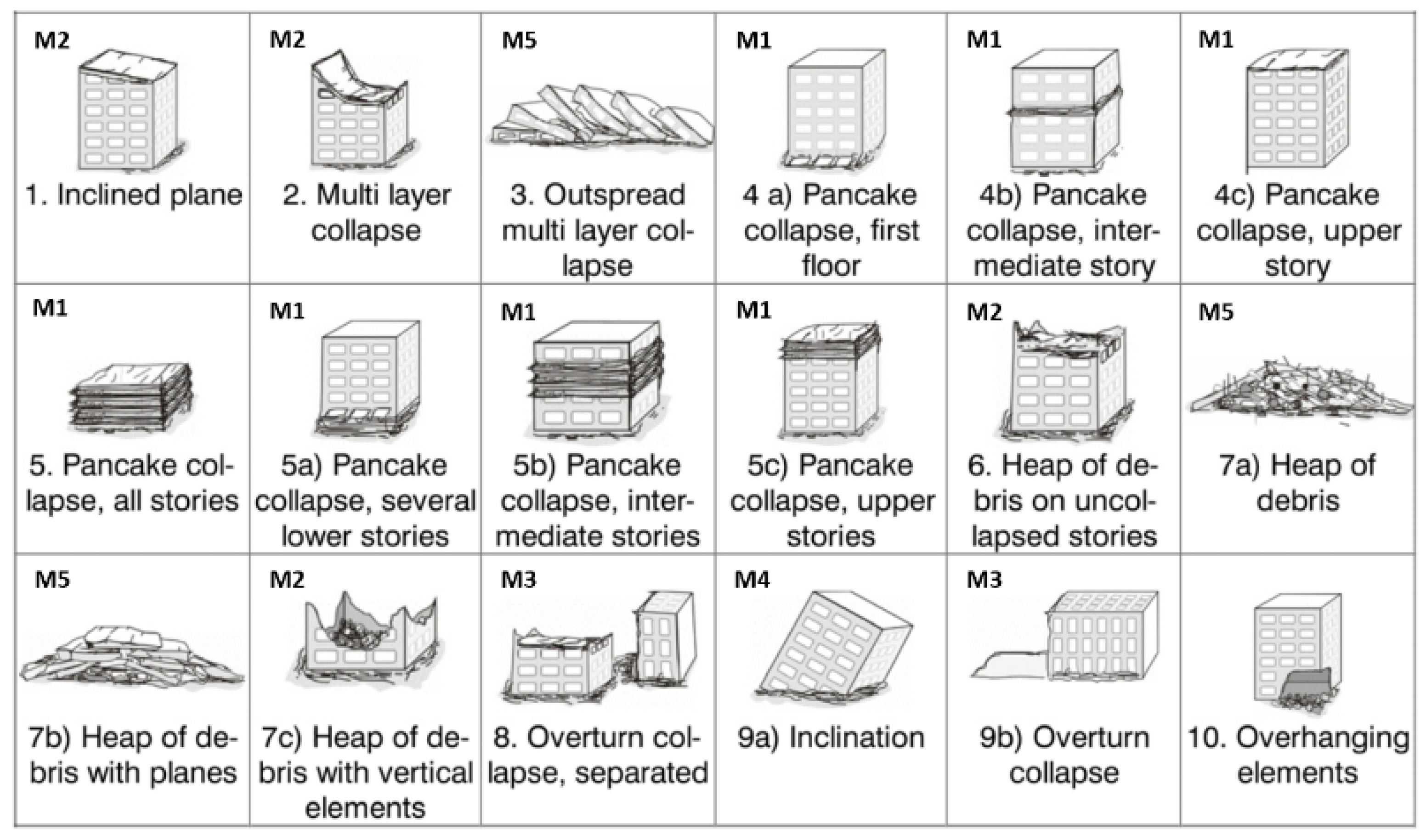
There are various morphologies of building damage associated with a major earthquake disaster. A categorization of building damage types has been developed by Schweier and Markus [26]. These common building damage occurrences were categorized into 18 types by ground field observations. Height-reduced building damage and inclination building damage are among these major damage types (Figure 1). Particularly in the case of height-reduced or inclination building damage [27] the damage can result from partial collapse or distortion of a building with an intact roof and limited surrounding rubble fields. In multispectral optical imagery from remote sensing sensors such as those onboard satellites or aircraft, height-reduced or inclination building damage is much more difficult to detect even with manual interpretation than more heavily damaged cases that include horizontal building shifts and/or reduction of structures to rubble, since there are fewer image radiometric and textural cues. On the other hand, with topological concepts (such as that in the work of Hermosilla et al. [28]), as building height and shape can be inferred from cast shadows, shadow comparison of pre- and post-event datasets provides an opportunity for detecting these types of building damage. A precise shadow change map can be helpful for real-time detection and analysis of building damage after a major earthquake [29].
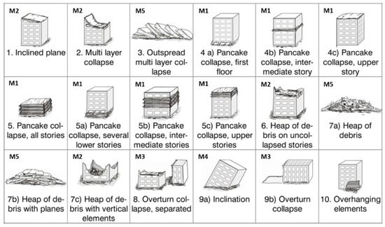
Figure 1.
Building damage models regrouped from the earthquake-induced building damage classification by Schweier and Markus [26] (Reprinted with permission from ref. [26]. Copyright 2004, Michael Markus).
The main objectives of this work are twofold; first, to develop a framework, based on remote sensing technologies, for the rapid detection of earthquake-induced building damage (without collapse) in dense urban areas encompassing high- and low-rise buildings and secondly, to assess the effectiveness and limitations of building damage detection based on shadow change information derived from baseline building DSMs and high-resolution optical imagery. In this work, a number of key issues are also addressed including (a) requisite information layers needed for accurate pre- and post-event shadow estimation, (b) factors of LiDAR-derived baseline building DSMs impacting the accuracy of building damage detection, and (c) limitations and errors associated with the employment of shadow change information for building damage detection.
2. Methodologies
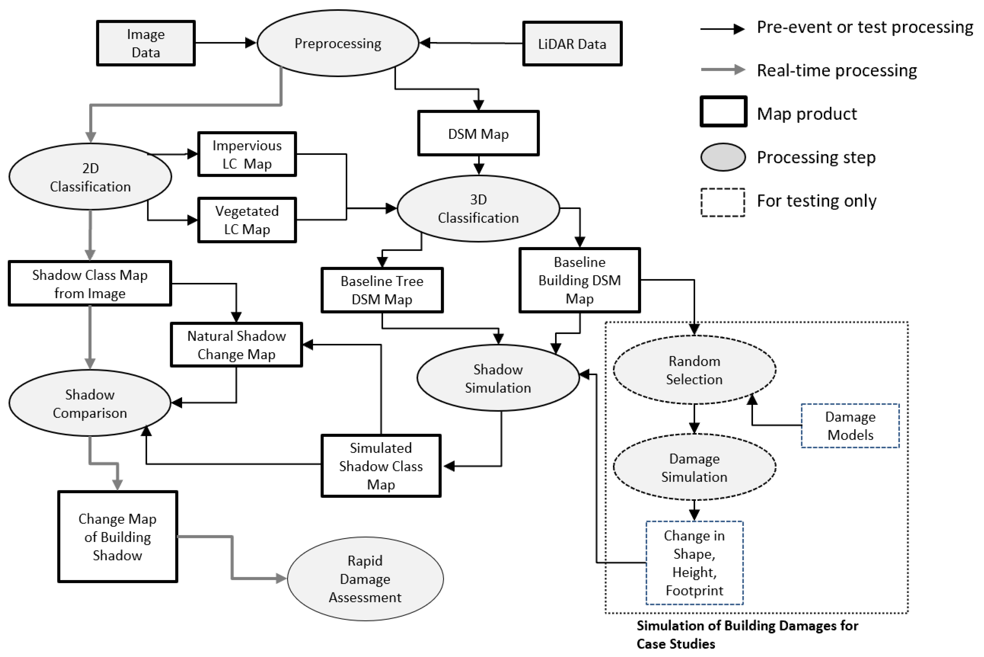
There are image processing and simulation methodologies involved in our processing framework. Figure 2 illustrates the proposed processing flow for damage assessment based on shadow analysis.
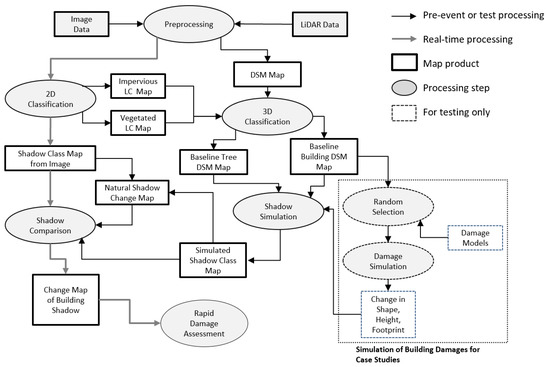
Figure 2.
Outline of the framework for rapid damaged building detection. In the figure, DSM: digital surface model; LiDAR: light detection and ranging; LC: land cover.
2.1. Generation of Baseline Building Digital Surface Models (DSMs)
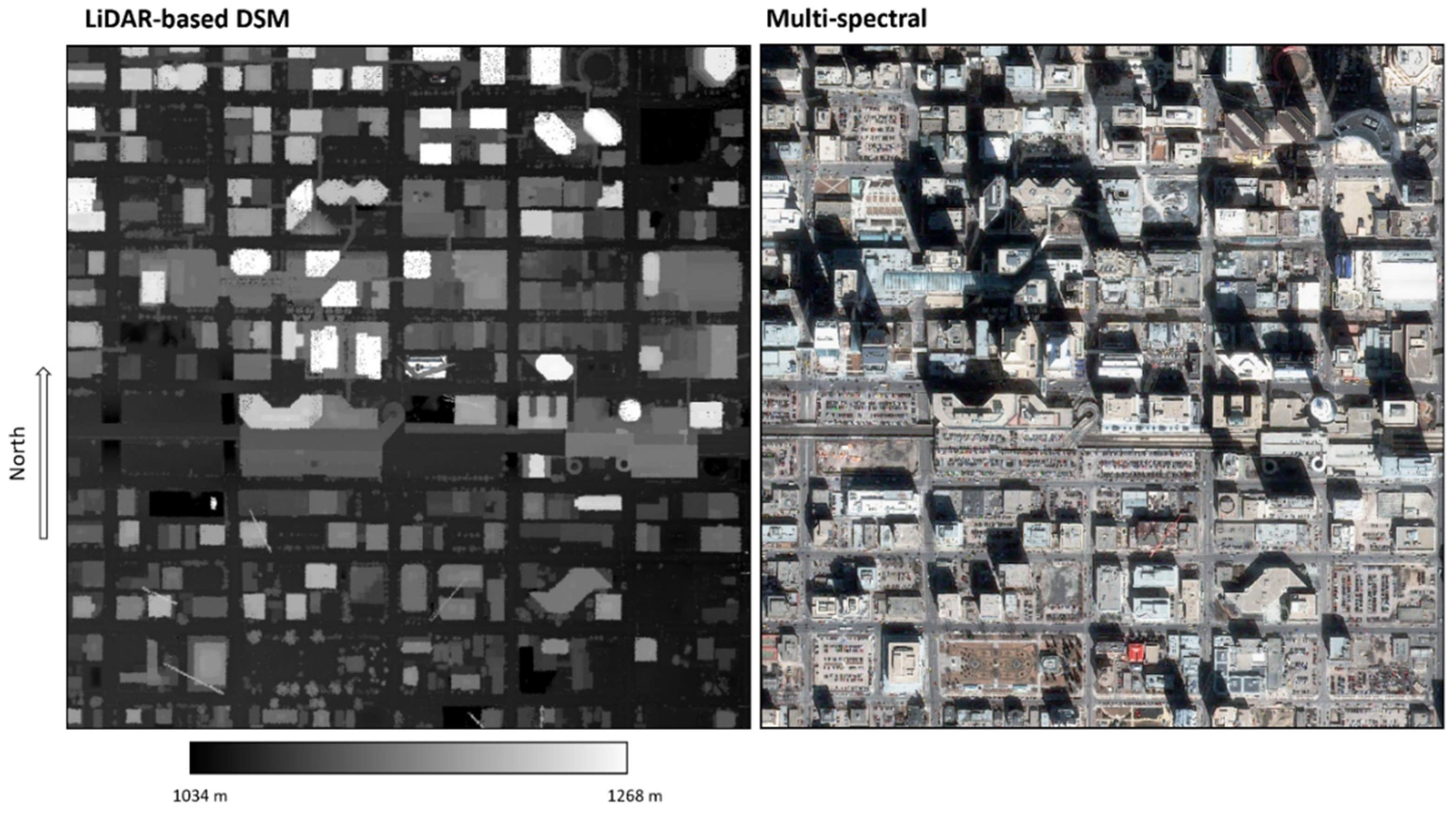
In this study, the DSMs of buildings provide a fundamental data source for investigating the shadow change behaviors and relationship between shadows and building damage; the DSM data include the pre-event ‘null hypothesis’ (i.e., no damage) set and post-event (i.e., with damage) sets. Two types of pre-event baseline DSM data have been used for the experiments and analyses described below. In the first case (Case A), an artificial DSM (1000 by 1000 pixels in extent) of synthetic buildings for testing was created. These buildings are rectangular in shape with flat roofs and have been assigned random characteristics of horizontal footprint size, building orientation, and building height. This DSM does not include other features such as trees, roads, etc., and its primary purpose is to evaluate shade sensitivities to various forms of damaged buildings. The second DSM case (Case B) comprises elevation information of an actual urban core area generated from airborne LiDAR data. Figure 3 illustrates the raw DSM map derived from LiDAR data as well as a Pleiades PAN-sharpened image used for this study. The LiDAR-based DSM image (shown in Figure 3 left; data provided by the Airborne Imaging Inc) in question covers a portion of the downtown area of Calgary, Canada. This study area is in the central business district of Calgary, which has a dense building distribution including a complex mix of high- and low-rise buildings with a large variation in building height and shapes. The raw DSM from LiDAR data, sampled on a 1 m grid (derived from a height cloud point density of 1.3 samples per m2), covers a 1 by 1 km site and was acquired on 15 August 2007. A portion of a Pleiades sensor image (shown in Figure 3 right), covering the Calgary DSM map, has also been used to generate the final version of the baseline Calgary DSM and for the evaluation of DSM-derived shadow information. This multi-spectral image acquired on 10 April 2014 has been pan-sharpened with a panchromatic band of spatial resolution 0.5 m.
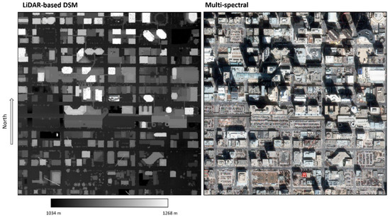
Figure 3.
Imagery data, raw DSM derived from LiDAR (left, scale in meter) and Pleiades multispectral image (right: shown in RGB), used for the Case B study. DSM: digital surface model; LiDAR: light detection and ranging.
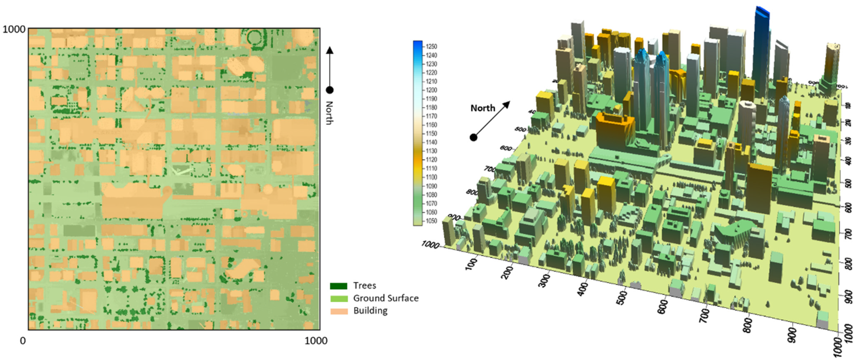
For the creation of a building class map and quality improvement of the raw DSM with noise, further pre-processing of the raw DSM from LiDAR is needed. The generation of a high-quality map of building DSMs involves a number of processing steps. First, trees have been identified to isolate building objects on the LIDAR and the Pleiades images. This has been accomplished first through a classification of the co-registered Pleiades multi-spectral image into vegetated and non-vegetated areas; then a tree class map was generated with the help of classifications of optical images and corresponding LiDAR height data. Further processing of three-dimensional building objects has resulted in improved delineation by using the building footprints and removing the noise on building tops. The final land cover classification map illustrating refined distribution of buildings and trees is shown in Figure 4 left, and the final DSM map for the study area, including the DSMs of buildings and tree canopies, is presented in a perspective view in Figure 4 right.

Figure 4.
The land cover map (left) and modified DSM map (right) for testing site of Case B. The scales are in meters.
2.2. Shadow Simulation
For buildings or trees (Case B in the LiDAR-based DSM map), the locations of shadow pixels are estimated from the equation below.
where X and Y are the pixel row and line coordinates of the shadow cast by a building or the tree pixel with height H above ground level; θ is the solar elevation angle and φ the solar azimuth angle. In complex (e.g., multiple building scenarios) situations, shadows being cast on nearby raised objects (e.g., sides of other buildings) and objects whose lines of sight to the sun are blocked by intervening raised objects must be accounted for. A shadow map is generated by tracing the shadows cast by all buildings and trees in the DSM map of the study area. Predicted shadows can be further classified as building shadows or tree shadows cast on ground surfaces or the sides or tops of other raised objects.
2.3. Building Damage Simulation
For experiments in this research work, the DSMs of damaged buildings have been simulated by modifying the three-dimensional forms of existing buildings in the baseline DSM map. From the view of earth observation from space, the satellite imagery captures 2D building information mainly about the building roofs, which is different from 3D information observed at the ground surface. For remote detection of building damage from above, therefore, the building damage types have been regrouped into five new model categories, from the previously noted classification proposed by Schweier and Markus (2004) [26], based on observations from the ground. As shown in Figure 1, the height-reduced building damage model groups with an intact or apparently intact roof (hereafter referred to as Model-1) include the classes 4a, 4b, 4c, 5, 5a, 5b, and 5c of the original building damage classification from Schweier and Markus [26]; the height-reduction cases with damaged roofs (as Model-2) include the classes 1, 2, 6 and 7c; the overturn cases (as Model-3) include the classes 8 and 9b; the inclination case (class 9a) is referred to as Model-4; and the heap of debris cases (classes 7a and 7b) is categorized as Model-5. For the overhanging element case (class 10 in the original classification) that can be observed in ground observations, satellite remote sensing with an observation view from above has limited ability to provide useful information, and therefore this case of building damage is excluded from investigation in this work. The details regarding the new model categories are given in Table 1.

Table 1.
Building damage type models and damage detectability in imagery.
It is noted that the effectiveness and usefulness of building damage detection using the building shadow information varies among the five models. For height-reduced building damage (Model-1 and Model-2), the detection of the building damage is less effective if using only the 2-D information of the building derived from satellite imagery. For example, Model-1 (where the building height is reduced but with an apparently intact roof) is hard to recognize in the satellite image using only the roof shape and spectral information. Therefore, the precise quantification of relevant shadow information is more important in these damage cases.
For damage simulation purposes, the shape modifications of these building damage models can be computed from the simplified expressions, respectively, shown below.
Model 1 (Height reduction with intact roof):
Model 2 (Height reduction with damaged roof):
Model 3 (Over-turn):
Model 4 (Inclination):
Model 5 (Heap of debris):
where Hc is the changed building height at the original location (x, y); Hch is the changes in the height due to the damage; Rc is the randomly simulated damaged shape of the building roof; Hn is the height increase in the surface DEM but in a new location with an area of about h x Hch (h = x0 or y0, depending on the direction of the part of building overturning) for the overturn damage; x0 and y0 are the original side lengths of the damaged building, respectively; Hc,max and Hc,min are the maximum and minimum heights of the damaged leaning building that is without roof distortion, respectively; α is the lean angle, i.e., the angle between one of the building side and the ground, the angle should be 90° before the leaning damage; Hmin is the height of debris pile from the damages building at extended location (xn, yn). The values of the parameters Hch, Rc, and α can be randomly assigned in the building damage simulation.
In high-resolution multispectral imagery, the changes due to building damage Model-5 (the ‘heap of debris’ cases) are much more obvious compared to the other four damage types; they can be detected both in the changes of surface texture or the changes from a large regularly shaped shadow to limited or fragmented shadow. Therefore, the focus of this paper is on the first four types of damage, which cause changes in building structure that are hard to detect in earth observation imagery viewed from above.
For simulation purposes, a subset of buildings available on the Calgary DSM has been randomly selected for height alteration. In Case B, the damaged building (or a damaged part of a building) is randomly selected among all buildings from the building footprint map. Furthermore, for each damaged building (or damaged part of a building footprint), the damage parameter values (with the exception of H0 the baseline DSM height of the building in question) have been randomly selected. The small amount of debris from parts of damaged buildings is ignored in the simulation for building damage Model-1 to Model-4.
2.4. Building Shadow Differencing
Shadow change maps for damage analysis can be generated by differencing pairs of shadow maps; the differencing involves a shadow mask that is a prediction of damage-free structures and a mask of shadows of post-event structures, some of which may exhibit damage.
In Case B of this study, the baseline shadow change map is considered. It is generated by differencing a map of extracted shadows from a multispectral image and one derived from the DSM using the solar direction parameters of the acquisition time of the multispectral image (in this study a Pleiades image of Calgary for Case B). Both shadow maps for the differencing should be pre-damage information. This output of the differencing is referred to as a baseline or ‘natural’ change map as reference information for damage detection. A number of pronounced changes in the baseline shadow change map can be expected due to activities related to urban development, namely, new building construction and building demolition that has occurred between the acquisition dates of the multispectral image and DSM datasets. On the other hand, most discrete shadow objects will be associated with ‘nominally unchanged’ buildings (i.e., those present on both the multispectral image and the DSM). In these cases, the shadow ‘natural change’ will arise from dataset and extraction information uncertainties such as height and shape inaccuracies in the DSM building models and limitations of the algorithm used to delineate shadow areas on the multispectral image. The quantification of these change uncertainty levels is important to determine the limitations of shadow as a detector of building damage. Another type of shadow change map is generated by differencing the shadow map from the simulation based on the DSM and the map derived from post-event imagery. The information of this shadow change map includes the natural changes and the changes due to building damage.
2.5. Shadow Change Detectability
In addition, limitations in building change detection using shadow change information are investigated with a focus on the relationship between shadow change and the image data resolution. This has been undertaken through a pure simulation approach by differencing building shadows between undamaged and simulated damage renditions of DSM-based building models. Building damage (e.g., damage models 1–5) will result primarily in apparent shadow length reduction. A key imaging sensor attribute governing the detection of shadow length differences will be sensor spatial resolution. Assuming that the minimum detectable shadow length difference must correspond to approximately one sensor resolution element, and each image pixel corresponds to a resolution element, the relationship between the minimum detectable change in shape or top surface of a building; thus, the minimum detectable building height reduction (ΔHmin), spatial resolution of the image (R), and solar elevation angle (θ) will be:
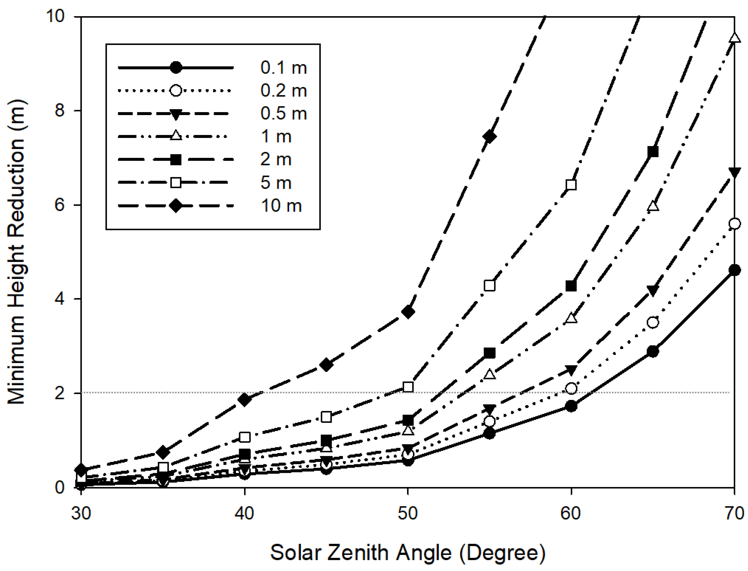
The graph shown in Figure 5 illustrates variations of minimum detectable height reduction (ΔHmin) for spatial resolutions ranging from 0.1 to 10 m and imagery acquired at solar elevation angles ranging from 30 to 70 degrees. The values of ΔHmin are lowest in the highest spatial resolution imagery case for minimal solar elevation angle. Therefore, in the case of an earthquake disaster, the highest detection performance can be expected when using higher resolution imagery with longer shadow length (in lower latitude areas and/or during the summer season). A further consideration is the anticipated ΔHmin given the structure of buildings, namely, one story. If the ΔHmin is at least 3 m, shadow change detection methods will not be feasible using imagery with a resolution of 5 m or above since ΔHmin value will exceed 3 m unless the solar elevation angle is less than 30 degrees. As an example of a real image source, for the Pleiades data acquired at a solar elevation angle of 45.9° over downtown Calgary (at about 51° N latitude) used in this work, the value of ΔHmin is about 0.516 m for the PAN-sharpened image with 50 cm resolution and is about 2.06 m for the multispectral image with 2 m resolution.
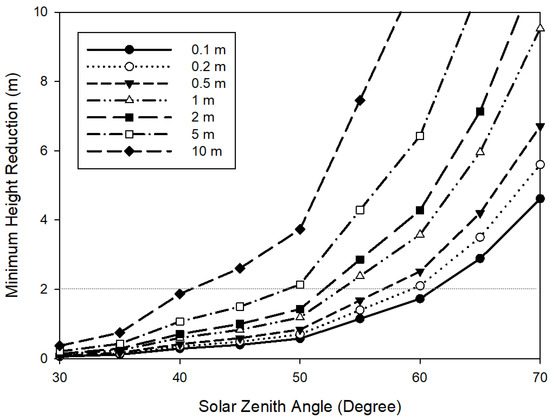
Figure 5.
The estimated detection error as the detectable minimum height reduction (ΔHmin) related to the image spatial resolution and solar elevation angle.
3. Results
3.1. Case A—Based on Simulated Building DSM
For the building damage simulation in Case A, the damaged building types discussed in Table 1 are used to generate simulated damage candidates. A total of ten buildings with a box shape have been used to simulate pre- and post-event (i.e., no damage and damage cases) pairs for shadow comparison. The focus of the investigation addresses changes in building shadow patterns based on perfect baseline DSM information, i.e., it is assumed that there are no errors associated with the DSMs.
Figure 6 illustrates an example of the simulation of the pre-event building DSMs and post-event damaged buildings. Five of the ten buildings are oriented with a similar orientation (north–south and east–west sides), while the remaining five have randomly selected orientations. In the first group, a lower building is close to and behind a taller building. The heights of other buildings are set randomly with a maximum building height set to 100 m. The simulated pre-damage building dataset (upper-left) and post-damage dataset of buildings with various types of damages (middle-left) are shown in Figure 6.
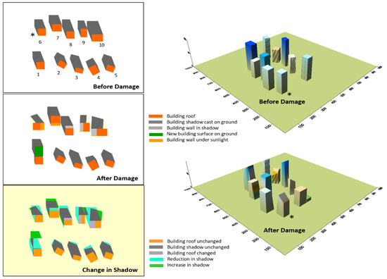
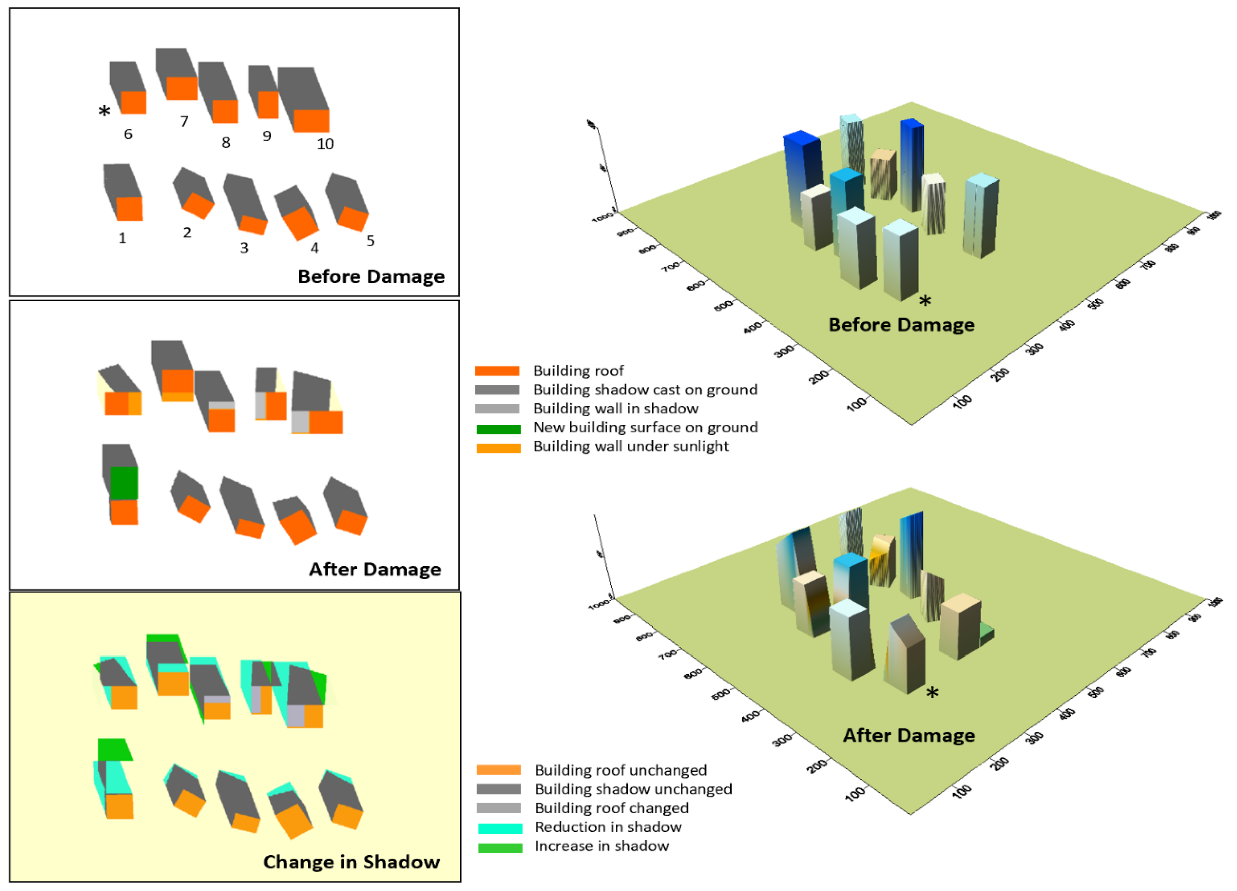
Figure 6.
Building DSM maps in 3D (right), building shadows, and changes for the before- and after-damage scenario (left) for the Case A study. The mark ‘*’ indicates the location of a building in different pictures.
The damage types in Figure 6 are height reduction (building numbers 2, 3, 4, and 5), inclination (building numbers 6, 7, 8, 9, and 10), and overturn (building number 1). The damage parameters such as leaning angle, leaning direction, overturn direction, and reduction in height and shape of the damaged building tops are randomly selected in the simulation. In this scenario, the solar elevation and azimuth angles have been selected to match those of the acquisition time of the Pleiades image. Perspective views of the building cases are also shown in Figure 6 right. The changes in building shadows corresponding well with the building damage, especially the changes in shadow, readily revealed the building damage well in the cases of the height-reduction and inclination damage of buildings with intact roofs that are not obvious in the two-dimensional imagery. In the height-reduced building damage cases, all of the shadow changes are in the shadow length along the solar azimuth direction, i.e., the shadows of the damaged buildings lie within the shadow areas of their undamaged counterparts. The height reduction of a damaged building can be estimated from the reduced length of the shadow pattern as measured in the solar azimuth direction. If height reduction is also coupled with roof deformation, this deformation will result in additional shadow shape change, as shown in the buildings labeled 2, 3, 4, and 5 in Figure 6. The presence of these additional shadow elements provides a cue in the classification of damage types.
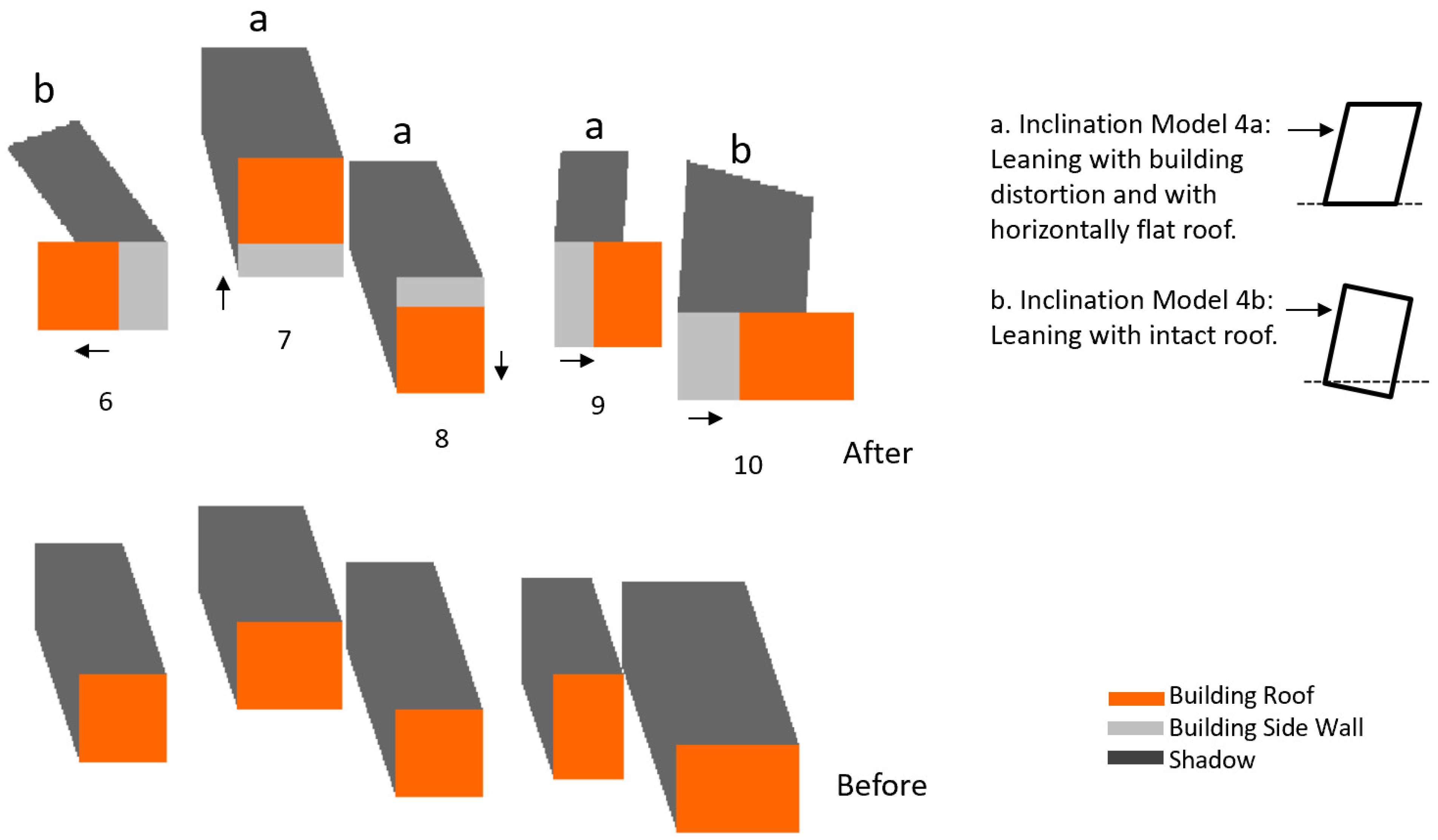
For the inclination damage cases, two sub-types that are common in earthquake-induced building damage are considered, as shown in Figure 7. One is that one side of the building sinks into the soil and the building is without roof distortion (noted as a in Figure 7), and the other is where the building leans to one side, but the roof remains horizontal and flat (examples labeled b in Figure 7). Cases of the latter sub-type are often observed in wood-structured buildings. Detecting both sub-types of damages from images is very challenging since the roofs of the buildings remain intact. Figure 6 and Figure 7 demonstrate that the significant shadow changes between pre- and post-event images should provide reliable cues and quantitative information of damage conditions.

Figure 7.
Detailed demonstration of building examples with two types of inclination damages for the Case A study.
Additional complications in shadow change interpretation can arise when shadows of multiple buildings overlap and when the shadow of a tall building is cast on the roof of a neighboring lower building. The height differential between the buildings must be taken into account when estimating the damage-related height reduction of the taller building. Further complications can arise as an observed shadow segment can be a composite that contains shadow contributions from more than one building.
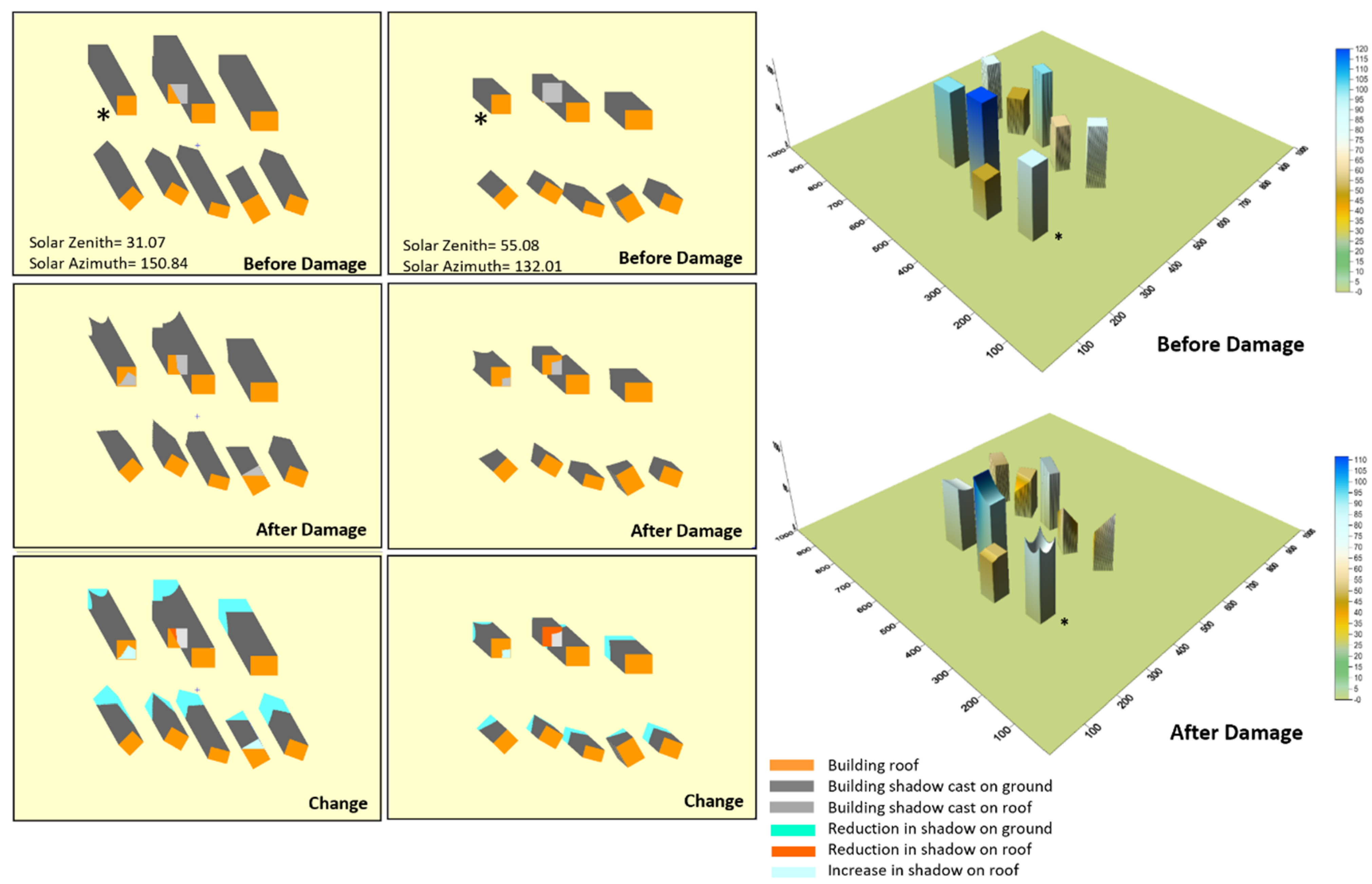
The shadow changes and patterns vary depending on the solar elevation angle and solar azimuth angle, i.e., damage detection performance based on shadow change will vary with season and time of day. Figure 8 illustrates examples of the building shadows in cases of lower or higher solar zenith angles, in which ten buildings with various types of height-reduced damage are under investigation. The shadow changes in autumn (lower solar zenith angle, left panel) are obvious with larger change areas in the shadow patterns, compared to those in summer (higher solar zenith angle, right panel). On the one hand, shadow-based building damage detection should be more effective for isolated buildings. In dense urban areas, however, the complications noted above regarding overlapping building shadows and shadows cast by one building on another will be more acute in lower solar zenith angle conditions.
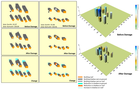
Figure 8.
Building shadows and changes for pre- and post-damage scenarios with high and low solar zenith angles. The scales are in meters. The mark ‘*’ indicates the location of a building in different pictures.
3.2. Case B—Analyses Using LiDAR-Based Building DSM
3.2.1. Comparison of Pleiades and Predicted Baseline Shadows
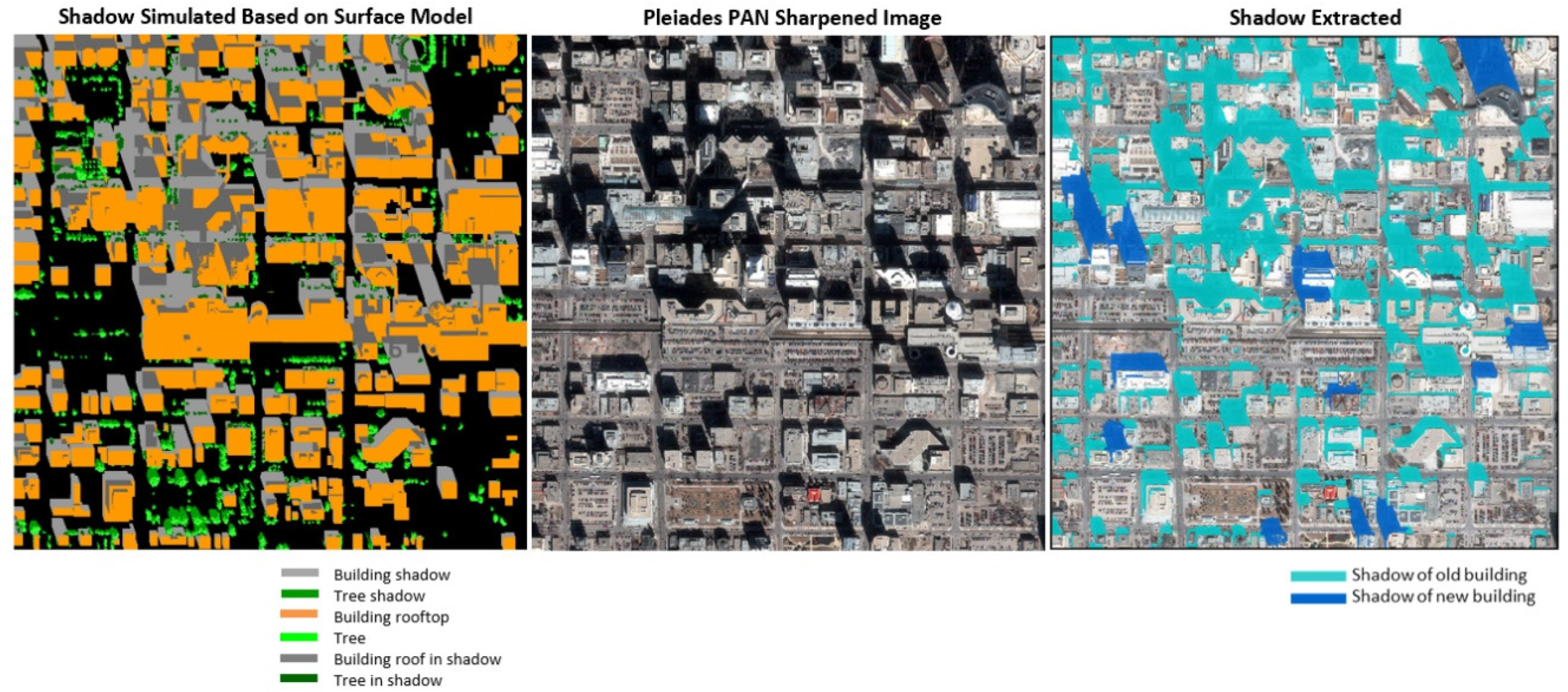
A baseline building shadow map was generated (Figure 9, left) using the Calgary LiDAR-based DSM with the solar parameters corresponding to the acquisition date and time of the Pleiades image. This baseline shadow product has been compared with the Pleiades PAN-sharpened image (Figure 9, middle) and the shadow map extracted from the Pleiades image (Figure 9, right). Overall, the predicted and extracted shadows of buildings exhibit good agreement. However, as updating of LiDAR information from new flights is usually infrequent compared to that of optical multispectral image acquisition, there is generally a difference associated with recent urban change. As shown in Figure 9, there are several locations of significant disagreement due to the difference of acquisition dates between the LiDAR and Pleiades multispectral image for the Calgary case. These disagreements can be explained by (A) new building construction in previously open land, (B) where old buildings have been replaced or altered, and (C) old building removal resulting in open land. The difference in the building shadows between the DSM-based shadow map and those extracted from a pre-event image (in this case the Pleiades image) can be used to detect these urbanization-development changes and in so doing identify limitations of the information content of a DSM source that might be employed in the future for damage assessment purposes and also emphasizes the need for up-to-date pre-event information, especially in highly dynamic landscapes. There is a need to develop a pre-event baseline shadow change map as a reference for response use, which provides disagreement due to the acquisition difference of data sets. To illustrate this pre-event application, Figure 10 provides a baseline shadow classification map through shadow matching using two shadow maps from different sources. Overall, the two shadow maps agree well. Furthermore, by comparing these with the predicted shadow from the LiDAR-based DSM, shadows related to new buildings in the multi-spectral image can be detected and identified and more detail of the similarity and differences between them can be derived as shown in Figure 10. First, shadows cast by small objects on building roofs (e.g., heating/air conditioning units) can be identified and extracted from the multi-spectral image. These details may be missing in the LiDAR-derived DSM map depending on the relative spatial resolution of the image and DSM. Since the small features on the building rooftops and their shadows can provide detailed information about the morphology of the building in question, the spatial details in the baseline building DSM map are important factors influencing the accuracy of the damage detection based on the building shadow information. Second, the DSM counts the height information of an object only using the vertical length from the object’s top surface but not the three-dimensional shape of the object. The three-dimensional shape of an object like a TV tower with the shape narrowed down in the lower part cannot be represented well with the DSM. Therefore, in this case, there is a difference in the shadow pattern of the TV tower between the simulated shadow map from LiDAR-based DSM and the map extracted from the image.

Figure 9.
Simulated shadow map (left) and building shadow map (right) extracted from Pleiades image (middle) for the Case B study.
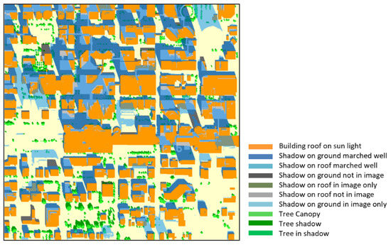
Figure 10.
Baseline map of building shadows.
The LiDAR-based building DSM map is assumed to be an accurate representation of the real morphology distribution of the buildings. From the analysis above, a high similarity of the pre-event building DSM map to reality is essential for effectively building damage detection based on shadow information. However, as described above, there can be a gap between the DSM map and the reality at the time of a disaster event. A baseline map of differences (natural differences) between the shadow map from the LiDAR-based DSM and the extracted shadows from the image before the event is necessary. The baseline differences result from causes such as building changes that have occurred between the LiDAR and image acquisitions. The baseline shadow difference map as shown in Figure 10 is an important information layer as reference information for validation of the shadow changes in real-time and can also be used to update the baseline building DSM map for preparation. Furthermore, for disaster-prone areas, it is a necessity to acquire new LiDAR imagery on a frequent basis to update the DSM.
3.2.2. Shadow Changes from Simulated Building Damage
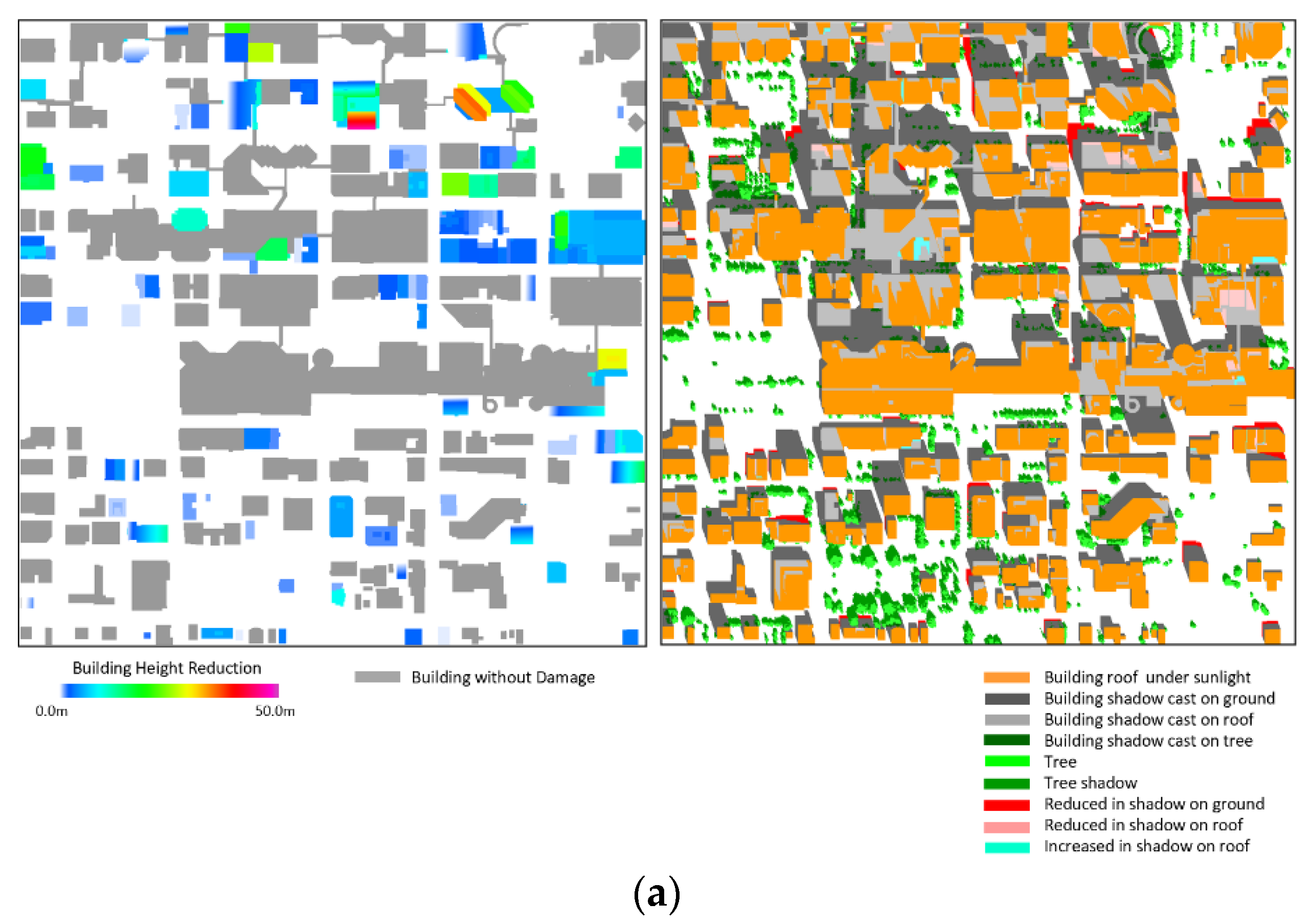
Building damage scenarios have been simulated with randomly selected values of the building damage parameters (reduced height, leaning angle/direction, overturn direction, etc.) applied to selected building objects in the LiDAR-derived DSM map. Candidate buildings have been randomly selected from the available building footprint map. Furthermore, for each damaged building, the damage type has been randomly assigned from the building damage categories (Models 1–4) shown in Figure 1, while damage parameters for each building case have been assigned randomly selected values. For each scenario, differencing of the baseline shadow map and the simulated building damage map for each scenario has resulted in the creation of one of the shadow change maps. The solar parameters used for the shadow simulation are the same as those for the Pleiades image. Figure 11 illustrates the results from height-reduced building damages. The shadow change maps (right panel) for the two damage cases involve total damaged building areas of 30% and 50% as shown in Figure 11a and 11b, respectively, as well as the DSM maps of these two damage cases, respectively (Figure 12). The total damaged area of buildings is estimated by the accumulation of individual building areas. The changes in building shadow have three classes, shadow reduction on the ground and shadow reduction or increase on roofs. The red-colored shadow reduction areas on the group surface shown in the map resulted from building height-reduction damage. Since it is a downtown urban case with dense building distribution, the shadow changes due to building damage are also shown on the roofs of neighboring buildings; some of the shadow changes on roofs have been reduced (pink) or increased (bright blue), as shown in Figure 11.
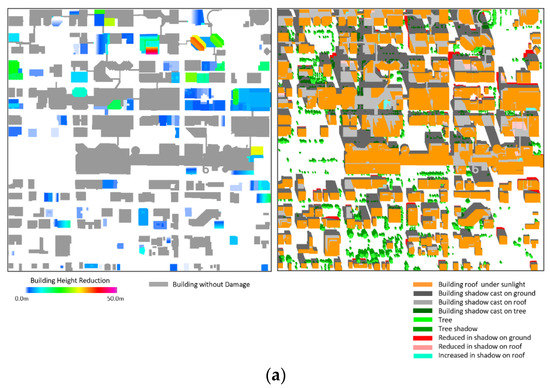
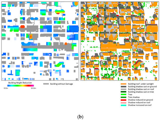
Figure 11.
(a) Maps of building shadows changes (right) and reduction in building height (left). The total building damage area is 30% of the total building footprint area in the Case B site. (b) Maps of simulated building shadows and shadow changes (right) and reduction in building height (left). The total building damage area is 50% of the total building footprint area in the Case B site.
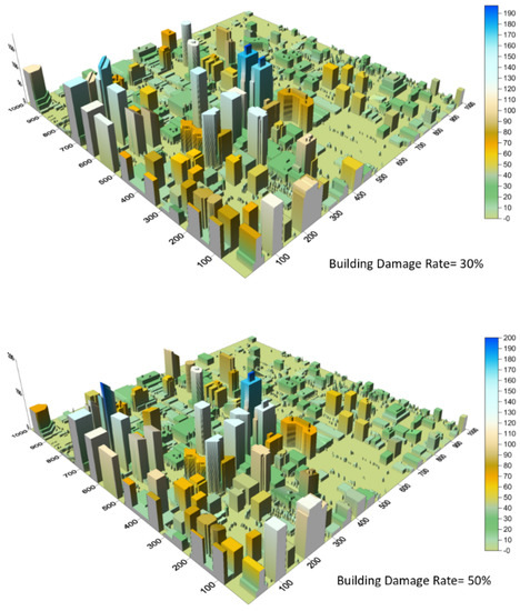
Figure 12.
DSM maps of 30% (upper) and 50% (lower) damaged building areas with the same scenarios as those shown in Figure 11. The scales are in meters.
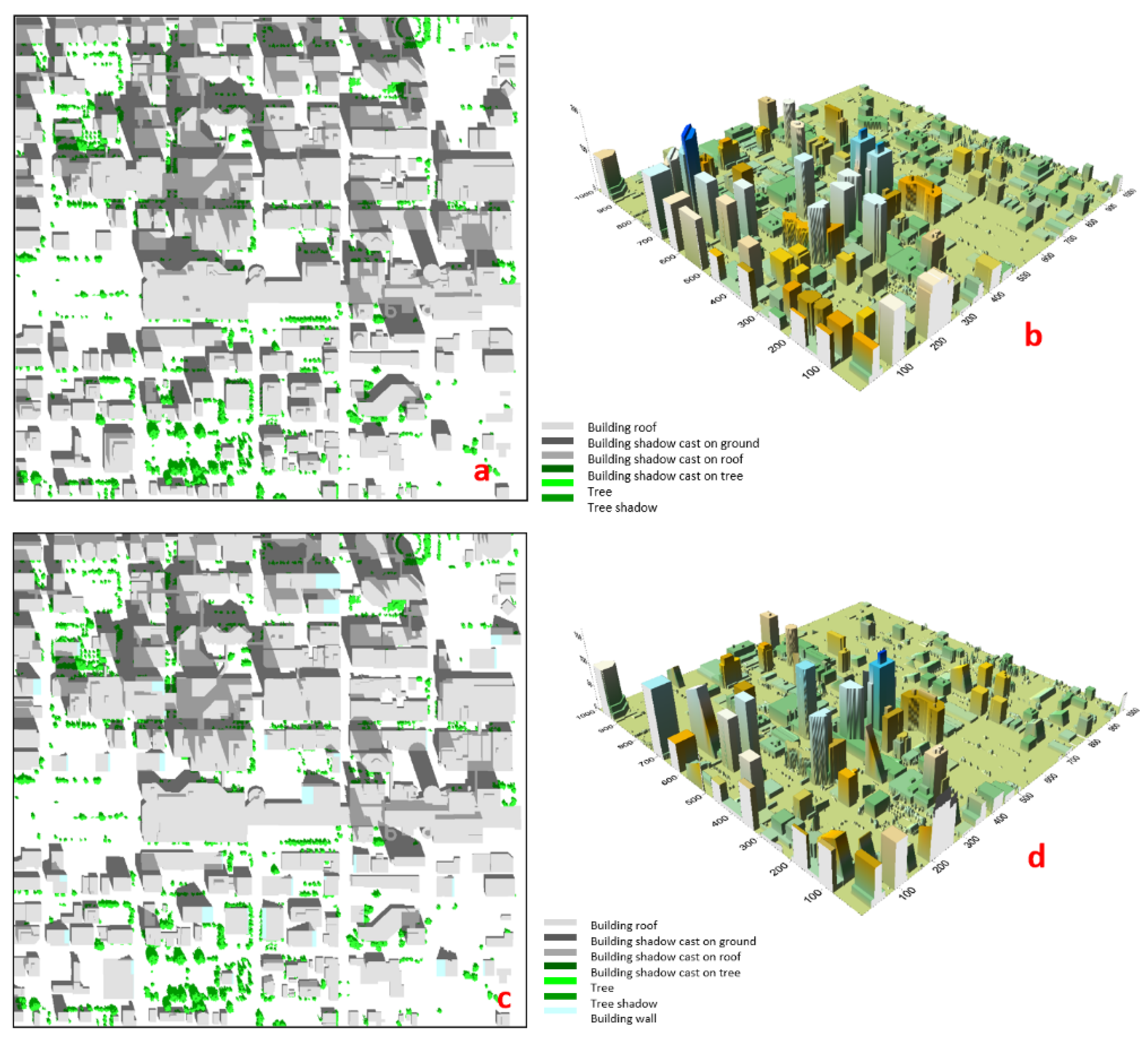
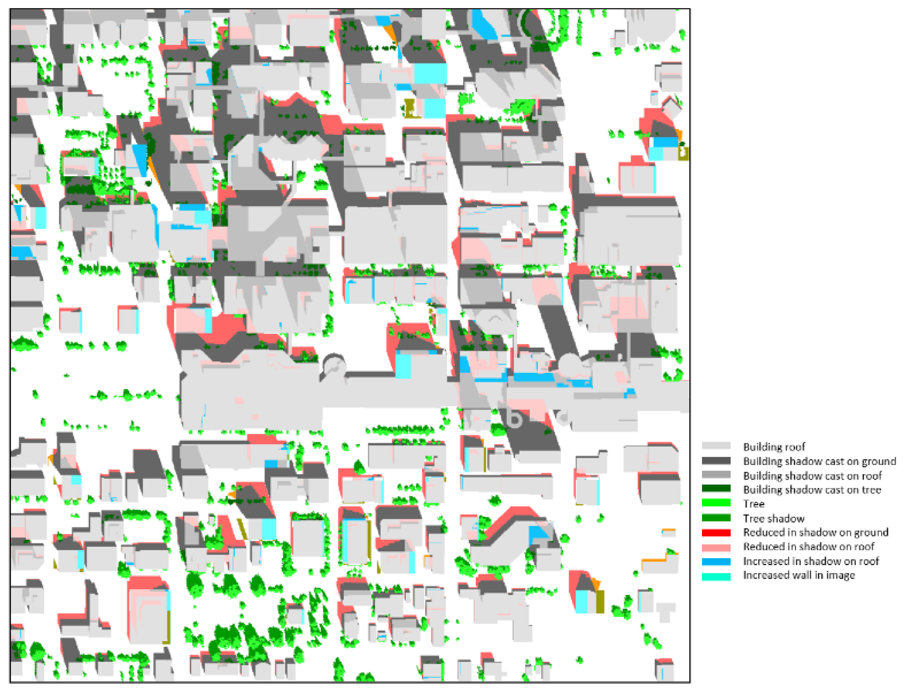
Figure 13 illustrates the results of all model building damage (height reduction, overturn, and inclination) with a scenario of 85% damaged building area, including the simulated shadow maps before and after damage (left panels) and the DSM maps before and after damage (right panels). Again, the generation of the building damage maps involves the random selection and assignment of the building damage parameters. Figure 14 demonstrates the shadow differences due to the building damages, which reveal the damaged building locations and also the damage conditions. The shadow areas are not only decreased on ground surfaces but also increased on roofs depending on the building damage conditions. In this map, the exposure of building walls due to inclination damages is also marked out. From the information given in the shadow difference map, the locations and conditions of the damaged building can be quickly identified during the real-time response.

Figure 13.
The baseline (a) and simulated (c) shadow maps, the baseline (b) and simulated post-damage (d) DSMs. The building damage simulated includes the building damage models listed in Table 1. The total building damage area is 85%.
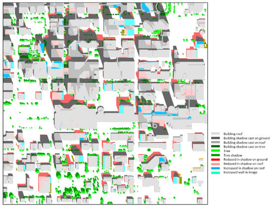
Figure 14.
Class map of shadow differences before and after damages derived from building damage case shown in Figure 13.
In Case B with a more complicated urban landscape with variation in built-up morphology and distribution of tall trees, most damaged buildings can be detected with the changes in shadows. However, it is noted that the changes in shadows under tree canopies and tree shadows, as well as in the case that shadows of damaged buildings cast on walls of neighboring buildings, cannot be detected in the image.
4. Conclusions and Discussion
The detection of damaged buildings that did not suffer collapse can be highly challenging from aerial or satellite optical imagery. A key information cue can be provided by a comparison of predicted building shadows based on pre-event building models with shadow estimates extracted from post-event imagery. For precise detection of damaged buildings without total collapse, a practical processing framework for EO-based detection of earthquake-induced building damages in dense urban areas has been proposed based on a comparison of pre- and post-event building shadows derived from DSM and multispectral image data. This processing framework includes (a) the extraction of post-event shadow patterns from multispectral image source; (b) the generation of a pre-disaster (or baseline) DSM derived from LiDAR data that encapsulates building morphologies; (c) the prediction, through DSM-based simulation, of the anticipated undamaged building shadow patterns at a post-event acquisition time for which multispectral imagery is available; (d) the generation of a baseline shadow change map due to pre- and post-event data acquisition date difference, which shows the natural shadow changes related to urban development; (e) the differencing of these two building shadow patterns to generate a shadow change map; and (f) the estimation of the building damage level/type for those buildings exhibiting significantly different shadow patterns.
The various common types of building damage caused by earthquakes, including height-reduced, inclination, and overturn, have been considered in this work, especially the inclination and height-reduced damaged buildings with intact roofs since these types of building damage are difficult to detect and identify from two-dimensional images from satellite or aerial plane sensors without shadow information. The detection of these damage classes with intact building roofs in remotely sensed imagery has high uncertainties using only roof spectral or texture information, even with manual interpretation. The use of relevant building shadow information is essential for EO-based detection of the damaged buildings mentioned above.
Through two case studies using building damage and shadow simulations, as well as analysis using the differencing between predicted and post-event shadows, based on building DSMs and extracted shadow information delineated from multispectral imagery, an in-depth investigation into the effectiveness and limitation of our proposed building damage detection framework was undertaken. A number of key findings from the investigation are summarized as follows.
- Shadow differencing information is essential for the rapid detection of damaged buildings that are not in total collapse.
- There is a limitation on the detection of building height changes based on the estimation of the shadow length from remote sensing imagery. This limitation is dependent on the fineness of the optical image spatial resolution, from which the post-event shadow patterns are extracted, and also is influenced by the solar elevation angle.
- One key step in damage detection is the differencing of the baseline shadow patterns between the DSM-based and image-based shadow maps. The baseline shadow difference map is essential in the processing as reference information for the rapid detection of damaged buildings. The differences in the baseline shadow maps result from several causes, such as errors in shadow extraction from imagery, the low quality of LiDAR data, and the lack of building DSM updating. The baseline shadow difference map information can be used for the validation of the building damage detection using the shadow change information and also for improvement of the baseline building DSM map information for response preparation.
- A high level of similarity of the baseline building DSM map with reality before the event is essential for building damage detection using the building shadow change information. Meanwhile, since the gap between the building DSM replica and the building morphology in reality is not avoidable, the information about the differences between the shadow maps from a LiDAR-based baseline surface model and from extraction from the image before the event are important information layers for the improvement of the detection accuracy.
Frequently updated LiDAR data over urban areas can provide accurate three-dimensional information about buildings and the urban renewal development, which are essential information for an emergency response to natural disasters [3], especially in urban areas. In recent years, as the technologies of LiDAR sensors and data processing have been improved, more DSM information layers in urban areas derived from LiDAR data with more frequent updating and improved quality and spatial resolution have been generated, which reduce the similarity gaps between the DSM and real morphology distribution. The improvement in urban DSM map information provides the opportunities for applications of effective shadow-based building damage detection for rapid disaster response.
Author Contributions
Conceptualization, methodology, software, formal analysis, investigation, data curation, writing—original draft preparation, Y.Z.; writing—review and editing, M.R.; partial visualization, S.G.L. All authors have read and agreed to the published version of the manuscript.
Funding
This research received no external funding.
Institutional Review Board Statement
Not applicable.
Informed Consent Statement
Not applicable.
Data Availability Statement
Not applicable.
Acknowledgments
The Airborne Imaging Inc. (airborneimaginginc.com), for providing the LiDAR image data. The authors would like to give thanks to Bert Guindon who provided constructive suggections to this work.
Conflicts of Interest
The authors declare no conflict of interest.
References
- Dong, L.; Shan, J. A comprehensive review of earthquake-induced building damage detection with remote sensing techniques. ISPRS J. Photogramm. Remote Sens. 2013, 84, 85–99. [Google Scholar] [CrossRef]
- Schweier, C.; Markus, M.; Steinle, E. Simulation of earthquake caused building damages for the development of fast reconnaissance techniques. Nat. Hazards Earth Syst. Sci. 2004, 4, 285–293. [Google Scholar] [CrossRef] [Green Version]
- Balsa-Barreiro, J. LiDAR for management in natural disasters and catastrophes. In Government Briefing Book: Emerging Technology & Human Rights; Greene, K.G., Ed.; Berkman Klein Center: Cambridge, MA, USA, 2019; Volume 1, p. 11. Available online: https://www.greenestrategy.com/brief (accessed on 1 July 2021).
- Tong, X.; Hong, Z.; Liu, S.; Zhang, X.; Xie, H.; Li, Z.; Yang, S.; Wang, W.; Bao, F. Building-damage detection using pre- and post-seismic high-resolution satellite stereo imagery: A case study of the May 2008 Wenchuan earthquake. ISPRS J. Photogramm. Remote Sens. 2012, 68, 13–27. [Google Scholar] [CrossRef]
- Sarp, G.; Erener, A.; Duzgun, S.; Sahin, K. An approach for detection of buildings and changes in buildings using orthophotos and point clouds: A case study of Van Erriş earthquake. Eur. J. Remote Sens. 2014, 47, 627–642. [Google Scholar] [CrossRef] [Green Version]
- Menderes, A.; Erener, A.; Sarp, G. Automatic detection of damaged buildings after earthquake hazards using remote sensing and information technologies. Procedia Earth Planet. Sci. 2015, 15, 257–262. [Google Scholar] [CrossRef] [Green Version]
- Turker, M.; Sumer, E. Building-based damage detection due to earthquake using the watershed segmentation of the post-event aerial images. Int. J. Remote Sens. 2008, 29, 3073–3085. [Google Scholar] [CrossRef]
- Rehor, M.; Bähr, H.-P.; Tarsha-Kurdi, F.; Landes, T.; Grussenmeyer, P.; Rehor, M. Contribution of two plane detection algorithms to recognition of intact and damaged buildings in lidar data. Photogramm. Rec. 2008, 23, 441–456. [Google Scholar] [CrossRef]
- Li, M.; Cheng, L.; Gong, J.; Liu, Y.X.; Chen, Z.J.; Li, F.X.; Chen, G.; Chen, D.; Song, X.G. Post-earthquake assessment of building damage degree using LiDAR data and imagery. Sci. China Ser. E Technol. Sci. 2008, 51, 133–143. [Google Scholar] [CrossRef]
- Dare, P.M. Shadow Analysis in High-Resolution Satellite Imagery of Urban Areas. Photogramm. Eng. Remote Sens. 2005, 71, 169–177. [Google Scholar] [CrossRef] [Green Version]
- Ngo, T.T.; Mazet, V.; Collet, C. Shape-based building detection in visible band images using shadow information. IEEE J. Sel. Top. Appl. Earth Obs. Remote Sens. 2017, 10, 920–932. [Google Scholar] [CrossRef]
- Bayramli, I.; Bondi, E.; Tambe, M. In the Shadow of Disaster: Finding Shadows to Improve Damage Detection. In Proceedings of the IJCAI 2020 AI for Social Good Workshop, Harvard University, Cambridge, MA, USA, 7–8 January 2021; Available online: https://aiforgood2020.github.io/papers/AI4SG_paper_76.pdf (accessed on 1 July 2021).
- Shettigara, V.K.; Sumerling, G.M. Height determination of extended objects using shadows in SPOT images. Photogramm. Eng. Remote Sens. 1998, 64, 35–44. [Google Scholar]
- Shao, Y.; Taff, G.N.; Walsh, S.J. Shadow detection and building-height estimation using IKONOS data. Int. J. Remote Sens. 2011, 32, 6929–6944. [Google Scholar] [CrossRef]
- Lee, T.; Kim, T. Automatic building height extraction by volumetric shadow analysis of monoscopic imagery. Int. J. Remote Sens. 2013, 34, 5834–5850. [Google Scholar] [CrossRef]
- Comber, A.; Umezaki, M.; Zhou, R.; Ding, Y.; Li, Y.; Fu, H.; Jiang, H.; Tewkesbury, A. Using shadows in high-resolution imagery to determine building height. Remote Sens. Lett. 2012, 3, 551–556. [Google Scholar] [CrossRef] [Green Version]
- Zhang, Y.; Guindon, B.; Xinwu, L.; Lantz, N.; Zhu, X.; Sun, Z. Synoptic mapping of high-rise buildings in urban areas based on combined shadow analysis and scale space processing. Int. J. Remote Sens. 2014, 35, 3616–3630. [Google Scholar] [CrossRef]
- Liasis, G.; Stavrou, S. Satellite images analysis for shadow detection and building height estimation. ISPRS J. Photogramm. Remote Sens. 2016, 19, 437–450. [Google Scholar] [CrossRef]
- Kadhim, N.; Mourshed, M. A shadow-overlapping algorithm for estimating building height from VHR satellite images. IEEE Geosci. Remote. Sens. Lett. 2018, 15, 8–12. [Google Scholar] [CrossRef] [Green Version]
- Bensaibi, M.; Saadi, S.; Bouder, A. Automatic detection of seismic damages from very high monoscopic spatial images. Asian J. Civ. Eng. 2020, 21, 1039–1050. [Google Scholar] [CrossRef]
- Vu, T.T.; Matsuoka, M.; Yamazaki, F. Shadow Analysis in Assisting in Damage Detection Due to Earthquakes from Quickbird Imagery. Available online: https://www.semanticscholar.org/paper/SHADOW-ANALYSIS-IN-ASSISTING-DAMAGE-DETECTION-DUE-Vu-Matsuoka/73c1273c029fefb055b58656fc07391d3be1e6e8 (accessed on 1 July 2021).
- Liu, C.; Sui, H.; Huang, L. Identification of Damaged Building Regions from High-Resolution Images Using Superpixel-Based Gradient and Autocorrelation Analysis. IEEE J. Sel. Top. Appl. Earth Obs. Remote Sens. 2020, 99. [Google Scholar] [CrossRef]
- Zhang, R.; Duan, K.; You, S.; Wang, F.; Tan, S. A novel remote sensing detection method for buildings damaged by earthquake based on multiscale adaptive multiple feature fusion. Geomat. Nat. Hazards Risk 2020, 11, 1912–1938. [Google Scholar] [CrossRef]
- Oludare, V.; Kezebou, L.; Panetta, K.; Agaian, S. Semi-supervised learning for improved post-disaster damage assessment from satellite imagery. SPIE Proc. 2021, 11734, 117340O. [Google Scholar] [CrossRef]
- Tong, X.; Lin, X.; Feng, T.; Xie, H.; Liu, S.; Hong, Z.; Chen, P. Use of shadows for detection of earthquake-induced collapsed buildings in high resolution satellite imagery. ISPRS J. Photogramm. Remote Sens. 2013, 79, 53–67. [Google Scholar] [CrossRef]
- Schweier, C.; Markus, M. Assessment of the search and rescue demand for individual buildings. In Proceedings of the 13th World Conference on Earthquake Engineering, Vancouver, BC, Canada, 1–6 August 2004. [Google Scholar]
- Schweier, C.; Markus, M. Classification of collapsed building for fast damage and loss assessment. Bull. Earthq. Eng. 2006, 4, 177–192. [Google Scholar] [CrossRef]
- Hermosilla, T.; Palomar-Vázquez, J.; Balaguer-Beser, Á.; Balsa-Barreiro, J.; Ruiz, L.A. Using street-based metrics to characterize urban typologies. Comput. Environ. Urban Syst. 2014, 44, 68–79. [Google Scholar] [CrossRef] [Green Version]
- Zhang, Y.; Leblanc, S. Mapping of damaged buildings through simulation and change detection of shadows using LiDAR and multispectral data. SPIE Remote Sens. Proc. 2019, 11157. [Google Scholar] [CrossRef]


Publisher’s Note: MDPI stays neutral with regard to jurisdictional claims in published maps and institutional affiliations. |
© 2021 by the authors. Licensee MDPI, Basel, Switzerland. This article is an open access article distributed under the terms and conditions of the Creative Commons Attribution (CC BY) license (https://creativecommons.org/licenses/by/4.0/).