Article

Underground Goaf Parameters Estimation by Cross-Iteration with InSAR Measurements

School of Geosciences and Info-Physics, Central South University, Changsha 410083, China
*
Author to whom correspondence should be addressed.
Remote Sens. 2021, 13(16), 3204; https://doi.org/10.3390/rs13163204
Submission received: 8 July 2021 / Revised: 2 August 2021 / Accepted: 10 August 2021 / Published: 12 August 2021
(This article belongs to the Special Issue Advances in InSAR Imaging and Data Processing)

Abstract

:
Determining the geographic location and spatial distribution of underground goaf is of great significance for the prevention of mining subsidence hazards and the detection of illegal mining. However, traditional goaf detection techniques mainly focus on geophysical methods that are labor intensive, have low efficiency, and are expensive. Due to the large range and off-site monitoring capability of interferometric synthetic aperture radar (InSAR) techniques, research on goaf location detection based on InSAR measurements has been increasing. This paper proposes a new method for locating underground goaf based on cross-iteration and InSAR measurements. Firstly, the functional relationship between the geometric parameters of the goaf and the line of sight (LOS) deformation retrieved by InSAR techniques is constructed. Then, the three initial model parameters of the probability integration method (PIM) are determined by mining geological conditions. Finally, the cross-iteration method is used to determine the parameters to characterize the spatial location of underground goaf. The experimental results show that the average relative errors of the simulated experiment and the real experiment are 1.5% and 5.1%, respectively, and the inverted goaf parameters are in good agreement with the real values. Moreover, the proposed method only requires the main lithology of the overlying rock in the goaf and does not depend on the accuracy of PIM model parameters. Therefore, this method has engineering application value for the detection of goaf lacking actual measurement data or that caused by illegal mining.

1. Introduction

Underground coal mining is the main way to obtain coal resources. The underground cavities formed by the mining of coal seams are called goafs. With the large-scale mining of coal, a large number of unknown goafs mainly caused by illegal mining activities have been generated in the world. In addition, the destruction or loss of ancient coal seam mining records make it difficult to know the actual situation of many abandoned goafs. These unknown goafs may not only endanger people’s lives and property and destroy surface infrastructure, but also cause landslides, surface subsidence, and other geological disasters. Therefore, determining the geographic location and spatial distribution of underground goafs is of great significance for the early warning and management of geological disasters. Traditional underground goaf detection technologies focus on geophysical techniques, such as transient electromagnetic method [1,2], microgravity measurement [3], and remote thermal IR surveying [4]. These methods can roughly determine the spatial distribution and geographic location of the goaf. However, they are time-consuming, labor-intensive, costly, and have a small detection range.
Interferometric synthetic aperture radar (InSAR) is a new technology that can use the interferometric phase information of SAR image pairs to obtain the surface deformation in the line of sight (LOS) direction [5]. InSAR technology can provide wide area coverage, high spatial resolution, and high monitoring precision of surface deformation fields [6,7]. It is gradually being used in many fields, such as the monitoring of volcanic activities [8,9], permafrost [10,11,12,13], landslides [14,15], and earthquakes [16,17,18,19]. In addition, InSAR techniques have many successful applications in critical infrastructure monitoring fields [20,21,22]. Moreover, with the continuous development of InSAR technology, a wealth of SAR sensors and a large number of historical archived images already exist, and free SAR image acquisition methods are constantly enriched. Compared with traditional goaf detection technology, InSAR technology has the unique advantages that provide the possibility for precise detection and positioning of goaf in a large area [23].
At present, there are few studies using InSAR monitoring results to locate goaf. In 2013, Hu et al. [24] proposed a differential InSAR (DInSAR)-based illegal-mining detection system (DIMDS), which can determine the center geographic coordinates of the underground goaf by combining the acquired LOS deformation and the mining subsidence law. However, the rough center coordinates of the goaf are not sufficient to accurately assess potential geological disasters. In order to obtain more effective goaf geometric information, Yang et al. [25] have constructed the functional relationship between the LOS deformation and the eight parameters of underground goaf based on the probability integration method (PIM). Then, the SAGA hybrid algorithm [26] was used to invert the unknown goaf parameters. However, the complexity of the function model will affect the efficiency of parameter inversion. Du et al. [27] extracted feature points on the sinking curves to participate in the calculation of the coal seam boundary and mining depth. Subsequently, Xia et al. [28] proposed a goaf positioning method that can calculate more parameters and is suitable for inclined coal seams. Similar to the method proposed by [27], this method ignores the influence of horizontal deformation and obtains incomplete goaf parameters. More importantly, these methods [25,27,28] all require prior model parameters of the PIM that are usually obtained from measured data. If the actual measurement data are insufficient, large PIM model parameter errors may be introduced, and the positioning accuracy of underground goafs may be seriously affected. Therefore, reducing the number and accuracy requirements of PIM model parameters plays an important role in the precise positioning of the unknown goaf.
In summary, this paper presents a cross-iteration method for accurate inversion of full underground goaf parameters. This method reduces the input of model parameters of the PIM and is not significantly affected by the accuracy of the required model parameters. We first modify the PIM model to reduce the input model parameters. Then, we constructed the functional relationship between the LOS deformation and the geometric parameters of the goaf and determined the three initial model parameters of the PIM related to the geological mining conditions. Finally, the geometric parameters of the goaf were inverted by a cross-iteration method. The reliability of the method was verified through simulation experiments and real experiments.
The remaining structure of the paper is as follows. The principle of the cross-iteration method is described in Section 2. Experiments and results are shown in Section 3 and Section 4, respectively. We state the discussion in Section 5, and the conclusion is presented in Section 6.

2. Cross-Iteration-Based Methodology

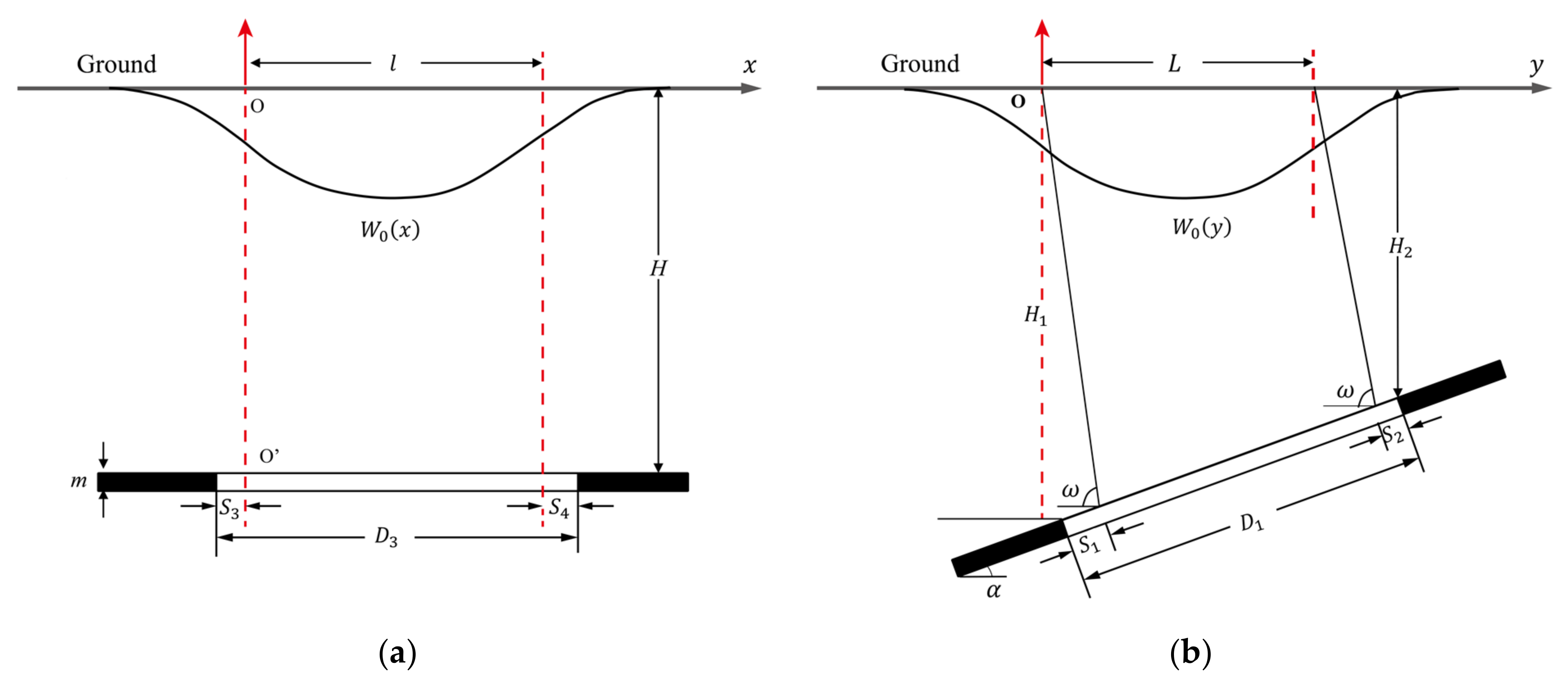
2.1. Principle of the PIM

The PIM model is a widely used mining subsidence prediction model developed on the basis of the random medium theory [29,30]. This model divides the goaf into many small mining units and regards the impact of mining on the ground surface as the sum of the mining impacts of all small units [31]. Supposing that there is an underground goaf caused by long-wall mining, in order to determine the geographic location and spatial distribution of this underground goaf, a set of parameters is usually required. This set of parameters usually obtained through actual observations is regarded as the geometric parameters of the goaf. As is shown in Figure 1, the geometric parameters of the goaf are given by a true boundary length D 3 , true boundary width D 1 , coal seam mining height m , dip angle α , geodetic coordinate of the origin X 0 , Y 0 , and azimuth angle of mining direction φ N , i.e., G P = m , H , α , D 3 , D 1 , φ N , X 0 , Y 0 . As long as the mining direction and related parameter values are determined, the vertical deformation W x , y and horizontal deformation U x , y , φ in φ direction at a point x , y can be predicted based on the PIM model [32].
W x , y = W 0 x W 0 y / W m a x
U x , y , φ = U 0 x W 0 y cos φ + W 0 x U 0 y sin φ / W m a x
with
W 0 x = W m a x erf π x r erf π x l r / 2
W 0 y = W m a x erf π y r 1 erf π y L r 2 / 2
U 0 x = b W m a x exp π x 2 r 2 exp π x l 2 r 2
U 0 y = b W m a x exp π y 2 r 1 2 exp π y L 2 r 2 2 + cot ω W 0 y
In Equations (1) and (2), W m a x = m q cos α is the maximum subsidence value of the ground; q is the subsidence factor; W 0 x and W 0 y are the vertical subsidence on the main section of the strike and dip directions, respectively (see Figure 2); U 0 x and U 0 y are the horizontal deformations on the main section of the strike and dip directions, respectively. Furthermore, l = D 3 S 3 S 4 and L = D 1 S 1 S 2 sin α + ω / sin ω are the calculated boundary length and width of the goaf, where ω (see Figure 2b) is the influence propagation angle of mining, S 3 , S 4 , S 1 , and S 2 (see Figure 2) are the offsets of inflection points in strike-back, strike, down-dip, and up-dip directions. r 1 = H 1 / tan β 1 , r 2 = H 2 / tan β 2 , and r = H / tan β   are the main influence radius in down-dip, up-dip and strike directions, respectively, where tan β , tan β 1 , and tan β 2 are the tangents of the major influence angles in the three directions. H (see Figure 2a) is the average mining depth, H 1 and H 2 (see Figure 2b) are the mining depths in down-dip and up-dip directions, and b is the horizontal displacement constant.
In addition to the geometric parameters of the goaf G P = m , H , α , D 3 , D 1 , φ N , X 0 , Y 0 , there are a set of model parameters M P 0 = q , b , tan β , tan β 1 , tan β 2 , ω , S 3 , S 4 , S 1 , S 2 that depend on the geological mining conditions [31]. Model parameters of the PIM are usually determined based on actual measured data and will vary with different geological mining conditions. The tangent of the major influence angle depends on the main properties of the overlying rock [25,31]. It can be approximately assumed that the tangents of the major influence angle in three directions are equal, i.e., tan β = tan β 1 = tan β 2 . The offsets of the inflection points S i i = 1 , 2 , 3 , 4 are only used to obtain the calculated boundary length l and width L of the goaf, and S 3 + S 4 and S 1 + S 2 are negatively correlated with the actual boundary length and width of the goaf, respectively. In order to simplify the PIM model, we can assume that S 3 = S 4 and S 1 = S 2 . Based on the above assumptions, the model parameters are modified to M P = q , b , tan β , ω , S 3 , S 1 , which not only simplifies the PIM model, but also reduces the difficulty for model parameter acquisition.

2.2. Underground Goaf Parameters Estimation by Cross-Iteration

2.2.1. The Function Model Linking InSAR LOS Measurement to Goaf Parameters

Using InSAR technology to monitor surface deformation can obtain millimeter-level or even higher precision LOS deformation fields. Based on the imaging geometry of SAR, the InSAR-derived deformation D L O S can be regarded as the comprehensive projection of the north–south, east–west, and vertical deformation components D N , D E , D W in the LOS direction.
D L O S = cos θ D W + sin θ sin σ D N sin θ cos σ D E
where θ is the incidence angle of the SAR sensor; σ is the heading angle. The PIM model can predict the 3D displacement of the surface settlement point and fully includes the required spatial distribution parameters of the goaf. Therefore, substituting Equations (1) and (2) into Equation (7), we can construct the functional relationship between the LOS deformation and the PIM model.
D L O S x , y = cos θ sin θ sin σ sin θ cos σ T W x , y , G P , M P U x , y , φ N , G P , M P U x , y , φ E , G P , M P
According to Equation (8), when the model parameters M P are known, the non-linear optimization algorithm can be selected to reverse the geometric parameters of the goaf G P . Moreover, using the large-area surface deformation data monitored by InSAR to directly invert fewer geometric parameters of the goaf inevitably reduces the calculation efficiency. Therefore, selecting an appropriate subsampling method not only effectively avoids data redundancy, but also saves sufficient data information. In this paper, an adaptive quadtree subsampling method [33,34] is selected to process deformation points. Compared with the traditional quadtree method, this method can divide irregular polygonal areas and reduce the influence of null values in InSAR data.

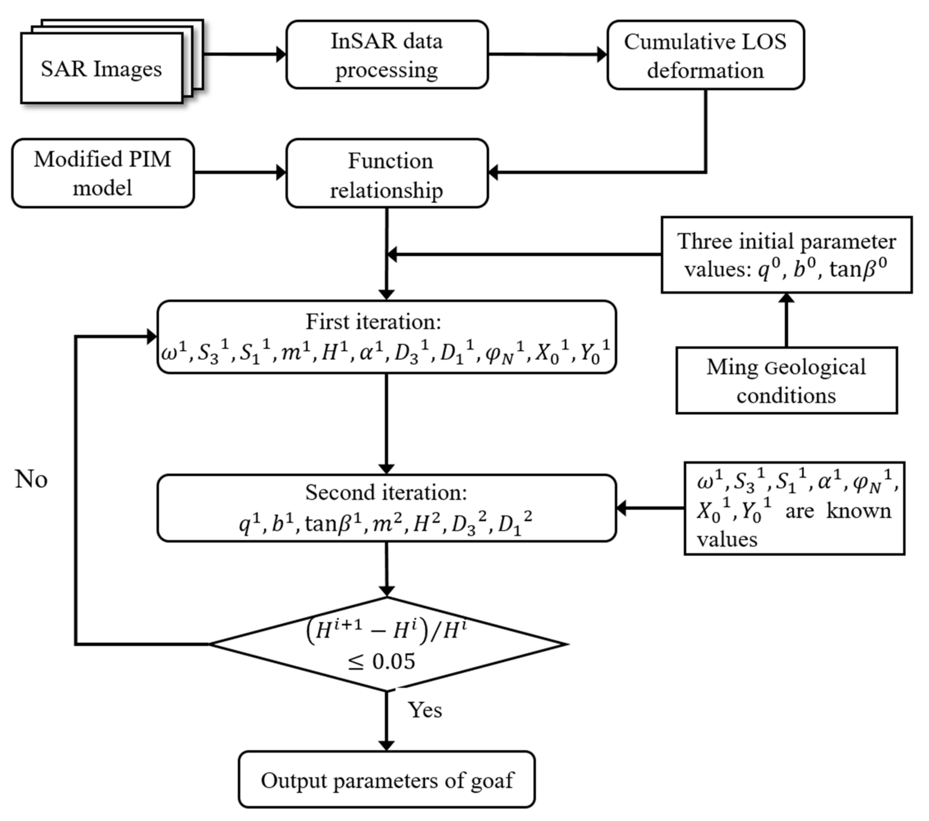
2.2.2. Model Resolution via Cross-Iteration

The PIM model is complex and nonlinear, which makes it difficult to directly determine the value of the model parameters M P . For mining areas lacking actual measurement data, model parameters of mining areas with similar geological structure conditions or model parameters of different working faces in the same mining area are usually used as approximate replacements. Thus, large model parameter errors may be introduced, which will result in lower inversion accuracy. In addition, a set of empirical parameters can also be determined according to the geological mining conditions, which may also seriously affect the inversion accuracy. Therefore, a cross-iteration method for the inversion of goaf parameters is proposed. This method only needs the empirical values of three initial model parameters q , b , tan β to obtain the goaf location results with high accuracy. Cross-iteration is an iterative method of cross-updating between grouped parameters, through the optimization algorithm to invert the pending parameters of each iteration. Since the magnitude of the subsidence factor q , the horizontal displacement constant b , and the tangent of the major influence angle tan β is small, the value interval is easily determined. First, we can obtain the empirical values of these three model parameters q 0 , b 0 , tan β 0 according to the main properties of the overlying rocks in the goaf. Then, we must select an improved genetic algorithm (GA) [32] to invert the goaf parameters m , H , α , D 3 , D 1 , φ N , X 0 , Y 0 and the remaining model parameters ω , S 3 , S 1 . The fitness function of the improved GA can be expressed as f = min D L O S x , y D L O S x , y , where D L O S x , y is the predicted LOS deformation based on Equation (8).
The processing steps of the improved GA are as follows: By repeatedly running GA for n times, n solutions P i i = 1 , 2 , , n and corresponding fitness values f P i i = 1 , 2 , , n can be obtained. Then, the RMSES of each parameter were calculated based on the n GA-derived resolutions. Subsequently, we eliminated solutions with an error of more than twice the corresponding RMSES. Finally, the reciprocal of the fitness values f P i 1 i = 1 , 2 , , m were used to weight the remaining m solutions P i 1 i = 1 , 2 , , m to obtain the unknown parameters P f i n a l , i.e.,
P f i n a l = 1 m P i 1 / f P i 1 1 m 1 / f P i 1
The influence propagation angle of mining ω , the offsets of inflection points S 3 , S 1 , the dip angle α , the azimuth angle of mining direction φ N , and the geodetic coordinate of the origin X 0 , Y 0 are less affected by q 0 , b 0 , tan β 0 . Therefore, these seven parameters are used as known to invert the remaining parameters using the improved GA. In this way, two iterations were carried out, and a crossover process was completed. When the ratio of the difference between the mining depths obtained in two adjacent iterations to the previous mining depth is less than the threshold, the geometric parameters of the goaf are relatively stable. Thus, the cross-iteration is terminated. The specific process of cross-iteration (see Figure 3) is as follows.
(1)
First Iteration: Determine the empirical values of the three initial model parameters q 0 , b 0 , tan β 0 and invert the remaining unknown parameters ω 1 , S 3 1 , S 1 1 , m 1 , H 1 , α 1 , D 3 1 , D 1 1 , φ N 1 , X 0 1 , Y 0 1 .
(2)
Second Iteration: Treat ω 1 , S 3 1 , S 1 1 , α 1 , φ N 1 , X 0 1 , Y 0 1 as known and update the remaining parameters to q 1 , b 1 , tan β 1 , m 2 , H 2 , D 3 2 , D 1 2 .
(3)
Iteration Termination Judgment: When the condition H 2 H 1 / H 1 0.05 is satisfied, the iteration is terminated, and the target parameter value is m 2 , H 2 , α 1 , D 3 2 , D 1 2 , φ N 1 , X 0 1 , Y 0 1 . If the termination condition is not satisfied, the parameter values q 1 , b 1 , tan β 1 obtained in the second iteration are used to repeat the two steps (1) and (2) until it is satisfied H i + 1 H i / H i 0.05 .

2.2.3. Overall Processing

The proposed method in this paper is essentially based on the constructed function model to perform a cross-iterative inversion to obtain the required parameters. Therefore, we first had to build a function model. Prior to this, InSAR data processing was required to obtain the cumulative LOS deformation within the target time range. Then, we linked the modified PIM model shown in Section 2.1 with the cumulative LOS deformation to construct the inversion model of the goaf parameters. Subsequently, the empirical values of the initial model parameters were determined according to the mining geological conditions of the study area. At this point, we had completed the preparatory work before the cross-iteration processing. Finally, we performed the inversion of the goaf parameters according to the cross-iteration steps shown in Section 2.2.2 and output the results. In this way, we completed the goaf positioning process as shown in Figure 3.

3. Experiments

3.1. Simulated Experiment

A simulated experiment was carried out. At first, a ground displacement field was simulated. We assumed that there was an underground goaf with a coal seam mining height of 3 m, a boundary length of 600 m, a boundary width of 150 m, a dip angle of 12°, a mining direction angle of 100°, and an average mining depth of 500 m. The overlying rock of the assumed goaf was mainly medium sandstone and limestone. The large mining depth and the type of overlying rock determined the continuity of surface deformation. Subsequently, we simulated the 3D displacements of the surface caused by the mining of the goaf. Assuming that the incidence angle and heading angle of the SAR sensor were 33.66° and −10.39°, the 3D displacements were converted to the simulated LOS deformation observations according to Equation (7). The spatial resolution of the simulated LOS deformation is 5 m × 5 m. As can be seen in Figure 4, the LOS deformation basin was approximately symmetrical, the largest deformation point was located in the center of the basin, and the largest deformation value was 0.54 m. Moreover, the relative positional relationship between the simulated goaf (the black polygon in Figure 4) and the LOS deformation basin in the same plane conformed to the characteristics of mining subsidence.

3.2. Real Data Experiment
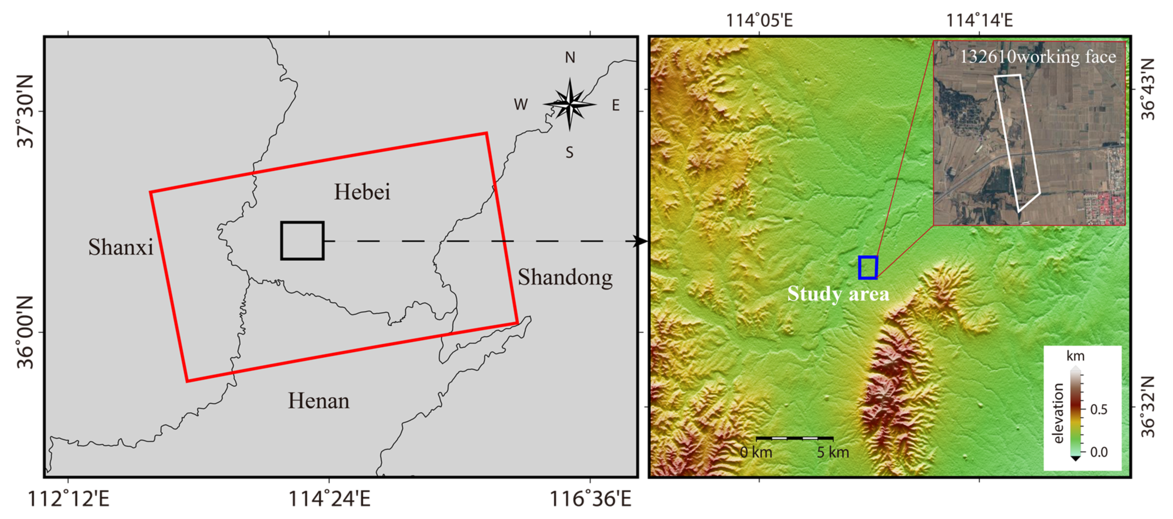
3.2.1. Study Area

Fengfeng coalfield is located in the southwest of Handan City, Hebei Province, China. The fold that controls the overall morphology and structure of the mining area is the Gushan–Zishan anticline; the Zishan anticline in the northern section has an axis of NNE and the Gushan anticline in the southern section has an axis close to SN [35]. The Gushan–Zishan anticline divides the mine into two parts, the eastern monoclinic and the western syncline [36]. The coal-bearing strata of the Fengfeng mining area belong to the Permo-Carboniferous, and they include six to seven mineable coal seams [37]. The Shanxi Formation of the Permian is mainly composed of siltstone, fine gray sandstone, and coal seams, with one mineable coal seam [35]. The Taiyuan Formation of the Carboniferous is mainly composed of gray to dark gray siltstone, sandstone, limestone, and coal seams, with five to six mineable coal seams [35]. Long-term and large-scale coal mining has resulted in a large number of abandoned underground goafs that have caused many related disasters [38]. Therefore, the accurate determination of these unknown old goafs can protect people’s lives and property and allow sustainable development of the mining area. In this study, we selected the surface subsidence area caused by mining the 132,610 working face (the white polygon in Figure 5) as the study area. From the literature [28], the coal seam mining height is 4.5 m, the boundary length is 319 m, the boundary width is 165 m, the dip angle is 31°, the mining direction angle is 169°, and the average mining depth is 774 m.

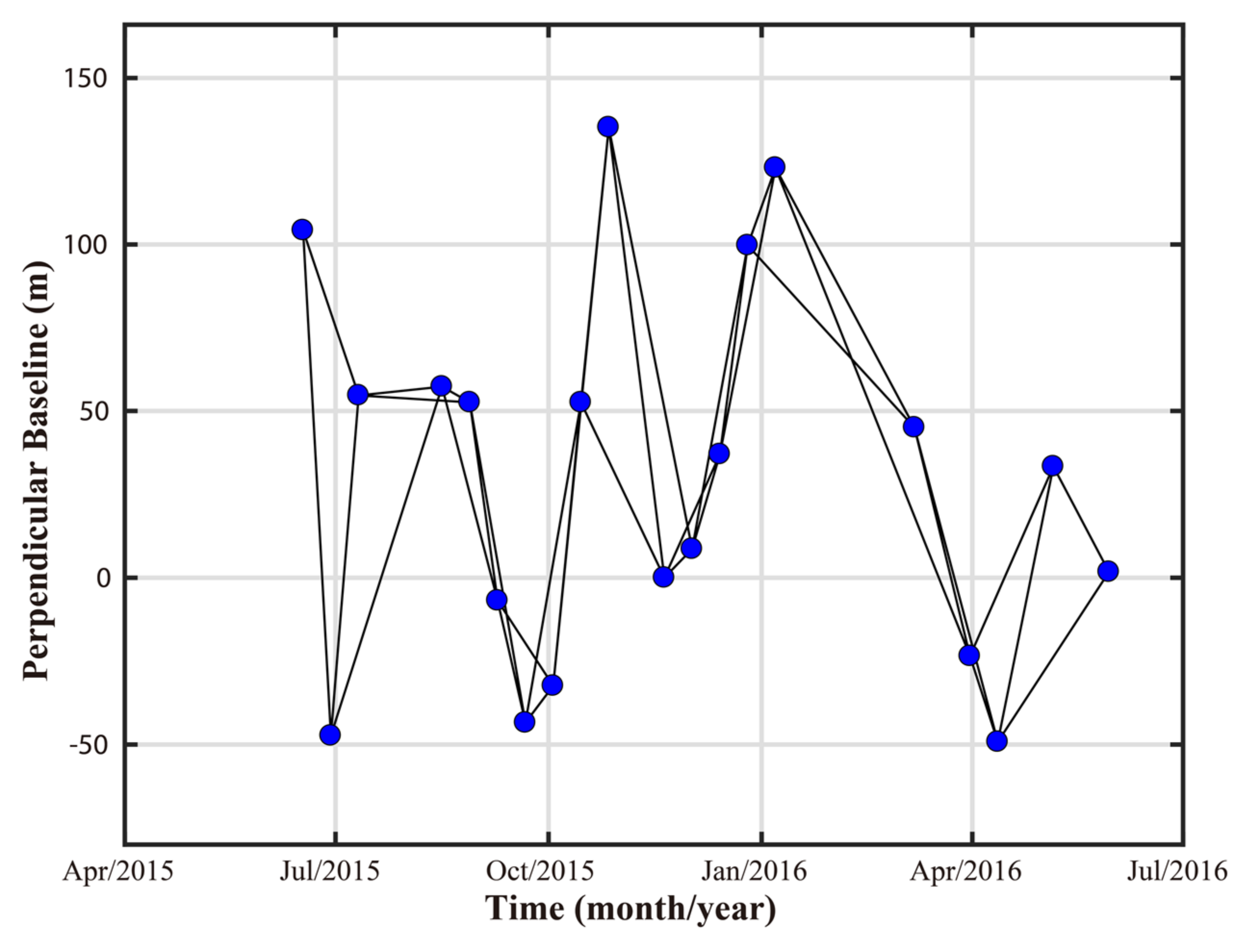
3.2.2. SAR Data Sets and InSAR Processing

Twenty C-band Sentinel-1A images covering the study area were selected to monitor the surface deformation. The basic parameters of the Sentinel-1A data set were shown in Table 1. These images were acquired from 17 June 2015 to 30 May 2016. However, the actual goaf parameters represent the mining information from 15 June 2015 to 5 March 2016. We chose the cumulative deformation from 17 June 2015 to 7 March 2016 as the InSAR observation data to participate in the inversion of the goaf parameters. The acquisition time interval was largely consistent; thus, we considered the actual goaf parameters to still be applicable. The surface deformation caused by mining develops rapidly and has a large magnitude. Therefore, we chose the two-connection network construction method to reduce the impact of time decoherence. As shown in Figure 6, a total of 37 interferometric pairs were selected.
In order to obtain a reliable cumulative deformation caused by the mining of the 132,610 working face, we performed SBAS-InSAR processing [39]. GAMMA software was used to process the selected interference pairs. First, we used a network-based method [40] for image registration. Then, the DEM data of SRTM 1 arc second (30 m) were applied to remove the topographic phases of the interferograms, and we performed a 5 × 1 multi-look operation on the range and azimuth directions to obtain rectangular pixels. Third, the adaptive filter based on the local fringe spectrum [41] was used to further suppress phase noise in the interferograms and generate filtered coherence maps. Afterwards, we masked the points with coherence less than 0.2 and used the minimum cost flow unwrapping method [42] to calculate the ambiguity of the differential interferometric phases. Finally, a polynomial model [43,44] was selected to eliminate the residual phase ramps caused by the atmospheric or baseline modeling error in the differential interferograms. Subsequently, we performed spatio-temporal filtering to remove atmospheric delay components. The cumulative deformation sequence from 17 June 2015 to 7 March 2016 is shown in Figure 7. Because the coal roof is composed of limestone and siltstone, and the mining depth is large (an average of 774 m), continuous deformation of the surface was caused. This was consistent with the time series deformation shown in Figure 7, which proved the accuracy of the InSAR monitoring results from the side.

4. Results

4.1. Simulated Experiment Results

4.1.1. Inversion of Goaf Parameters

Based on the simulation of ground displacement, the inversion of goaf parameters was conducted. We first constructed the functional relationship between the simulated LOS deformation and the geometric parameters of the goaf. Subsequently, the proposed cross-iteration method was used to estimate the geometric parameters of the goaf. The improved GA was used to retrieve unknown parameters in the cross-iteration processing. More specifically, we repeated the GA for 100 times, with a population size of 100, cross fraction of 0.95, and maximum generations of 500. After eliminating gross errors, the final results were obtained by weighting the remaining solutions with the reciprocal of the fitness. It was noteworthy that the empirical values of the subsidence factor q , the horizontal displacement constant b , and the tangent of major influence angle tan β needed to be determined in advance. Since the main lithology of the overlying rock in the simulated goaf was medium-hard, the initial model parameters were obtained based on [45], i.e., q 0 = 0.72 , b 0 = 0.23 , tan β 0 = 2.1 . In the cross-iteration procedure, the value ranges of the parameters were fixed. The value range of each parameter was determined by [45], the common value range and the geometric characteristics of the LOS deformation basin.

4.1.2. Accuracy Evaluation

To visually show the effect of the proposed method on the spatial positioning of the goaf, the simulated underground goaf and the positioning result are depicted in a three-dimensional space, as shown by the black and purple rectangles in Figure 8. It is easy to see that the shapes of the two goafs are similar, but the average mining depth from the inversion is greater than the simulated average mining depth. We projected the two goafs onto a two-dimensional plane. It can be seen from Figure 4 that the gap between the two is not obvious, and they roughly coincide with each other.
To quantitatively evaluate the inversion accuracy of the goaf, we calculated the absolute error and relative error between the inverted and simulated geometric parameters of the goaf (see Table 2). It can be seen that the maximum absolute error was −44.6 m, and the minimum absolute error was 0.03°. There was a significant difference between the absolute error of each parameter. The main reason is that the magnitudes and dimensions of the parameters were not exactly the same, making it difficult for the absolute error to meet the overall requirements for accuracy evaluation. Since the relative error ignores the unit, the accuracy of the parameters can be evaluated uniformly. Table 2 shows that the relative error of goaf parameters was concentrated between 0.0% and 8.9%, and the average relative error was 1.5%. This indicates that the inversion accuracy of the goaf parameters was high, which further proves the reliability of the proposed method.

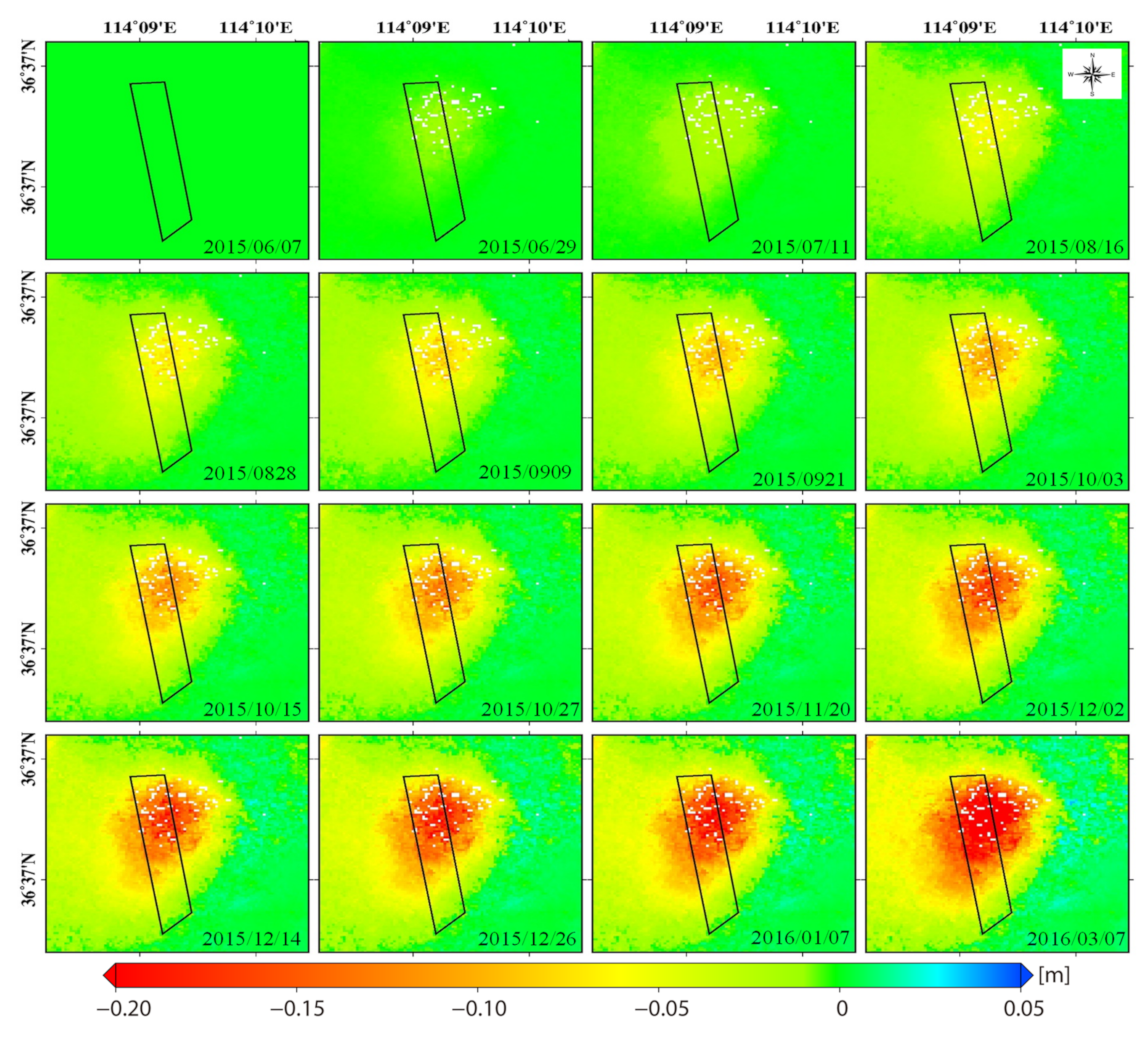
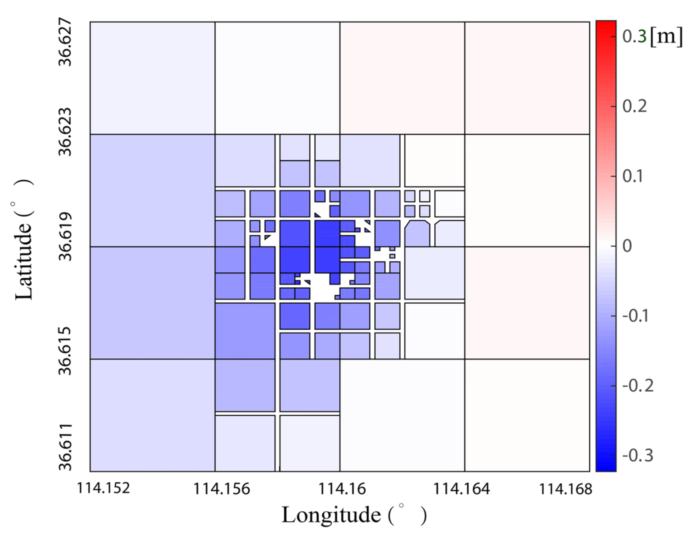
4.2. Real Data Experiment Results

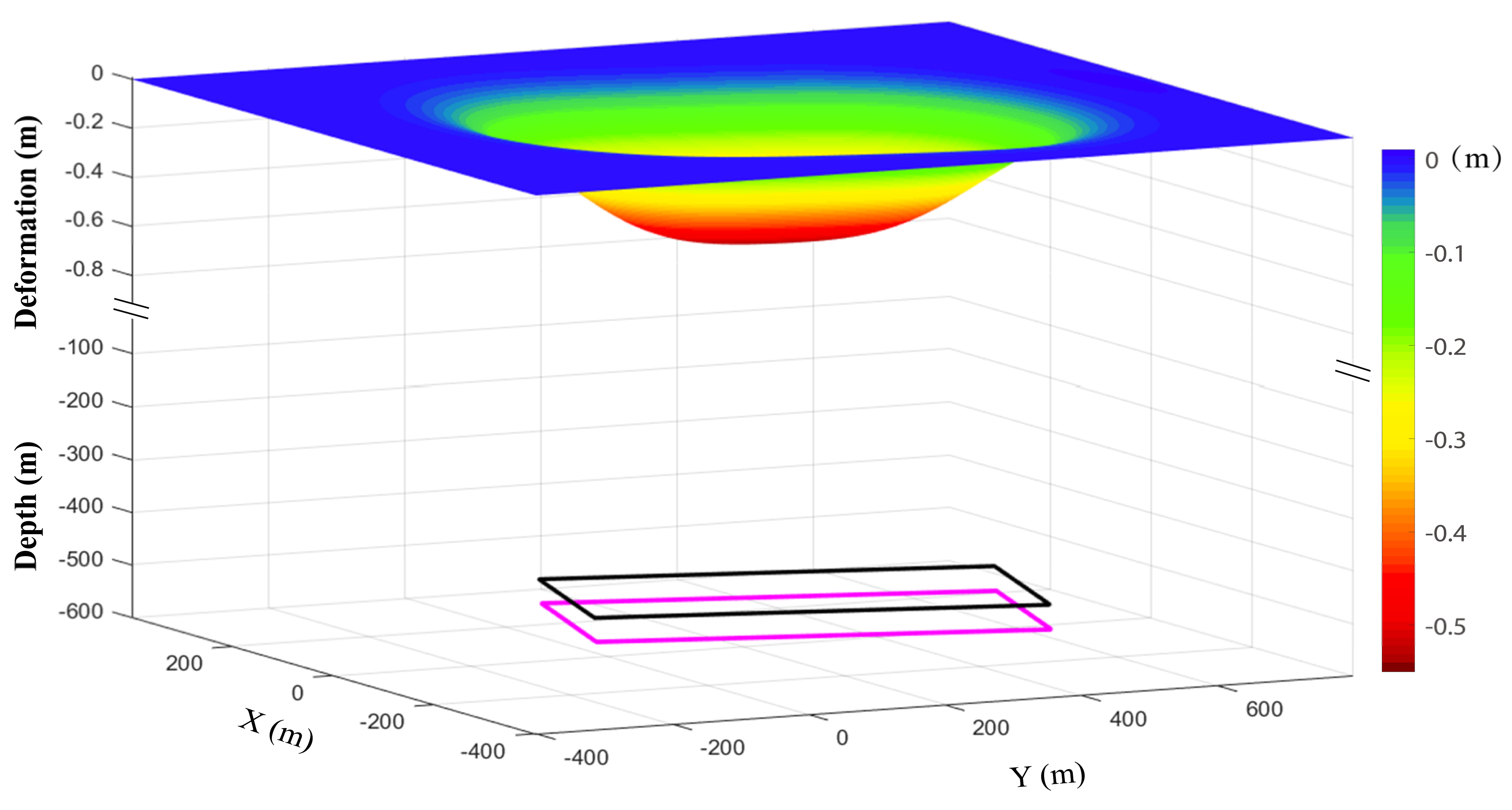
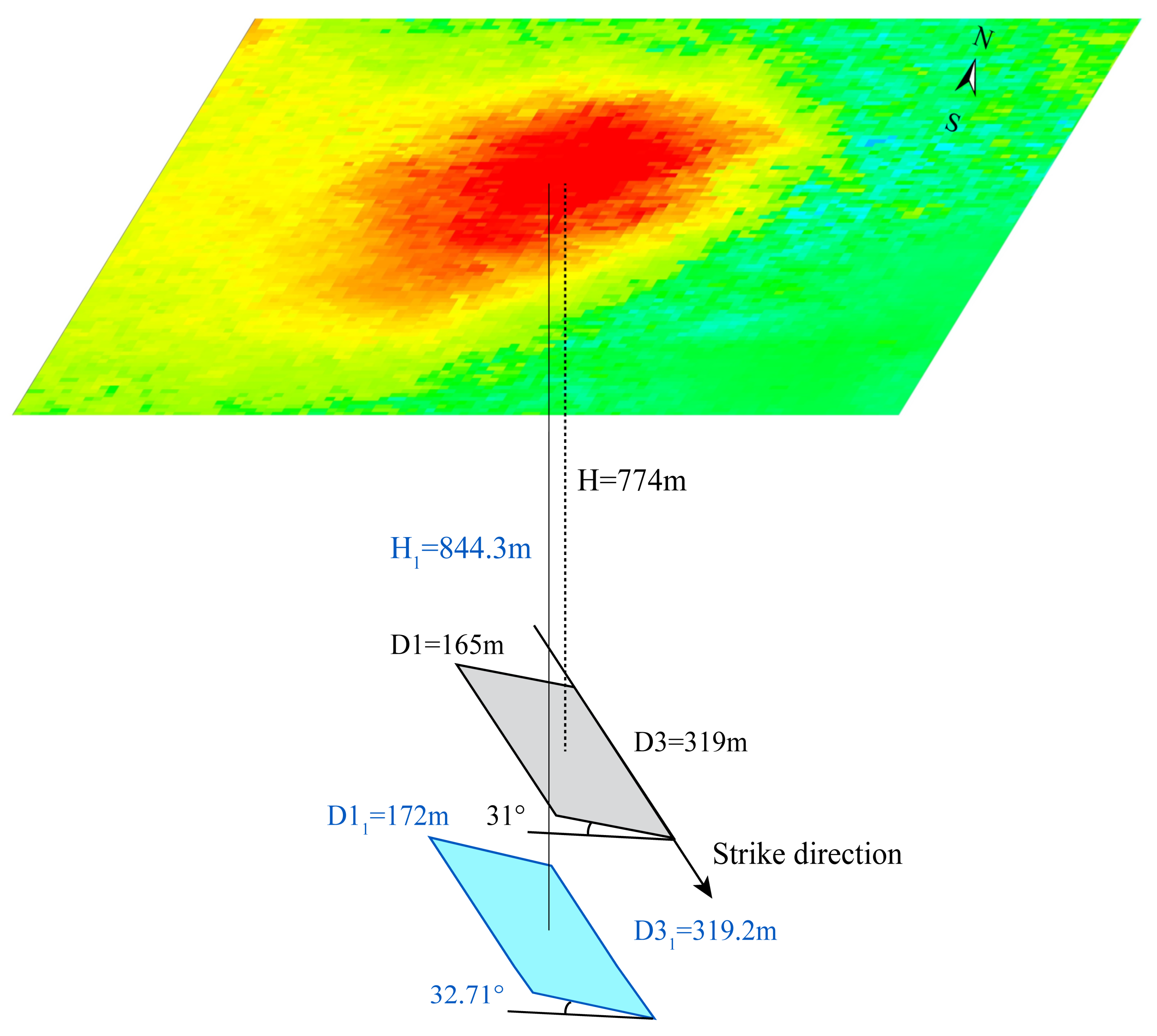
4.2.1. Inversion of Goaf Parameters

According to Equation (8), the construction of the function model needed to determine the local coordinates of the InSAR monitoring deformation. The ground resolution of the geocoded deformation data was 14.324 m × 15.286 m. Therefore, we chose the latitude and longitude of the center of the pixel as the geographic coordinates of the deformation data and converted them to geodetic coordinates. Then, the geodetic coordinates were converted to local coordinates by determining the origin geodetic coordinates and azimuth angle of mining direction. In the cross-iteration process, the local coordinates of the LOS deformation point changed with the iteration of the origin geodetic coordinates and azimuth angle of mining direction.
In this experiment, we used the adaptive quadtree subsampling method to process deformation points. The calculated LOS deformation after adaptive quadtree subsampling is shown in Figure 9. Before the cross-iteration, the empirical values of the three initial model parameters were determined by [45], i.e., q 0 = 0.6 , b 0 = 0.3 , tan β 0 = 1.95 . According to the subsampling LOS deformation data and the initial model parameters, the proposed method was used to invert the geometric parameters of the underground goaf. We used the improved GA to retrieve unknown parameters in the cross-iteration processing. In each iteration, we repeated the GA for 100 times, with a population size of 100, cross fraction of 0.95, and maximum generations of 500. The results are shown in Table 3.

4.2.2. Results and Accuracy Evaluation

We comprehensively analyze the reliability of the cross-iteration method from two perspectives. First, we drew the underground goafs in Figure 10 based on the inverted and actual geometric parameters of the goaf to qualitatively evaluate the positioning results. As is shown in Figure 10, the inverted goaf is not located in the center of the surface subsidence basin but is biased towards the side of the largest sinking point. This is consistent with the general rule of mining subsidence.
Then, we respectively calculated the relative error and absolute error between the inversion value and the measured value of the goaf parameters to quantitatively test the effect of the cross-iteration method. Due to the lack of complete measured data, we did not perform precision analysis on the geodetic coordinate of the origin X 0 = 4,054,325 m , Y 0 = 514,206 m obtained from the inversion. In Table 3, the maximum relative error is 10.7% of the coal seam mining height m . From the perspective of absolute error, the coal seam mining height was only overestimated by about 0.48 m. In a comprehensive consideration, the accuracy of the coal seam mining height was acceptable. The relative error of the average mining depth was 9.1%, similar to the result of the simulation experiment. Furthermore, the difference between the inverted values and measured values of the remaining goaf parameters was small. The average relative error of the six parameters of the goaf, shown in Table 3, was 5.1%, which meets the actual requirements for the location of the goaf. Then, we compared the goaf parameters obtained by the proposed method with those obtained by Xia et al. [28] to further verify the reliability of the cross-iteration method. It can be seen in Table 3 that the geometric parameters of the goaf, except for the average mining depth, have a higher accuracy. The sources of the errors in the inverted geometric parameters of the goaf are discussed in Section 4.3.

4.3. Sensitivity Analysis of Parameters Estimation

4.3.1. Impact of the Cross-Iteration Method

The cross-iteration method uses iteration to improve the accuracy of parameter inversion. Therefore, we first analyzed the impact of iteration on the results. We compared the accuracy of iterative and non-iterative inversion results in real experiments. As shown in Table 3 and Table 4, the absolute and relative errors of the inversion parameters without iteration have increased significantly. The average relative error of the six parameters of the goaf increased from 5.1% to 15.5%. The inversion results show that cross-iteration can improve the accuracy of the goaf parameters.
Simulation experiments can independently verify the influence of each impact condition on the results. Hence, simulation experiments can be designed to better test the performance of the cross-iteration method. We choose the simulated goaf described in Section 3.1, and assumed the PIM model parameters, i.e., q = 0.6 , b = 0.3 , tan β = 2.0 , ω = 82.2 , S 3 = 30 , S 1 = 30 . Subsequently, we predicted the surface LOS deformation by Equation (8). We constructed the functional relationship between the predicted LOS deformation and the PIM model and used the initial model parameters to invert the geometric parameters of the underground goaf. The results obtained by the cross-iteration method are listed in Table 5. In order to verify the impact of the cross-iteration method, we calculated the relative error and absolute error of each geometric parameter of the goaf.
The accuracy of this experiment can be evaluated according to the magnitude and error of the goaf parameters. As shown in Table 5, when there is no error in the LOS deformation, the absolute error and the relative error are both concentrated on the average mining depth H . The larger error proves that the proposed cross-iteration method had the greatest impact on the average mining depth H . Although the accuracy of the average mining depth H was lower than the other goaf parameters, the relative error of H within 10% can meet the requirements of goaf positioning. The remaining geometric parameters of the goaf were roughly in agreement with the simulated values. In addition, the average relative error of the geometric parameters of the goaf was 3%. Therefore, the cross-iteration method obtained the goaf parameters with high overall accuracy, which meets actual engineering needs.

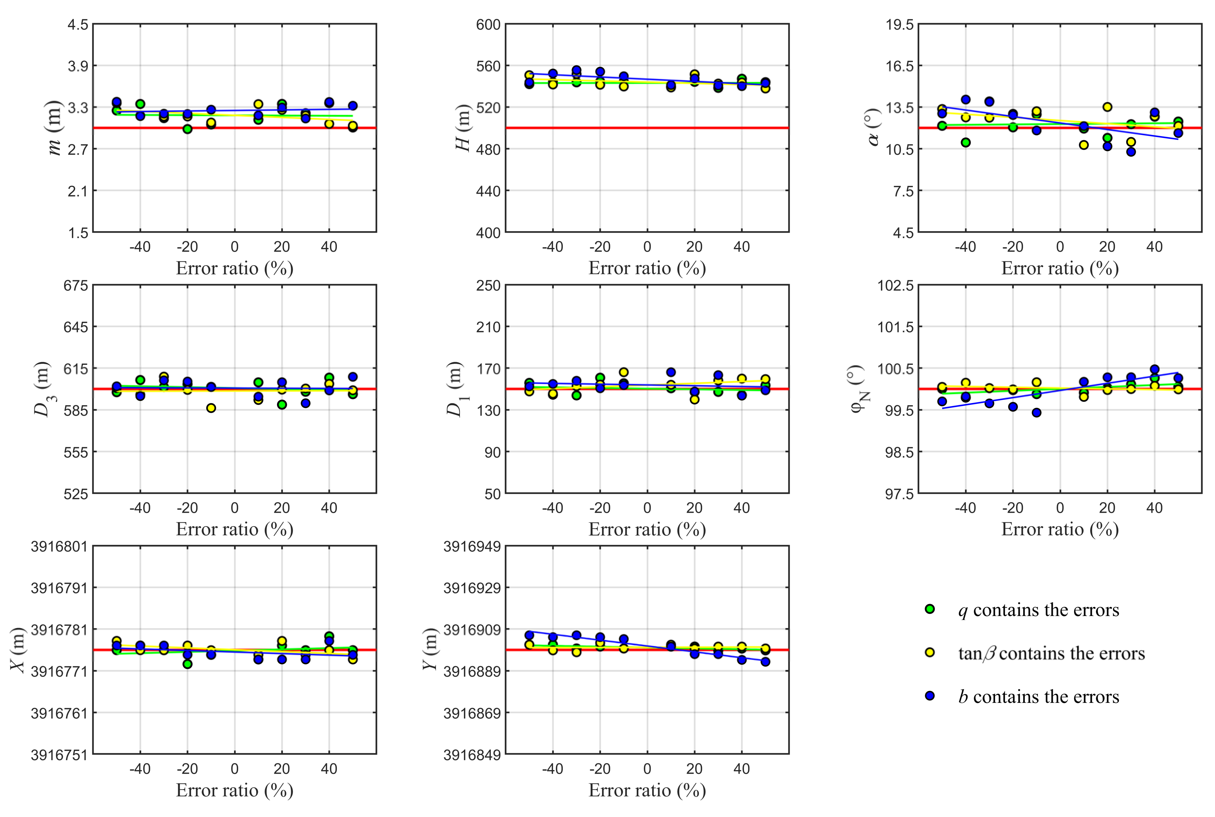
4.3.2. Influence of Deformation Error

InSAR technology solves the displacement vector of the ground object in the LOS direction by separating the interferometric phase [46]. Although we performed the operations as described in Section 3.2.2, the unwrapped deformation phase still contained terrain residuals, orbital errors, unwrapping errors, atmospheric effects, and noise. We tested the influence of LOS deformation error on the positioning results of the goaf through a simulation experiment. We used the predicted LOS deformation described in Section 4.3.1. In order to approximate the actual solution, we added −5 cm to 5 cm random errors to the predicted LOS deformation. Furthermore, we used the precise values of the three initial model parameters to participate in the cross-iteration so that the impact of LOS deformation errors on the positioning results could be effectively evaluated. Afterwards, a cross-iteration experiment was carried out on the LOS deformation with random errors. The inversion results and relative errors of goaf parameters are shown in Table 5. Table 5 shows the accuracy of the coal seam mining height m and dip angle α obtained by the predicted LOS deformation with a decrease in random errors. The absolute error of the two parameters changed from 0.13 to 0.35 and from 0.45 to 1.05, respectively. As the magnitude of the two parameters is small, the absolute error did not clearly change. The relative error of the two parameters changed significantly, increasing by 7.4% and 5%, respectively. Moreover, the accuracy of the remaining goaf parameters was not distinctly affected by the LOS deformation error. In particular, the average mining depth H , which was greatly affected by the cross-iteration method, was not obviously affected by the LOS deformation error. The relative error range of the inverted goaf parameters based on LOS deformation with random errors was 0% to 11.7%, and the average relative error was 4.4%, while the relative error range of the inverted goaf parameters based on error-free LOS deformation was 0% to 8.6%, and the average relative error was 3.0%. The mean relative error and relative error range of the goaf parameters obtained by error-free LOS deformation were both smaller than the former. This shows that the reliability of the goaf parameters was negatively affected by the accuracy of the InSAR-derived deformation. Therefore, using accurate surface LOS deformation can improve the inversion accuracy of the cross-iteration method.

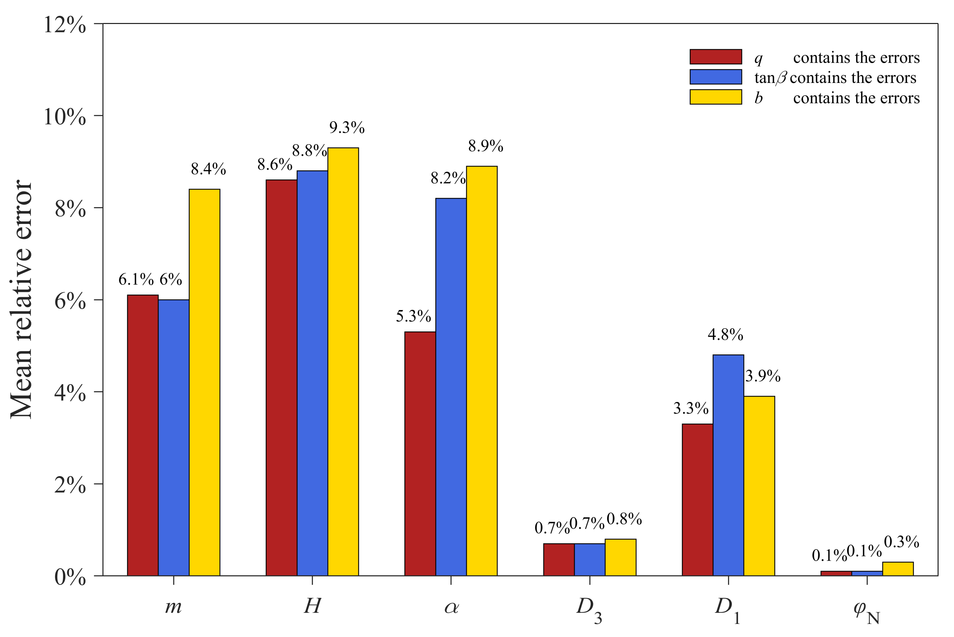
4.3.3. Effect of the Initial Model Parameter Error of the PIM

For goafs that are unknown or lack actual measurement data, the proposed method determines the empirical values of the initial model parameters of the PIM through geological mining conditions, which inevitably contains certain errors. In this section, simulation experiments were conducted to test the influence of model parameter error distribution on the inversion accuracy of goaf parameters. First, we chose the predicted error-free LOS deformation as in Section 4.3.1. Afterwards, we sequentially added -50% to 50% error with an interval of 10% to the three initial model parameters. The detailed method is to select one of the initial model parameters to add −10% to −50% and 10% to 50% error, and the other two parameters do not have an added error. By selecting different initial model parameters that required the addition of errors, a total of 30 sets of parameters can be obtained. Finally, we used the predicted LOS deformation and each set of initial model parameters to perform cross-iteration to invert the geometric parameters of the goaf. The experimental results are shown in Figure 11.
It can be seen from Figure 11 that the accuracy of the initial model parameters of the PIM had no significant effect on the results of the cross-iteration processing. When the error contained in the subsidence factor q and tangent of major influence angle tan β increased, the boundary length D 3 , boundary width D 1 , azimuth angle of mining direction φ N , and geodetic coordinate of the origin X 0 , Y 0 were largely consistent with the simulated values (red line in Figure 11). When the error contained in the horizontal displacement constant b increased, the boundary length D 3 , boundary width D 1 , and origin abscissa of the local plane coordinate system X 0 had no obvious change. However, the accuracy of dip angle α , the origin ordinate of the local plane coordinate system Y 0 , and the azimuth angle of mining direction φ N had a slight downward trend, but there was no significant difference between these two parameters and the simulated values. The calculated average mining depths H were similar to the results in Section 4.3.1. Therefore, we believe that the accuracy of the average mining depth H was not greatly affected by the initial model parameters.
Afterwards, we calculated the average relative error of the goaf parameters, except the geodetic coordinate of the origin X 0 , Y 0 , when different initial model parameters included errors. As shown in Figure 12, the maximum average relative errors of the coal seam mining height m and dip angle α were 8.4% and 8.9%, respectively. We found that the horizontal displacement constant b had a greater impact on the coal seam mining height m than other initial model parameters, and the subsidence factor q and tangent of major influence angle tan β had a greater impact on the dip angle α than the horizontal displacement constant b . Furthermore, we considered the absolute error to more fully analyze the impact of the initial model parameters. When the average relative error was equal to 10%, the coal seam mining height m and dip angle α changed by 0.3 m and 1.2°, respectively. This was sufficient to prove that the relative error of less than 10% did not have much influence on the inversion values of the coal seam mining height m and dip angle α . In addition, the initial model parameters, including errors, had little effect on the geometric parameters of the goaf except for the coal seam mining height m and dip angle α (see Figure 11 and Figure 12).

5. Discussion

5.1. Impact of the Tangent of the Main Influence Angle on the Average Mining Depth

We analyzed the reasons for the large average mining depth error from the principle of the PIM model. Equations (3) and (5) show that the average mining depth H was only used to calculate the main influence radius in strike direction r , i.e., r = H / tan β . Furthermore, we found that the tangent of the major influence angle tan β was overestimated in the cross-iteration processing. If the main influence radius in strike direction r is regarded as a constant, the tangent of the major influence angle tan β has a positive correlation with the average mining depth H . Based on the simulated experiment described in Section 4.3.1, we calculated the ratio of H to tan β in each iteration. The ratios were 251.7, 252.8, and 250.2, respectively. This shows that the ratio of the average mining depth H to the tangent of major influence angle tan β was close to the true value 250, so the assumption that r is a constant was established. Moreover, the magnitude of the two parameters was quite different; a slight fluctuation of the tangent of the major influence angle tan β will cause a large change in the average mining depth H . Therefore, the main reason that the average mining depth H was overestimated is that the tangent of the major influence angle tan β was overestimated. Solving this problem will be the subject of our future research.

5.2. Influence of Subcritical Mining

The ratio of goaf size to mining depth determines the mining degree. When D 3 / H ,   D 1 / H < 1.2 1.4 , the mining degree is subcritical, and when D 3 / H ,   D 1 / H 1.2 1.4 , the mining degree is critical or supercritical, where D 3 and D 1 are the true boundary length and width of the goaf and H is the average mining depth. The ratio of the true boundary length and width of the goaf to the average mining depth in the real experiment is 0.4 and 0.2, respectively. This shows that the mining degree of the 132610 working face is subcritical in the strike and dip directions. The PIM model generally overestimates the 3D surface deformation induced by subcritical mining, because the subsidence factor q for subcritical mining is smaller than the subsidence factor under the critical or supercritical mining. As analyzed in Section 4.3.3, the increase of the subsidence factor has no obvious effect on the geometric parameters of the goaf. Therefore, subcritical mining is probably not the main factor affecting the accuracy of goaf parameters. The results of the real experiment roughly conform to this point of view.

6. Conclusions

This paper proposes a cross-iteration method to determine the spatial location of the underground goaf. The proposed method reduces the required PIM model parameters to three and does not significantly depend on their accuracy. We verified the reliability of the proposed method through experiments. The average relative errors between the geometric parameters of the goaf inverted by the simulation experiment and the real experiment and the real value were 1.5% and 5.1%, respectively.
Analyzing the influence of various factors on the inverted goaf parameters, it was found that the cross-iteration method was the main reason for the overestimation of the average mining depth, but the overestimated value generally did not exceed 10% of the true value. The deformation error monitored by InSAR caused a negative impact on the goaf positioning results, thus ensuring that the accuracy of the InSAR monitoring can improve the accuracy of the goaf positioning. Furthermore, the main reason for the overestimation of mining thickness and coal seam dip in real experiments and simulation experiments may be that the LOS deformation and initial model parameters contained errors, but the overestimated values were not significant. However, there was no obvious linear correlation between the magnitude of the error included in the initial PIM model parameters and the accuracy of the geometric parameters of the goaf. In addition, we should also consider the inapplicability of the PIM model in subcritical mining, which may also be one of the reasons that affect the positioning accuracy of the goaf. Therefore, the improvement of the cross-iteration method and the consideration of the impact of subcritical mining will be the main directions of our future research.

Author Contributions

Conceptualization, W.Z. and J.S.; data curation, W.Z.; formal analysis, W.Z. and Y.Z.; funding acquisition, B.X.; investigation, W.Z. and H.Y.; methodology, W.Z. and J.S.; supervision, J.S. and H.Y.; writing—original draft, W.Z.; writing—review and editing, all authors. All authors have read and agreed to the published version of the manuscript.

Funding

This work was partly supported by the National Key Research and Development Program of China (No. 2018YFC1505403), the National Natural Science Foundation of China (No. 41804008), and the National Science Fund for Distinguished Young Scholars (No. 41925016).

Institutional Review Board Statement

Not applicable.

Informed Consent Statement

Not applicable.

Data Availability Statement

The Sentinel-1 data presented in this study are openly available in ESA/Copernicus at https://scihub.copernicus.eu (accessed on 2 August 2021). The SRTM data presented in this study are openly available in the National Aeronautics and Space Administration (NASA, United States). The measured data of the goaf presented in this study are available in Xia, Y.; Wang, Y. InSAR- and PIM-Based Inclined Goaf Determination for Illegal Mining Detection. Remote Sens. 2020, 12, 3884, doi:10.3390/rs12233884.

Acknowledgments

The authors gratefully acknowledge the Sentinel-1 data provided by ESA/Copernicus, and the SRTM data provided by the National Aeronautics and Space Administration (NASA, United States).

Conflicts of Interest

The authors declare no conflict of interest.

References

  1. Xue, G.Q.; Yan, Y.J.; Cheng, J.L. Researches on detection of 3-D underground cave based on TEM technique. Environ. Earth Sci. 2011, 64, 425–430. [Google Scholar] [CrossRef]
  2. Li, Y.; Yang, J.; Li, S. The application of tem and resistivity sounding to the investigation of gob areas near shawu railway. Geophys. Geochem. Explor. 2011, 35, 274–279. [Google Scholar] [CrossRef]
  3. Bishop, I.; Styles, P.; Emsley, S.J.; Ferguson, N.S. The detection of cavities using the microgravity technique: Case histories from mining and karstic environments. Geol. Soc. Lond. Eng. Geol. Spec. Publ. 1997, 12, 153–166. [Google Scholar] [CrossRef]
  4. Gunn, D.A.; Marsh, S.H.; Gibson, A.; Ager, G.J.; Mcmanus, K.B.; Caunt, S.; Culshaw, M.G. Remote thermal IR surveying to detect abandoned mineshafts in former mining areas. Q. J. Eng. Geol. Hydrog. 2008, 41, 357–370. [Google Scholar] [CrossRef]
  5. Bamler, R.; Hartl, P. Synthetic aperture radar interferometry. Inverse Probl. 1998, 14. [Google Scholar] [CrossRef]
  6. Jiang, M.; Monti-Guarnieri, A. Distributed Scatterer Interferometry With the Refinement of Spatiotemporal Coherence. IEEE TRANS. Geosci. Remote 2020, 58, 3987–6977. [Google Scholar] [CrossRef]
  7. Jiang, M.; Ding, X.; Hanssen, R.F.; Malhotra, R.; Chang, L. Fast Statistically Homogeneous Pixel Selection for Covariance Matrix Estimation for Multitemporal InSAR. IEEE Trans. Geosci. Remote 2015, 53, 1213–1224. [Google Scholar] [CrossRef]
  8. Hooper, A. A new method for measuring deformation on volcanoes and other natural terrains using InSAR persistent scatterers. Geophys. Res. Lett. 2004. [Google Scholar] [CrossRef]
  9. Lu, Z.; Dzurisin, D.; Biggs, J.; Wicks, C.; Mcnutt, S. Ground surface deformation patterns, magma supply, and magma storage at Okmok volcano, Alaska, from InSAR analysis: 1. Intereruption deformation, 19970–2008. J. Geophys. Res. Solid Earth 2010, 115. [Google Scholar] [CrossRef] [Green Version]
  10. Wang, S.; Xu, B.; Shan, W.; Shi, J.; Li, Z.; Feng, G. Monitoring the Degradation of Island Permafrost Using Time-Series InSAR Technique: A Case Study of Heihe, China. Sensors 2019, 19, 1364. [Google Scholar] [CrossRef] [PubMed] [Green Version]
  11. Daout, S.; Doin, M.P.; Peltzer, G.; Socquet, A.; Lasserre, C. Large-scale InSAR monitoring of permafrost freeze-thaw cycles on the Tibetan Plateau. Geophys. Res. Lett. 2017, 44, 901–909. [Google Scholar] [CrossRef]
  12. Chen, F.; Lin, H.; Li, Z.; Chen, Q.; Zhou, J. Interaction between permafrost and infrastructure along the Qinghai–Tibet Railway detected via jointly analysis of C- and L-band small baseline SAR interferometry. Remote Sens. Environ. 2012, 123, 532–540. [Google Scholar] [CrossRef]
  13. Zhao, R.; Li, Z.W.; Feng, G.C.; Wang, Q.J.; Hu, J. Monitoring surface deformation over permafrost with an improved SBAS-InSAR algorithm: With emphasis on climatic factors modeling. Remote Sens. Environ. 2016, 184C, 276–287. [Google Scholar] [CrossRef]
  14. Shi, X.; Zhang, L.; Balz, T.; Liao, M. Landslide deformation monitoring using point-like target offset tracking with multi-mode high-resolution TerraSAR-X data. Isprs J. Photogramm. Remote Sens. 2015, 105, 128–140. [Google Scholar] [CrossRef]
  15. Sun, Q.; Zhang, L.; Ding, X.L.; Hu, J.; Li, Z.W.; Zhu, J.J. Slope deformation prior to Zhouqu, China landslide from InSAR time series analysis. Remote Sens. Environ. 2015, 156, 45–57. [Google Scholar] [CrossRef]
  16. Hu, J.; Li, Z.W.; Ding, X.L.; Zhu, J.J.; Zhang, L.; Sun, Q. 3D coseismic Displacement of 2010 Darfield, New Zealand earthquake estimated from multi-aperture InSAR and D-InSAR measurements. J. Geodesy 2012, 86, 1029–1041. [Google Scholar] [CrossRef]
  17. Feng, G.C.; Hetland, E.A.; Ding, X.L.; Li, Z.W.; Lei, Z. Coseismic fault slip of the 2008 Mw 7.9 Wenchuan earthquake estimated from InSAR and GPS measurements. Geophys. Res. Lett. 2010, 37. [Google Scholar] [CrossRef] [Green Version]
  18. Wright, T.; Fielding, E.; Parsons, B. Triggered slip: Observations of the 17 August 1999 Izmit (Turkey) Earthquake using radar interferometry. Geophys. Res. Lett. 2001, 28, 1079–1082. [Google Scholar] [CrossRef]
  19. Xu, W.; Xie, L.; Aoki, Y.; Rivalta, E.; Jónsson, S. Volcano Wide Deformation after the 2017 Erta Ale Dike Intrusion, Ethiopia, Observed with Radar Interferometry. J. Geophys. Res. Solid Earth 2020, 125, e2020JB019562. [Google Scholar] [CrossRef]
  20. Jung, J.; Kim, D.; Palanisamy Vadivel, S.K.; Yun, S. Long-Term Deflection Monitoring for Bridges Using X and C-Band Time-Series SAR Interferometry. Remote Sens. 2019, 11, 1258. [Google Scholar] [CrossRef] [Green Version]
  21. Qin, X.; Liao, M.; Lu, Z.; Yang, M. Structural Health and Stability Assessment of High-Speed Railways via Thermal Dilation Mapping With Time-Series InSAR Analysis. IEEE J. Stars 2017, 10, 2999–3010. [Google Scholar] [CrossRef] [Green Version]
  22. Tosti, F.; Gagliardi, V.; Amico, F.D.; Alani, A.M. Transport infrastructure monitoring by data fusion of GPR and SAR imagery information. Transp. Res. Proc. 2020, 45, 771–778. [Google Scholar] [CrossRef]
  23. Hanssen, R.F. Radar Interferometry Data Interpretation and Error Analysis; Springer Science & Business Media: New York, NY, USA, 2001. [Google Scholar]
  24. Hu, Z.; Ge, L.; Li, X.; Zhang, K.; Zhang, L. An Underground-Mining Detection System Based on DInSAR. IEEE Trans. Geosci. Remote Sens. 2013, 51, 615–625. [Google Scholar] [CrossRef]
  25. Yang, Z.; Li, Z.; Zhu, J.; Yi, H.; Peng, G.; Hu, J.; Wu, L.; Preusse, A.; Wang, Y.; Papst, M. Locating and defining underground goaf caused by coal mining from space-borne SAR interferometry. ISPRS J. Photogramm. Remote Sens. 2018, 135, 112–126. [Google Scholar] [CrossRef]
  26. Leung, T.W.; Chi, K.C.; Troutt, M.D. Application of a mixed simulated annealing-genetic algorithm heuristic for the two-dimensional orthogonal packing problem. Eur. J. Oper. Res. 2003, 145, 530–542. [Google Scholar] [CrossRef]
  27. Du, S.; Wang, Y.; Zheng, M.; Zhou, D.; Xia, Y. Goaf Locating Based on InSAR and Probability Integration Method. Remote Sens. 2019, 11, 812. [Google Scholar] [CrossRef] [Green Version]
  28. Xia, Y.; Wang, Y. InSAR- and PIM-Based Inclined Goaf Determination for Illegal Mining Detection. Remote Sens. 2020, 12, 3884. [Google Scholar] [CrossRef]
  29. Litwiniszyn, J. Application of the equation of stochastic processes to mechanics of loose bodies. Arch. Mech. 1956, 8, 393–411. [Google Scholar]
  30. Liu, B.; Liao, G. Basic Law of Ground Surface Movement Due to Coal Mining; The Industrial Press of China: Beijing, China, 1965. [Google Scholar]
  31. He, G.; Yang, L.; Ling, G. Mining Subsidence Engineering; Press of China University of Mining and Technology: Xuzhou, China, 1991. [Google Scholar]
  32. Yang, Z.F.; Li, Z.W.; Zhu, J.J.; Hu, J.; Wang, Y.J.; Chen, G.L. InSAR-Based Model Parameter Estimation of Probability Integral Method and Its Application for Predicting Mining-Induced Horizontal and Vertical Displacements. IEEE Trans. Geosci. Remote. Sens. 2016, 54, 4818–4832. [Google Scholar] [CrossRef]
  33. Bagnardi, M.; Hooper, A. Inversion of Surface Deformation Data for Rapid Estimates of Source Parameters and Uncertainties: A Bayesian Approach. Geochem. Geophy. Geosyst. 2018, 19, 2194–2211. [Google Scholar] [CrossRef]
  34. Decriem, J.; Árnadóttir, T.; Hooper, A.; Geirsson, H.; Sigmundsson, F.; Keiding, M.; Ófeigsson, B.G.; Hreinsdóttir, S.; Einarsson, P.; Lafemina, P. The 2008 May 29 earthquake doublet in SW Iceland. Geophys. J. Int. 2010, 181, 1128–1146. [Google Scholar] [CrossRef] [Green Version]
  35. WANG, S.; ZUO, M.; KONG, Q.; ZHANG, N. Study on CBM Geological Features and Exploitation, Utilization in Fengfeng Mining Area. Coal Geol. China 2020, 32, 14–20. [Google Scholar] [CrossRef]
  36. Cao, D.; Zhan, W.; Zhang, J.; Yang, S.; Zhang, L.; Fan, H.; Huang, P.; Qiao, J.; Liu, D.; Chang, M. Neotectonic character of Handan-Fengfeng mining area and its signifficance for coal resource exploitation. J. China Coal Soc. 2007, 32, 141–145. [Google Scholar]
  37. He, J.; Zhai, P.; Jing, F. Fengfeng Coalfield Gas Occurrence Regularity and Influence Factors. Proc. Eng. 2011, 26, 1511–1516. [Google Scholar] [CrossRef] [Green Version]
  38. Diao, X.; Wu, K.; Hu, D.; Li, L.; Zhou, D. Combining differential SAR interferometry and the probability integral method for three-dimensional deformation monitoring of mining areas. Int. J. Remote Sens. 2016, 37, 5196–5212. [Google Scholar] [CrossRef]
  39. Berardino, P.; Fornaro, G.; Lanari, R.; Sansosti, E. A New Algorithm for Surface Deformation Monitoring Based on Small Baseline Differential SAR Interferograms. IEEE Trans. Geosci. Remote. Sens. 2002, 40, 2375–2383. [Google Scholar] [CrossRef] [Green Version]
  40. Xu, B.; Li, Z.; Zhu, Y.; Shi, J.; Feng, G. Kinematic Coregistration of Sentinel-1 TOPSAR Images Based on Sequential Least Squares Adjustment. IEEE J. Stars 2020, 13, 3083–3093. [Google Scholar] [CrossRef]
  41. Goldstein, R.M.; Werner, C.L. Radar interferogram filtering for geophysical applications. Geophys. Res. Lett. 1998, 25, 4035–4038. [Google Scholar] [CrossRef] [Green Version]
  42. Chen, C.W.; Zebker, H.A. Two-dimensional phase unwrapping with use of statistical models for cost functions in nonlinear optimization. J. Opt. Soc. Am. A 2001, 18, 338–351. [Google Scholar] [CrossRef] [PubMed] [Green Version]
  43. Xu, B.; Li, Z.W.; Wang, Q.J.; Jiang, M. A Refined Strategy for Removing Composite Errors of SAR Interferogram. IEEE Geosci. Remote Sens. Lett. 2014, 11, 143–147. [Google Scholar] [CrossRef]
  44. Amelung, F.; Yun, S.H.; Walter, T.R.; Segall, P.; Kim, S.W. Stress Control of Deep Rift Intrusion at Mauna Loa Volcano, Hawaii. Science 2007, 316, 1026–1030. [Google Scholar] [CrossRef] [PubMed]
  45. Bureau, C.I.S. Regulations for Coal Pillar Setting and Coal Pressure Mining in Buildings, Water Bodies, Railways and Main Roadways; China Coal Industry Publishing House: Beijing, China, 2000. [Google Scholar]
  46. Massonnet, D.; Rossi, M.; Carmona, C.; Adragna, F.; Peltzer, G.; Feigl, K.; Rabaute, T. The displacement field of the Landers earthquake mapped by radar interferometry. Nature 1993, 364, 138–142. [Google Scholar] [CrossRef]
Figure 1. Underground goaf (white cuboid) and 3D coordinate system of the PIM model.
Remotesensing 13 03204 g001
Figure 2. (a) Mining subsidence caused by finite extraction in the strike direction; (b) mining subsidence caused by finite extraction in the dip direction.
Remotesensing 13 03204 g002
Figure 3. Flowchart of cross-iteration processing.
Remotesensing 13 03204 g003
Figure 4. The simulated LOS deformation. The black and purple polygons represent the simulated goaf and the location result of the goaf, respectively.
Remotesensing 13 03204 g004
Figure 5. Location of study area (blue polygon) superimposed on the DEM and the coverage area of sentinel-1A image (red polygon) superimposed on the provincial administrative division map. The white polygon represents the 132,610 working surface.
Remotesensing 13 03204 g005
Figure 6. Combination of interferometric pairs. The blue circles represent the SAR images, and the black lines represent the interferometric pairs.
Remotesensing 13 03204 g006
Figure 7. Time series of cumulative deformation. The black polygon represents the 132,610 working surface.
Remotesensing 13 03204 g007
Figure 8. Comparisons between the simulated goaf and the positioning result. The black and purple rectangles represent the simulated goaf and the location result of the goaf, respectively.
Remotesensing 13 03204 g008
Figure 9. LOS deformation of the study area after subsampling.
Remotesensing 13 03204 g009
Figure 10. Comparison between the inversion of the goaf geometry and the actual goaf geometry. The gray polygon is the actual goaf, and the light blue polygon is the inverted goaf.
Remotesensing 13 03204 g010
Figure 11. Goaf parameters retrieved when the initial model parameters of the PIM include errors. The yellow, green, and blue lines are the results of linear fitting; the red line indicates the simulated goaf parameters.
Remotesensing 13 03204 g011
Figure 12. Calculated average relative error of the goaf parameters except origin coordinates of the local plane coordinate system.
Remotesensing 13 03204 g012
Table 1. Basic parameters of the Sentinel-1A dataset.
NumberAcquisition DateAbsolute OrbitPathIncident Angle
117 June 201564124033.7483
229 June 201565874033.7494
311 July 201567624033.7483
416 August 201572874033.7487
528 August 201574624033.7505
69 September 201576374033.7506
721 September 201578124033.7516
83 October 201579874033.7514
915 October 201581624033.7510
1027 October 201583374033.7512
1120 November 201586874033.7566
122 December 201588624033.7566
1314 December 201590374033.7560
1426 December 201592124033.7534
157 January 201693874033.7533
167 March 201610,2624033.7578
1731 March 201610,6124033.7593
1812 April 201610,7874033.7623
196 May 201611,1374033.7629
2030 May 201611,4874033.7560
Table 2. Comparisons between the inverted and simulated geometric parameters of the goaf.
Parameters m α D 3 D 1 φ N H X 0 Y 0
Simulated3 m12°600 m150 m100°500 m3,916,776 m520,899 m
Inverted2.94 m11.97°596.9 m149.8 m100.4°544.6 m3,916,781 m520,896 m
Absolute error−0.06 m−0.03°−3.1 m−0.2 m0.4°44.6 m−5 m3 m
Relative error2.0%0.3%0.5%0.1%0.4%8.9%0.0%0.0%
Table 3. Comparisons between the inverted and measured geometric parameters of the 132,610 working face.
Parameters m α D 3 D 1 φ N H
Measured4.5 m31°319 m165 m169°774 m
Inverted4.98 m32.71°319.2 m172.0 m170.7°844.3 m
Absolute error0.48 m1.71°0.2 m7.0 m1.7°70.3 m
Relative error10.7%5.5%0.0%4.2%1.0%9.1%
Relative error in Xia (2020)-6.45%7.21%16.36%3.55%1.94%
Table 4. Comparisons between the inverted and non-iterative geometric parameters of the 132610 working face.
Parameters m α D 3 D 1 φ N H
Measured4.5 m31°319 m165 m169°774 m
Non-iterative3.69 m41.69°353.8 m182.7 m174.7°894.5 m
Absolute error−0.81 m10.69°34.8 m17.7 m5.7°120.5 m
Relative error18%34.5%10.9%10.7%3.4%15.6%
Table 5. Comparison between the inversion results without errors and with random errors in deformation.
DeformationParameters m α D 3 D 1 φ N H X 0 Y 0
Error-freeInverted3.13 m12.45°600.4 m140.7 m99.9°543.2 m3,916,778 m520,901 m
Absolute error0.13 m0.45°0.4 m−8.3 m−0.1°43.2 m2 m2 m
Relative error4.3%3.8%0.1%5.5%0.1%8.6%0.0%0.0%
Random errorsInverted3.35 m13.05°591.1 m144.1 m100.1°543.8 m3,916,778 m520,904 m
Absolute error0.35 m1.05°−8.9 m−5.9 m0.1°43.8 m2 m5 m
Relative error11.7%8.8%1.5%3.9%0.1%8.8%0.0%0.0%
Publisher’s Note: MDPI stays neutral with regard to jurisdictional claims in published maps and institutional affiliations.

