Article

Real-Time Calibration and Monitoring of Radar Reflectivity on Nationwide Dual-Polarization Weather Radar Network

Weather Radar Center, Korea Meteorological Administration, Seoul 07062, Korea
*
Author to whom correspondence should be addressed.
Remote Sens. 2021, 13(15), 2936; https://doi.org/10.3390/rs13152936
Submission received: 28 June 2021 / Revised: 19 July 2021 / Accepted: 22 July 2021 / Published: 26 July 2021
(This article belongs to the Special Issue Advance of Radar Meteorology and Hydrology)

Abstract

:
Monitoring calibration bias in reflectivity (ZH) in an operational S-band dual-polarization weather radar is the primary requisite for monitoring and prediction (nowcasting) of severe weather and routine weather forecasting using a weather radar network. For this purpose, we combined methods based on self-consistency (SC), ground clutter (GC) monitoring, and intercomparison to monitor the ZH in real time by complementing the limitations of each method. The absolute calibration bias can be calculated based on the SC between dual-polarimetric observations. Unfortunately, because SC is valid for rain echoes, it is impossible to monitor reflectivity during the non-precipitation period. GC monitoring is an alternative method for monitoring changes in calibration bias regardless of weather conditions. The statistics of GC ZH near radar depend on the changes in radar system status, such as antenna pointing and calibration bias. The change in GC ZH relative to the baseline was defined as the relative calibration adjustment (RCA). The calibration bias was estimated from the change in RCA, which was similar to that estimated from the SC. The ZH in the overlapping volume of adjacent radars was compared to verify the homogeneity of ZH over the radar network after applying the calibration bias estimated from the SC. The mean bias between two radars was approximately 0.0 dB after correcting calibration bias. We can conclude that the combined method makes it possible to use radar measurements, which are immune to calibration bias, and to diagnose malfunctioning radar systems as soon as possible.

1. Introduction

Considering the spatial coverage of a single weather radar, the nationwide radar network can enhance the utilization of a weather radar in monitoring severe weather, radar rainfall estimation, hydrometeor classification algorithm, and short-term range forecasting of precipitation. Uniform quality maintenance among the individual radar observations in the network is the primary concern in terms of the utilization of the entire network. A heterogeneous radar network consisting of different frequencies, models, manufacturers, dual-polarization capability, and production years makes it difficult to maintain the same quality of radar data across the network. Even in a homogeneous radar network, establishing a regular radar calibration and monitoring procedure is essential to ensure high-quality data because miscalibration of individual radars results in considerable discrepancies in radar measurements over the network. Moreover, the miscalibration strongly affects the overall performance of network-based operational radar applications, such as nationwide quantitative precipitation estimation (QPE), quantitative precipitation forecasting, and hydrometeor classification algorithm.
Unfortunately, miscalibration of radar reflectivity (ZH) frequently occurs due to malfunctions of radar components and cannot be ignored in terms of supporting 24-h routine weather forecasts. The real-time implementation of the accurate calibration of ZH and its monitoring continues to be challenging despite regular maintenance and inspections (i.e., monthly, quarterly, and annual on-site inspections). Therefore, we aimed to develop an automated technique for real-time monitoring and calibration of ZH for an operational S-band dual-polarization weather radar.
Various calibration approaches have been proposed for ZH; they can be divided into three categories: (1) known reference sources such as the sun, a metal sphere, ground clutter (GC), and self-calibrated signal generator [1,2,3,4,5,6,7], (2) self-consistency (SC) principle between polarimetric observations [8,9,10,11,12,13], and (3) comparison with external instruments such as disdrometer, vertically pointing radar, and space-borne weather radar [12,14,15,16,17,18,19,20,21].
The SC principle is widely utilized for the ZH calibration of operational polarization weather radar because this approach does not require any comparative analysis using other instruments and external signal sources. The calibration bias of ZH can be estimated by calculating the phase-related observations from power-related observations during rain. Unfortunately, it is impossible to monitor the change in calibration bias during the non-precipitation period and snow in the winter season.
The GC, which is an ever-present echo, can be used to monitor changes in calibration bias. The monitoring of radar calibration using GC was first introduced by Rinehart [22]. Silberstein et al. [7] introduced a relative calibration adjustment (RCA) technique to monitor the calibration status of an S-band dual-polarization radar. This technique uses the probability distribution of GC reflectivity (ZC) located near the radar at low elevation angles. Silberstein et al. [7] found that the distribution of ZC can vary owing to the change in precipitation intensity, but the statistics of the ZC are relatively stable. In addition, the RCA technique can be applied to a radar located in significant anomalous propagation (AP) conditions because the statistics of ZC showed no significant change in AP conditions [7]. Wolff et al. [23] developed the RCA technique to monitor NASA’s polarimetric surveillance radar in near-real-time during the Iowa Flood Studies (IFloodS) Global Precipitation Measurements (GPM) field campaign. The RCA changed owing to a subtle change in the elevation angle of the antenna, a malfunctioning modulator, and a change in calibration bias. Hunzinger et al. [24] extended the RCA technique to higher-frequency radars and range–height indicator (RHI) scans, and called it the eRCA technique. The studies mentioned above were commonly limited to a single radar or research radar operated for the field campaign. Therefore, an investigation is required to apply the RCA technique to an operational radar network.
Recently, an integrated method was designed to complement the disadvantages of each technique. Vaccarono et al. [25] developed an online software to monitor the stability of radar calibration using SC, intercalibration, GC calibration, and solar calibration techniques. Louf et al. [26] proposed an integrated method using GC monitoring, comparisons with satellite radar, and SC. Crisolo and Heistermann [27] compared ground radar and spaceborne radar observations to calibrate ground radars, and then used ground radar overlaps to verify the consistency between two ground radars.
In this study, GC monitoring, SC, and intercomparison were combined to monitor the calibration bias in ZH for 10 operational S-band dual-polarization radars operated by the Korea Meteorological Administration (KMA) in real time. The common characteristic of the methods we selected is that all the methods use only radar polarimetric observations, and it has an advantage in terms of operational environment because the three methods only require radar data across the network. Section 2 describes the KMA nationwide radar network, while Section 3 introduces the concept of the combined method and principles, development, and pros and cons of each technique. In Section 4, ZH monitoring based on GC monitoring and SC is described. In addition, the potential of estimating calibration bias from GC monitoring was examined. The homogeneity of ZH over the radar network was also examined by calculating the mean bias between adjacent radars. A summary and conclusion are presented in Section 5.

2. Data

We utilized polarimetric observations from an operational dual-polarization S-band weather radar network operated by the KMA from 1 May to 31 July 2020. The KMA replaced single-polarization radars with dual-polarization radars from 2014 to 2019. The KMA constructed a homogeneous S-band dual-polarization radar network with the same specifications. The KMA’s radar network was mainly installed along the border line and coastal area to support wide network coverage over the Korean Peninsula (Figure 1). The scanning strategy performs a three-dimensional observation consisting of nine elevation angles every 5 min. Table 1 presents the scan strategy of each radar within the KMA network. Three radars (KWK, MYN, and PSN) located at high altitudes (>600 m mean sea level (MSL)) include the negative (−) elevation as the lowest elevation angle. All elevation angles use the dual-PRF mode (5:4) to increase Nyquist velocity to alleviate velocity aliasing. Table 2 shows the specific radar parameters of GSN radar. A long pulse with a pulse width of 2 μs was transmitted at low elevation angles (less than 3°) to improve the sensitivity of polarimetric observations [28], while a short pulse with a pulse width of 1 μs was used at high elevation angles (>3º) to increase the pulse repetition frequency (PRF). The azimuth resolution and bin size were 1.0° and 250 m, respectively, for all elevation angles. To monitor the ZC, unfiltered ZH (ZH before applying the clutter filter in the signal processing procedure such as IIR and GMAP) must be recorded. ZH before quality control process was used for the GC monitoring. The ZH after the quality control process developed by Oh et al. [29] was used for SC and intercomparison among ZH across the network.

3. Methods

3.1. Concept

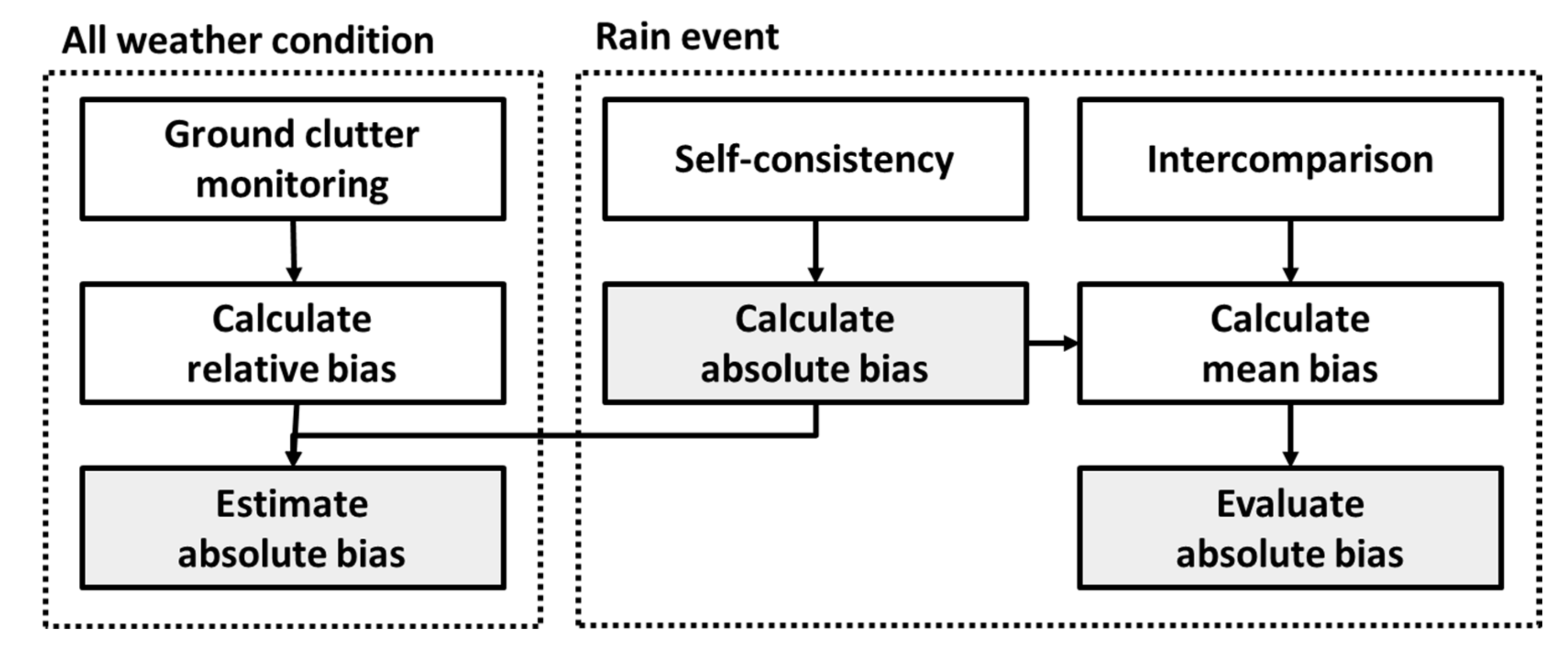
Three techniques (GC monitoring, SC, and intercomparison) were combined for monitoring the calibration status of operational S-band radar ZH in real-time, as shown in Figure 2. The location and intensity of the GC ZH (ZC) near the radar were stationary and not subject to refractivity or beam propagation. In other words, the distance from radar and the returned power from the GC are constant in the radar equation. The only need-to-know factor for radar calibration is the radar constant which aggregates every effect related to the radar system. However, the change in ZC (ΔZC) over time can capture the change in radar system status even if the external source is needed to know the radar constant. Hence, the change in the calibration bias of ZH can be monitored from the ZC, but it is only a relative calibration. The SC method can calculate the absolute calibration bias using polarimetric observations. Unfortunately, it is impossible to monitor ZH during the non-precipitation period because SC is valid for rain echoes. Since the GC is an ever-present echo, the calibration bias can be estimated from the ΔZC and the calibration bias calculated from the SC method regardless of weather conditions. Therefore, the combination of GC monitoring and SC is an effective countermeasure for monitoring the calibration bias of ZH in real-time. In terms of the radar network, a comparison of ZH between adjacent radars can be used to examine the consistency of ZH. If two radars are well calibrated, then the mean bias of ZH is 0.0 dB. The mean bias can determine the calibration bias if one or more radars are well-calibrated over the radar network. Also, the calibration bias estimated from SC can be evaluated by calculating the mean bias of ZH between adjacent radars. It is noted that the combined method can monitor, calculate, and evaluate calibration bias.

3.2. Ground Clutter (GC) Monitoring

The ZC was monitored by calculating the relative calibration adjustment (RCA), which is defined as the change in ZC relative to the baseline. The procedures for calculating RCA were divided into three steps: (1) construction of the GC map (GCM), (2) determination of the baseline, and (3) calculation of the RCA.
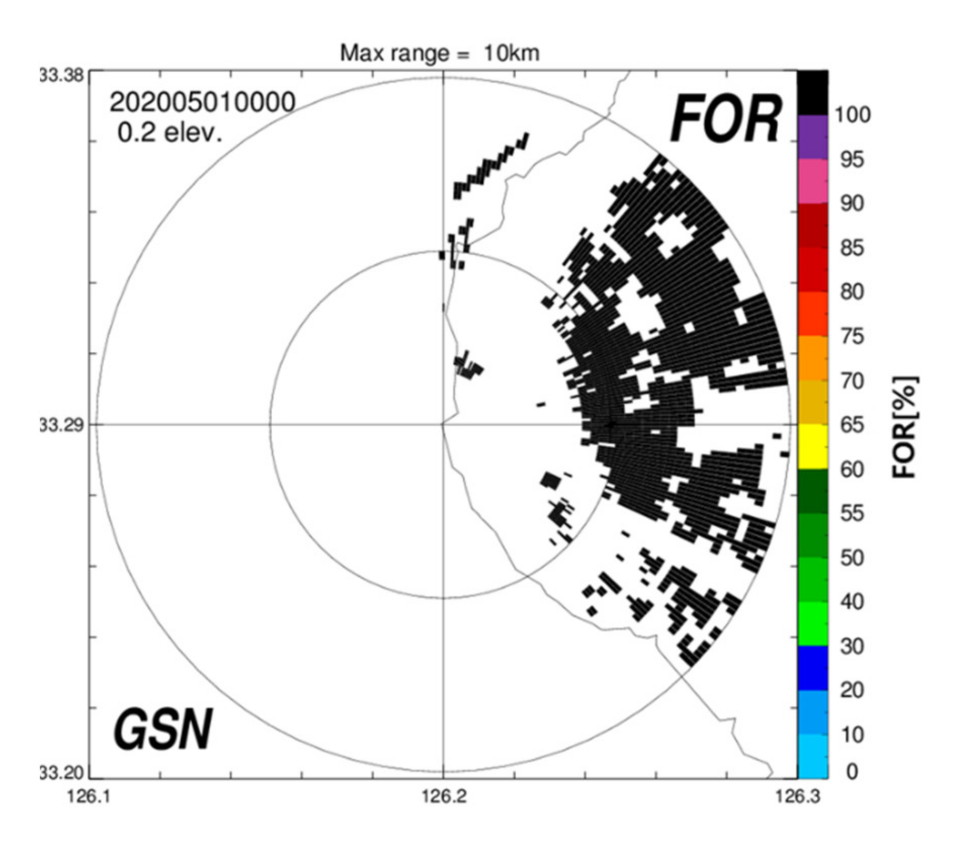
The GCM was constructed by counting the frequency of reflectivity (FOR) over a predefined threshold (50 dBZ) for a short period (an hour) on a clear day. The bin with a FOR of 100% was defined as GC. Wolff et al. [23] accumulated ZH above 55 dBZ during a single precipitation-free day (24 h) and selected the bin with FOR ≥ 50% within 1–5 km range from the radar to minimize AP effects. In this study, a GC above 50 dBZ within a 1–10 km or 1–15 km range from the radar was selected because no sufficient GC above 55 dBZ was captured within a 1–5 km range due to the surrounding geography. The statistics of ZC were stable despite a short period and somewhat far range (will be shown in the next section). We constructed the GCM of individual radar at the first time of the analysis period (0000 KST 1 May 2020). Figure 3 is an example of GCM for GSN radar located at low altitudes and in the western part of Jeju Island. The total number of GCs was 1584 within 1–10 km, and most GCs were in the eastern part of the GSN radar due to the Halla Mountain.
The RCA depends on the baseline. To determine the baseline, the ZC was extracted from the data used to construct the GCM. The 95th (Zbaseline,95th) and 50th percentile (Zbaseline,50th) of ZC were defined as the baseline from the probability distribution of ZC. We determined the baseline using the data when the calibration value was unknown. In other words, the RCA reflects the change in calibration status with respect to a baseline. Therefore, it is important to check the change in RCA, not the absolute value of RCA.
In this study, the hourly RCA was calculated from the ZC statistics. We used hourly RCA to identify the changes in the radar system as quickly as possible and to figure out when the calibration bias changed during the non-precipitation period. The RCA and azimuth and/or elevation slip indicator (dMedian) were calculated using the following equations:
RCA(dB) = Zbaseline,95th − ZC,95th
dMedian = |Zbaseline,50th − ZC,50th|
where ZC,95th and ZC,50th are the 95th and 50th percentiles of ZC, respectively. The Zbaseline,50th, was not used in previous studies [7,23,26]. In this study, the Zbaseline,50th, was used to determine the change in antenna pointing.
To estimate the calibration bias from RCA, the change in RCA (ΔRCA, Equation (3)) was defined as the difference between the most recent RCA (RCArecent) and RCA at the current time (RCAcurrent). The calibration bias (ϵGC) was estimated using the following equations:
ΔRCA(dB) = RCAcurrent − RCAmost recent
ϵGC = ϵSC − ΔRCA
where, ϵSC is the calibration bias estimated from the SC of previous rainfall events.

3.3. Calculation of Calibration Bias in ZH Based on SC Principle

The calibration bias in ZH was calculated by comparing the power-related observations with the phase-related observations. ZH can be contaminated by several error sources, such as bright bands, partial beam blockages, and rainfall attenuation. The following criteria were suggested to avoid the effects of observational error sources.
  • The data from the third to the last elevation angles with a pulse width of 2 μs were selected to minimize the impact of the GC.
  • The contamination by the bright band was removed based on the statistics of the monthly averaged bright band [30] and ρHV.
  • The partial beam blockage region was identified based on beam blockage simulation (BBF). The BBF is calculated by assuming the beam propagation in the standard atmosphere and the Gaussian beam pattern using digital elevation model (DEM) data with a horizontal resolution of 30 m [31,32]. The azimuth angle, where the BBF was greater than 10%, was excluded.
  • The relationship between ZH and specific attenuation (A = 3.348 × 10⁶ ZH0.755) was used to correct the ZH loss caused by rain attenuation [33]. The ZH-A relationship was derived from Precipitation Occurrence Sensor System (POSS) disdrometer data collected at Busan (35.12°N, 129.10°E), South Korea.
  • Azimuth angles containing ZH above 45 dBZ were excluded to avoid the presence of hail.
  • If the mean ZH near the radar was above 30 dBZ, the scan was excluded to avoid wet radome attenuation.
The relationship between ZH and the specific differential phase (ZH = 7.33 × 10⁴ KDP1.1) suggested by Kwon et al. [13] was used. The calculated ΦDPDP_cal) was obtained by accumulating the specific differential phase (KDP) along the radial direction. The measured ΦDPDP_meas) is defined as the change in ΦDP from the start to the end of the rain path. A finite impulse response (FIR) filter was repeatedly applied to reduce the noise in the measured ΦDP. In addition, the rain path was carefully selected. The successive rain segment, where ΦDP is greater than 3°, was selected, and the rain path should be at least 10 km. The calibration bias (εSC) is calculated from the slope (tan θ ) of the ΦDP pairs, as shown in the following equation:
tan θ   = Φ DP_cal Φ DP_meas / Φ DP_meas 2 ε SC ( dB ) = ( 10 × b ) log ( tan θ )
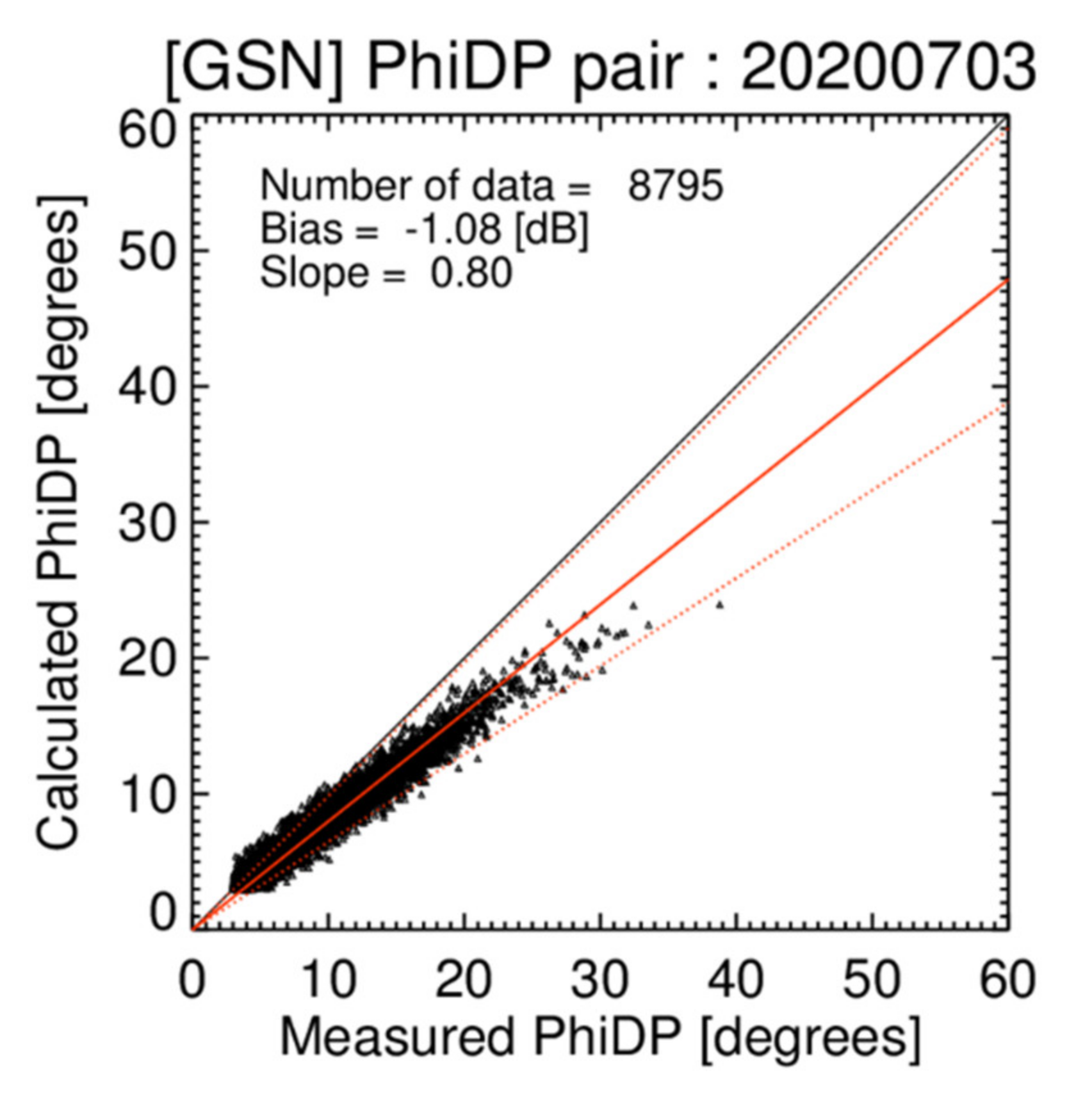
where b is the exponent (=1.1) of the ZH-KDP relationship. A positive calibration bias means that ZH was over-measured, while a negative calibration bias means that ZH was under-measured. Figure 4 shows the scatterplot of ΦDP_cal and ΦDP_meas for the GSN radar on 3 July 2020. The slope (tan θ ) of the ΦDP pairs was 0.80 in Figure 4. In addition, the calibration bias of GSN radar was −1.08 dB for this case.

3.4. Intercomparison

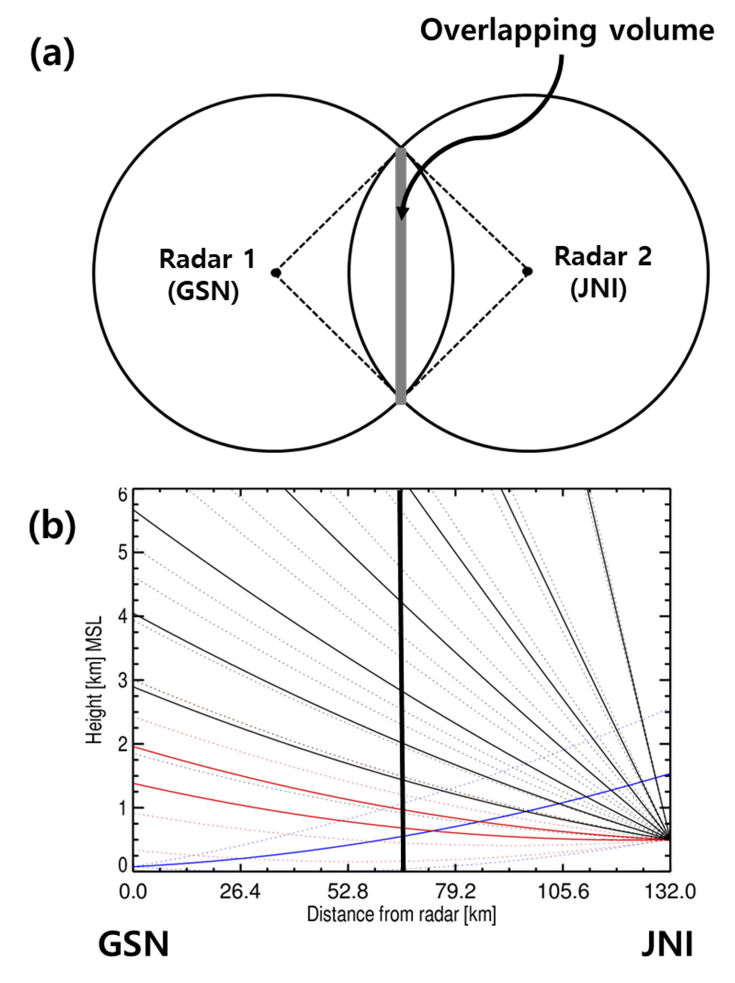
The mean bias between the two radars was calculated to evaluate the homogeneity of the radar network. Figure 5 indicates that the radar bins in geometrical overlapping areas between two radars (overlapping volume) was selected by calculating the height of the radar beam at the center of equidistant from the two radars (thick vertical solid line in Figure 5b). The shadow area in Figure 5a represents the overlapping volume at the equidistance from two radars and the dashed line in Figure 5a represents the range of the azimuth angle for equidistance including overlapping volume. Figure 5b shows an example on how an elevation angle is selected. The solid line represents the height at the center of the beam, while the dotted line represents the height at the top and bottom of the beam. The conditions for matching the overlapping volume are as follows:
  • The difference between the heights at the center of beam is less than 500 m.
  • The center of beam is within volume of beam of each radar.
  • The height at the center of the beam was limited to 0.5 to 3.0 km to select the ZH in the rain region.
  • The range of volume of beam from the radar was limited to 200 km.
The blue solid line and dotted line represents the volume of beam for the first elevation angle of the GSN radar. The volume of beam for elevation angles of the JNI radar, which satisfy the predefined conditions, are shown in red solid and dotted lines. The black solid and dotted lines represent the volume of beam for elevation angles of the JNI radar which do not satisfy the predefined conditions. The two radars with the largest number of overlapping volumes were matched for comparison. The maximum number of overlapping volumes was determined as the maximum number of pairs of ZH between two radars at one time (the rain echoes pass all overlapping volume). The distance and number of overlapping volumes for matched radar pairs are shown in Table 3. Observational errors, such as calibration bias, beam blockage (ΔZH = −10log(1−BBF)), and rain attenuation, were corrected before inter-comparison. The data with a ρHV of more than 0.97 were used to extract ZH for rain echoes. The mean bias was calculated by averaging the difference in ZH in the overlapping volume after excluding the beam where the BBF was greater than 10% to avoid the effect of beam blockage.

4. Results

4.1. Monitoring of the RCA and Calibration Bias

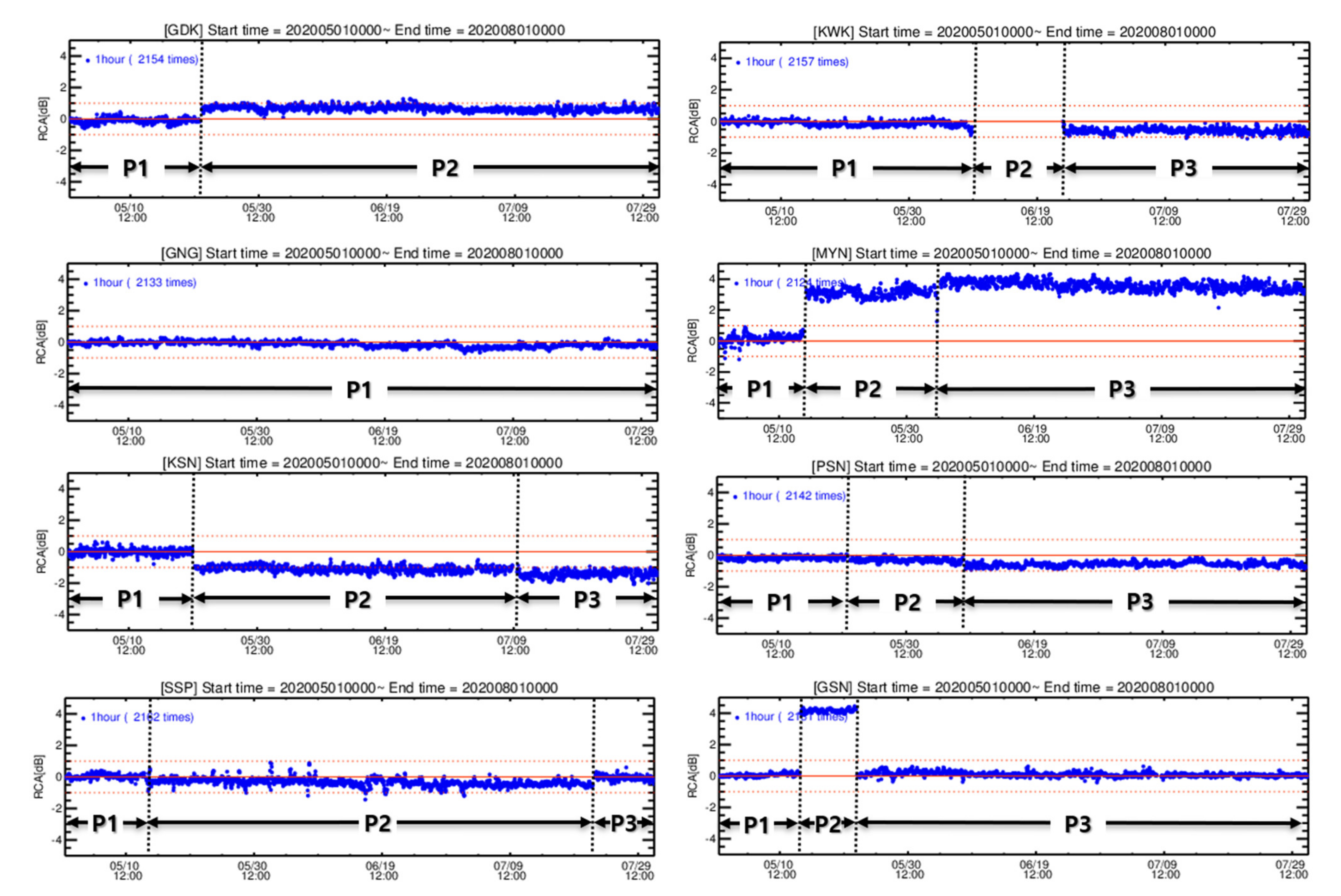
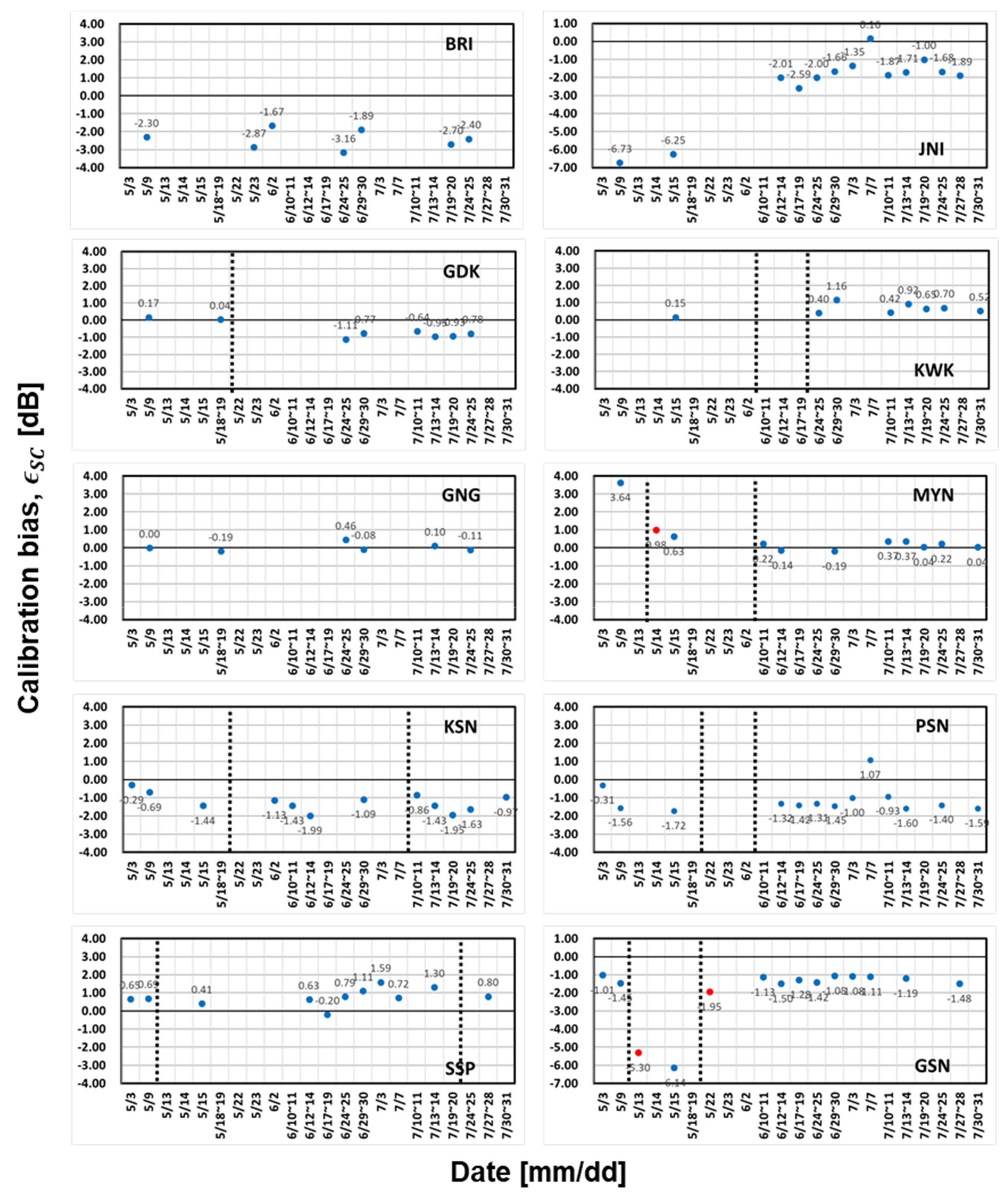
We monitored ZH based on SC and GC monitoring. The RCAs for each radar within the KMA network were calculated to monitor the radar system status, as shown in Figure 6. The BRI and JNI radar on the KMA network were excluded from this analysis. The ZH of BRI radar was recorded with a resolution of 0.5 dBZ due to the data transfer problem related to network capacity during an analysis period. For the JNI radar, there is no GC echo near the radar. The periods (P1, P2, and P3) were divided by considering the change in RCA (ΔRCA). The RCA of the KWK radar during P2 was higher than 5 dB. The mean and standard deviation (STD) of the RCA for each period are shown in Table 4. The STD of RCA for each period was less than 0.3 dB. It was proven that RCA was stable despite the short period for constructing the GCM. The absolute calibration bias calculated based on SC for each radar within the KMA network during the entire period is shown in Figure 7. The εSC (blue dot) and εGC (red dot) were compared when the RCA changed significantly owing to the change in calibration bias.

4.1.1. Well-Calibrated Radar

The RCA of the GNG radar did not change during the entire period. The mean RCA of GNG radar for P1 was −0.14 dB with a STD of 0.16 dB. The εSC was close to 0.0 dB, which indicates that the GNG radar was very well calibrated. In other words, the GNG radar is a good reference for calculating the mean bias between two radars.

4.1.2. Monitor the Antenna Pointing

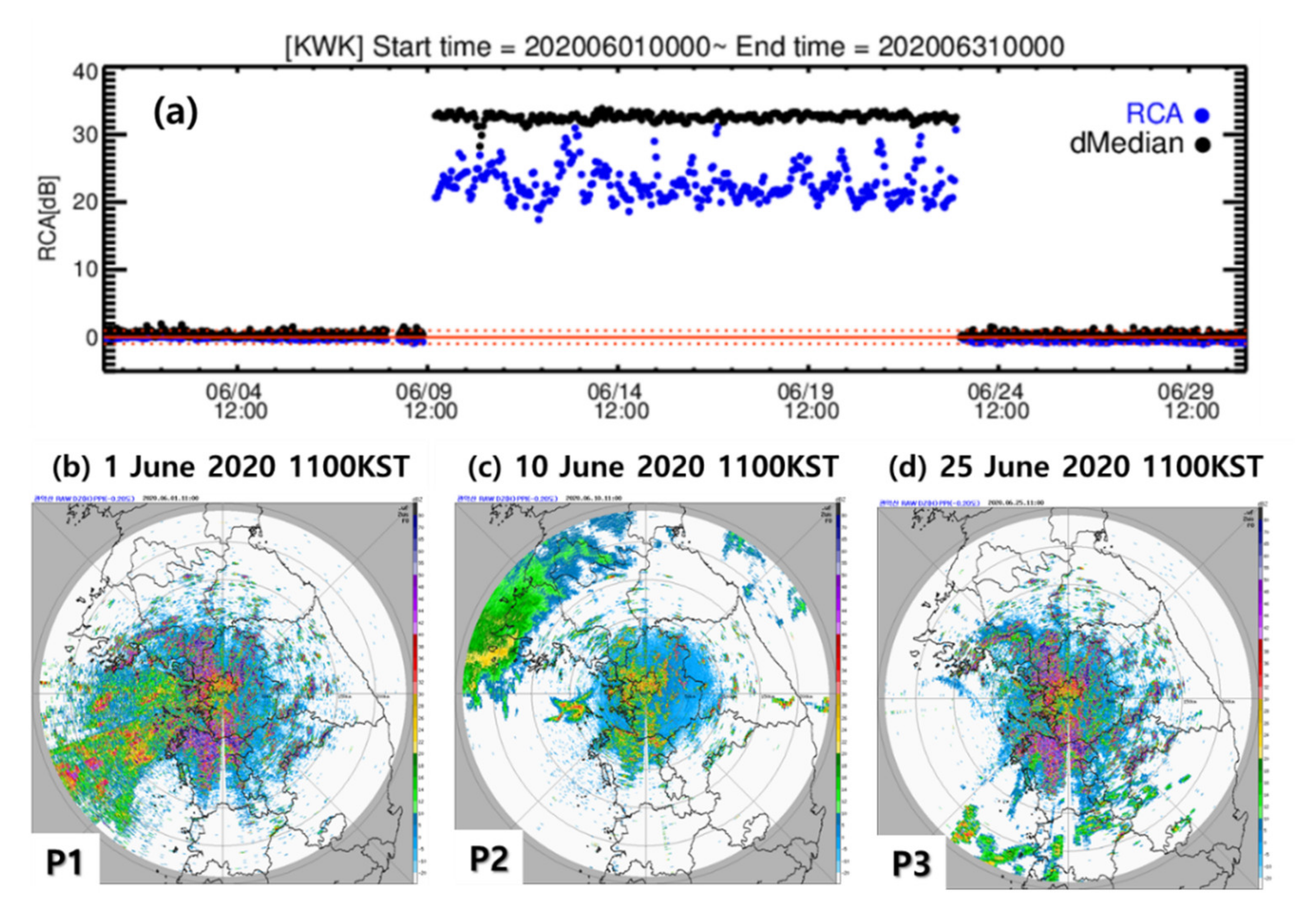
The dMedian reflects the change in the 50th percentile of Zc. The dMedian is more sensitive to change in the distribution of Zc than RCA which reflects the change in the 95th percentile of Zc. So, the dMedian was used to determine the change in antenna pointing. Figure 8 shows the time series of RCA and dMedian for KWK radar from 0000 KST 1 June 2020to 0000 KST on 31 June 2020 (Figure 8a) and PPIs of ZH at an elevation angle of −0.2° of KWK radar at 1 June 2020, 1100 KST (Figure 8b), 10 June 2020, 1100 KST (Figure 8c), and 25 June 2020, 1100 KST (Figure 8d). The number of GCs was significantly reduced during P2. The RCA and dMedian of KWK greatly changed at the end time of P1 due to an elevation angle offset problem. Also, the RCA fluctuations during P2 was considerably larger than those during P1 and P3 due to the pointing problem along the elevation angle. The antenna pointing was reset at the end of P2. The number of GCs in Figure 8d is similar to that in Figure 8b. The RCA difference between P1 (−0.11 dB) and P3 (−0.59 dB) was due to the slight change in the transmitted power.
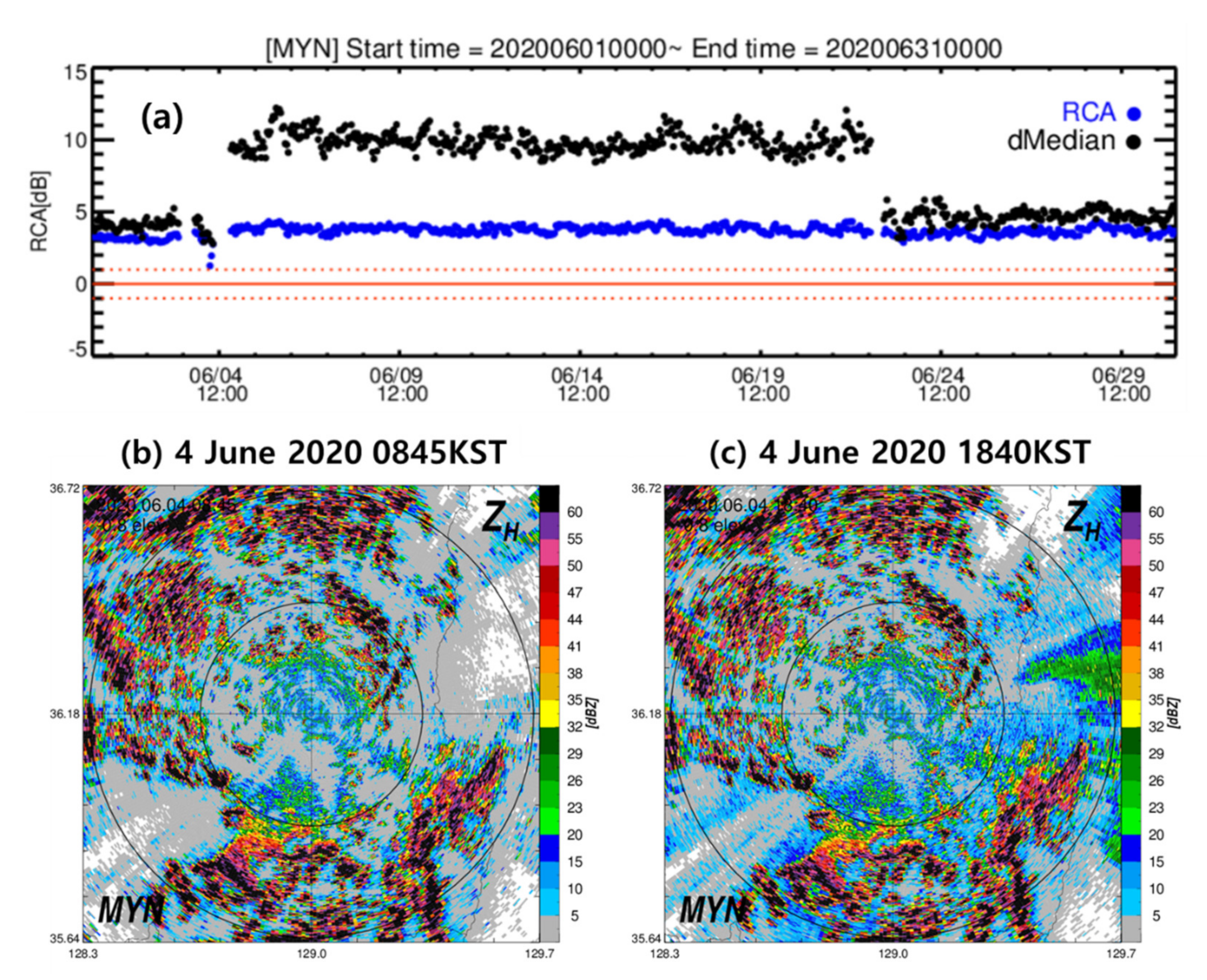
Figure 9a shows the RCA and dMedian for the MYN radar from 0000 KST 1 June 2020, to 0000 KST 31 June 2020. The MYN radar was shut down on 0845 KST on 4 June 2020, for routine inspection. The ZC,50th significantly changed when the radar restarted operation (at 1840 KST, 4 June 2020). Figure 9b and c show the PPIs observed at the MYN radar at an elevation angle of −0.8° on 0845 KST and 1840 KST on 4 June 2020. The location of the strong GC with a ZH of more than 50 dBZ rotated slightly in a counterclockwise direction. The dMedian was significantly changed during P2 because of the rotation of the azimuth angle, while the RCA slightly changed (approximately 1 dB).

4.1.3. Change in RCA due to the Calibration Status

The RCA of GDK, KSN, PSN, and SSP radars changed slightly after the routine inspection due to the change in calibration status, such as loss in the transmission path, radar constant, and transmitted power. The mean RCA of GDK radar for P1 was −0.11 dB with a STD of 0.17 dB, while the mean RCA of GDK radar for P2 was 0.69 dB with a STD of 0.15 dB. Moreover, the εSC changed from 0.04 dB to −1.11 dB. The εSC was close to 0.0 dB for P1 and −1.0 dB for P2. The difference in mean RCA between P1 and P2 (+0.80 dB) and the change in εSC (−1.15 dB) were similar. This resulted from the change in loss in the transmission path (1.67 to 1.29 dB) and transmitted power (671.82 to 667.38 kW). The RCA of KSN radar for each period was −0.02 ± 0.20 dB, −1.09 ± 0.18 dB, and −1.44 ± 0.20 dB. The mean RCA of PSN radar slightly changed two times (P1–P2: −0.17 to −0.31 dB, P2–P3: −0.31 to −0.57 dB). The mean RCA of the SSP radar slightly changed from 0.03 dB (P1) to −0.35 dB (P2). For the MYN radar, RCA significantly changed at the end time of P1. This change was due to the change in calibration bias (εSC decreased from 3.64 to 0.63 dB). The calibration bias (0.98 dB, red dot in Figure 7) was estimated from ΔRCA (2.66 dB, RCA at the end of P1 was 0.63 dB, RCA at the start of P2 was 3.29 dB) despite clear weather. It was noted that GC monitoring is valuable for use in an operational environment, especially during the non-precipitation period. The RCA of the GSN radar significantly changed twice due to the change in calibration bias. The ΔRCA was used to estimate the calibration bias in ZH using the GSN radar (red dots in Figure 7). The change in RCA (P1–P2: 0.12 to 3.97 dB, ΔRCA = 3.85 dB, P2–P3: 4.24 to 0.05 dB, ΔRCA = 4.19 dB) was similar with the change in εSC (P1–P2: −1.45 to −6.14 dB, P2–P3: −6.14 to −1.12 dB). When the RCA changed, the εGC could be estimated regardless of weather conditions, and it was similar to the εSC estimated on the next precipitation event.

4.2. Evaluation of Calibration Bias

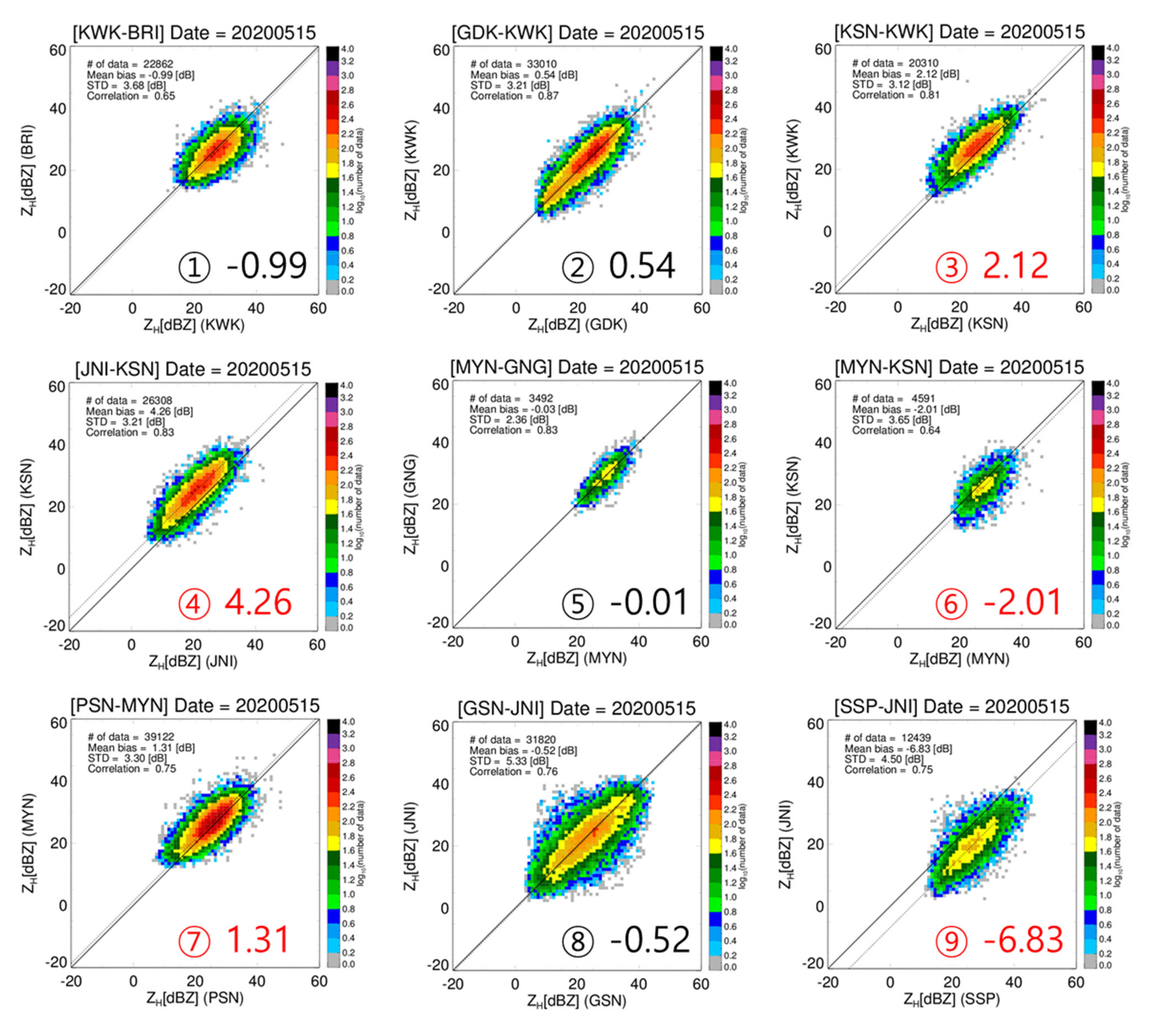
In this section, the daily mean bias was calculated between adjacent radars to evaluate εSC. Figure 10 shows the scatter plots of ZH in the overlapping volumes from the matched radar pairs before applying the calibration bias for a rain case on 15 May 2020. For each radar pair, the slope of the ZH was parallel to the 1:1 line, so the difference between the two radars was caused by the calibration bias. The comparison was valid because the number of pairs of ZH was at least 3,392. The GNG was well-calibrated during the entire period as shown in Figure 7. The calibration bias of MYN can be estimated using the mean bias for the MYN-GNG pair. The mean bias for the MYN-GNG pair was −0.01 dB. Therefore, we can expect that the calibration bias of MYN was close to 0.0 dB (The εSC of MYN was 0.63 dB on this event). The ZH of KSN was less than −2.01 dB compared to MYN and higher than 4.26 dB compared to JNI. That means the ZH of JNI was less than −6.26 dB compared to GNG. Furthermore, the ZH of JNI was similar to that of GSN (mean bias of GSN-JNI pair was −0.52 dB). The calibration bias of JNI and GSN was close to −6.0 dB. The εSC of JNI and GSN radar for 15 May 2020 in Figure 7 were −6.25 dB and −6.14 dB, respectively. To sum up, the mean bias before calibration bias allowed us to determine the mis-calibrated radar if there is a well-calibrated radar over the radar network.
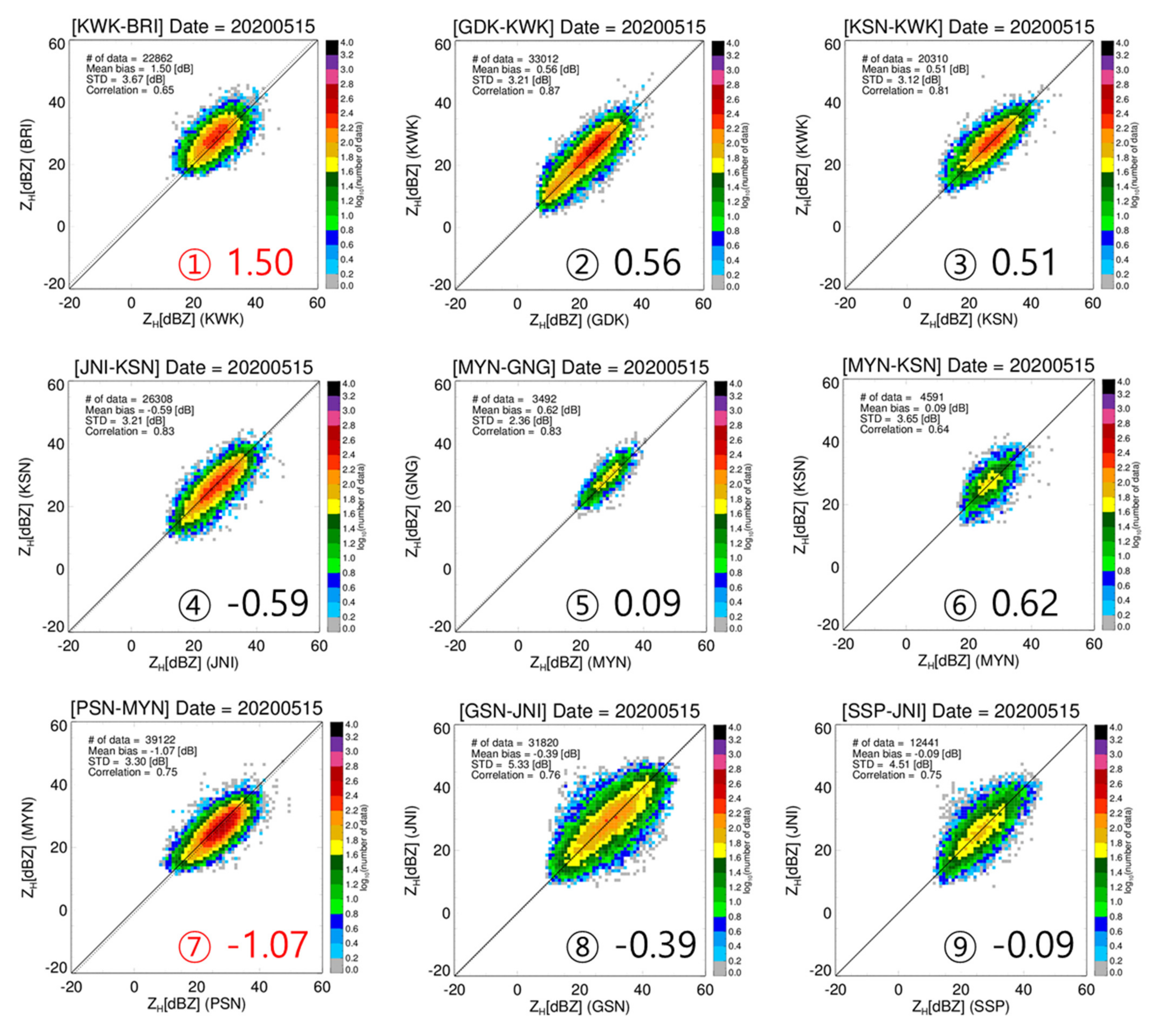
Figure 11 shows the mean bias for each radar pair in Figure 10 after applying εSC. If εSC was not calculated during precipitation events, the εSC calculated on the former or latter event was applied. The mean biases of JNI-KSN and SSP-JNI pairs were reduced to −0.59 and −0.09 dB, and these were further reduced to values closer to 0.0 dB after correcting the εSC. This result proved that εSC was well calculated. For all radar pairs, the mean bias ranged from −6.83 dB to 4.26 dB before applying εSC. On the other hand, the mean bias ranged from −1.07 to 1.75 dB after applying εSC.
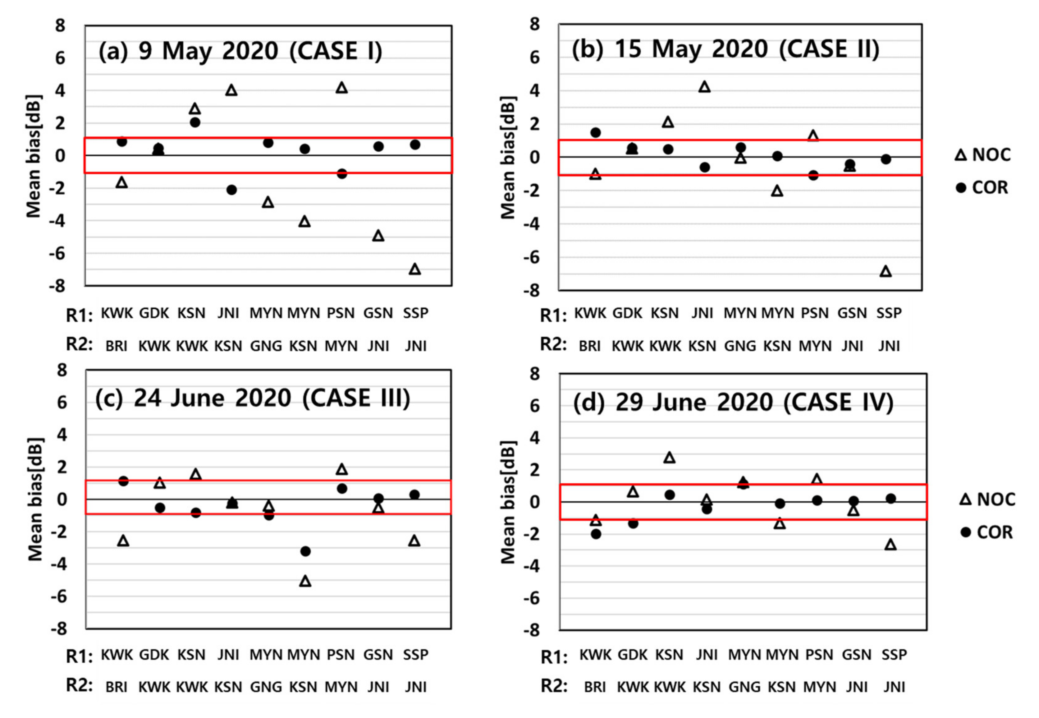
Figure 12 represents the mean bias before (triangles) and after (dots) applying εSC to four rainfall events. These four events were widespread precipitation events passing through the Korean Peninsula. The red line indicates the mean bias within ±1.0 dB. The mean bias before correcting εSC shows a large inhomogeneity of ZH over the radar network. For CASE I, the mean biases of all radar pairs except for the GDK-KWK pair were greater than ±1.0 dB. For the MYN-GNG, MYN-KSN, and PSN-MYN pairs, the mean biases were −2.85, −4.02, and 4.18 dB, respectively, due to the large calibration bias of MYN (3.64 dB). The mean biases were reduced from −1.08 dB to 0.83 dB after correcting εSC. For the JNI-KSN, GSN-JNI, and SSP-JNI pairs, the calibration of JNI (−6.73 dB) caused large mean biases (4.06 dB, −4.89 dB, and −6.94 dB). These mean biases were reduced to −2.09 dB, 0.6 dB, and 0.69 dB after correcting εSC. For CASE III and CASE IV, the mean bias between the two radars was noticeably reduced after correcting the εSC. The number of radar pairs with a mean bias greater than 1.0 dB decreased. As we mentioned, the GNG radar was a good reference because the εSC was close to 0.0 dB. The mean biases of MYN-GNG pair were −2.85 dB for CASE I and −0.03 dB for CASE II. The results indicate that the MYN radar was recalibrated between CASE I and CASE II. We determined the change in the calibration bias using the RCA in the previous section. We focused on the evaluation of εSC based on inter-comparison. However, the inter-comparison not only evaluated the consistency of data over the radar network, but also monitored the calibration bias during the rain period.

5. Summary and Conclusions

In this study, a technique for calculating and monitoring the calibration bias of S-band radar in a nationwide radar network was developed by combining GC monitoring, self-consistency (GC), and intercomparison. Each method has an advantage in that there is no need for large tasks for comparative analysis with other equipment. The combined method can calculate, monitor, and evaluate the calibration bias in real time regardless of weather conditions using radar data only.
The GC reflectivity (ZC) was statistically analyzed to estimate the calibration bias during the non-precipitation periods. The relative calibration adjustment (RCA) defined as the change in ZC relative to baseline, was calculated from the ground clutter map (GCM). The baseline for calculating RCA was determined from the ZC used to construct the GCM. We suggest two types of baselines (95th and 50th percentiles) to identify the change in antenna pointing (e.g., azimuth and elevation angle offset) and to calculate the RCA from the statistics of the ZC. The 50th percentile was used as an indicator (dMedian) to determine the azimuth and/or elevation slip change, while the 95th percentile was used to calculate the RCA. The calibration bias is estimated from the absolute calibration bias calculated based on SC of previous rain events and changes in RCA. The SC method between the differential phase and ZH was used to calculate the absolute calibration bias. Several criteria were considered to accurately estimate absolute calibration bias. The mean bias between two adjacent radars was calculated to verify the homogeneity of the radar network by applying the absolute calibration bias from SC method. For this purpose, the overlapping volume between two adjacent radars was determined based on radar beam geometry.
The RCA and absolute calibration bias in ZH for each site in the KMA network were analyzed. The RCA reflected changes in the radar status, such as changes in antenna pointing and calibration bias after routine inspection. The elevation and/or azimuth angle issues were revealed by significant change in dMedian and RCA. In addition, the change in RCA can be used to identify the change in calibration bias. Specifically, the calibration bias estimated from RCA is similar to that from SC. With the GC monitoring method, it is possible to estimate the calibration bias even when the calibration bias changes during the non-precipitation period. Moreover, the mean bias between adjacent radars was reduced to a value closer to 0.0 dB after calibration bias correction. This means that the homogeneity of ZH over a nationwide radar network can be improved through radar calibration. In other words, the calibration is a requirement for the quantitative use of ZH.
To summarize, we recommend how to make use of combined method according to weather condition and surrounding geography. SC and intercomparison require rain event, while GC monitoring method does not require rain event. If the GC exist near radar, it is possible to continuously know the calibration bias in time and monitor the radar status from the RCA with an interval of an hour during the non-precipitation period. During or after rain event, the absolute calibration bias of each radar and the mean bias between radars can be calculated. The absolute calibration bias and the mean bias let us know which radar has to be re-calibrated and how spatially uniform data can be used over the radar network.
We conclude that the combined method contributes to monitoring and estimating the calibration bias in ZH in real time. KMA currently monitors the ZH of operational weather radar based on combined method. As a result, high-quality data can improve operational algorithms, such as quantitative precipitation estimation and hydrometeor classification. In addition, monitoring of the calibration bias in real time is valuable so that radar engineers can carefully examine the radar system during and after routine inspection.

Author Contributions

This work was supported by significant contributions from all the authors. Conceptualization, S.-H.J., J.-E.L. and S.K.; methodology, S.-H.J., J.-E.L. and S.K.; software, J.-E.L., S.-H.J. and S.K.; formal analysis, J.-E.L.; investigation, J.-E.L.; writing—original draft preparation, S.-H.J. and J.-E.L.; writing—review and editing, S.-H.J. and J.-E.L.; visualization, J.-E.L.; supervision, S.-H.J.; funding acquisition, S.-H.J. All authors have read and agreed to the published version of the manuscript.

Funding

This research was funded by “Development of radar based severe weather monitoring technology (KMA2021-03121)” project of the Weather Radar Center, Korea Meteorological Administration.

Institutional Review Board Statement

Not applicable.

Informed Consent Statement

Not applicable.

Conflicts of Interest

The authors declare no conflict of interest.

References

  1. Whiton, R.C.; Smith, P.L.; Harbuck, A.C. Calibration of weather radar systems using the sun as a radio source. In Proceedings of the 17th Conference on Radar Meteorology, Seattle, WA, USA, 26–29 October 1976; pp. 60–65. [Google Scholar]
  2. Pratte, J.F.; Ferraro, D.G. Automated solar gain calibration. In Proceedings of the 24th Conference on Radar Meteorology, Tallahassee, FL, USA, 27–31 March 1989; American Meteorological Society: Boston, MA, USA; pp. 619–622. [Google Scholar]
  3. Atlas, D. Radar calibration: Some simple approaches. Bull. Amer. Meteor. Soc. 2002, 83, 1313–1316. [Google Scholar] [CrossRef] [Green Version]
  4. Sempere-Torres, D.; Sanchez-Diezma, R.; Berenguer, M.; Pascual, R.; Zawadzki, I. Improving radar rainfall measurement stability using mountain returns in real time. Preprints. In Proceedings of the 31st Conference on Radar Meteorology, Seattle, WA, USA, 6–12 August 2003; American Meteorological Society: Boston, MA, USA; pp. 220–221. [Google Scholar]
  5. Melnikov, V.M.; Zrnic, D.S.; Doviak, R.J.; Carter, J.K. Calibration and Performance analysis of NSSL’s Polarimetric WSR88D; NOAA/NSSL Rep., 77; National Severe Storms Laboratory: Norman, OK, USA, May 2003. [Google Scholar]
  6. Free, A.D.; Patel, N.K.; Ice, R.L.; Boydstun, O.E. WSR-88D ORDA antenna gain and beamwidth algorithms. In Proceedings of the 23rd Conference on Interactive Information Processing Systems, San Antonio, TX, USA, 14–18 January 2007; American Meteorological Society: Boston, MA, USA. [Google Scholar]
  7. Silberstein, D.S.; Wolff, D.B.; Marks, D.A.; Atlas, D.; Pippitt, J.L. Ground clutter as a monitor of radar stability at Kwajalein, RMI. J. Atmos. Ocean. Technol. 2008, 25, 2037–2045. [Google Scholar] [CrossRef]
  8. Gorgucci, E.; Scarchilli, G.; Chandrasekar, V. Calibration of radars using polarimetric techniques. IEEE Trans. Geosci. Remote Sens. 1992, 30, 853–858. [Google Scholar] [CrossRef] [Green Version]
  9. Gorgucci, E.; Scarchilli, G.; Chandrasekar, V. Specific differential phase estimation in the presence of nonuniform rainfall medium along the path. J. Atmos. Ocean. Technol. 1999, 16, 1690–1697. [Google Scholar] [CrossRef]
  10. Vivekanandan, J.; Yates, D.N.; Brandes, E.A. The influence of terrain on rainfall estimates from radar reflectivity and specific propagation phase observations. J. Atmos. Ocean. Technol. 1999, 16, 837–845. [Google Scholar] [CrossRef]
  11. Ryzhkov, A.V.; Giangrande, S.E.; Melnikov, V.M.; Schuur, T.J. Calibration issues of dual-polarization radar measurements. J. Atmos. Ocean. Technol. 2005, 22, 1138–1155. [Google Scholar] [CrossRef] [Green Version]
  12. Lee, G.W.; Zawadzki, I. Radar calibration by gage, disdrometer, and polarimetry: Theoretical limit caused by the variability of drop size distribution and application to fast scanning operational radar data. J. Hydrol. 2006, 328, 83–97. [Google Scholar] [CrossRef]
  13. Kwon, S.; Lee, G.W.; Kim, G. Rainfall estimation from an operational S-band dual-polarization radar: Effect of radar calibration. J. Meteor. Soc. Jpn. 2015, 93, 65–79. [Google Scholar] [CrossRef] [Green Version]
  14. Joss, J.; Waldvogel, A. A raindrop spectrograph with automatic analysis. Pure Appl. Geophys. 1967, 68, 240–246. [Google Scholar] [CrossRef]
  15. Brandes, E.A.; Vivekanandan, J.; Wilson, J.W. A comparison of radar reflectivity estimates of rainfall from collocated radars. J. Atmos. Ocean. Technol. 1999, 16, 1264–1272. [Google Scholar] [CrossRef]
  16. Ulbrich, C.W.; Lee, L.G. Rainfall measurement error by WSR88D radars due to variations in Z-R law parameters and the radar constant. J. Atmos. Ocean. Technol. 1999, 16, 1017–1024. [Google Scholar] [CrossRef]
  17. Anagnostou, E.N.; Morales, C.A.; Dinku, T. The use of TRMM precipitation radar observation in determining ground radar calibration biases. J. Atmos. Ocean. Technol. 2001, 18, 616–628. [Google Scholar] [CrossRef] [Green Version]
  18. Bringi, V.; Thurai, M.; Petersen, W.A.; Gatlin, P.N. Using a network of 2D video disdrometers for external radar calibration of NASA’s S-band polarimetric radar. In Proceedings of the 36th Conference on Radar Meteorology, Breckenridge, CO, USA, 16–20 September 2013. [Google Scholar]
  19. Park, S.; Jung, S.-H.; Lee, G. Cross validation of TRMM PR reflectivity profiles using 3D reflectivity composite from the ground-based radar network over the Korean Peninsula. J. Hydrometeorol. 2015, 16, 668–687. [Google Scholar] [CrossRef]
  20. Warren, R.A.; Protat, A.; Siems, S.T.; Ramsay, H.A.; Louf, V.; Manton, M.J.; Kane, T.A. Calibrating ground-based radars against TRMM and GPM. J. Atmos. Ocean. Technol. 2018, 35, 323–346. [Google Scholar] [CrossRef]
  21. Keem, M.; Seo, B.-C.; Krajewski, W.F.; Morris, K.R. Inter-comparison of reflectivity measurements between GPM DPR and NEXRAD radars. Atmos. Res. 2019, 226, 49–65. [Google Scholar] [CrossRef]
  22. Rinehart, R.E. On the use of ground return targets for radar reflectivity factor calibration checks. J. Appl. Meteorol. Climatol. 1978, 17, 1342–1350. [Google Scholar] [CrossRef] [Green Version]
  23. Wolff, D.B.; Marks, D.A.; Petersen, W.A. General application of the relative calibration adjustment (RCA) technique for monitoring and correcting radar reflectivity calibration. J. Atmos. Ocean. Technol. 2015, 32, 496–506. [Google Scholar] [CrossRef]
  24. Hunzinger, A.; Hardin, J.; Bharadwaj, N.; Varble, A.; Matthews, A. An extended radar relative calibration adjustment (eRCA) technique for higher-frequency radars and range-height indicator (RHI) scans. Atmos. Meas. Tech. 2020, 13, 3147–3166. [Google Scholar] [CrossRef]
  25. Vaccarono, M.; Bechini, R.; Chandrasekar, C.V.; Cremonini, R.; Cassardo, C. An integrated approach to monitoring the calibration stability of operational dual-polarization radars. Atmos. Meas. Tech. 2016, 9, 5367–5383. [Google Scholar] [CrossRef] [Green Version]
  26. Louf, V.; Protat, A.; Warren, R.A.; Collis, S.M.; Wolff, D.B.; Raunyiar, S.; Jakob, C.; Petersen, W.A. An integrated approach to weather radar calibration and monitoring using ground clutter and satellite comparisons. J. Atmos. Ocean. Technol. 2019, 36, 17–39. [Google Scholar] [CrossRef] [Green Version]
  27. Crisologo, I.; Heistermann, M. Using ground radar overlaps to verift tge retrieval of calibration bias estimates from spaceborn platforms. Atmos. Meas. Tech. 2020, 13, 645–659. [Google Scholar] [CrossRef]
  28. Lee, J.-E.; Jung, S.-H.; Kim, J.-S.; Jang, K. Sensitivity analysis of polarimetric observations by two different pulse lengths of dual-polarization weather radar. Atmosphere 2019, 29, 192–211, (In Korean with English abstract). [Google Scholar]
  29. Oh, Y.-A.; Kim, H.-L.; Suk, M.-K. Clutter elimination algorithm for non-precipitation echo of radar data considering meteorological and observational properties in polarimetric measurements. Remote Sens. 2020, 12, 3790. [Google Scholar] [CrossRef]
  30. Lee, S.-H. Detection of Bright Band and Analysis of Its Characteristics Using the KMA Weather Radar Data. Master’s Thesis, Kyung National University, Daegu, Korea, June 2012. [Google Scholar]
  31. Delrieu, G.; Creutin, J.D. Simulation of radar mountain returns using a digitized terrain model. J. Atmos. Ocean. Technol. 1995, 12, 1038–1049. [Google Scholar] [CrossRef] [Green Version]
  32. Kucera, P.A.; Krajewski, W.F.; Young, C.B. Radar beam occultation studies using GIS and DEM technology: An example study of Guam. J. Atmos. Ocean. Technol. 2004, 21, 995–1006. [Google Scholar] [CrossRef] [Green Version]
  33. Park, S.-G.; Lee, G. Calibration of radar reflectivity measurements from the KMA operational radar network. Asia-Pac. J. Atmos. Sci. 2010, 46, 243–259. [Google Scholar] [CrossRef]
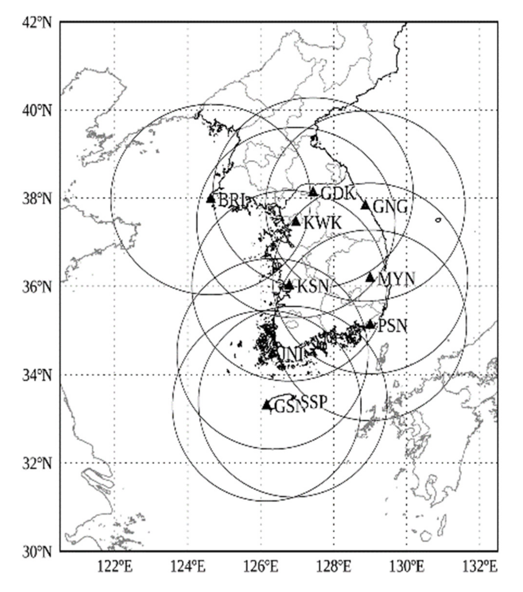
Figure 1. Deployment of KMA’s S-band dual-polarization weather radar network. The ten circles indicate the 240 km radius coverage of each radar within the KMA network.
Remotesensing 13 02936 g001
Figure 2. Concepts of calculating and monitoring of calibration bias in the ZH measurements in real time.
Remotesensing 13 02936 g002
Figure 3. Example of ground clutter map (GCM) for GSN radar constructed at 0000 KST 1 May 2020.
Remotesensing 13 02936 g003
Figure 4. Scatter plot of the calculated and measured differential phase from GSN radar for the rainfall event on 3 July 2020. The red solid line represents the calibration bias (εSC), while the red dashed lines represent the εSC ± 1 dB.
Remotesensing 13 02936 g004
Figure 5. Example of selection of overlapping volume of the two radars. (a) Overlapping volume at equidistance between adjacent radars. The black dashed line indicates the range of azimuth angles including equidistance line. (b) Example for the selection of overlapping volumes between adjacent radars (GSN and JNI radar). The solid vertical line indicates the range at the center of equidistance. The solid (dotted) lines indicate the height at center (top and bottom) of the radar beams. The top and bottom of the radar beams are defined by considering the beam width. The red lines represent the matched elevation angles relative to blue line.
Remotesensing 13 02936 g005
Figure 6. Time series of radar calibration adjustment (RCA) at each radar within the KMA network from 1 May 2020 to 31 July 2020. The P1, P2, and P3 is the period with the similar RCA.
Remotesensing 13 02936 g006
Figure 7. Time series of radar absolute calibration bias estimated from SC (blue dot) and change in the RCA (red dot) at each radar site from 1 May 2020 to 31 July 2020. The vertical dotted lines represent the period with similar RCA (P1, P2 and P3) shown in Figure 6.
Remotesensing 13 02936 g007
Figure 8. Example of elevation angle slip issue. (a) Time series of RCA (blue) and dMedian (black) for MYN radar from 0000 KST 1 June 2020 to 0000 KST 31 June 2020. The black and blue dots represent the RCA and dMedian. PPIs of ZH at the elevation angle of −0.2° of KWK radar at (b) 1 June 2020 1100 KST (P1), (c) 1 June 2020 1100 KST (P2), and (d) 25 June 2020 1100 KST (P3).
Remotesensing 13 02936 g008
Figure 9. Example of azimuth angle slip issue. (a) Time series of ground clutter (GC) reflectivity statistics for MYN radar from 0000 KST 1 June 2020 to 0000 6 June 2020. The black and blue dots represent the RCA and dMedian. (b,c) PPIs of ZH at the elevation angle of −0.8° of MYN radar at 6 June 2020 0845 KST and 1840 KST. The rings are intervals of 30 km.
Remotesensing 13 02936 g009
Figure 10. Scatter plots of radar reflectivity between two radars during the 15 May 2020 before calibration bias correction. The dashed line represents the mean bias of the reflectivity. The numbers from (1) to (9) correspond to the order of matched radar pairs in Table 2. The black numbers indicate the mean bias within ±1 dB, while the red numbers indicate the mean bias out of ±1 dB.
Remotesensing 13 02936 g010
Figure 11. Same as Figure 10 after calibration bias correction.
Remotesensing 13 02936 g011
Figure 12. Mean bias of reflectivity between two radars for 4 rainfall events: (a) 9 May 2020, (b) 15 May 2020, (c) 24 June 2020 and (d) 29 June 2020. The R1 represents the reference radar, while the R2 represents the matched radar. The triangle and dot indicate the mean bias before (triangle) and after (dot) calibration bias correction, respectively.
Remotesensing 13 02936 g012
Table 1. Scan strategy of each radar within the KMA network.
RadarElevation Angle (°)
High PRF [Hz]
GDK−0.400.010.310.801.412.504.207.1115.01
62062062062062062083012001200
BRI0.100.420.811.412.203.415.107.6115.01
62062062062062068093512001200
KWK−0.190.000.300.811.502.604.407.3015.01
62062062062062062083012001200
MYN−0.80−0.390.010.410.911.913.607.0015.01
52553056059562068068012001200
KSN0.000.300.701.302.103.215.007.6115.01
62062062062062065093512001200
PSN−0.090.200.601.101.813.004.717.4015.01
62062062062062062088012001200
JNI−0.090.200.601.101.813.004.717.4215.02
62062062062062065088012001200
SSP0.200.501.011.602.413.505.207.6015.00
62062062062062068093512001200
GSN0.200.501.011.602.413.505.207.6015.01
62062062062062068093512001200
Table 2. Scan strategy of GSN radar, which is one of KMA operational S-band dual-polarization radars.
SiteElev. No.Elevation (°)Range (km)Pulse Width (μs)High PRF (Hz)Dual PRFNyquist Velocity (m s−1)Antenna Scan Speed (ºs−1)Sampling Number
GSN10.22402.06205:465.812.045
20.52402.06205:465.812.045
31.02402.06205:465.812.045
41.62402.06205:465.812.045
52.42402.06205:465.812.045
63.52201.06805:472.213.045
75.21601.09355:499.218.045
87.61201.012005:4127.424.045
915.0601.012005:4127.424.045
Table 3. Distance and the number of overlapping volumes for the matched radar pair.
Radar 1
(Reference)
Radar 2Distance between
Two Radars (km)
Number of Overlapping
Volumes
KWKBRI214575
GDKKWK861240
KSNKWK1601064
JNIKSN176762
MYNGNG183500
MYNKSN200595
PSNMYN1181595
GSNJNI132846
SSPJNI131987
Table 4. Mean and standard deviation (STD) of RCA at each site. The periods are divided by the change in RCA.
SiteP1P2P3
MeanSTDMeanSTDMeanSTD
GDK−0.110.170.690.16--
KWK−0.110.1522.622.79−0.590.16
GNG−0.140.16----
MYN0.130.263.100.293.590.29
KSN−0.020.2−1.090.18−1.440.20
PSN−0.170.1−0.310.12−0.600.13
SSP0.030.14−0.350.23−0.040.15
GSN0.060.094.160.100.120.14
Publisher’s Note: MDPI stays neutral with regard to jurisdictional claims in published maps and institutional affiliations.