1. Introduction
Accuracy, integrity, continuity, and availability are the four core performance indicators of satellite navigation systems. Among them, integrity refers to the ability of the system to alert users in time when the service is abnormal or experiences failure, and it characterizes the security and reliability of system services [
1,
2]. If there is an abnormality or failure in the service, but the system fails to detect it or fails to alarm in time, an “integrity event” has occurred. Once an integrity event occurs, it will have a security impact on the user, especially for civil aviation, maritime, railway, and other users related to life safety. System reliability is even more strategically important with the widespread use of low-cost sensors for various applications including personal positioning and autonomous navigation [
3,
4]. In addition, the integrity of the core constellation is also an important foundation for the construction of the satellite-based augmentation systems (SBAS) such as WASS (wide area augmentation system) [
5,
6], ENGOS (European geostationary navigation overlay system) [
7,
8], MSAS (multi-functional satellite augmentation system) [
9,
10], BDSBAS (BeiDou satellite-based augmentation system) [
11], and airport ground-based augmentation systems (GBAS). These augmentation systems are constructed to further augment the global navigation satellite system (GNSS) constellation and provide higher integrity navigation services.
Satellite navigation systems in the world are paying more and more attention to the construction and improvement of their integrity capabilities. GPS and Galileo considered their integrity function at the beginning of the system design, defined the integrity parameters and algorithms, and planned its application scenarios [
2,
12,
13,
14]. China’s BeiDou also attaches importance to the construction of integrity. China’s BeiDou global navigation satellite system (BDS-3) carried out a brand new integrity concept design work, which defines and achieves the integrity functions for major civil open service (OS) signals such as B1C, B2a, and B1I. In addition to GNSSs, regional satellite navigation systems have also begun to upgrade their integrity capabilities. For example, Japan’s QZSS not only defines and provides the integrity function for its basic positioning, navigation, and timing (PNT) service, but also for its sub-meter level augmentation service (SLAS) and centimeter-level augmentation service (CLAS) [
15,
16].
Due to the numerous components, functions, and processing operations of the system, it is not easy to ensure the integrity of satellite navigation systems, especially for global ones. On 13 July 2019, a mass outage occurred in Galileo—all 24 networking satellites in orbit entered an “unavailable” or “test” state, and the system was immediately paralyzed. After 48 h of full maintenance, the system did not return to normal until 8 o’clock on 18 July. During this period, the service was knocked offline for up to 117 h (about 5 days) [
17]. Although the European GNSS Agency (GSA) issued a warning of service outage on the Galileo official website at 20:00 on 13 July [
18], it still had a serious impact on users around the world. This incident also prompted countries to take measures to ensure the safe operations of satellite navigation systems. After this incident, Russia stated that it has set up a multi-level software detection system in the ground segment of GLONASS, with a redundant design and an autonomous control function to prevent such failures from occurring.
On 27 December 2018, BDS-3 completed the construction of the basic constellation (consisting of 18 MEOs) and began to provide the initial global service [
19]. On 31 July 2020, BDS-3 completed all construction (consisting of 24 MEOs, 3 IGSOs, and 3 GEOs) tasks and officially opened the global service [
20]. Since the initial service was provided, BDS-3 has been in a stable operation state, and there have been no integrity events affecting the system and user services. This benefits from the reasonable system design and effective risk monitoring and control measures. However, this does not mean that BDS-3 has completely eliminated the integrity hazards, especially considering that the system was built in such a short period of time (2012–2020). To ensure the safety and reliability of the service, it is necessary and valuable to carry out more in-depth research and evaluation.
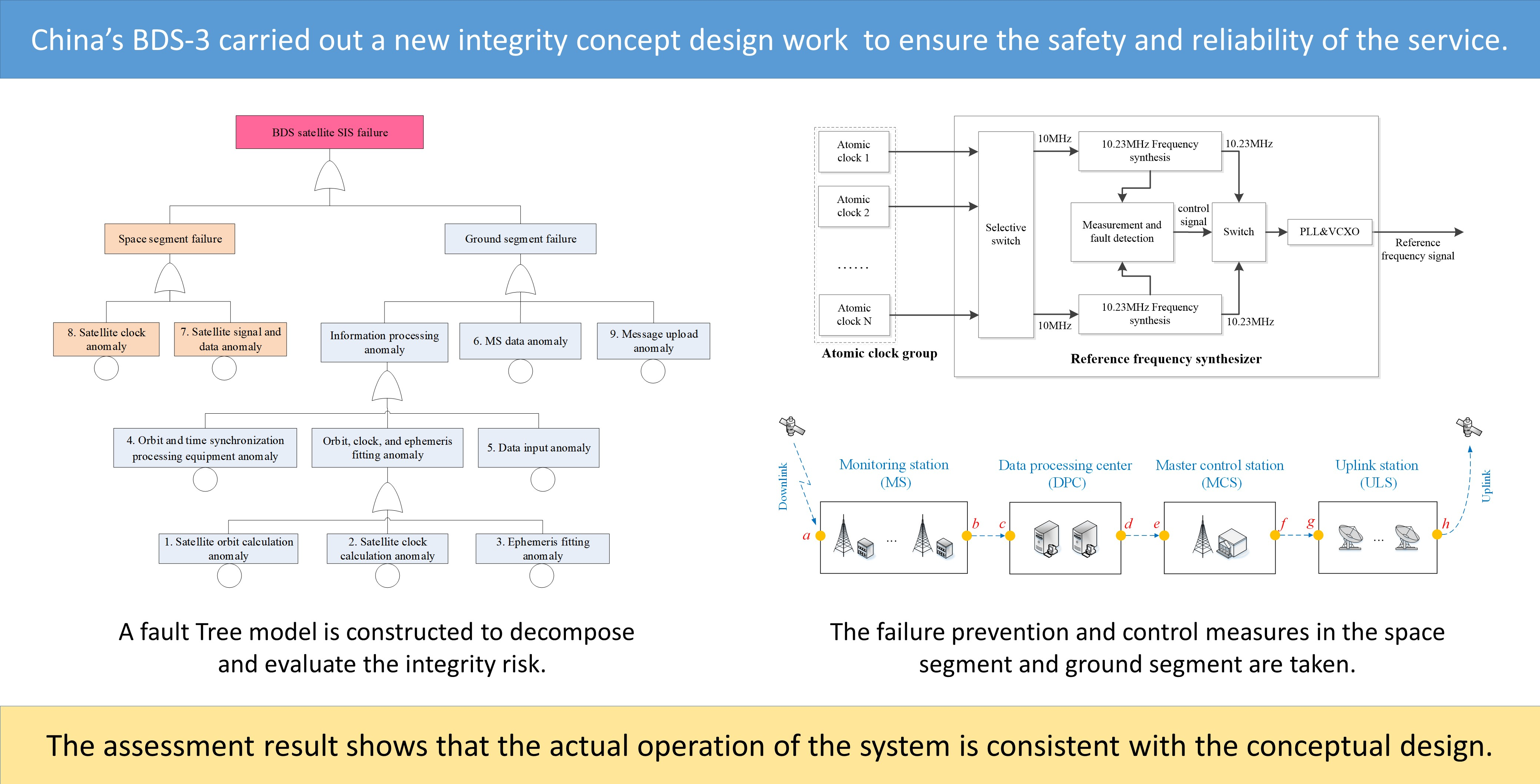
This study focuses on the design and the performance analysis of BDS-3’s integrity concept. In order to improve the reliability and safety of the service, BDS-3 upgraded and improved the conceptual design and function of integrity compared to BDS-2 and carried out standard development work in ICAO SARPs at the same time. The satellite service failure and constellation service failure concepts are clearly defined, and the integrity risk probability calculation method is designed for the three OS signals of B1I/B1C/B2a. The integrity fault tree model is studied and established, and the corresponding monitoring measures for weakness in the space segment and the ground segment of the system is proposed. In terms of alarms, BDS-3 is designed with a hybrid alarm mechanism of the ground alarm approach and the satellite alarm approach, to make up for the limitations for BDS’s failure to deploy ground monitoring stations globally. Finally, the actual operation data of 2019 was used to verify the integrity performance of the system service. The results show that the actual operation of the system is consistent with the conceptual design, which proves the safety and reliability of the BDS-3 OS service.
The remainder of this paper is structured as follows.
Section 2 defines the integrity of the BDS OS signals (B1I/B1C/B2a), introduces the alarm approach, and gives the calculation method of the satellite service failure probability (P
sat) and the constellation service failure probability (P
const). In
Section 3, a fault tree model for the BDS satellite signal-in-space (SIS) is established, the bottom events from the space segment and the ground segment are decomposed, and the system design values of P
sat and P
const are derived. In
Section 4, the integrity prevention and control measures taken by BDS-3 in the space segment and the ground segment are introduced, respectively. Finally,
Section 5 presents the integrity risk verification work on BDS-3 and the analyses of the results.
2. BDS Integrity Concept
This section first introduces the integrity definition of BDS-3 under the ICAO framework, which includes two concepts: Psat and Pconst. Secondly, the hybrid alarm mechanism of BDS-3, which has both the ground alarm approach and the satellite alarm approach, is explained. This hybrid design is mainly to make up for the limitations for BDS’s failure to deploy ground monitoring stations globally.
2.1. Integrity Definition
Due to the high requirements for safety and reliability, the concept of navigation integrity first appeared in the field of civil aviation. In order to be approved for the application in the field of civil aviation, GNSSs need to carry out and complete their standard research and formulation work under the ICAO framework, and promise ICAO all necessary service performance indicators, including integrity.
According to the definition in the ICAO international standards and recommended practices (SARPs), integrity indicates the system’s ability to detect faults and issue alerts. In order to make more detailed and accurate assessments, the integrity probability is further subdivided into the “satellite service failure probability” (denoted as Psat) and the “constellation service failure probability” (denoted as Pconst). Among them, the “satellite service failure” refers to the condition where the user range error (URE) of any single satellite exceeds the broadcast not-to-exceed (NTE) tolerance but the alarm cannot be achieved within the promised time. This type of failure will only affect itself and no other satellites. The “constellation service failure” refers to the condition where the UREs of more than two satellites exceed the corresponding NTEs at the same time, and the alarm cannot be achieved within the promised time. Once this type of failure appears, it means that some kind of common fault has occurred in the system.
ICAO allows the GNSS to develop its customized integrity technical content. See
Table 1 for the integrity risk probability indicator of each GNSS in ICAO SARPs [
19,
21].
It can be seen from
Table 1 that the integrity functions of each GNSS are quite different. GPS has global ground monitoring and injection capabilities, so once the service is abnormal, the system can send an alert in real time. Specifically, there are several alarm approaches for GPS, including using the health status indicator in the message, setting the satellite pseudo random number (PRN) code to “37”, or broadcasting non-standard PRN codes. GLONASS indicates the operating status of the system to users through the health status indicator in the message. Galileo provides users with integrity information through the HS, DVS, SISA, and other parameters in the message; in addition, when the issue of data (IOD) of the message exceeds four hours, it also indicates that the system message is in an unhealthy state. BDS-3 is designed with two methods of ground integrity monitoring and satellite autonomous integrity monitoring (SAIM). Among them, the ground integrity monitoring approach provides users with integrity information through HS, SIF, DIF, SISA, and other parameters in the message; SAIM can provide users with integrity information through message parameters or non-standard PRN codes. In addition, the NTE tolerances of GPS, Galileo, and BDS are broadcasted to users as message parameters, while the NTE tolerance of GNLOASS is fixed to 70 m.
2.2. Alarming Approach
This section introduces the alarming mechanism of BDS-3. BDS-3 is designed with a hybrid alarming mechanism of the ground monitoring and alarm approach and the satellite monitoring and alarm approach, to make up for the limitations for BDS’s failure to deploy ground monitoring stations globally.
2.2.1. Ground Monitoring and Alarming
The ground monitoring and alarm approach using the BDS ground segment facilities the monitoring of the signal quality and the URE of the satellite SIS. When the failure is detected, the user will be notified of the satellite SIS health status through the integrity parameters in the broadcast message. The designed TTA of the ground monitoring and alarming approach is better than 60 s, and the delay mainly comes from processes such as data transmission, information processing, and message update, etc. The new B1C and B2a signals and the original B1I signal of BDS have different integrity parameter designs and alarm mechanisms.
The B1I signal uses the “autonomous satellite health flag (SatH1)” parameter broadcast in the BDS D1 navigation message to indicate the satellite SIS health status, where “SatH1 = 0” indicates that the satellite SIS is available, and “SatH1 = 1” indicates that satellite SIS is not available (that is, URE > 4.17 × URA), which are shown in
Table 2 [
22,
23].
As a comparison, B1C and B2a signals use the “satellite health status (HS)” parameter to indicate the health status of the entire satellite, and the “signal integrity flag (SIF)” parameter to indicate the satellite SIS status. In addition, B1C and B2a signals use a “data integrity flag (DIF)” parameter to indicate the SIS accuracy (SISA) of satellites. This is mainly to take into account the differences in the sensitivity and tolerance of aviation and non-aviation users to satellite ranging errors. The integrity parameters of B1C and B2a signals are broadcast in sub-frame 3 of BDS B-CNAV1 and B-CNAV2 navigation messages, respectively [
24,
25]. As the update frequency of B-CNAV2 is higher, it is recommended to use the integrity parameters broadcast in B-CNAV2, for B1C/B2a dual-frequency users.
According to the above-mentioned integrity parameter design, B1C and B2a signals can take three different states as shown in
Table 3, with the following meanings:
“Healthy”: The SIS of the satellite meets the minimum service performance specified in the “BeiDou Open Service Performance Specification” [
22];
“Unhealthy”: The SIS of the satellite is not providing services or is under test;
“Marginal”: The signal is neither of the two previous states. For some types of users, it is acceptable and tolerable, but for others, it is not.
Further, the steps for the use of B1C and B2a signals can be described as following:
Step 1: Confirm whether the entire satellite is healthy according to the HS parameter in the message. If HS = 1, it indicates that the satellite is currently unhealthy, and the user should stop using the satellite. If HS = 0, it indicates that the satellite is currently healthy, and proceed to step 2.
Step 2: Confirm whether the satellite SIS is abnormal according to the SIF parameter in the message. If SIF = 1, it indicates that the satellite SIS has an anomaly affecting the pseudo-range, please stop using the satellite. If SIF = 0, it indicates that the satellite signal is normal, and proceed to step 3.
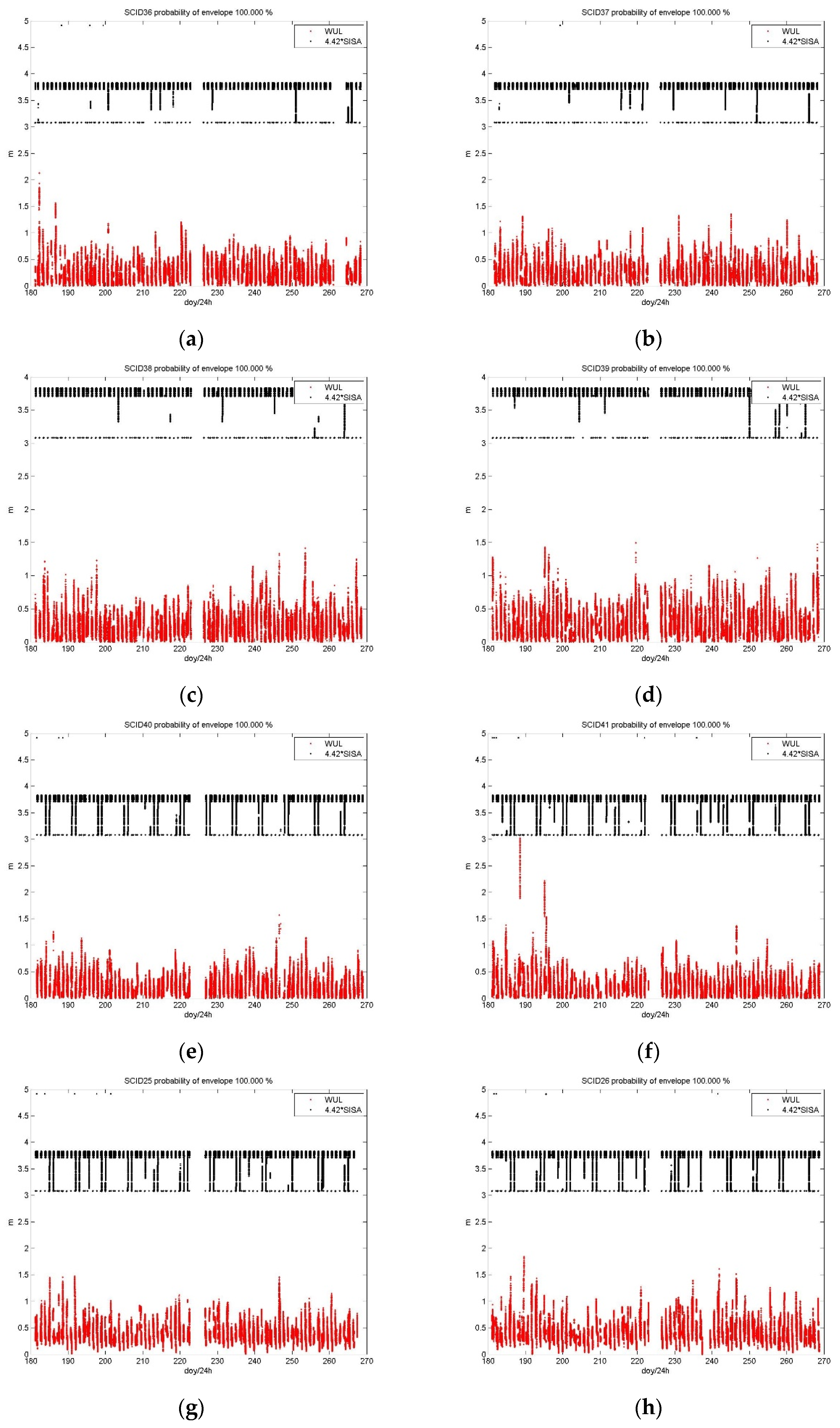
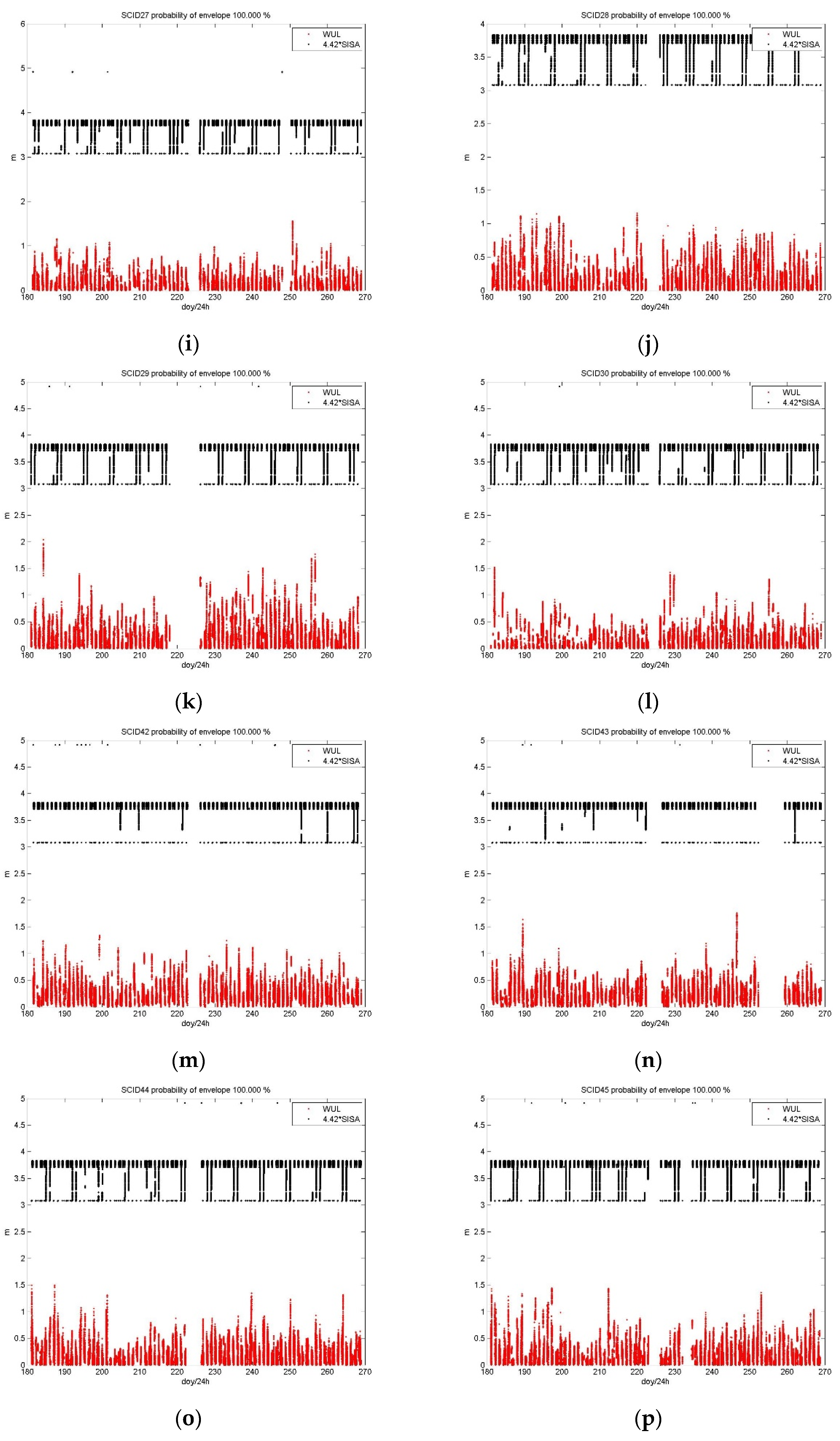
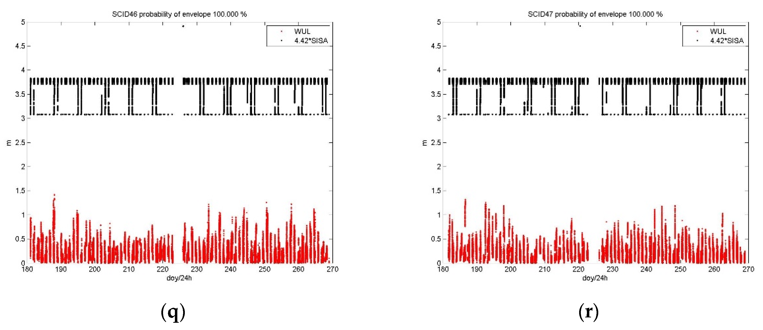
Step 3: Access the DIF parameter in the message. If DIF = 1, it indicates that the SISA of the satellite exceed the NTE (that is, URE > 4.42 × SISA), and it is not recommended for users in the life safety field, such as aviation users. However, for the satellite, this is just that its SISA exceeds the limit at this time, not a failure. Other users who have less strict safety requirements can still choose to use it (for example, users in the mass consumer sector). If DIF = 0, it indicates that the SISA of the satellite does not exceed the NTE, and all users can use it with confidence.
Currently, this alarm approach has been implemented in B1C and B2a signals. Here, we want to further highlight the design significance of DIF. The introduction of DIF is mainly to take into account the differences in the sensitivity and tolerance of aviation and non-aviation users to satellite ranging errors. We hope that while ensuring integrity, the use of DIF will help improve the continuity and availability for non-aviation users.
2.2.2. Satellite Monitoring and Alarming
The satellite monitoring and alarming approach includes two mechanisms. One is that the satellite sends back the SIS quality monitoring information to the ground, and after the ground segment confirms the fault, the alert notification is sent to the satellite through the inter-satellite link (ISL). According to the topology of BDS ISL and the en-route operation performance requirements of ICAO, the TTA is designed to be 300 s.
Another mechanism is that the satellite uses the on-board SAIM equipment to monitor the satellite clock, SIS quality, and SIS-URE in real time without the need for ground confirmation. This mechanism can achieve a very fast alarm speed, and the expected TTA for it is 6 s. At present, this alarm approach is in the on-board testing stage, and BDS is working hard to implement this rapid alarm mechanism as soon as possible and has not ruled out the use of non-standard PRN codes and other alert notifications.
The use of the satellite monitoring and alarm approach is mainly to make up for the limitations for BDS’s failure to deploy monitoring stations globally. When BDS satellites are located in China, the system will use the ground monitoring and alarm approach; when BDS satellites are located outside of China, it will mainly rely on the satellite monitoring and alarm approach to ensure the integrity of satellites.
2.3. Psat and Pconst Calculations
2.3.1. Psat Calculation for B1I
For any satellite at any time
t, the B1I SIS health status is determined as following:
where SatH1 is the integrity status parameter of B1I.
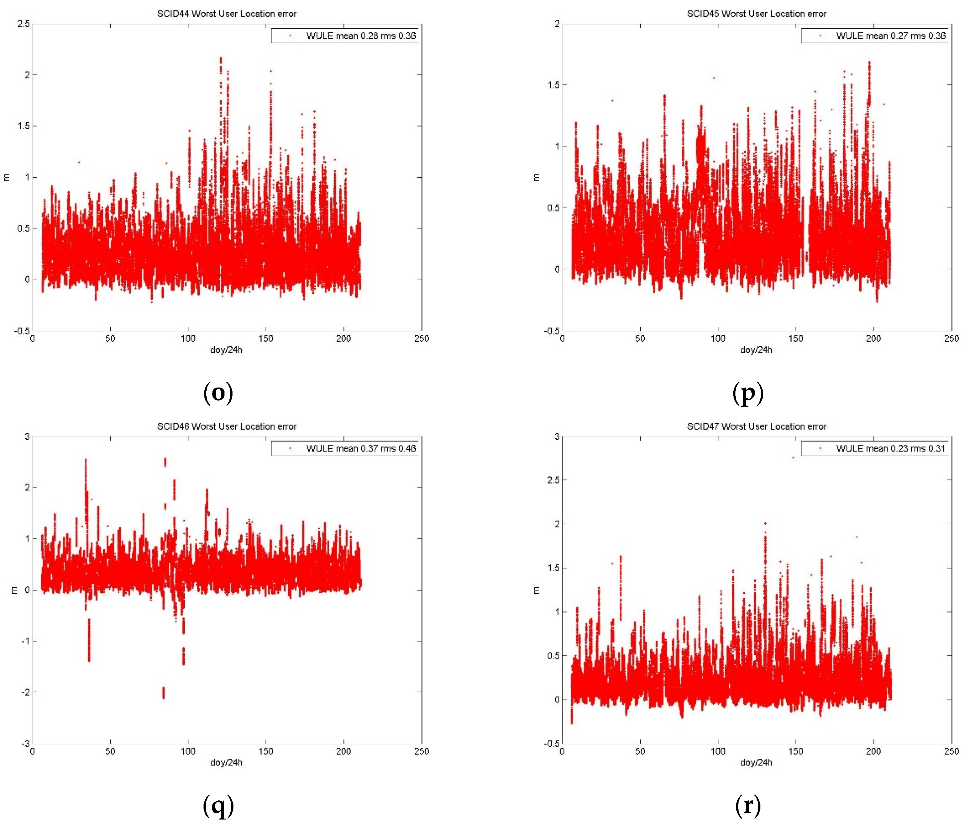
Using the precision satellite orbit product to calculate the along-track error (denoted as
), cross-track error (denoted as
), and radial error (denoted as
) of the satellite orbit in the broadcast NAV message, and using the precision satellite clock product to calculate the satellite clock error (denoted as
) in the broadcast NAV message. Their projection to the worst user location (WUL) position can be obtained by Equation (2) [
26,
27].
where
is the projection factor at the WUL results from the approximation of the ratio
, with
is the mean earth’s radius and
is the semi major axis of the BDS satellites orbit.
is given in
Table 4 for MEOs and GEO/IGSOs, respectively.
The satellite service failure condition of the B1I signal is determined by the following logical function over the hour interval:
where the URA indicator of the B1I signal can be obtained via the user range accuracy index (URAI) broadcast in the D1 NAV message of B1I [
23].
Faults have a finite duration before they are either corrected or before the user is notified. Here, we use the term mean time to notify (MTTN) in hours to denote the expected average fault duration [
27,
28]. On this basis, P
sat of a year is defined as the ratio of the MTTN duration of satellite failure conditions to the total hours of all satellites in the constellation, which can be expressed as follows:
where
is the total number of failure satellites of a year,
is the total hours of a year, and
is the nominal number of satellites in the constellation (for BDS is 27 in ICAO SAPRs).
2.3.2. Psat Calculation for B1C and B2a
For any satellite at any time
t, the B1C/B2a SIS health status is determined by the integrity parameters as follows:
where HS, SIF, and DIF are the integrity status parameters of B1C/B2a.
The SISURE of the B1C/B2a signal is calculated using the same method as the B1I signal in
Section 2.3.1, and the satellite service failure condition is determined as follows:
where the SISA indicators of B1C and B2a signals can be obtained by the SIS accuracy index (SISAI) broadcast in the B-CNAV1 [
24] and B-CNAV2 [
25] navigation messages, respectively.
More specifically, SISA can be calculated by the function as following [
24,
25,
29]:
where SISA
oe denotes the elevation-dependent component, and SISA
oc denotes the non-elevation-dependent component. After that, Equation (4) is also suitable for calculating the P
sat of B1C and B2a signals.
2.3.3. Pconst Calculation
P
const is obtained through statistics, which can be expressed as following:
where
represents the total time in a year that two or more satellites fail due to a common cause at the same time.
3. Integrity Risk Probability Distribution
In this section, a fault tree model for the BDS satellite SIS is constructed, and the main integrity risk bottom events from the space segment and the ground segment are sorted out and decomposed. By analyzing them one by one, the design values of Psat and Pconst of the system are deduced and determined. At present, these technical indicators have been written into the latest draft of ICAO SARPs.
3.1. Integrity Risk Tree Model
The risk tree method is a graphical model of expressing the logical relationship between a particular failure condition and the causes or failures leading to this condition. It is an application of fault tree analysis being used in the aerospace industry [
21].
The BDS satellite SIS integrity failure comes from the space segment and the ground segment. The bottom events of the space segment failure include the satellite clock anomaly, and the satellite signal and data anomaly (specifically, the transmitting power anomaly, the message data anomaly, the code-carrier inconsistency, and the signal distortion).
The bottom events of the ground segment failure include the satellite orbit processing anomaly, the satellite clock processing anomaly, the ephemeris fitting anomaly, the data input anomaly, the orbit and time synchronization processing equipment anomaly, the monitoring station (MS) data anomaly (including the transmission link failure between the MS and the master control station (MCS)), and the message upload anomaly (including the upload failure caused by control instruction faults and configuration faults).
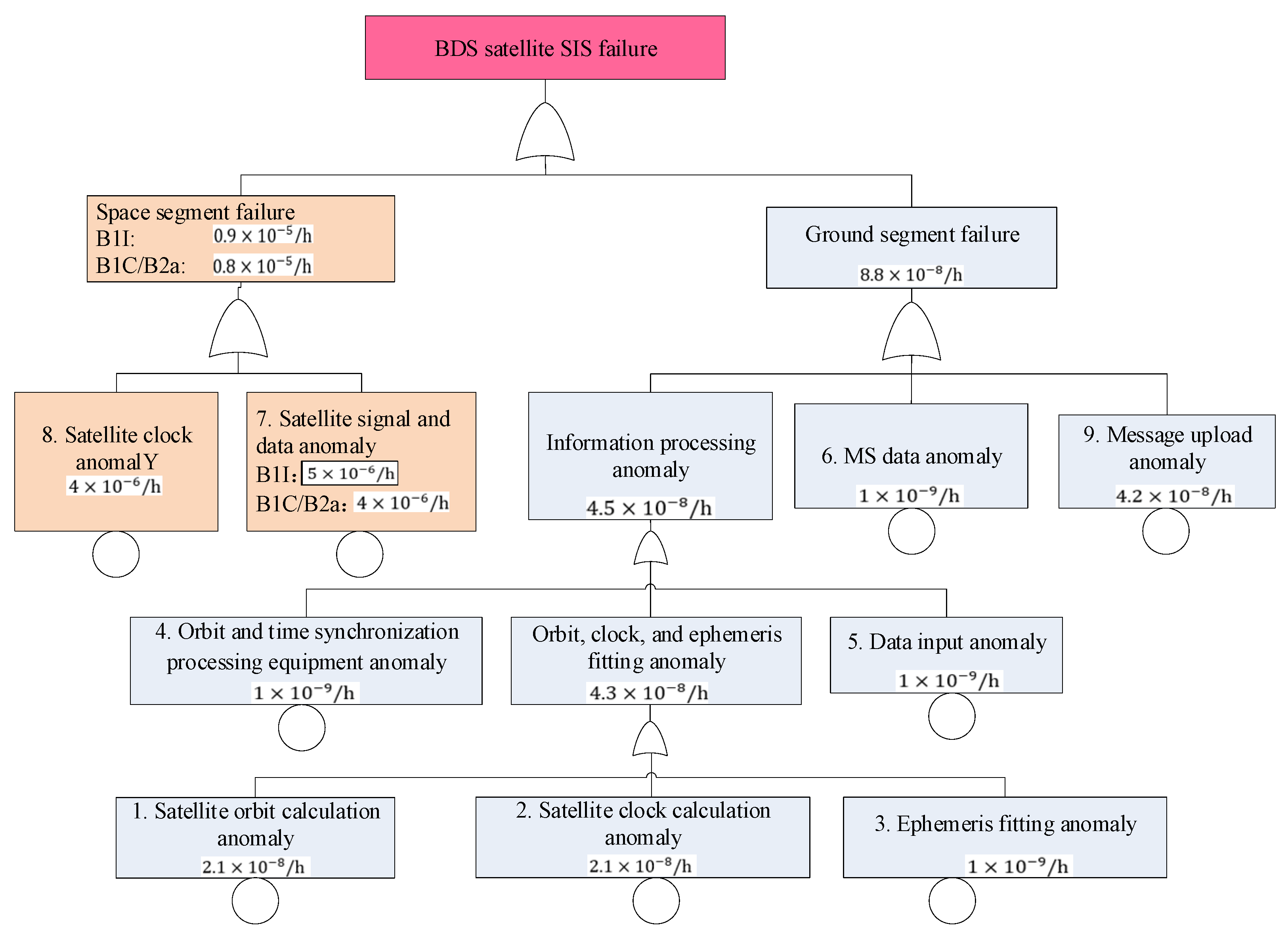
Based on the above-mentioned bottom events, an integrity risk tree can be constructed to systematically analyze and evaluate the satellite service failure probability of BDS, as shown in
Figure 1.
There are a total of nine bottom events in
Figure 1, including two in the space segment and seven in the ground segment. The probability of the top event is the known P
sat. The occurrence of each bottom event could lead to the occurrence of the top event. The relationship between them is a simple probability addition, which can be expressed as following:
where
denotes the probability of each bottom event in the integrity risk tree.
3.2. ModelBottom Event Probability
3.2.1. Bottom Event Probability for Space Segment
The failure probabilities of the two bottom events of the space segment are estimated as following:
For the B1I signal, the integrity failure mode and effect analysis (IFMEA) has been conducted on the operating status of the BDS-3 basic constellation (consisting of 18 BDS-3 satellites) since its completion on 27 December 2018, and no satellite signal and data anomaly events have been found during the assessment period. According to the design requirements of BDS-3, the probability of this anomaly is 5 × 10
−6/h, that is:
where indices 6, 7 refer to the bottom events 6, 7 in the integrity risk tree.
For the B1C and B2a signals, there has also been no satellite signal and data anomaly events occurred since 27 December 2018. According to the design requirements of BDS-3, the probability of such anomaly is 4 × 10
−6/h, that is:
where indices 6, 7 refer to the bottom events 6, 7 in the integrity risk tree.
- 2.
Satellite clock anomaly probability
The IFMEA has been conducted and no satellite clock anomaly events have been found. According to the internal system design requirements of BDS-3, the probability of such an anomaly is 4 × 10⁻⁶/h.
3.2.2. Bottom Event Probability for Ground Segment
The failure probabilities of the seven bottom events of the ground segment are estimated as following:
The IFMEA result shows that only one satellite orbit calculation anomaly event occurred since 27 December 2018, which was detected in time by the ground segment and did not affect the satellite SIS integrity. No satellite clock calculation anomaly event occurred during the assessment period.
Due to the similarities in the causes and mechanisms of these two types of bottom events, we assume that the average probability of each event is 0.5 times per year. Moreover, since the anomaly event can only affect the satellite SIS integrity when the system fails to detect it, we further assume that the missing alarm (MA) rate of the BDS-3 ground segment is 0.01. Thus, for the 24 MEOs and 3 IGSOs of BDS-3 (that is, the BDS-3 nominal constellation defined in ICAO SAPRs), the probabilities of these two anomalies can be determined as following:
where indices 1, 2 refer to the bottom events 1, 2 in the integrity risk tree.
- 2.
Bottom events 3, 4, 5, and 6 anomaly probability
The IFMEA result shows that none of these four anomaly events occurred since 27 December 2018. According to the internal system design requirements of BDS-3, the probabilities of these four anomalies are all 1 × 10
−9/h, that is:
where indices 3, 4, 5, 6 refer to the bottom events 3, 4, 5, 6 in the integrity risk tree.
- 3.
Message upload anomaly
The IFMEA result shows that only one message upload anomaly event occurred since 27 December 2018, which was detected in time by the ground segment and did not affect the satellite SIS integrity. Therefore, the probability of occurrence of this anomaly can be assumed to be 1 time per year.
Still assuming that the MA rate of the BDS-3 ground segment is 0.01, the probability of such anomaly can be determined as following:
where index 9 refers to the bottom event 9 in
Figure 1.
3.3. Design Values of Psat and Pconst
Table 5 shows the bottom event risk probability analysis results of the BDS satellite SIS integrity. The design value of P
sat is the sum of the design integrity risk probabilities of all the bottom events in
Table 3. For the B1I signal, the design P
sat is 0.9 × 10
−5/h; for the B1C and B2a signals, the design P
sat is 0.8 × 10
−5/h.
For the BDS constellation service failure, the bottom events include the Earth orientation parameters (EOPs) determination or prediction abnormality, the MS antenna phase center deviation, the MS hardware/software failure, the MCS hardware/software failure, the satellite orbit and clock calculation parameter failure, and the satellite design defects, etc.
Investigating the operation status of BDS-3 in 2019 revealed that no constellation service failure event occurred. In this paper, we make assumptions and conservative estimates. Assuming that the system has 0.5 constellation service failure events since 27 December 2018, then P
const can be estimated according to Equation (8) as following [
27,
28]:
where 1 h is the assumed MTTN.
4. Risk Prevention and Control
In order to reduce the risk probability of the integrity bottom events, it is necessary to take corresponding preventive and control measures in the system. This section introduces the failure/risk prevention and control measures taken in BDS-3 satellites and ground facilities, which mainly focus on software/hardware redundancy backup and signal/information monitoring and verification.
4.1. Space Segment Measures
From the analysis in
Section 3, it can be seen that the space segment is the part with the highest probability of BDS integrity risk. This is due to the complexity of the space environment in which the navigation satellite is located and the difficulty of operation caused by being far from the ground.
The BDS-3 satellite downlink navigation payload includes the time and frequency system, navigation signal generation, navigation signal broadcast, and antenna. In order to cope with possible integrity risks in the space segment, BDS-3 satellites have taken corresponding measures in various aspects.
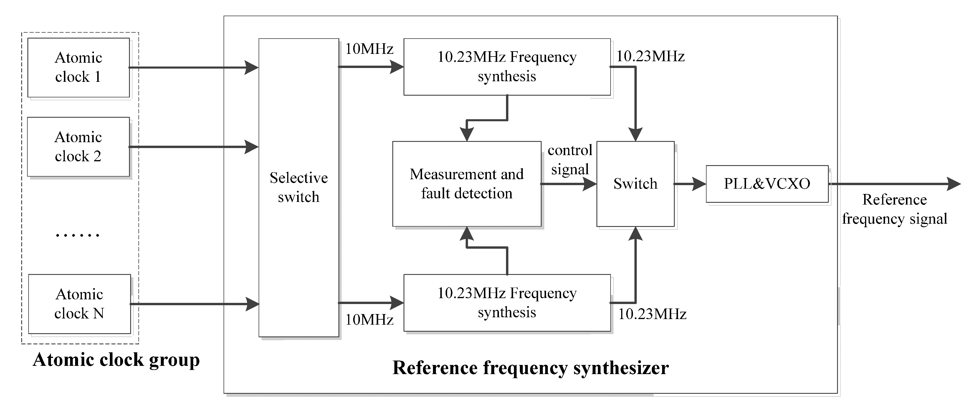
To prevent the satellite clock anomaly (Event 8 in
Figure 1), each satellite is equipped with multiple on-board atomic clocks, one of which is selected by the reference frequency synthesizer as the working clock, and the others as backups. The structure is shown in
Figure 2, in which the 10 MHz signal is the standard output frequency of the atomic clock, and the 10.23 MHz signal for the working and standby circuits is generated by the frequency synthesizer. When an abnormality occurs in the working clock, the measurement and fault detection module of the reference frequency synthesizer detects the abnormality in time and switches the output frequency to the hot standby circuit. To ensure a smooth signal transition before and after the switchover, the measurement and fault detection module synchronizes the frequency and phase of the 10.23 MHz signals of the hot standby and working circuits by means of a precision tracking algorithm, so that they remain synchronized at any time and the frequency and phase of the output signal can remain unchanged after the switchover.
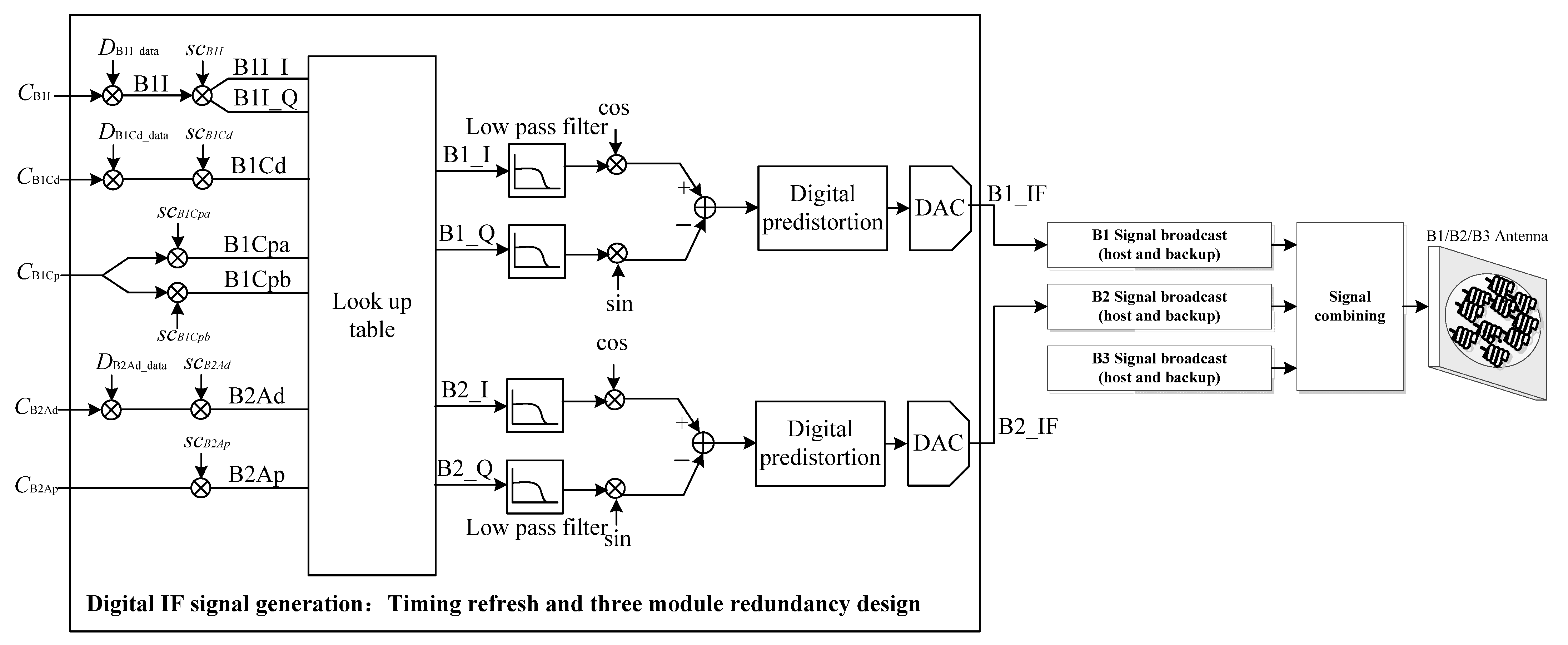
To prevent the satellite signal and data anomaly (Event-7 in
Figure 1), each satellite has a fault-proof design for the navigation signal generation and broadcast process, as shown in
Figure 3. In the digital intermediate frequency (IF) signal generation module, full triple modular redundancy (TMR) is designed for its look-up tables, registers, and processing modules, and a dedicated anti-fuse Field Programmable Gate Array (FPGA is used to refresh the TMR data at regular intervals to prevent single event upsets. For B1I, B1C, and B2a signals, the satellite has the ability to monitor and handle faults of relevant equipment on the broadcast channel, such as frequency modulators and power amplifiers, and switch to the other channel when a fault occurs in one path.
4.2. Ground Segment Measures
Although the risk probability of the ground segment is very low, once it occurs, it easily causes serious consequences and becomes the “gray rhino” in system operation and service. For example, the Galileo offline event of 2019 mentioned above was precisely caused by the “ground technology failure” according to the EUROPEAN GNSS AGENCY (GAS). More specifically, it is confirmed to be related to the abnormal behavior of a ground atomic clock in the time determination function of the system [
30,
31]. Therefore, it is very necessary to strengthen the prevention and control on the ground section.
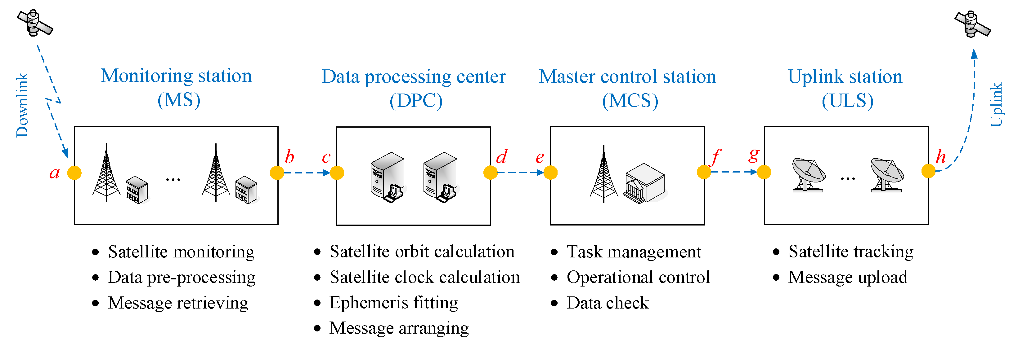
The composition of the BDS-3 ground segment and its processing flow can be simplified shown in
Figure 4. In order to deal with possible integrity risks, BDS-3 has taken corresponding measures in each processing link:
To prevent the MS data anomaly (Event 6 in
Figure 1), each MS is equipped with multiple monitoring receivers and atomic clocks to achieve redundancy.
To prevent the navigation message upload anomaly (Event-9 in
Figure 1), one measure is to implement a mutual backup strategy for the uplink station (ULS) antennas to prevent hardware failures; the other is to set up the monitoring function points before uploading and retrieving the navigation messages, respectively (see point a and point
h in
Figure 4).
To prevent the satellite orbit calculation anomaly, the satellite clock calculation anomaly, and the ephemeris fitting anomaly (Events 1–3 in
Figure 1), one measure is that the data processing center (DPC) has multiple channels for data calculation and generation, and they are independent of each other; the other is that the master control station (MCS) will check the correctness and validity of the products sent from the DPC.
To prevent the orbit and time processing equipment anomaly (Event 4 in
Figure 1), one measure is that the system is running both the main DPC and the backup DPC online at the same time; the other is that each DPC is equipped with multiple processing equipment to achieve redundancy.
To prevent the data input anomaly (Event 5 in
Figure 1), for all the aspects of data transmission involved in ground segment facilities, the monitoring function points are set up before data transmission and after data reception (see point
b to point
g in
Figure 4).
In addition, BDS-3 also introduces a third-party external monitoring system independent of its own ground segment, such as the international GNSS monitoring and assessment system (iGMAS), commercial receivers, and FPGA verification terminals to conduct continuous and real-time monitoring and evaluation of satellite SIS and messages. When an anomaly is found, these external systems will notify the MCS via a rapid alarm mechanism (for example, a private network).
6. Conclusions
This contribution focuses on the integrity concept design and construction of China’s BDS-3. Both the B1I signal and the B1C/B2a signal of BDS-3 have integrity functions. Among them, the B1I signal uses 4.42 times the URE as the NTE, and uses the SatH1 parameter in the D1 navigation message as the health status indicator; the B1C/B2a signal uses 4.42 times the SISA as the NTE, and uses the HS, SIF, and DIF parameters in the B-CNAV1/B- CVNV2 navigation message as the health status indicators. According to the nine integrity risk bottom events in the BDS-3 satellite SIS fault tree model, the Psat design values of the B1I and B1C/B2a signals are analyzed and determined to be 0.9 × 10⁻⁵ and 0.8 × 10⁻⁵, respectively, which both meet the ICAO’s performance requirement for the en-route flight operation (less than 1 × 10⁻⁵). The Pconst design value of BDS-3 is 6 × 10⁻⁵.
The integrity function of BDS-3 has two approaches, the ground monitoring and alarm, and the satellite monitoring and alarm, and the design TTA can reach 60 s and 6 s/300 s, respectively. Among them, the 6s rapid alert mechanism relies on the SAIM function, and BDS is still working hard to realize this capability as soon as possible.
The integrity risk analysis and verification results show that the actual operation of the system is consistent with the conceptual design requirement, and it satisfies the integrity performance promised by BDS-3 in the ICAO SAPRs. The performance of the system in actual operation and service proved the effectiveness of the BDS-3 integrity concept design and system prevention and control measures.


