Abstract
The DLR Earth Sensing Imaging Spectrometer (DESIS) is the first hyperspectral imaging spectrometer installed in the Multi-User System for Earth Sensing (MUSES) on the International Space Station (ISS) for acquiring routine science grade images from orbit. It was launched on 29 June 2018 and integrated into MUSES. DESIS measures energy in the spectral range of 400 to 1000 nm with high spatial and spectral resolution: 30 m and 2.55 nm, respectively. DESIS data should be sufficiently quantitative and accurate to use it for different applications and research. This work performs a radiometric evaluation of DESIS Level 1 product (Top of Atmosphere (TOA) reflectance) by comparing it with coincident Radiometric Calibration Network (RadCalNet) measurements at Railroad Valley Playa (RVUS), Gobabeb (GONA), and La Crau (LCFR). RVUS, GONA, and LCFR offer 4, 15, and 5 coincident datasets between DESIS and RadCalNet measurements, respectively. The results show an agreement between DESIS and RadCalNet TOA reflectance within ~5% for most spectral regions. However, there is an additional ~5% disagreement across the wavelengths affected by water vapor absorption and atmospheric scattering. Among the three RadCalNet sites, RVUS and GONA show a similar measurement disagreement with DESIS of ~5%, while LCFR differs by ~10%. Agreement between DESIS and RadCalNet measurements is variable across all three sites, likely due to surface type differences. DESIS and RadCalNet agreement show a precision of ~2.5%, 4%, and 7% at RVUS, GONA, and LCFR, respectively. RVUS and GONA, which have a similar surface type, sand, have a similar level of radiometric accuracy and precision, whereas LCFR, which consists of sparse vegetation, has lower accuracy and precision. The observed precision of DESIS Level 1 products from all the sites, especially LCFR, can be improved with a better Bidirectional Reflection Distribution Function (BRDF) characterization of the RadCalNet sites.
1. Introduction
Satellite remote sensing has played a vital role in monitoring and quantifying the changes on the Earth’s surface and its atmosphere at a regional, continental, and global scale. Multispectral sensors such as Landsat and other sensors have been providing spectral, spatial, and temporal information for several decades and have been improving the understanding of surface and atmospheric changes. However, there is always a demand for more information in the spectral, spatial, and temporal domains in order to enhance the current understanding and explore new applications. A recent survey conducted across a diverse range of scientific research and application domains shows that spectral, spatial, and temporal improvements to the current Landsat sensor would broadly benefit applications across ecosystems, agriculture, forestry, disaster response, human health, climate, ocean, coastal, and inland water resources monitoring among others [1]. The study shows that users want weekly cloud-free observations, increased spatial resolution, i.e., 10 m, and multiple narrow spectral bands in visible, near-infrared, and thermal regions that are needed for agriculture, forestry, mineral resources, and human health applications. The same study shows that users ideally desire sub-weekly to daily cloud-free observations, higher reflective spatial resolution at 5 m, and continuous 10 nm width spectral capability (hyperspectral imaging) over the solar reflective region. Hyperspectral imaging offers a plethora of spectral information that makes it a very powerful dataset for improving the accuracy of current applications and for exploring new applications across different domains such as geoscience, natural hazards, vegetation characterization, water application, cryosphere, and landcover mapping, among others [1,2,3,4].
Hyperspectral imaging records energy from contiguous spectral bands over a defined wavelength for each pixel. It contains information from very narrow spectral regions and offers scientists an opportunity to study finer spectral details than those available from multispectral sensors. Hyperspectral imaging of the Earth surface started in 2000 with the launch of Earth Observing (EO-1) Hyperion. It was the first high spatial resolution space-based imaging spectrometer to acquire science-grade data from orbit, which has enabled scientists to explore new methods and algorithms to characterize the Earth’s surface [5]. After 17 years in orbit, it was decommissioned on 30 March 2017. Production of an imaging spectrometer with high spectral, spatial, and high signal to noise ratio (SNR) is very challenging because as the spectral bandwidth decreases, a large amount of energy is required by the detectors to achieve a sufficient SNR [2]. In addition to sensor limitations, hyperspectral detection produces large volumes of data, which makes handling datasets somewhat challenging. However, due to advancements in technology, data computation required for the handling of large volume hyperspectral datasets, and the value those datasets bring to the remote sensing community, more hyperspectral missions are in space than in previous decades. Currently, there are several ongoing hyperspectral missions such as the Indian Hyperspectral Imaging Satellite (HySIS) and the Italian PRecursore IperSpettrale della Missione Applicativa (PRISMA) missions [6], which are in sun-synchronous orbits. Similarly, ISS is also hosting several hyperspectral missions such as the Japanese Hyperspectral Imager Suite (HISUI) imager [7], DESIS [2], and soon NASA’s Climate Absolute Radiance and Refractivity Observatory (CLARREO) Pathfinder mission [8]. DESIS is the first hyperspectral imaging spectrometer integrated into the (MUSES) platform on the ISS. It has 235 spectral channels recording imaging from visible to near infrared region (400 nm to 1000 nm) with spectral sampling of ~2.55 nm. Its ground sample distance (GSD) or pixel size is ~30 m and the image size is 30 km × 30 km. More technical details of DESIS are described in Section 2.1. As the number of space-based hyperspectral imaging spectrometers are limited, DESIS hyperspectral data are crucial for improving the current understanding of different applications.
DESIS data should be quantitative and accurate for scientific applications and for characterization of real-world problems. Understanding its radiometric data quality will benefit the broader scientific community. In addition, DESIS data improve understanding of the bidirectional reflectance distribution function (BRDF) of the surface. As DESIS is installed on the ISS, it can image locations on the Earth with varying viewing and illumination geometry which helps to understand these angular effects and ultimately minimize them in remote sensing data. Similarly, DESIS can be used to compute the spectral band adjustment factor (SBAF), a factor used to compensate the intrinsic differences between two multispectral sensors that arise due to different relative spectral response (RSR) functions that affect sensor cross comparison and sensor harmonization [9,10]. DESIS is unique due to its high spectral sampling, SNR of approximately 200, and multi-angular capability. These salient characteristics offer different and new opportunities compared to previous and existing hyperspectral missions in both spectral and angular domains, so it is crucial to understand its radiometric quality.
Radiometric evaluation of optical satellite sensors is performed by using several techniques such as the reflectance/radiance-based vicarious approach [5,11,12], cross-comparison with other well-calibrated sensors [13], and lunar acquisition comparison [5]. Among all the techniques, the reflectance/radiance vicarious approach has been widely used to evaluate radiometric performance of optical satellite sensors due to a lower uncertainty. Reflectance/radiance vicarious calibration requires an accurate reflectance measurement of the surface and accurate measurement of atmospheric parameters such as aerosol and water vapor during sensor overpass of the surface [11]. The surface reflectance and the corresponding atmospheric parameters are used as inputs to a radiative transfer code to predict Top of Atmosphere (TOA) reflectance. Radiometric evaluation of the sensor of interest is performed by comparing the TOA reflectance measured by the sensor with the predicted TOA reflectance. One of the major limitations of this approach is the lack of sufficient datasets due to their labor-intensive nature and expense as scientists are typically required to be physically present at the selected site/time of the overpass to measure the surface and atmospheric parameters. However, recent development of automated sites to collect surface and atmospheric measurements, known as the RadCalNet, has helped to ease the labor-intensive process and also increase the number of datasets for sensor radiometric evaluation [14]. More details about RadCalNet are presented in Section 2.2.
The major focus of this paper is to perform a radiometric evaluation of DESIS hyperspectral data using the reflectance/radiance-based vicarious approach, i.e., comparing DESIS measurements with RadCalNet in situ measurements. This paper is organized as follows. Section 2 provides an overview of DESIS technical specification and RadCalNet, Section 3 provides the data and methodology used to perform this work, Section 4 shows results and presents the discussion, and Section 5 provides the conclusion of this work.
2. DESIS and RadCalNet Overview
2.1. DESIS
DESIS was launched on June 29, 2018 and is mounted on the Multi-User System for Earth Sensing (MUSES) platform on the ISS. DESIS is a collaboration between German Aerospace Center (DLR) and Teledyne Brown Engineering (TBE). It is the first high-resolution visible–near-infrared (VNIR) hyperspectral imaging spectrometer installed on the platform. It has 235 spectral channels recording imaging from visible to near infrared region (400–1000 nm) with spectral sampling of ~2.55 nm. Its ground sample distance (GSD) or pixel size is ~30 m and the image size is 30 km × 30 km. DESIS is installed in non-synchronous orbit and it has off-nadir capacity of up to ±15° along track and the platform also has an ability to look ±25° along the track which enables it to image the Earth’s surface from different viewing and solar geometry. An overview of DESIS technical details is listed in Table 1 [15,16].

Table 1.
DESIS Salient Features.
2.2. RadCalNet
RadCalNet data are used for post-launch calibration of optical satellite systems. RadCalNet is an effort by the RadCalNet Working Group of the Committee of Earth Observation (CEOS) Working Group on Calibration and Validation (WGCV) Infrared and Visible Optical Sensors Subgroup (IVOS). Its main goal is to facilitate reflectance-based vicarious calibration of optical sensors ranging from visible to shortwave infrared wavelength by automating and providing in situ surface and atmosphere measurements at different sites [14]. The reflectance-based calibration approach, despite having traceable absolute uncertainty [17], lacks precision due to the limited number of data collections available. An automated approach like RadCalNet can help overcome the caveats of vicarious calibration and increase accuracy of radiometric calibration of optical satellite sensors. RadCalNet provides International System of Units (SI)-traceable TOA reflectance for a nadir view in 30 min intervals between 9:00 AM and 3:00 PM local time for a given site. The TOA reflectance ranges from 400 nm to 2500 nm with spectral sampling of 10 nm [14]. The TOA reflectance of a given site is predicted by a radiative transfer code using nadir surface measurements coupled with atmospheric parameters such as surface pressure, water vapor, ozone, aerosol optical depth, and Angstrom coefficient measurements.
There are five RadCalNet sites: Railroad Valley Playa (RVUS) in USA, Gobabeb in Namibia, La Crau (LCFR) in France, Baotau (BTCN), and Baotau sand (BSCN) in China. Each of the RadCalNet sites are discussed briefly in the following subsections.
2.2.1. Railroad Valley Playa
Railroad Valley Playa has been frequently used for radiometric calibration of optical satellite sensors for several decades [11]. It is in Nevada, USA, and managed by University of Arizona. The site is a clay-based playa homogeneous in nature as shown in Figure 1. The reflectance on RVUS represents a 1 km × 1 km surface centered at 38.497° N and 11.690° W as shown by a red solid rectangle in Figure 1a. The surface reflectance is generally stable under dry conditions and approximately Lambertian for viewing angles within 30° [18] and has a low yearly average aerosol on the order of 0.060 at 550 nm [19]. The uncertainty associated with RVUS RadCalNet site surface reflectance ranges from 3.5% to 5.3% [20].
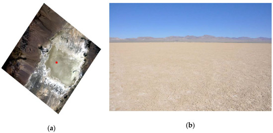
Figure 1.
DESIS image of Railroad Valley Playa (a) and site view (b).
2.2.2. Gobabeb
Gobabeb is in the Namib-Naukluft National Park in Namibia. This RadCalNet site is operated jointly by the European Space Agency (ESA) and the French Space Agency Centre National d’études Spatiales (CNES). Its surface type includes sand and gravel and looks homogeneous in nature as shown in Figure 1b. The reflectance on Gobabeb (GONA) represents an approximately 1 km × 1 km area centered at 23.612° S and 15.120° E as shown by a red solid rectangle in Figure 2a. The average aerosol optical depth at 550 nm at this site is approximately 0.1. Its working group reported the surface reflectance uncertainty for this site for clear sky conditions ranges from 3.5% to 4% which increases by an additional 1% for a turbid day. BRDF effects at this site are expected to be minimal as the surface type is predominantly sand.
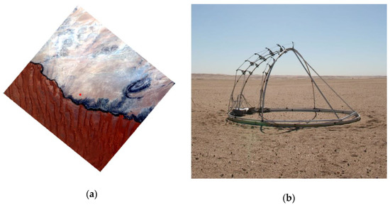
Figure 2.
DESIS image of Gobabeb (a) and site view (b).
2.2.3. La Crau
La Crau site has been used since 1987 for vicarious calibration [21]. It is situated in the regional park Reserve Naturelle des Coussouls de Crau in southeastern France. Its geographical coordinate is 4.87° E and 43.50° N and is 20 m in altitude as shown in Figure 3a [14,22,23]. The La Crau site is a flat surface and has a thin pebbly soil with sparse vegetation as shown in Figure 3b. This site is also operated and maintained by CNES. The aerosol optical depth at 550 nm at this site ranges from 0.01 to 0.5 with its average value being approximately 0.15. The uncertainty associated with the surface reflectance of this site ranges from 3.5% to 5% depending on the spectral band [22].
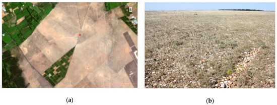
Figure 3.
DESIS image of La Crau (a) and site view (b).
2.2.4. Baotau Sand
The Baotau calibration site is located in Inner Mongolia, China, 50 km away from Baotau city [24,25]. This location has two RadCalNet sites: the first one is an artificial target [26] (BTCN) at 40.8514° N, 109.6292° E and the second one is a natural target (BSCN) at 40.8658° N, 109.6155° E with an altitude of 1270 m. The spatial extent of the homogenous region at BTCN is 48 m × 48 m which is not enough to avoid adjacency effects for sensors like DESIS which has a GSD of 30 m. Adjacency effect is the noise in the targeted pixel due to scattering signal from its surrounding pixels.
The second RadCalNet site at Baotau (BSCN) includes sand as shown in Figure 4a,b. Both sites are operated and maintained by Chinese Academy of Science. The average aerosol optical depth at 550 nm on BSCN is approximately 0.25. The uncertainty of TOA reflectance for BSCN is approximately 4–5% [25].
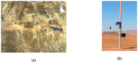
Figure 4.
DESIS image of Baotau (a) and site view (b).
3. Materials and Methods
This section describes the methodology used for this study. It includes finding coincident acquisitions between DESIS and RadCalNet sites and filtering for cloudy scenes. Cloud-free coincident DESIS scenes are used to extract TOA reflectance from the selected region of interest (ROI) for comparison with RadCalNet data.
3.1. Data Selection
DESIS radiometric performance was evaluated using four RadCalNet sites: RVUS, GONA, LCFR, and BSCN. This evaluation includes measurements from November 2018 to September 2020. The coincident dates between DESIS imaged RadCalNet sites are listed in Table 2. Table 2 shows that RVUS, GONA, LCFR, and BSCN have 22, 17, 12, and 3 opportunities for comparing DESIS measurements with RadCalNet measurements, respectively. DESIS images corresponding to these data were downloaded from https://teledyne.tcloudhost.com/ (accessed on 12 March 2021), whereas RadCalNet measurements were downloaded from RadCalNet portal. Bold dates of Table 2 have RadCalNet measurements all day long from 9:00 AM to 3:00 PM whereas other dates have RadCalNet measurements during certain times of the day.

Table 2.
DESIS acquisition dates (yyyy.mm.dd) at RadCalNet Sites. Bold dates are the dates when RadCalNet has measurement all day long from 9:00 AM to 3:00 PM, whereas other dates have RadCalNet measurement at certain times of the day.
3.2. Data Screening
Data screening was performed to remove noise in the analysis. The first filter was a cloud filter, and all downloaded images were visually inspected for cloud and shadow. Only cloud and shadow-free images were used in this study. The second filter was DESIS acquisition time. DESIS is installed on ISS, so it images RadCalNet sites at different times of the day, whereas RadCalNet only takes measurements from 9:00 AM to 3:00 PM local time. Only DESIS images coincident with RadCalNet measurements were processed for further study.
3.3. Image Region of Interest (ROI) Extraction
DESIS spectra were extracted from the selected region of interest for all RadCalNet sites. The selected ROIs were centered at latitude and longitude coordinates provided by RadCalNet. As DESIS has a GSD of 30 m and geolocation accuracy of about one pixel [2], an ROI size of 23 pixels × 23 pixels (~690 m × ~690 m) was chosen to extract the representative spectrum from RVUS. Similarly, an ROI of size 15 pixels × 15 pixels (~450 m × ~450 m) and 4 pixels × 4 pixels (~120 m × ~120 m) were chosen for GONA and LCFR, respectively. The ROI size was determined by visual inspection with an attempt to include a large homogeneous region in order to minimize geolocation misregistration effects. ROI selection at Baotau sand (BTCN) is not discussed here as it was not used for this analysis because its RadCalNet measurements had no valid measurements during the DESIS overpasses.
3.4. Conversion to TOA Reflectance
The DESIS image data were converted to reflectance as follows:
where is the spectral radiance at the sensor’s aperture; and are the band specific multiplicative and additive scaling factors, respectively, obtained from the associated product metadata; DN is a numerical value corresponding to the recorded electromagnetic energy at each pixel; d is the Earth–sun distance in astronomical units; and is the solar zenith angle during image acquisition obtained from the associated product metadata. is Thuillier solar exoatmospheric irradiance.
RadCalNet data are already expressed in TOA reflectance units.
4. Results
This section shows a comparison between DESIS and RadCalNet over the three RadCalNet sites. The comparison was performed using coincident cloud-free DESIS scenes and RadCalNet measurements acquired from November 2018 to September 2020.
4.1. Comparison on Railroad Valley Playa (RVUS)
RVUS had four coincident acquisitions between DESIS and RadCalNet measurements as shown in Figure 5. In the figure, blue symbols represent DESIS viewing geometry, red symbols represent solar geometry during DESIS acquisitions, and black symbols represent solar geometry during RadCalNet acquisitions. All the comparison datasets were collected between 10:00 AM and 3:00 PM local time. For the comparison of datasets at RVUS, DESIS view zenith angle ranges from nadir to 4°, whereas the view azimuth had two approximate values: 56° and 123°. View azimuth angle of 56° corresponds to its ascending mode in the orbit, similarly, 123° view azimuth angle corresponds to its descending mode. The difference in solar geometry during DESIS acquisition and RadCalNet measurement is within 1° as the time difference between the measurements is less than 14 min. Minimal solar geometry difference minimizes angular effects on the TOA reflectance and helps to improve DESIS radiometric characterization.
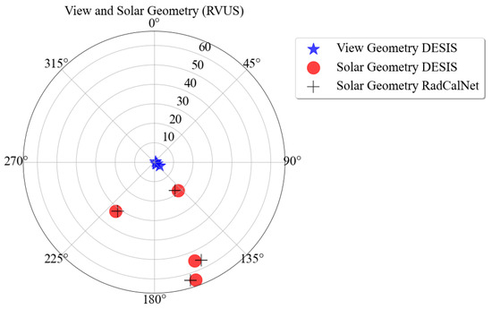
Figure 5.
Acquisition geometry on RVUS. Blue symbols represent DESIS viewing geometry, red symbols represent DESIS solar geometry, and black symbols represent RadCalNet solar geometry.
Figure 6a shows RVUS TOA reflectance using RadCalNet with 1-sigma standard deviation. The standard deviation represents the associated uncertainty with the spectrum provided by RadCalNet technical working group [20] which is approximately 4% for all spectra shown in Figure 6a. The variation in TOA reflectance is due to seasonal variation as these spectra are acquired at different times of the year. The sharp decrease in TOA reflectance at approximately 760 nm and 940 nm is because of absorption due to water vapor. Results at these channels are unreliable due to the combined effects from low signal from both systems and high sensitivity to atmospheric characterization [5].
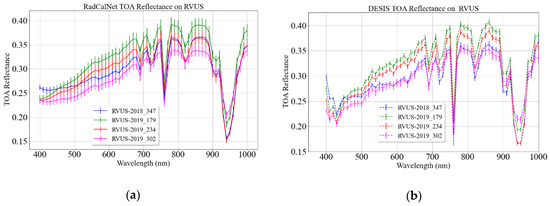
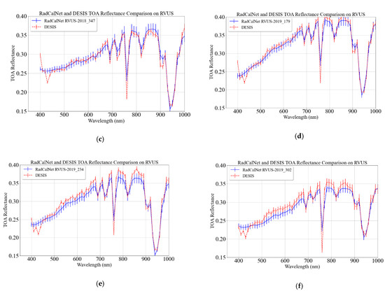
Figure 6.
RVUS TOA reflectance, RadCalNet (a) and DESIS (b). RadCalNet and DESIS individual spectrum comparison (c–f). DESIS acquisition dates and RadCalNet measurement dates are expressed in (yyyy_day of year).
Similarly, Figure 6b shows DESIS TOA reflectance on RVUS with 1-sigma standard deviation. The associated standard deviation represents the spatial variation of the selected ROI which was 2% for all spectra. DESIS TOA reflectance is similar to RadCalNet TOA reflectance for the majority of the spectral regions; however, DESIS spectra are inconsistent at shorter wavelengths, typically at wavelengths less than 430 nm, due to atmospheric scattering. Figure 6c–f shows a comparison between individual coincident DESIS and RadCalNet spectrum.
Figure 7a shows the normalized DESIS TOA reflectance; these spectra are normalized, by dividing DESIS TOA reflectance using coincident RadCalNet measurements, for better visualization. DESIS agrees with the RadCalNet measurements within approximately 1–6% for most of the spectral regions. Wavelengths between 600 nm to 700 nm show the best agreement (i.e., within 1% and 4%), whereas wavelengths between 500 nm and 600 nm show an agreement between 2% and 6%. Between 800 nm to 1000 nm, the agreement between the two systems is 2% and 8%.
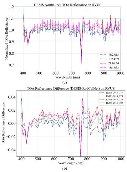
Figure 7.
DESIS normalized TOA reflectance on RVUS (a). Absolute TOA difference between DESIS and RadCalNet TOA reflectance (b).
Figure 7b shows DESIS and RadCalNet TOA reflectance difference in absolute scale. The TOA reflectance difference between these systems is within 0.02 reflectance units for wavelength ranges from 430 nm to 1000 nm; however, the discrepancies between the two systems are as large as 0.04 reflectance unit for wavelengths less than 430 nm.
Figure 8 shows the overall agreement between DESIS and RadCalNet TOA reflectance. The blue curve represents the mean of normalized DESIS TOA reflectance where error bars represent its associated 1-sigma standard deviation. DESIS agrees with RadCalNet within 4% for the majority of spectral regions with the exception of wavelengths less than 430 nm which vary by up to 8%. A convenient way to find the consistency of the agreement is to find the standard deviation of the mean shown by the red curve in Figure 8. Excluding the shorter wavelengths and spectral regions highly effected by water vapor absorption, normalized DESIS TOA reflectance is consistent within 2% for wavelengths less than 700 nm and within 3% for the wavelengths greater than 700 nm.
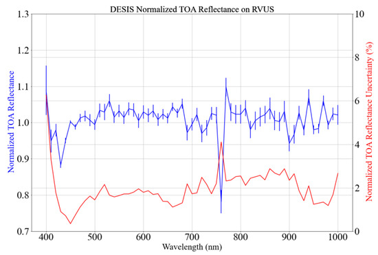
Figure 8.
Mean and standard deviation of 4 normalized DESIS TOA reflectance datasets shown in Figure 7a.
4.2. Comparison on GONA
Figure 9 shows the DESIS and RadCalNet coincident collects acquisition geometry on GONA. GONA offers 15 coincident collects within the study period that were used to perform the DESIS radiometric evaluation. DESIS has six descending and nine ascending mode acquisitions. These datasets were collected from 9:00 AM to 3:00 PM local time which encompasses a wide range of solar zenith and azimuth angles at the acquisition site. Solar zenith and azimuth angles range from 13.80° to 61.48° and 14.51° to 348°, respectively, as shown in Figure 9. Similarly, DESIS view zenith angles range from 0.43° to 21°. Additionally, view azimuth angles have two values, 42° and 137°, corresponding to DESIS ascending and descending mode acquisitions, respectively. The spectra for all these geometries are shown in Figure 10.
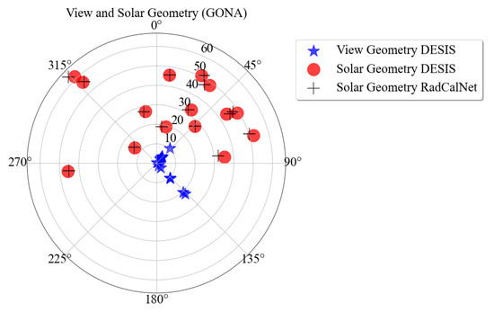
Figure 9.
DESIS and RadCalNet acquisition geometry on GONA. The blue symbols represent DESIS viewing geometry, the red symbols represent DESIS solar geometry, and the black symbols represent RadCalNet solar geometry.
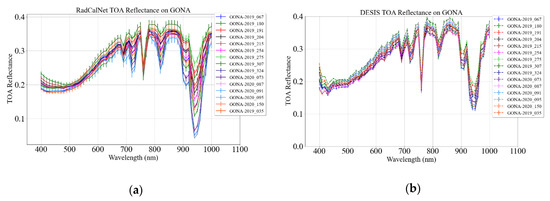
Figure 10.
GONA TOA reflectance: RadCalNet (a) and DESIS (b).
Figure 10a shows GONA TOA reflectance using RadCalNet with 1-sigma standard deviation. The standard deviation was provided by the RadCalNet working group [27] and is 4% for most of the spectral regions. GONA TOA reflectance spectra are similar with each other for the majority of spectral regions despite different viewing and solar geometries. However, TOA reflectance variation at shorter wavelengths (<500 nm) ranges from 0.18 to 0.23 reflectance units.
Figure 10b shows DESIS TOA reflectance on GONA with 1-sigma standard deviation. The standard deviation represents a spatial variation of the selected ROI. The standard deviation of the DESIS TOA reflectance is within 2% for all the spectral regions except for absorption regions at wavelengths greater than 940 nm. DESIS TOA reflectance looks similar to the RadCalNet-predicted TOA reflectance for the majority of the spectral regions except for wavelengths less than approximately 500 nm. TOA reflectance at the shorter wavelengths (<500 nm) ranges from 0.16 to 0.25 reflectance units.
Figure 11a shows DESIS normalized TOA reflectance on GONA. DESIS normalized TOA reflectance agrees with RadCalNet TOA reflectance within 3% and 10% except for the spectral regions affected by atmospheric absorptions features, i.e., 760 nm and 940 nm, and atmospheric aerosols, i.e., <430 nm. The DESIS spectra, such as the one represented by the blue solid curve (GONA-2019_067) in Figure 11a, agree with RadCalNet within 4% across most of spectral regions whereas the spectrum represented by the light blue-dashed curve (GONA-2020_091) represents the worst agreement case between the two systems which ranges beyond 10% for most of the spectral regions. However, most of the DESIS normalized TOA reflectance agrees with RadCalNet measurements within 6%. DESIS spectra have the best agreement with RadCalNet measurements for wavelengths between 600 nm and 700 nm, i.e., within 4%, and within 6% for wavelengths ranging from 550 nm to 600 nm.
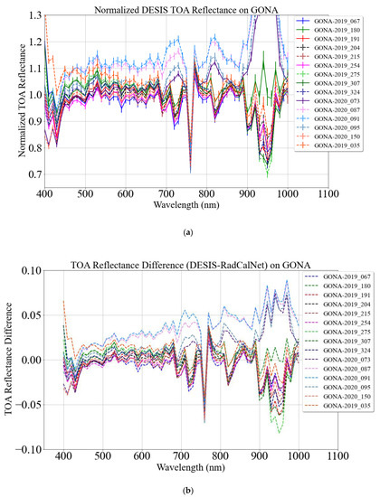
Figure 11.
DESIS normalized TOA reflectance on GONA (a). Absolute TOA difference between DESIS and RadCalNet TOA reflectance (b).
Figure 11b shows an absolute difference between DESIS and RadCalNet TOA reflectance. TOA reflectance difference is approximately 0.02 reflectance units and consistent across most of the spectral regions with a few exceptions up to 0.04 reflectance units. The blue-dashed curve in Figure 11b shows the minimum TOA reflectance difference between the two systems, i.e., within 0.01 reflectance units, for most of the spectral regions, whereas the light blue dashed curve represents the maximum difference which is more than 0.04 at the longer wavelengths.
Figure 12 shows an overall agreement between DESIS and RadCalNet TOA reflectance. The blue curve represents the mean of 15 normalized DESIS TOA reflectance measurements shown in Figure 11a, and the red curve represents the associated uncertainty. DESIS agrees with RadCalNet within 5% for wavelengths greater than 430 nm and 10% for wavelengths less than 430 nm. The larger discrepancies for the wavelengths less than 430 nm occur because DESIS measures less signal at those wavelengths than the predicted TOA reflectance. The mean DESIS normalized TOA reflectance is consistent within 4% for the wavelengths greater than 430 nm and increases exponentially for the wavelengths less than 430 nm.
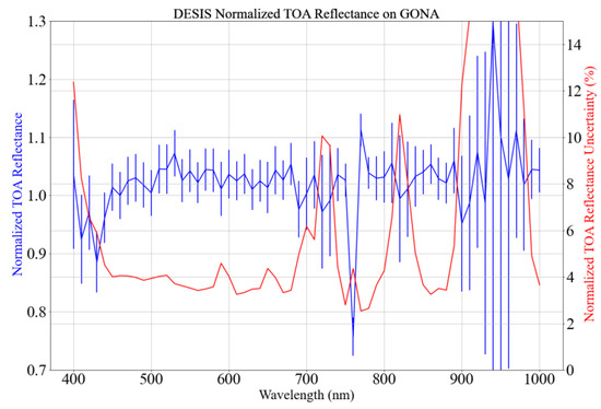
Figure 12.
Mean and standard deviation of 15 normalized DESIS TOA reflectance shown in Figure 11a.
4.3. Comparison on LCFR
Figure 13 shows DESIS viewing geometry and solar geometry during DESIS and RadCalNet acquisitions on LCFR. LCFR offers six coincident collects that can be used to perform DESIS radiometric evaluation. These datasets were collected from 9:00 AM to 3:00 PM local time. Variable acquisition time results in a wide range of solar angles; solar zenith angles ranged from 33.20° to 67.16°, and solar azimuth angles ranged from 117.27° to 247.28°. The difference in solar zenith and azimuth angles was less than 2.5° and 3°, respectively, as the datasets were coincident with the RadCalNet collects. Similarly, DESIS view zenith angle ranged from 3.15° to 17.42°, whereas view azimuth angles were approximately 64° and 115°, corresponding to its ascending and descending mode acquisitions.
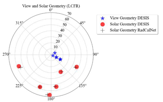
Figure 13.
DESIS and RadCalNet acquisition geometry on LCFR. The blue and red symbols represent DESIS viewing and solar geometry, respectively. The black symbols represent RadCalNet solar geometry.
Figure 14a,b shows RadCalNet and DESIS TOA reflectance on LCFR with 1-sigma standard deviation, respectively. The standard deviation was provided by the RadCalNet working group and is 5% [27], whereas the standard deviation associated with DESIS TOA reflectance represents the spatial uncertainty of the selected ROI and is within 2%. Both figures show that the LCFR site has two distinct spectral profile types. The first spectral profile, represented by the magenta curve (2020_228), is most similar to the spectral profile of sand or bare soil, whereas the second type, represented by all remaining curves, is similar to a vegetation spectral profile. DESIS and RadCalNet TOA reflectances appear similar to each other except for the shorter wavelengths less than 500 nm where DESIS TOA reflectance measures less signal then the RadCalNet prediction. DESIS TOA reflectance at these shorter wavelengths ranges from 0.13 to 0.18 reflectance unit, whereas RadCalNet TOA reflectance ranges from 0.15 to 0.20 reflectance units.
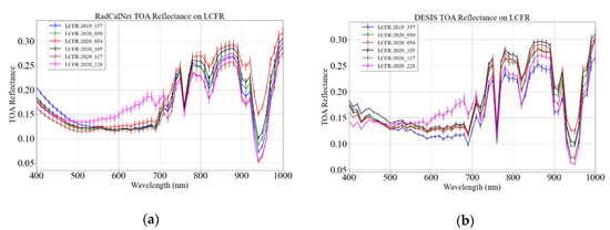
Figure 14.
LCFR TOA reflectance, RadCalNet (a) and DESIS (b).
Figure 15a shows the DESIS normalized TOA reflectance on LCFR. The normalized reflectance is more variable than observed in the previous two sites: RVUS and GONA. DESIS agrees with the RadCalNet measurement in a range from 5 to 20% as shown in Figure 15a. The magenta curve (LCFR-2020_228) shows the best agreement between the two systems, which is within 5% for the majority of the spectral regions. The brown curve (LCFR-2020_117) shows the largest discrepancies, which is within 12% for wavelengths ranging from 600 nm to 700 nm; however, it differs by up to 20% for all other spectral regions.
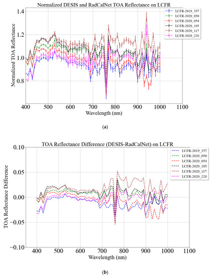
Figure 15.
DESIS normalized TOA reflectance on LCFR (a). Absolute TOA difference between DESIS and RadCalNet TOA reflectance (b).
Figure 15b shows DESIS and RadCalNet TOA reflectance difference in absolute reflectance units. The TOA reflectance differs within 0.02 reflectance units for most of the spectral regions, except for wavelengths less than 430 nm and spectral regions affected by atmospheric absorption.
Figure 16 shows overall agreement between DESIS and RadCalNet using coincident collects on LCFR. The blue curve represents the DESIS normalized TOA reflectance mean with 1-sigma error bars which are expressed in relative terms by the red curve. Figure 16 shows that DESIS agrees with RadCalNet within 5% for wavelengths from 600 nm to 700 nm whereas the agreement is within 10% for the rest of the spectral regions. Similarly, the normalized DESIS TOA reflectance uncertainty mostly resides within 6 and 7% depending on the spectral region.
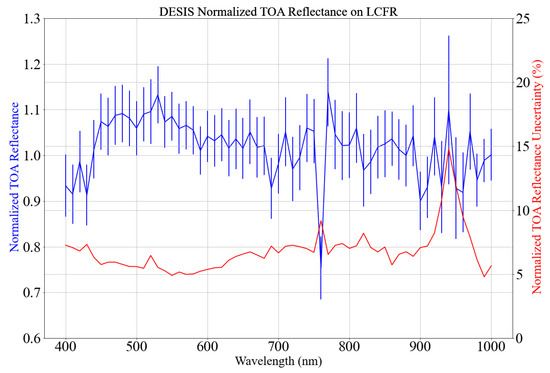
Figure 16.
Mean and standard deviation of 6 normalized DESIS TOA reflectance shown in Figure 15a.
4.4. Comparison Using All Sites
Figure 17 shows overall agreement between DESIS and RadCalNet measurement using coincident collects from all three sites: RVUS, GONA, and LCFR. The blue curve represents the DESIS normalized TOA reflectance mean, from all three sites, with 1-sigma error bar which are expressed in relative terms represented by the red curve. DESIS agrees with RadCalNet measurements within 5% for the wavelengths ranging from 430 nm to 700 nm with additional discrepancies for the wavelengths impacted by either atmospheric absorption features (wavelengths > 700 nm) or atmospheric scattering (wavelengths < 430 nm). Similarly, the normalized DESIS TOA reflectance uncertainty is within 5% for wavelengths ranging from 450 nm to 700 nm with an additional uncertainty for the remaining spectral regions as shown by red curve in Figure 17.
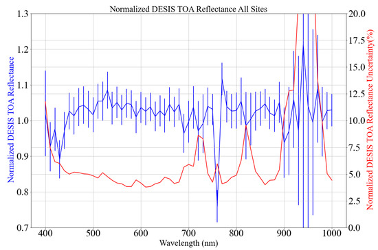
Figure 17.
Mean and standard deviation of normalized DESIS TOA reflectance from all sites.
4.5. Comparison Using All Sites and Only Desert Sites
Figure 18a shows a comparison between DESIS and RadCalNet TOA reflectance measurements using different surface types. Among the three RalCalNet sites used in this study, RVUS and GONA were desert, whereas LCFR surface consists of sparse vegetation. The blue and red curves represent the DESIS normalized TOA reflectance using datasets from all three sites and only desert sites, respectively. The corresponding uncertainty is shown in Figure 18b. DESIS normalized TOA reflectance shows 5% agreement with RadCalNet measurements coincident to deserts only, while agreement extended to 6% for measurements including all three sites. The consistency of normalized DESIS TOA reflectance calculated using desert sites only, i.e., RVUS and GONA, is within 4% for the majority of the spectral regions whereas the consistency of the normalized TOA reflectance calculated using all three sites is within 5%.
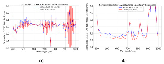
Figure 18.
Mean of normalized DESIS TOA reflectance using different sites (a) and its corresponding uncertainty (b).
5. Discussion
DESIS brings new and different opportunities to the remote sensing community than offered by previous and existing hyperspectral sensors such as EO-1 Hyperion and PRISMA, so it is of prime interest to understand its radiometric quality for the benefits of the community. Its radiometric quality was evaluated by comparing its measurements with coincident RadCalNet measurements from three RadCalNet sites, i.e., RVUS, GONA, and LCFR. Table 1 shows that RVUS, GONA, and LCFR had 22, 17, and 12 coincident opportunities, respectively; however, only 4 from RVUS, 15 from GONA, and 5 from LCFR were used for DESIS radiometric comparison in this study. Baotau sand (BSCN) was not used for this analysis as its RadCalNet measurements had no valid measurements during the DESIS overpasses. Even though 24 coincident datasets provided statistical confidence in accuracy of the method [28], there is a significant reduction in usable coincident opportunities due to RadCalNet invalid measurements and DESIS acquisition times. RadCalNet regularly measures the surface reflectance from 9:00 AM to 3:00 PM local time every 30 min, but the measurements are not always valid. Additionally, DESIS is installed on the ISS in non-sun-synchronous orbit resulting in imaging a particular location at different times during the day. There were several occasions where DESIS imaged RadCalNet sites outside the RadCalNet measurement time range; therefore, these were not used for DESIS radiometric evaluation.
DESIS is well calibrated within the range that RadCalNet can measure as it shows an accuracy of 5% with RadCalNet measurements, as shown in Figure 17, which lies within the uncertainty range of RadCalNet measurement [20,29]. Consistency of the DESIS measurements are within 5% for most of the spectral regions excluding the high variability spectral regions affected by water vapor absorption and scattering due to atmospheric aerosol. DESIS shows an agreement within 4% of RadCalNet measurements for the wavelengths from 600 nm to 700 nm and 10% for wavelengths less than 430 nm. The observed agreement for wavelengths between 600 nm and 700 nm is due to high SNR and minimum atmospheric effect in these spectral regions [2]. Between 800 nm to 1000 nm, normalized DESIS TOA reflectance has more variation, as these spectral channels are affected by atmospheric absorption. Small error or drift in calibration of spectral channels amplify the atmospheric differences. In addition, decrease in responsivity and the Etalon effect of the CMOS sensor also have an influence in the observed variation [2,30]. The discrepancies observed in the shorter wavelengths are due to the presence of atmospheric aerosols which scatter and attenuate light with strong spectral dependencies. As a result, DESIS measures lower reflectance than RadCalNet predicts at shorter wavelengths for most of the spectra as shown in Figure 6b, Figure 10b and Figure 14b. The different TOA reflectance recorded by DESIS and predicted by RadCalNet at shorter wavelengths lead to larger discrepancies as shown in Figure 7, Figure 11 and Figure 15. Such discrepancies at these spectral regions is expected and common in optical satellite sensors and have been observed during calibration of a previous hyperspectral mission, EO-1 Hyperion [5,12]. Previous studies also showed that the mean relative difference between well calibrated sensors like Landsat 8 OLI and Sentinel 2A MSI and corresponding simulated DESIS multispectral bands is within 5% [2,31]. DESIS spectral stability is better than 0.2 nm across all the spectral range of the instrument [2], it is unlikely that such small spectral shift will have significant impact on the observed results during this analysis.
DESIS normalized TOA reflectance accuracy and precision show some level of dependency on the surface type for wavelengths less than 580 nm as shown in Figure 18. Mean DESIS normalized TOA reflectance and its variability from all three sites are plotted in Figure 19a,b, respectively, in order to further investigate the normalized reflectance dependency on different surface types. The blue, green, and red curves in Figure 19 represent the accuracy and precision of DESIS data on RVUS, GONA, and LCFR, respectively. DESIS TOA reflectance accuracy is within 5% and consistent across all three sites. RVUS and GONA also show similar accuracy for all wavelengths; however, LCFR shows less accuracy, up to 10%, for wavelengths less than 580 nm. Such an increase in discrepancies in these particular wavelengths have been reported in other studies [29,32,33], and are attributed to the presence of sparse vegetation at the site. Vegetative sites are not considered an ideal surface type for radiometric calibration and validation as they are highly sensitive to seasonal changes and BRDF effect. Despite all three sites exhibiting similar accuracy for wavelengths greater than 580 nm, the variability observed at each site is distinctively different at all wavelengths (Figure 19b).
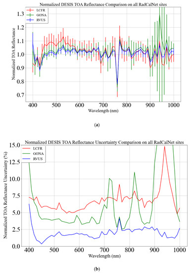
Figure 19.
Mean of normalized DESIS TOA reflectance using different sites (a) and its corresponding uncertainty (b). The blue, green, and red data represent RVUS, GONA, and LCFR data, respectively.
Variability of mean DESIS normalized TOA reflectance is the highest at LCFR, i.e., approximately 7%, as shown in Figure 19b. As LCFR is a sparsely vegetative site and thus highly sensitive to seasonal dynamics and BRDF effects, some level of extra variability is expected. This is the reason why vegetative sites are not considered as an ideal surface type for radiometric calibration and validation. Another reason for the observed extra variability is due to the DESIS acquisition time. The acquisition time of coincident datasets ranged from 9:00 AM to 3:00 PM. BRDF effect is highly pronounced in DESIS data acquired at 9:00 AM or at 3:00 PM due to higher solar zenith angles than those observed at noon. In addition, DESIS geolocation inaccuracy, which is approximately 1 pixel [2,34], resulted in higher variability at the LCFR due to smaller ROI size (4 pixels × 4 pixels).
Evaluating DESIS using RVUS shows the highest accuracy and precision (within 5% and 2.5%, respectively) as shown in Figure 19. Such a level of accuracy and precision is observed due to the homogenous nature of the site and minimum BRDF effect. Some of the observed discrepancies are due to BRDF effect as a result of different viewing and solar geometries. However, differences in solar zenith and azimuth angles for the comparison datasets is within 1° and 5°. Such small differences in solar geometry will likely have a minimal impact on the observed TOA reflectance discrepancies as shown in Figure 7b. In addition, DESIS view angle on RVUS is within 4° as shown in Figure 5. Previous studies have shown that BRDF effect on RVUS is minimal for viewing angles less than 10° [35]. Similarly, BRDF correction at RVUS is consistent within time and space to ~2% for view angles as large as 30° [36] which supports the assertion that BRDF effect on RVUS data for a view angle less than 4° is minimal. BRDF effect due to the two different view azimuth angles, 56° and 123°, corresponding to DESIS ascending and descending mode acquisitions, has minimal effects as the view angle of DESIS is within 4°. Therefore, the level of accuracy and precision at RVUS is achieved due to the nature of its surface type, i.e., playa. However, GONA, despite having a similar surface type, shows lower precision.
GONA shows an accuracy within 5% and precision within 4% as shown in Figure 19a,b, respectively. The observed precision is 1.5% higher than at RVUS as the normalized TOA reflectance on GONA has more variation than on RVUS as shown in Figure 7a and Figure 11a, respectively. Some of the observed variation, even though it is minimal, is due to the range of view zenith angles, i.e., 0.43° to 21° [37]. For such a large range of view zenith angles, it is very likely that BRDF effect was pronounced. However, 13 out of 15 acquisitions on GONA have a view zenith angle less than 10° resulting in minimum BRDF effect. DESIS has two view azimuth angles at GONA, i.e., 42° and 137°, corresponding to an ascending and a descending mode acquisition. In order to understand the effects that view azimuth angle has on the reflectance data, DESIS-normalized TOA reflectance data are divided into two datasets: one for ascending mode and the other for descending mode. Out of 15 coincident acquisitions, six spectra are from descending mode and nine spectra are from ascending mode as shown by the blue and magenta curves in Figure 20. Although some of the spectra from ascending mode acquisitions show higher deviation, there is not any clear evidence for higher discrepancies as a function of view azimuth angle.
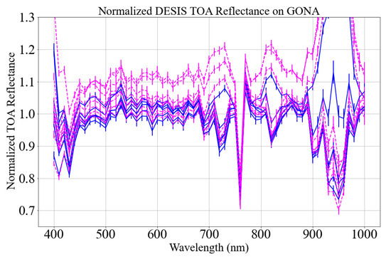
Figure 20.
Mean of normalized DESIS TOA reflectance on GONA. Blue and magenta curves represent spectra from descending and ascending mode acquisitions, respectively.
BRDF effect is inevitable in optical remote sensing sensors and pronounced to different degrees based on surface type. Angular effect on the surface types of RVUS (playa) and GONA (sand) has a minimal effect on the TOA reflectance whereas for the surface type of LCFR (pebble and sparse vegetation) there is a substantial effect on the TOA reflectance, which imposes a few challenges while using this site for radiometric evaluation of the sensor. BRDF characterization of these RadCalNet sites would help to further reduce the BRDF effect and improve sensor characterization.
This work showed that DESIS has radiometric accuracy and precision within 5% for most of the spectral channels. DESIS’s radiometric accuracy is similar to EO-1 Hyperion despite a 3% lower precision (Hyperion exhibits 5% accuracy and 2% precision) [5]. Availability of hyperspectral data of 5% absolute radiometric accuracy will benefit many different applications. Additionally, sensor calibration will also be benefited from a new source of hyperspectral data. A recently developed continental scale extended pseudo-invariant calibration sites (EPICS) calibration technique has limited usage due to lack of hyperspectral data [38,39]. DESIS data could be a huge addition to the hyperspectral characterization of EPICS. Validated hyperspectral data can also be used to address some of the critical challenges of sensor harmonization such as spectral band difference adjustment [9] and BRDF issues [40]. DESIS data can also be used synergistically with other hyperspectral missions as none of these missions are a global mapping mission. Generally, hyperspectral missions have lower spatial and temporal coverage [41] in comparison to multispectral missions such as Landsat [42] and Sentinel [43]. DESIS can be cross-calibrated with previous hyperspectral missions such as Earth Observing (EO)-1 Hyperion [41]; ongoing hyperspectral missions such as HySIS, PRISMA, and HISUI [7]; and upcoming hyperspectral missions such as CLARREO Pathfinder [8,44], and others [45,46] to create a continuous chain of hyperspectral imaging of Earth’s surface both in the spatial and temporal domain. The synergy between these missions will help the broader scientific community improve their current understanding and explore a wide range of new applications.
6. Conclusions
The radiometric quality of any optical satellite sensor is of great interest to the remote sensing community as it provides several opportunities for enhancing the current understanding of the Earth’s surface and atmosphere. Different multispectral and hyperspectral missions have been launched for providing a science grade image of the Earth surface from different orbits. Recently, DESIS was installed into MUSES on ISS for hyperspectral imaging of the Earth. As it is one of very few ongoing hyperspectral missions, its radiometric quality is of prime interest.
This work presents radiometric evaluation of DESIS data using the reflectance-based vicarious calibration approach. For this approach, RadCalNet sites were used as a reference, as they have been widely used for radiometric evaluation of various multispectral and hyperspectral missions. DESIS radiometric evaluation used 24 coincident acquisitions between DESIS and three RadCalNet sites: RVUS, GONA, and LCFR. DESIS shows an absolute radiometric accuracy and precision of 5% or greater for most of the spectral channels excluding the spectral regions affected by water vapor absorption and atmospheric aerosol scattering. DESIS radiometric accuracy observed from all the RadCalNet sites is similar for wavelengths longer than 580 nm; however, its accuracy is surface type dependent for the shorter wavelengths. RVUS and GONA shows similar accuracy of approximately 5% for wavelengths less than 550 nm whereas LCFR shows accuracy of ~10%. The increase in discrepancies at LCFR is due to the presence of sparse vegetation. Precision of radiometric accuracy is different for each of the three RadCalNet sites; RVUS, GONA, and LCFR show precision of 2.4%, 4%, and 7%, respectively.
Radiometric accuracy and precision within 5% and high spectral sampling of 2.55 nm will help users investigate narrow band features of different surface types. In addition, its off-nadir capacity along with MUSES pointing ability aids BRDF study of different surface types. These features make DESIS a unique sensor that offers greater data acquisition variety than existing hyperspectral missions in both spectral and angular domains. Along with numerous benefits, some of its most promising applications include addressing the spectral band difference between two different sensors and understanding and minimizing surface angular effects, both of which are very critical for sensor interoperability.
Author Contributions
Conceptualization, M.S.; methodology, M.S.; software, M.S.; formal analysis, M.S. and D.H.; investigation, M.S.; data curation, M.S.; writing—original draft preparation, M.S.; writing—review and editing, M.S., D.H. and J.C.; visualization, M.S., D.H..; supervision, D.H. and J.C.; project administration, J.C. All authors have read and agreed to the published version of the manuscript.
Funding
The work was performed by KBR contractor supporting the ECCOE under USGS contract number 140G0121D0001.
Institutional Review Board Statement
Not applicable.
Informed Consent Statement
Not applicable.
Data Availability Statement
RadCalNet data are available in a publicly accessible repository and can be found https://www.radcalnet.org/#!/ (accessed on 12 March 2021). Restrictions apply to the availability of DESIS data used for this research. Data was obtained under terms of the NASA commercial data purchase.
Acknowledgments
The authors would like to thank Kara Burch from I2R for helping us to develop preliminary understanding about DESIS data. Authors would also like to express their gratitude to Michelle While, Alexander Denevan, and Fatima Tuz Zafrin Tuli for their invaluable suggestions in the manuscript.
Conflicts of Interest
The authors declare no conflict of interest. Any use of trade, firm, or product name(s) is for descriptive purposes only and does not imply endorsement by the U.S. Government.
References
- Wu, Z.; Snyder, G.; Vadnais, C.; Arora, R.; Babcock, M.; Stensaas, G.; Doucette, P.; Newman, T. User needs for future Landsat missions. Remote Sens. Environ. 2019, 231, 111214. [Google Scholar] [CrossRef]
- Alonso, K.; Bachmann, M.; Burch, K.; Carmona, E.; Cerra, D.; de los Reyes, R.; Dietrich, D.; Heiden, U.; Hölderlin, A.; Ickes, J. Data Products, Quality and Validation of the DLR Earth Sensing Imaging Spectrometer (DESIS). Sensors 2019, 19, 4471. [Google Scholar] [CrossRef] [Green Version]
- Gao, B.-C.; Montes, M.J.; Davis, C.O.; Goetz, A.F. Atmospheric correction algorithms for hyperspectral remote sensing data of land and ocean. Remote Sens. Environ. 2009, 113, S17–S24. [Google Scholar] [CrossRef]
- Acosta, I.C.C.; Khodadadzadeh, M.; Tusa, L.; Ghamisi, P.; Gloaguen, R. A machine learning framework for drill-core mineral mapping using hyperspectral and high-resolution mineralogical data fusion. IEEE J. Sel. Top. Appl. Earth Obs. Remote Sens. 2019, 12, 4829–4842. [Google Scholar] [CrossRef]
- McCorkel, J.; Thome, K.; Ong, L. Vicarious calibration of EO-1 Hyperion. IEEE J. Sel. Top. Appl. Earth Obs. Remote Sens. 2012, 6, 400–407. [Google Scholar] [CrossRef] [Green Version]
- Pignatti, S.; Palombo, A.; Pascucci, S.; Romano, F.; Santini, F.; Simoniello, T.; Umberto, A.; Vincenzo, C.; Acito, N.; Diani, M. The PRISMA hyperspectral mission: Science activities and opportunities for agriculture and land monitoring. In Proceedings of the 2013 IEEE International Geoscience and Remote Sensing Symposium-IGARSS, Melbourne, VIC, Australia, 21–26 July2013; pp. 4558–4561. [Google Scholar]
- Iwasaki, A.; Ohgi, N.; Tanii, J.; Kawashima, T.; Inada, H. Hyperspectral Imager Suite (HISUI)-Japanese hyper-multi spectral radiometer. In Proceedings of the 2011 IEEE International Geoscience and Remote Sensing Symposium, Vancouver, BC, Canada, 24–29 July 2011; pp. 1025–1028. [Google Scholar]
- Shea, Y. Pathfinder Mission for Climate Absolute Radiance and Refractivity Observatory (CLARREO) Pathfinder. Available online: https://clarreo-pathfinder.larc.nasa.gov/clarreo/ (accessed on 7 December 2020).
- Chander, G.; Mishra, N.; Helder, D.L.; Aaron, D.B.; Angal, A.; Choi, T.; Xiong, X.; Doelling, D.R. Applications of spectral band adjustment factors (SBAF) for cross-calibration. IEEE Trans. Geosci. Remote Sens. 2012, 51, 1267–1281. [Google Scholar] [CrossRef]
- Pinto, C.T.; Shrestha, M.; Hasan, N.; Leigh, L.; Helder, D. SBAF for cross-calibration of Landsat-8 OLI and Sentinel-2 MSI over North African PICS. In Proceedings of the Earth Observing Systems XXIII, Event: SPIE Optical Engineering + Applications, San Diego, CA, USA, 7 September 2018; p. 107640Y. [Google Scholar]
- Dinguirard, M.; Slater, P.N. Calibration of space-multispectral imaging sensors: A review. Remote Sens. Environ. 1999, 68, 194–205. [Google Scholar] [CrossRef]
- Biggar, S.F.; Thome, K.J.; Wisniewski, W. Vicarious radiometric calibration of EO-1 sensors by reference to high-reflectance ground targets. IEEE Trans. Geosci. Remote Sens. 2003, 41, 1174–1179. [Google Scholar] [CrossRef] [Green Version]
- Barsi, J.A.; Alhammoud, B.; Czapla-Myers, J.; Gascon, F.; Haque, M.O.; Kaewmanee, M.; Leigh, L.; Markham, B.L. Sentinel-2A MSI and Landsat-8 OLI radiometric cross comparison over desert sites. Eur. J. Remote Sens. 2018, 51, 822–837. [Google Scholar] [CrossRef]
- Bouvet, M.; Thome, K.; Berthelot, B.; Bialek, A.; Czapla-Myers, J.; Fox, N.P.; Goryl, P.; Henry, P.; Ma, L.; Marcq, S. RadCalNet: A Radiometric Calibration Network for Earth Observing Imagers Operating in the Visible to Shortwave Infrared Spectral Range. Remote Sens. 2019, 11, 2401. [Google Scholar] [CrossRef] [Green Version]
- Sebastian, I.; Krutz, D.; Eckardt, A.; Venus, H.; Walter, I.; Günther, B.; Neidhardt, M.; Reulke, R.; Müller, R.; Uhlig, M. On-ground calibration of DESIS: DLR’s Earth Sensing Imaging Spectrometer for the International Space Station (ISS). In Proceedings of the Optical Sensing and Detection V, Event: SPIE Photonics Europe, Strasbourg, France, 9 May 2018; p. 1068002. [Google Scholar]
- Krutz, D.; Müller, R.; Knodt, U.; Günther, B.; Walter, I.; Sebastian, I.; Säuberlich, T.; Reulke, R.; Carmona, E.; Eckardt, A. The instrument design of the DLR earth sensing imaging spectrometer (DESIS). Sensors 2019, 19, 1622. [Google Scholar] [CrossRef] [PubMed] [Green Version]
- Thome, K.J.; Helder, D.L.; Aaron, D.; Dewald, J.D. Landsat-5 TM and Landsat-7 ETM+ absolute radiometric calibration using the reflectance-based method. IEEE Trans. Geosci. Remote Sens. 2004, 42, 2777–2785. [Google Scholar] [CrossRef]
- Thome, K.; Nandy, P. Accuracy of ground-reference calibration of imaging spectroradiometers at large sensor view angles. J. Remote Sens. Soc. Jpn. 2000, 20, 602–614. [Google Scholar]
- Thome, K.; Cattrall, C.; D’Amico, J.; Geis, J. Ground-reference calibration results for Landsat-7 ETM+. In Proceedings of the Earth Observing Systems X, Event: Optics and Photonics, San Diego, CA, USA, 22 August 2005; p. 58820B. [Google Scholar]
- Czapla-Myers, J. RadCalNet Site Description. CEOS Reference: QA4EO-WGCV-IVO-CSP-002_RVUS; University of Arizona: Tucson, AZ, USA, 2018. [Google Scholar]
- Santer, R.; Gu, X.; Guyot, G.; Deuze, J.; Devaux, C.; Vermote, E.; Verbrugghe, M. SPOT calibration at the La Crau test site (France). Remote Sens. Environ. 1992, 41, 227–237. [Google Scholar] [CrossRef]
- Meygret, A. RadCalNet Site Description.CEOS Reference: QA4EO-WGCV-IVO-CSP-002_LCFR; CNES, Physics for Optical Mesurement Service: Belin, France, 2018. [Google Scholar]
- Meygret, A.; Santer, R.P.; Berthelot, B. ROSAS: A robotic station for atmosphere and surface characterization dedicated to on-orbit calibration. In Proceedings of the Earth Observing Systems XVI, Event: SPIE Optical Engineering + Applications, San Diego, CA, USA, 13 September 2011; p. 815311. [Google Scholar]
- Ma, L. RadCalNet Site Description.CEOS Reference: QA4EO-WGCV-RadCalNet-BSCN-Q-v1; Academy of Opto-Electronics, Chinese Academy of Science: Beijing, China, 2018. [Google Scholar]
- Ma, L.; Zhao, Y.; Woolliams, E.R.; Dai, C.; Wang, N.; Liu, Y.; Li, L.; Wang, X.; Gao, C.; Li, C. Uncertainty Analysis for RadCalNet Instrumented Test Sites Using the Baotou Sites BTCN and BSCN as Examples. Remote Sens. 2020, 12, 1696. [Google Scholar] [CrossRef]
- Li, C.; Ma, L.; Gao, C.; Tang, L.; Wang, N.; Liu, Y.; Zhao, Y.; Dou, S.; Zhang, D.; Li, X. Permanent target for optical payload performance and data quality assessment: Spectral characterization and a case study for calibration. J. Appl. Remote Sens. 2015, 8, 083498. [Google Scholar] [CrossRef]
- Greenwell, C. RadCalNet Site Description. CEOS Reference: QA4EO-WGCV-IVO-CSP-002_GONA; National Physical Laboratory: Hampton Raod, UK, 2018. [Google Scholar]
- Thome, K. Sampling and uncertainty issues in trending reflectance-based vicarious calibration results. In Proceedings of the Earth Observing Systems X, Event: Optics and Photonics, San Diego, CA, USA, 22 August 2005; p. 588216. [Google Scholar]
- Jing, X.; Leigh, L.; Teixeira Pinto, C.; Helder, D. Evaluation of RadCalNet Output Data Using Landsat 7, Landsat 8, Sentinel 2A, and Sentinel 2B Sensors. Remote Sens. 2019, 11, 541. [Google Scholar] [CrossRef] [Green Version]
- Pratlong, J.; Burt, D.; Jerram, P.; Mayer, F.; Walker, A.; Simpson, R.; Johnson, S.; Hubbard, W. CMOS sensors for atmospheric imaging. In Proceedings of the International Conference on Space Optics—ICSO 2016, Biarritz, France, 18–21 October 2016; p. 105622N. [Google Scholar]
- Shrestha, M.; Christopherson, J. Cross Comparison of DESIS with Landsat 8 OLI and Sentinel 2A MSI. In Proceedings of the Calcon, Space Dynamics Laboratory, Logan, UT, USA, 24 September 2020. [Google Scholar]
- Teixeira Pinto, C.; Jing, X.; Leigh, L. Evaluation Analysis of Landsat Level-1 and Level-2 Data Products Using In Situ Measurements. Remote Sens. 2020, 12, 2597. [Google Scholar] [CrossRef]
- Sterckx, S.; Wolters, E. Radiometric Top-of-Atmosphere Reflectance Consistency Assessment for Landsat 8/OLI, Sentinel-2/MSI, PROBA-V, and DEIMOS-1 over Libya-4 and RadCalNet Calibration Sites. Remote Sens. 2019, 11, 2253. [Google Scholar] [CrossRef] [Green Version]
- Aparajithan, S. USGS System Characterization Results and Plans. In Proceedings of the 19th JACIE Virtual Conference, USGS EROS, Sioux Falls, SD, USA, 18 November 2020. [Google Scholar]
- Czapla-Myers, J.S.; Coburn, C.A.; Thome, K.J.; Wenny, B.N.; Anderson, N.J. Directional reflectance studies in support of the Radiometric Calibration Test Site (RadCaTS) at Railroad Valley. In Proceedings of the Earth Observing Systems XXIII, Event: SPIE Optical Engineering + Applications, San Diego, CA, USA, 7 September 2018; p. 107640Z. [Google Scholar]
- Bruegge, C.J.; Coburn, C.; Elmes, A.; Helmlinger, M.C.; Kataoka, F.; Kuester, M.; Kuze, A.; Ochoa, T.; Schaaf, C.; Shiomi, K. Bi-Directional Reflectance Factor Determination of the Railroad Valley Playa. Remote Sens. 2019, 11, 2601. [Google Scholar] [CrossRef] [Green Version]
- Shrestha, M. Bidirectional Distribution Reflectance Function of Algodones Dunes. Master’s Thesis, South Dakota State University, Brookings, SD, USA, 2016. Available online: https://openprairie.sdstate.edu/etd/1141/ (accessed on 25 April 2021).
- Shrestha, M.; Hasan, N.; Leigh, L.; Helder, D. Derivation of Hyperspectral Profile of Extended Pseudo Invariant Calibration Sites (EPICS) for Use in Sensor Calibration. Remote Sens. 2019, 11, 2279. [Google Scholar] [CrossRef] [Green Version]
- Shrestha, M.; Leigh, L.; Helder, D. Classification of North Africa for Use as an Extended Pseudo Invariant Calibration Sites (EPICS) for Radiometric Calibration and Stability Monitoring of Optical Satellite Sensors. Remote Sens. 2019, 11, 875. [Google Scholar] [CrossRef] [Green Version]
- Claverie, M.; Ju, J.; Masek, J.G.; Dungan, J.L.; Vermote, E.F.; Roger, J.-C.; Skakun, S.V.; Justice, C. The Harmonized Landsat and Sentinel-2 surface reflectance data set. Remote Sens. Environ. 2018, 219, 145–161. [Google Scholar] [CrossRef]
- Pearlman, J.; Carman, S.; Segal, C.; Jarecke, P.; Clancy, P.; Browne, W. Overview of the Hyperion imaging spectrometer for the NASA EO-1 mission. In Proceedings of the IGARSS 2001. Scanning the Present and Resolving the Future. Proceedings. IEEE 2001 International Geoscience and Remote Sensing Symposium (Cat. No.01CH37217), Sydney, NSW, Australia, 9–13 July 2001; pp. 3036–3038. [Google Scholar]
- Loveland, T.R.; Dwyer, J.L. Landsat: Building a strong future. Remote Sens. Environ. 2012, 122, 22–29. [Google Scholar] [CrossRef]
- Drusch, M.; Del Bello, U.; Carlier, S.; Colin, O.; Fernandez, V.; Gascon, F.; Hoersch, B.; Isola, C.; Laberinti, P.; Martimort, P. Sentinel-2: ESA’s optical high-resolution mission for GMES operational services. Remote Sens. Environ. 2012, 120, 25–36. [Google Scholar] [CrossRef]
- Goldin, D.; Xiong, X.; Shea, Y.; Lukashin, C. CLARREO Pathfinder/VIIRS Intercalibration: Quantifying the Polarization Effects on Reflectance and the Intercalibration Uncertainty. Remote Sens. 2019, 11, 1914. [Google Scholar] [CrossRef] [Green Version]
- Transon, J.; d’Andrimont, R.; Maugnard, A.; Defourny, P. Survey of hyperspectral earth observation applications from space in the sentinel-2 context. Remote Sens. 2018, 10, 157. [Google Scholar] [CrossRef] [Green Version]
- Rast, M.; Painter, T.H. Earth Observation imaging spectroscopy for terrestrial systems: An overview of its history, techniques, and applications of its missions. Surv. Geophys. 2019, 40, 303–331. [Google Scholar] [CrossRef]
Publisher’s Note: MDPI stays neutral with regard to jurisdictional claims in published maps and institutional affiliations. |
© 2021 by the authors. Licensee MDPI, Basel, Switzerland. This article is an open access article distributed under the terms and conditions of the Creative Commons Attribution (CC BY) license (https://creativecommons.org/licenses/by/4.0/).