Abstract
Coarse registration of 3D point clouds plays an indispensable role for parametric, semantically rich, and realistic digital twin buildings (DTBs) in the practice of GIScience, manufacturing, robotics, architecture, engineering, and construction. However, the existing methods have prominently been challenged by (i) the high cost of data collection for numerous existing buildings and (ii) the computational complexity from self-similar layout patterns. This paper studies the registration of two low-cost data sets, i.e., colorful 3D point clouds captured by smartphones and 2D CAD drawings, for resolving the first challenge. We propose a novel method named ‘Registration based on Architectural Reflection Detection’ (RegARD) for transforming the self-symmetries in the second challenge from a barrier of coarse registration to a facilitator. First, RegARD detects the innate architectural reflection symmetries to constrain the rotations and reduce degrees of freedom. Then, a nonlinear optimization formulation together with advanced optimization algorithms can overcome the second challenge. As a result, high-quality coarse registration and subsequent low-cost DTBs can be created with semantic components and realistic appearances. Experiments showed that the proposed method outperformed existing methods considerably in both effectiveness and efficiency, i.e., 49.88% less error and 73.13% less time, on average. The RegARD presented in this paper first contributes to coarse registration theories and exploitation of symmetries and textures in 3D point clouds and 2D CAD drawings. For practitioners in the industries, RegARD offers a new automatic solution to utilize ubiquitous smartphone sensors for massive low-cost DTBs.
1. Introduction
Digital twin building (DTBs), as real-time ‘as-is’ 3D building models, have attracted great attention of both industry and academy due to the promised applications in the GIScience [1], manufacturing, robotics, mapping, architecture, engineering, construction, and operation (AECO) industries [2,3,4,5], and heritage documentation [6,7]. A DTB is a virtual representation of a physical building “across its lifecycle, using real-time data to enable understanding, learning, and reasoning” [8,9]. Three long-standing requirements on the roadmap of DTB, i.e., parametric geometry, rich semantics, and realistic appearances, are thus indispensable for fulfilling the functions of “understanding, learning, and reasoning” [10,11,12,13]. For example, in the design and operation phases, digital models with parametric geometry, rich semantics, and realistic appearances bring practitioners a more comprehensive and thorough understanding of the built environment, as well as solid data support for automation and analytics [4,8].
Researchers have developed a profusion of automated 3D building reconstruction methods, involving various expensive equipment such as Terrestrial Laser Scanner (TLS) and Mobile Light Detection and Ranging (LIDAR) System (MLS). Many existing methods can be used for DTBs; however, the methods are challenged in practices by (i) the high cost of labor, equipment, and time in data collection for numerous existing buildings [14] and (ii) the computational complexity from self-similar layout patterns [15]. In recent years, there has been fast and continuing progress in embedding the 3D scanning technologies in consumer-level mobile devices, such as smartphones and pads. Example projects and products include Android ARCore, Tango, and Apple AR Kit [16,17]. Unlike the solutions relying on costly TLS or MLS, new 3D scanning devices were increasingly affordable in daily practices. However, the 3D data collected by the consumer-level devices often has a quality problem, e.g., noisier or sparser than those produced by professional TLS or MLS equipment. Fortunately, many applications still benefited from the affordable 3D data by compensating noises with third-party data sources, such as pedestrian networks [18] and floor plans. Floor plan is an available data source in many cities, which have long-standing routines to collect the construction and renovation drawings. The building drawings can also be requested online at low prices, such as in Hong Kong’s BRAVO (Building Records Access and Viewing On-line, at HK$42 per sheet) system and New York City’s floor plan services (at US$5 per page). The public accessibility and affordable prices of floor plans make it a reliable source for DTBs.
This paper focuses on compensating the low-cost point clouds captured by ubiquitous smartphones with low-cost and widely available 2D computer-aided design (CAD) drawings for DTBs. Figure 1 summarizes how the two inexpensive data sets can complement each other. The main idea is that the scanning defects, including sparsity, noises, occlusions, and distortions, can be reduced by the as-designed CAD drawings [19]. In turn, smartphones’ colorful 3D point clouds can add the actual situations and realistic appearances to the CAD drawings. Coarse registration, thus, is indispensable to transform the 3D point cloud under the same spatial reference as the drawing, to integrate the as-built and as-designed datasets [15].
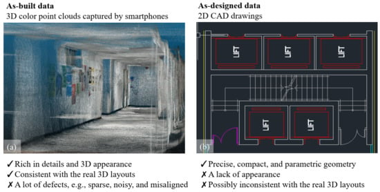
Figure 1.
Comparison of two inexpensive data sets for DTBs. (a) Smartphone’s colorful 3D point clouds; (b) 2D CAD drawings.
The coarse registration problem is typically solved by finding the optimal transformation, i.e., rotation, translation, and scaling, which is often with high degrees of freedom (DoFs). Many existing coarse registration methods thus rely on unique local features-based initial alignments close to the global minimum to escape from the local optima in such high-DoFs problems [20]. However, the self-similar layout patterns in building interiors make it problematic for the conventional method to find promising initial alignments [15,21]. In summary, the high-level DoFs and self-similarities of indoor layouts challenge the local feature-based ‘shortcuts’ in conventional registration methods.
Inspired by symmetric cross-sections as robust global–rather than local–features [5], we propose a novel coarse registration method, named Registration based on Architectural Reflection Detection (RegARD), that transforms the self-symmetries in the challenge from a barrier to a facilitator. The RegARD first detects the symmetry axes in point clouds and CAD drawings to reduce the DoFs by constraining the rotation in parallel or perpendicular to the axes. Then, RegARD employs advanced nonlinear optimization algorithms, such as CMAES [22], DIRECT [23], and Nelder-Mead [24], to obtain the optimum registration. In other words, RegARD segments the high-DoF optimization of rotation, translation, and scaling into a lower-DoF subproblem on rotation and another lower-DoF subproblem on translation and scaling. As a result, both the efficiency and accuracy of coarse registration can be improved notably. Based on RegARD’s results, DTBs can be generated in the Industry Foundation Classes (IFC) format automatically with realistic textures mapped from point clouds. Overall, RegARD can facilitate the creation of DTBs in several aspects: parametric geometry, rich semantics, and realistic appearances, and processing time.
The remainder of this paper is organized as follows. Section 2 summarizes the point cloud registration methods and the point cloud processing with architectural regularities. Section 3 presents the details of RegARD. Section 4 reports the experimental registration results of our large-scale dataset of seven stories and present the generated IFC models as resulted DTB. We then discuss our digital twinning solution and RegARD method in Section 5 and conclude the study in Section 6.
2. Literature Review
2.1. Point Cloud Registration
Pairwise point set registration is a fundamental yet challenging task in geometry processing and digital twinning. The registration problem is often decomposed into two sub-problems: (1) feature detection and (2) correspondence and transformation estimation. In the literature, many related studies focusing on the second sub-problem are termed as ‘fine’ registration. A fine registration assumes high-quality initial correspondences with correct and accurate features. Thus, the main task of fine registration is improving the initial transformation in a close form with given correspondences. However, the optimal correspondences are finally determined by the optimal transformation—there exists a ‘chicken-egg’ dilemma between determining high-quality correspondences and optimal transformation. Therefore, ‘coarse’ registration emerged for resolving the dilemma by solving both sub-problems.
For resolving the first sub-problem of coarse registration, hand-crafted features with explicit meanings of point sets were proposed first to detect and describe key points for correspondences establishment. Examples of explicit features are Spin Image [25], Point Signature [26], and FPFH [27]. However, it is extremely difficult and burdensome to craft robust and comprehensive local features for the wide diversity and deficiency of points [28]. Recently, implicit features have been exploited for registration extensively using deep neural networks [28,29,30,31]. For example, FCGF integrates a fully convolutional network, 3D sparse representation, and contrastive loss, and achieved higher feature detection compared to hand-crafted counterparts [29].
For resolving the second sub-problem, the Iterative Closest Point (ICP) [32,33] is a classical mechanism. Yet, ICP can be easily stuck by local minima without high-quality initial alignments [34]. Variants of ICP were thus proposed for escaping from the local minim; examples are CPD [35], Go-ICP [36], and GMMTree [37]. Besides, researchers also formulated the whole registration problem into end-to-end formulations, e.g., supervised learning pipelines and nonlinear mathematical programming [38]. Representative studies include the deep learning versions of ICP, of which one is coined as Deep Iterative Point [39] and another is Deep Global Registration [40].
However, the coarse registration of the point sets is not fully addressed for DTB, especially in the complex and repetitive indoor settings. There are two possible reasons for the limited effectiveness. First, the common self-similarity in multiple scales of building interiors hinders traditional feature detection [15]. Secondly, building interiors’ 2D and 3D manifolds without complex inner structures also lead to and creates massive local optima “traps” for correspondences and transformation optimization.
2.2. Point Cloud Processing with Architectural Regularities
Researchers in remote sensing, construction, and computer vision have utilized architectural regularities in processing point clouds for modeling 3D buildings. For example, the vertical and horizontal planes in urban and indoor spaces can be useful a priori primitives for registration and reconstruction. Xu et al. [41] and Bueno et al. [15] introduced a feature descriptor, i.e., four-plane congruent set (4PNCS), for urban and building scenarios, respectively; 4PNCS significantly reduced the number of correspondences and improved the matching efficiency. Similarly, plane sets representing the main structures of the built environment are also applied in determining the structure-level correspondences robustly and efficiently [42]. Besides, Zolanvari et al. [43] proposed an improved slicking model (ISM) to segment facades based on some geometric characteristics of planes. Polewski and Yao [44] used the intersections of adjacent planar surfaces as line correspondences and the roof symmetry axes to co-register multimodal data such as LIDAR point clouds and digital surface models. Chen et al. [45] regularized rooftop elements from LIDAR points onto 2.5D block-building models and validated them in a high-density high-rise area.
Moreover, repetition and similarity are also prevalent in heuristic rules for urban and building reconstruction. For example, Wang et al. [46] incorporated the local symmetries into a nonlinear least-squares optimization for reconstructing the contours of building roofs. Ceylan et al. [47] recognized the windows on facades by the repetitions in photogrammetric point clouds. Cheng et al. [48] applied rotational symmetry and slicing to register buildings such as towers. Although the idea is very inspiring and similar to RegARD, the targeted data of [48] is building exteriors with rotational symmetry, while ours are building interiors with reflection symmetry and different self-similarities. For detecting the reflection symmetry, Xue et al. [49] integrated state-of-the-art derivative-free optimization (DFO) algorithms from applied mathematics and computer science for detecting the architectural reflection effectively and efficiently. Xue et al. [5,50] demonstrated that the reflection detection of points successfully improved indoor DTB and cross-section features for clustering unknown objects in LIDAR clouds for a digital twin city. Therefore, it will be intriguing to apply the architectural reflection symmetry to the challenging registration problem of large-scale as-built 3D scans with as-designed 2D drawings.
2.3. Digital Twinning of Building Interiors
LIDAR and photogrammetric point clouds have been widely used for digital twins of building interiors. Three groups of interior components received the most attention: (i) the physical building components and structures, e.g., walls and slabs, (ii) indoor spaces and partitions, e.g., stories and rooms, and (iii) indoor topology. For the physical components, plane detection and curved surface segmentation usually precede the digital twinning for candidate surfaces [51,52,53]. For the volumes, Bassier and Vergauwen [51] estimated walls’ axes in different shapes; Nikoohemat et al. [53] designed heuristic rules to label plane segments based on the adjacency graph; Ochmann et al. [54] processed point clouds into 3D cell complexes and labeled them, as rooms and structures, using integer programming; Wang et al. [52] generated a semantic wireframe of permanent structures based on the boundaries of classified planes. For spaces and partitions, stores are usually extracted by z-coordinates clustering of the whole point clouds or classified planes [51,55]. Moreover, Ochmann et al. [54] cast rays onto the wall surfaces from unoccupied locations for detecting wall loops and rooms; Murali et al. [56] detected room cuboids from a wall graph; Jung et al. [55] projected a story’s point clouds to a 2D plane and segmented the rooms’ footprints. For indoor topology, Bassier and Vergauwen [51] reconstructed four types of connections by heuristic rules; Wang et al. [52] regularized the geometry of planar boundaries and repaired incorrect connections by a conditional Generative Adversarial Network.
Apart from the DTBs using high-cost LIDAR systems, floor plans can serve as an affordable data source to an alternative solution. For example, vectorized floor plans contain semantic as-designed indoor layouts, which can be extracted via computer vision and optimization methods [57,58]. The as-designed indoor layouts can facilitate processing scanned point clouds. Wijmans and Furukawa [59] presented a Markov Random Field inference formulation for the scan placements problem over a given floor plan image; the formulation can guide the registration of multiple indoor scan fragments with as-designed data. In summary, it is promising to triangulate the mainstream as-built point clouds with as-designed floor plans in terms of reducing costs and improving the correctness and accuracy of the digital twinning procedures.
3. Methodology
3.1. Overview
Figure 2 shows a flowchart of our automatic DTB creation pipeline. The inputs included a point cloud captured by a smartphone and the corresponding 2D CAD drawing of the floor plan. This pipeline output the registered point clouds with the 3D semantic models generated from CAD drawings. Finally, we could create DTB with textures mapped from the registered point clouds.
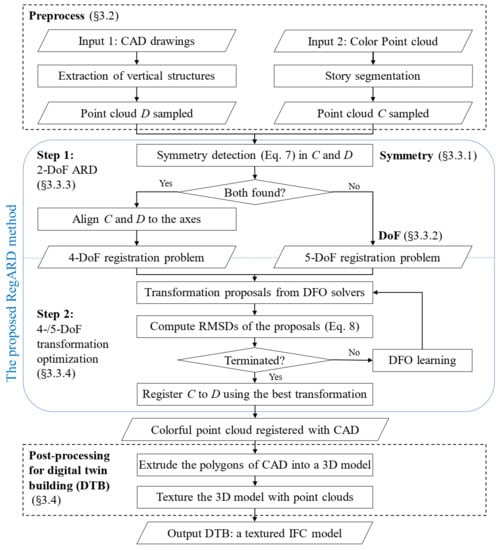
Figure 2.
Flowchart of the proposed RegARD method for DTB.
From the inputs to the outputs, there were two processing stages. The first stage (Section 3.2) of this pipeline was the preprocessing of the inputs: separating the point clouds into stories, extracting the semantic and vertical structures from CAD drawings with a method named Plan2Polygon, and finally sampling the 2D points from the processed point clouds and CAD drawings of each story respectively. The second stage (Section 3.3) was the crucial registration, i.e., RegARD. The point cloud of each story here was the source geometry, while its paired CAD drawing was the target geometry. The registration transformed the source to match the target geometry. The first step of RegARD was the Architectural Reflection Detection (ARD) part. The reflection symmetry axes of sampled 2D points from the point clouds and CAD drawings were detected. Next, an initial transformation was applied to align the symmetry axes of the paired point cloud and CAD drawing of the same story. By doing so, RegARD constrained the rotation in a set of four values down from , to reduce one DoF due to , where denotes the result of ARD and indicates set cardinality. Next, RegARD solves the remaining four DoFs, i.e., translation and scaling along the x and y axes, by DFO algorithms and outputs the final transformation parameters to register the story point cloud with its corresponding CAD drawing. Besides, we also briefly introduce the process to generated textured DTB (Section 3.4) after the registration.
3.2. Preprocessing
This stage extracted and sampled the vertical structures from CAD drawings for the coarse registration. The structure polygons and openings were parsed out from the drawings, while stories were separated from the original point clouds. Finally, both the vertical structures from drawings and point clouds were sampled with a range of proper densities for registration. Note that the 3D scanning and the 2D CAD drawings were sampled into 2D points to reduce the computational cost.
3.2.1. Parsing Cad Drawings (Plan2polygon)
The preprocessing employed a new in-house developed schema, called Plan2Polygon, for parsing CAD drawings: using polygon-based rules to extract vertical structures, i.e., walls, pillars, and windows. A preliminary pipeline of the preprocessing schema consisted of the following three parts: (i) CAD filtering, (ii) structure polygonization, and (iii) openings simplification.
First, unnecessary elements and semantics were removed from CAD drawings (Figure 3a). Annotations of names, dimensions, and furniture, isolated doors, and other unnecessary elements could be quickly filtered out using CAD software.
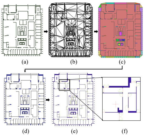
Figure 3.
Polygonization of 2D story plan based on CAD drawings. (a) Filtered segments of vertical structures; (b) triangles by constraint triangularization; (c) merged polygons; (d) filtered and filled polygons of structures; (e) simplified door symbols connecting walls; (f) details of simplified doors, where the green lines are the original symbols and the red ones are simplified results.
Then, the building interior was polygonized based on the structure lines. We first triangulated the planes with the structure lines as constraint segments (Figure 3b). These triangles were merged into polygons by a region-growing process [60]: pick one triangle as a seed and expand its neighborhood triangles until meeting the structure lines (Figure 3c). Next, the polygons could be further classified into objects, such as walls, windows, and staircases. This study focused on the vertical structures, especially walls, for the following texturing process. Therefore, the approach extracted these ‘thin’ vertical structures by a thickness index:
is the area function of a given polygon g whose external boundary is constructed by an ordered list of n points . Note that g may contain holes, i.e., internal boundaries that are also constructed by ordered lists of points. is a buffer function which offsets the boundary (or boundaries) of a given polygon g to its interior by a distance of t. Polygons processed here are assumed to be not self-intersected. The longer and narrower the polygon is, the smaller the is. Therefore, we could extract the polygons with an less than a given threshold as vertical structures (Figure 3d). The values of t and the threshold of in our experiments will be introduced in Section 4.2. This filter was simple yet effective to extract the vertical structures of our test data with very few square wall parts nor columns. Furthermore, one could easily extend the Plan2Polygon with more advanced classifiers to recognize square wall parts and columns.
Openings, such as doors in this study, were always drawn as curves and/or multiple segments in CAD drawings. We simplified them into 2D segments for creating their 3D blocks in the following stages. This simplification was adopted from [58]. Convex hulls were generated for each door symbol and intersect with its adjacent vertical structure polygons. The shortest path connecting two intersections was the final simplified segment for each door symbol (Figure 3).
3.2.2. Segmentation of Point Clouds by Stories
The preprocessing also extracted each story in the as-built point cloud P, using a similar process as [61]. We first calculated the distribution histogram of the heights, i.e., the z-components of all points in P, as shown in Figure 4. We set the bin interval of the histogram as 0.3 m according to our experiments. Next, the peaks of the histogram were detected as floors and ceilings. To remove some noisy peaks caused by facilities or staircases, we also set two height-difference thresholds of continuous peaks, i.e., the wall height of a story and the height between a ceiling and the floor of the upper story. Consequently, the filtered peaks were in a repeated ‘floor-ceiling’ pattern. Note that this process was based on the assumption that the z-components of points only concentrated on the floors and ceilings, which would be problematic when there were stepped floors and other large z-components clusters in the middle of the stories. However, this assumption holds in many standard buildings, including the test data in this study.

Figure 4.
Separation of stories in the point cloud, where the green dots are the detected floor and ceiling heights, and the red crosses are the peaks filtered out.
3.2.3. Sampling 2D Points
Finally, we sampled points from the footprints of the parsed structures of CAD drawings and the story-separated point clouds. To sample CAD structures, we extracted points along the boundaries of structure polygons or opening lines. To sample point clouds, we removed the floors and ceilings of the story-separated point clouds, projected the middle part of a story onto a 2D horizontal plane, then randomly sampled the projected points.
3.3. The Proposed Regard Method
The pseudo-codes of the proposed RegARD are described in Figure 2. The RegARD solved the coarse registration in two manageable steps. The first step of RegARD was the architectural reflection detection (ARD) of both the source and destination point clouds, e.g., C and D, as shown in Figure 2. If both symmetry axes were found, C and D were aligned to the axes to constrain the searching space of the transformation as a four-DoF problem. Otherwise, the RegARD received the coarse registration as a five-DoF problem, which had an extra DoF of the relative rotation. The second step of RegARD optimized the transformation iteratively for the four-/five-DoF problem.
3.3.1. Symmetry as a Global Feature
Registering point clouds to CAD drawings was challenging due to the omnipresent self-similarity of building interiors and computation complexity to solve the transformation. Figure 5 shows an example of the Root-Mean-Square Distance (RMSD) curve of registration with different rotations, while the translation and scaling DoFs were ‘frozen’ at the fittest value.
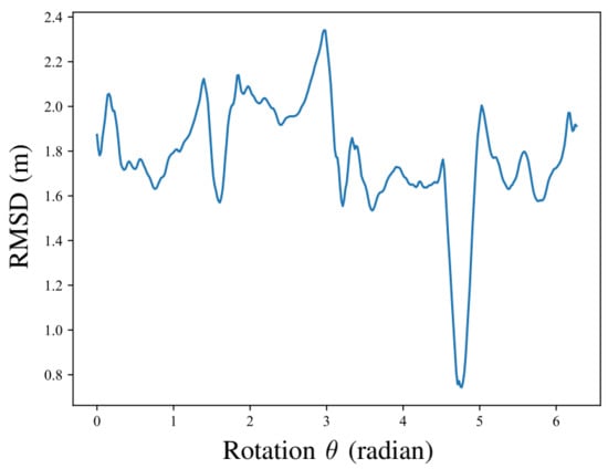
Figure 5.
Example registration RMSD curve against the rotation.
The curve was also ‘rugged.’ In other words, many local minima of rotations could trap the conventional methods. However, the rugged RMSD curve in Figure 5 also inspired in us the idea of using the architectural reflection symmetry as a global feature. That is, the minimal RMSD was associated with the optimum rotation that moves the reflection symmetry axes of the source point cloud to the destination. Therefore, RegARD detected the reflection symmetry axes of both the source and target geometry. By doing so, the fittest rotation could be almost solved, and there are only four DoFs left for the optimization to solve, which significantly eased the registration optimization.
3.3.2. DoFs in Regard
Different types of symmetry have different parameterization [49,62]. This study focuses on the detection of reflection symmetry, one of the most fundamental layout patterns in architecture for aesthetic and practical reasons. For a point cloud C, the reflection symmetry axis s can be parameterized by , , , as shown in Figure 2, where is the distance from the origin to the symmetry axis, is the angle from the positive x-axis direction to the line perpendicular to s through O. The polar function of s can be writen as , where is the polar coordinates of points on s. The polar coordinate can also be converted into a Cartesian coordinate as . Based on this parameterization, the reflection symmetry transformation applied on a 2D point is parameterized as:
and p here are the 3D homogeneous coordinates, i.e., and respectively, of their 2D counterparts.
To register the sampled point cloud to the 2D CAD drawing, the transformation has five DoFs, i.e., the rotation angle , 2D scaling factors s, and 2D translation offsets t, applied on a 2D point is parameterized as:
Similar to Equation (2), and p are 3D homogeneous coordinates in . We used individual scaling factors for x-y axes because different drifting rates along the different axes of 3D scanning by SLAM causeddifferent scaling factors along x-y axes of the registration. Yet, if the rotation was constrained as one (or four) constant, became a four-DoF problem.
3.3.3. Step 1: Two-DoF Architectural Reflection Detection
Formally, a subset S of n-dimensional Euclidean space is called symmetric with respect to a transformation T, if [62]. Moreover, since the symmetry of a building may not be rigorous in every detail, the transformation T can be determined by approximate descriptors. For example, to determine the symmetry transformation T from a point cloud, we can maximize the point correspondence rate (PCR) and RMSD, which are defined as follows [49,63]:
where is a cloud of n points; denotes the nearest point of p; is the Euclidean distance between two points and ; is the distance of p to C after transformation T; is a default distance threshold of correspondence [49]; and is the cardinality, i.e., the number of points, of C. Both PCR and RMSD measure the degree of shape preservation after transformation T. The difference is that PCR counts the preserved points and RMSD indicates the distance errors.
In this study, we defined the symmetry detection function as in the ODAS [49] to:
The problem to optimize in Equaiton (7) had two DoFs. The ARD determined the reflection symmetry axis of a point cloud C, the reflection transformation based on this axis should maximize the PCR and minimize the RMSD as defined in Section 3.3.3. Therefore, the ODAS minimized the following objective, i.e., Equation (7), to solve and . Note that the RMSD was subdivided by the diagonal length of C, denoted as , to avoid the scale impact of the point cloud.
3.3.4. Step 2: Four-DoF Transformation Optimization
The optimization problem of the coarse registration was thus simplified to:
where is the source geometry after the alignment of the reflection axes. , where . Moreover, and are bounded in . It is clear that Equation (8) is equivalent to a four-DoF problem.
Note that the registration of RegARD in Equation (8) is a partial-to-full matching. Therefore, most points in can find their correspondences in D and the correspondences are the nearest points when the transformation is close to the global minimum. Thus, it is not necessary to build a correspondence set filtered out non-overlapping geometry in this study. The RegARD employs a long list of up-to-date DFO solvers for computing the optimum transformation in Equation (8) iteratively. Notably, the algorithms benchmarked in this study included CMAES [22], DIRECT [23], MLSL, MMA, COBYLA, Nelder–Mead [24], SBPLX [64], AUGLAG, and BOBYQA.
3.4. Texturing for Digital Twin Buildings
After the registration, a post-processing cropped the point cloud and creates texture images for every major building element in the CAD, to form the final textured DTB. The workflow is presented in Figure 6. The parsed 2D footprint polygons of the indoor structures were vertically extruded into 3D blocks. The extrusion length was the height of the corresponding story point cloud. Moreover, the blocks were organized in boundary representation schema, so that the faces of blocks could be textured separately.
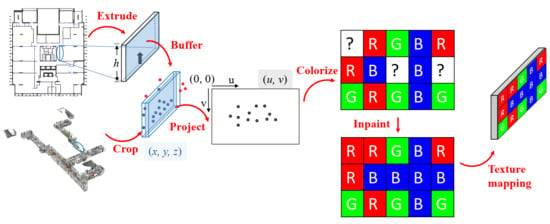
Figure 6.
Generating and texturing DTB from the point clouds and CAD drawings.
To texture a face, we buffered it into a rectangle along the face normal in both the positive and negative directions, called face box here. This box was used to crop the corresponding 3D region in the registered point cloud. However, repeatedly cropping thousands of relatively small boxes from the whole point cloud with almost 10 million points was very time-consuming. Therefore, to accelerate the cropping speed, the point cloud was first cropped into caching slices that covered the coplanar faces or parallel faces with small distances to each other. Next, the corresponding 3D point cloud region of a face was cropped by the face box from its corresponding caching slice. These caching slices shrank the extent of the point cloud to crop from. Proven by our experiments, the slicing reduced about 80% cropping time.
The points cropped out were then projected onto the face, i.e., converting their 3D coordinates into the 2D plane coordinates . The u-v coordinates were then discretized into the column and row indices on the texture image of this face. Then the corresponding image pixels were colorized with the projected point colors. Since not all image pixels could be projected by points, there were ‘holes’ on this image. Therefore, we applied the inpainting [65] and default colorizing to generate the final complete texture images. Once generated, the texture images could be mapped onto the face by aligning the image corners to the face vertices.
4. Experiments
4.1. Test Data
The proposed approach was tested on the point clouds and CAD drawings of seven stories, from the second to eighth floor, in the Knowles Building at the Main Campus of The University of Hong Kong. The target building had considerably different layouts from the second to the eighth floor, as listed in Table 1 and Figure 7. Each storey’s area was >2000 m, yet every storey had different dimensions and topologies for indoor spaces and networks.

Table 1.
List of the as-designed and as-built data sets from seven different floor plans.
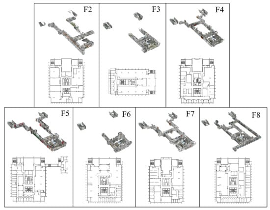
Figure 7.
The CAD drawings and smartphone’s 3D point clouds of the seven test cases.
The boundary of F5 was considerably larger than others because of a footbridge connecting a nearby building. Thus, the CAD drawing’s center x-coordinate was 12.238 m away from the reflection symmetry axis. Besides, the y-axis of the F3 drawing was perpendicular to its symmetry axis, which created a large rotation compared with the corresponding point clouds.
The colorful point clouds were scanned by a Google Tango AR phone (model: Lenovo Phab 2), which is reproducible by current mainstream ARCore phones or AR Kit phones (e.g., iPhone X and above and iPad Pro) [66]. The geometric error was less than 5 cm initially, but gradually ‘drifted’ over the scanning course. Except for F5, the as-built scans covered the public areas (e.g., corridors and stair networks) located in the center of the CAD drawings’ spatial bounding boxes. Note that the corridors scans can be incomplete for some stories.
We highlight the experimental results on F3 and F5, which would validate the RegARD method with a large rotation offset and central differences, respectively. All seven storeys were used for benchmarking the average performances in terms of accuracy and computational time.
4.2. Implementation Details
In the preprocessing, the buffering distance t in Equation (1) was set as 0.01 m, while the threshold of was set as 0.95. The two parameters of ODAS (i.e., in Equation (5) and the depth of the octree) were set to default values, while the solver was the default DIRECT, all as suggested in [49]. The default bounding parameter is set as 1.2. The DFO solvers listed in Section 3.3.4 were implemented by the open-source algorithmic libraries libcmaes (ver. 0.9.6.1) [67] and NLopt (ver. 2.6.2) [68] in C++ and Python. Besides, all the experiments were performed on (i) a laptop with an Intel Core i7 CPU (2.20 GHz, four cores), 16 GB of RAM, and Ubuntu 20.04 installed on Windows Subsystem for Linux 2 (WSL2) and (ii) a workstation with an Intel Core i7 CPU (2.9 GHz, 16 cores), 128 GB of RAM, and Ubuntu 20.04.
4.3. Generated Digital Twin Buildings
The resulted DTBs were created in the Industry Foundation Classes (IFC) format. As introduced in Section 3.2.1, we extracted the vertical structures, i.e., walls and openings, from CAD drawings and generated them into IfcWall and IfcDoor instances, along with the generated floors and ceilings as IfcSlab instances. The elevations and heights of IfcWall, IfcDoor, and IfcSlab were set according to the floor and ceiling elevations estimated as Section 3.2.2. Next, the RegARD method registered the scan point clouds to the design models, following by the texturing process. To enable the instance texturing in IFC, the geometry of instances is stored as IfcFacetedBrep with faces as IfcFace. Therefore, the external texture images could be linked to IfcFace by IfcImageTexture, IfcSurfaceStyleWithTextures, IfcSurfaceStyle, and IfcStyledItem; the coordinate mappings between the texture images and the IfcFace were given as IfcTextureMap and IfcTextureVertex.
As shown in Figure 8 (visualized in FZKViewer), those vertical and horizontal surfaces scanned in the color point cloud were successfully textured, with an average density of 1403 points/m. Coarse appearance was attached to the walls, doors, floors, and ceilings. The corresponding IFC instances could link the real material color as well as the pasted posters through the texture images. By this tight integration between the as-designed CAD models and the as-built point clouds, our approach enabled the digital twinning of buildings with geometry, semantics, and appearance simultaneously at a much more affordable cost.
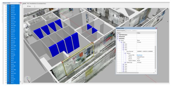
Figure 8.
Example DTB textured by the registered point cloud.
4.4. Registration Quantitative Analysis
The coarse registration was the core problem to resolve. Hence, we evaluated and compared the registration RMSD of RegARD with other state-of-the-art coarse registration methods, including CPD [35], Go-ICP [36], and GMMTree [37]. To further demonstrate the improvement by ARD, we compared the registration quality and efficiency with and without ARD. Besides, the DFO solvers are also a crucial factor for the final registration efficiency; we therefore tested the convergence of different DFO solvers to conclude the appropriate solver for our registration.
4.4.1. Registration Benchmarking
Table 2 reports the benchmarking results of RegARD and other registration algorithms. To control the total processing time, we set the number of iterations for all the algorithms as 100, the sampling interval of CAD drawings as 10 cm, and the sampling rate of point clouds as 0.001. The DFO solver of RegARD applied in this comparison was Nelder–Mead. Besides, the computational time of RegARD included the time of ARD, and that of Go-ICP includes the time for building distance transformation structures. Moreover, the outlier ratio of the source point cloud over the target was required by the CPD algorithm. They were set as , which are given in Table 1.

Table 2.
Registration metrics of RegARD and other coarse registration algorithms (100 iterations, 10 runs).
As shown in Table 2 and Figure 9, our algorithm showed significant advances in both registration accuracy and computational time above all the best baseline methods. RegARD reduced the RMSD by a considerable amount ranging from 24.87% to 60.17% compared with the baseline methods. Figure 9 shows the visual results of F2, F3, and F5. The results of CPD, Go-ICP, and GMMTree yielded obvious rotation or translation errors, while RegARD successfully registered as-designed and as-built data. Meanwhile, the computational time of RegARD on all the tested stories was shortened by 36.02 % to 83.06% compared with the most efficient baseline, i.e., GMMTree. On average, RegARD’s RMSD was 49.9% less than the best results of the baselines, while RegARD also saved 73.1% time cost. The RegARD’s results in Table 2 were very close to the global minima. By the decomposition as two sub-problems, the RegARD outperformed with only 100 iterations. Meanwhile, other coarse registration methods such as Go-ICP and GMMTree should search in a large solution space to approach the global minima gradually. Besides, since the asymptotic time complexity of RegARD was proportional to the number of source points, it took a longer computational time on F2, the point number of which was greater than others, as shown in Table 1.
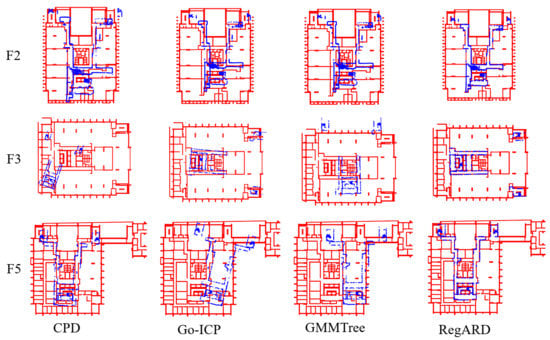
Figure 9.
Comparison of the registration results by different methods.
4.4.2. Regard Component Analysis
We further measured the ARD’s effects by comparing the registration with and without ARD solved by DFO. The sampling interval of CAD drawings was 10 cm and the sampling rate of the point clouds was 0.001. The DFO solver of RegARD was Nelder–Mead. The resulted metrics are reported in Table 3. The visual comparisons on F3 and F5 are presented in Figure 10. They can be summarized into three situations based on the metrics and the initial poses of point clouds and CAD models:

Table 3.
Metrics of registration with and without ARD (100 iterations, average of 10 runs).
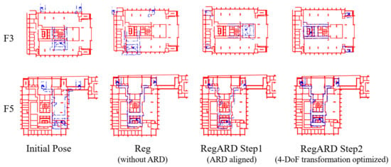
Figure 10.
Comparison of registration with and without ARD on F3 and F5.
- The inputs were close to the fittest transformation, e.g, the stories except for F3 and F5. The transformation between the sampled points of drawings and point clouds could be solved in a limited number of iterations. The results with 100 iterations were close to the converged solutions.
- There was a large translation between the initial poses of the two inputs, e.g., F5. The DFO solvers could optimize these translations to optima or sub-optima, with or without ARD. This could be verified by the F5’s RMSDs in Table 3, the visual results in Figure 10, and the RMSD curves in Figure 11.
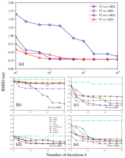 Figure 11. RMSDs with different numbers of iterations on F3 and F5. The best RMSDs among all the DFO solvers and the individual RMSDs are shown in (a) and the group of (b–e), respectively.
 - There was a large rotation between the initial poses of the two inputs, e.g., F3. This was the most challenging situation. As shown in Table 3, the registration without ARD was recorded an RMSD that was 4.5 times RegARD’s. The corresponding visual results of F3 and the RMSD convergence curves are presented in Figure 10 and Figure 11a, respectively. The curve comparison in Figure 11a demonstrated a considerably faster convergence with ARD. This result proved the argument in Section 3.3: rotation was a crucial DoF that could trap optimization algorithms in the problem equipping with strong self-similarities (e.g., building interiors). By decomposing the optimization of rotation and other DoFs, RegARD enabled the problem to be solved around 100 iterations.
Moreover, to select appropriate DFO solvers for building interior registration, we compared different DFO solvers, as shown in Figure 11b–e. The sampling interval of drawings was 1 cm, while the point clouds’ sampling rate was 0.001. All results were the average values of 10 independent runs. SBPLX, BOBYQA, and Nelder–Mead showed a high degree of efficiency and robustness when ARD was applied. Besides, both DIRECT and CMAES converged to find the best objective value if the number k of iterations was large enough. We also noticed that DIRECT and CMAES performed well at solving problems with many local minima, e.g., the F3 case with a large rotation and the F5 case with a large translation. Besides, MMA and MLSL were inappropriate or unstable regardless of ARD. Therefore, SBPLX, BOBYQA, and Nelder-Mead were the appropriate choices for RegARD with architectural reflection symmetries, while DIRECT and CMAES were more robust for registration without architectural reflection detection.
5. Discussion
In this study, we present a digital twinning approach based on low-cost data sources: point clouds captured by smartphones and available 2D CAD drawings for existing buildings. The critical part of our approach is the RegARD method to register point clouds with drawings. The theoretical breakthrough of RegARD is using the architectural reflection symmetry to successfully isolate the optimization rotation from the DoFs. As a result, the challenging registration of noisy and self-similar indoor point clouds becomes solvable through a two-step process. Moreover, together with the preprocessing and the 3D generation and texturing, our approach can generate DTBs with parametric geometry, rich semantics, and realistic appearance in a short processing time.
However, there are still some limitations and possible improvement directions in our approach, including:
- Registration quality: RegARD is a rigid registration method aiming at applying a global transformation to align indoor point clouds and CAD drawings. However, there could be local misalignment as well as translation and rotation drifts which cannot be robustly registered with only one global rigid transformation. The right top of F3 and the left top of F5 shown in Figure 10 are examples. To resolve this issue, the rigid alignment with the non-rigid corrections or piece-wise rigid registration [71] can be applied. Moreover, as-designed data, such as floor plans, can serve as a priori information to make proper assumptions on the deformations and guide the piece-wise segmentation of point clouds. For example, an indoor point cloud can be segmented into rooms and represented as a graph. Then, rigid transformations can be estimated on the nodes and edges to counteract the local misalignment or drifts.
- Semantics richness: in Section 3.2.1, this paper applies a thickness filter to extraction of wall instances from the CAD drawings. The filter has a limited capability in extracting vertical structures with square cross sections, though. Moreover, the vertical structures could be further classified, e.g., as external walls, inner walls, windows, and sliding doors. One possible way is to replace the thickness filter in this paper with supervised-learning-based classifiers, such as Decision Tree and Support-Vector Machine. Besides, it is also possible to perform object detection and semantic/instance segmentation on point clouds to attach more detailed semantics to IFC elements.
- Appearance quality: as shown in Figure 12, the resolution of the texture images is not high enough and defects such as blurring exist. This is a result of several reasons, such as the limitations of the scanning sensors, embedded Simultaneously Localization And Mapping (SLAM) algorithms, and unavoidable dynamic objects and texture lacking in the scanned environment. This issue can be improved by using the recent and even the next generations of consumer-level scanning devices with advanced sensors or embedded SLAM algorithms for point cloud collection.
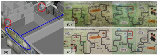 Figure 12. Temporary construction works and indoor textures in the DTB. (a) Temporary construction works circled in red; (b) textures in the DTB; (c) ground truth of the texture.
 - Processing time: the speed of the whole pipeline can be improved. For example, the asymptotic time complexity of RegARD is proportional to the number of source points, meaning the processing time can grow fast when the point number grows. This issue can be mitigated by applying weighted sampling [49] to reduce the processing scale of point clouds.
- Availability of reflection symmetry: when a building is asymmetric or with other types of symmetry, e.g., rotation or translation, rather than reflection, we can directly optimize the transformation without reflection detection. Examples without reflection detection are given in Table 3 and Figure 10. Moreover, because there is less self-similarity of asymmetric buildings, there are fewer local minima to trap the optimization.
- Inconsistency detection: there could be inconsistencies between the as-built and as-designed data. For example, the two red circles in Figure 12a show the on-going temporary construction work on the F2 of Knowles building. The temporary work covered one pathway between two soundproof curtains. These consistencies can cause a larger RMSD in registration or texturing noise. Inconsistency detection should be further exploited to improve the registration and final realistic models. At the same time, it is also desirable for maintenance and renovations.
6. Conclusions
Digital twin buildings (DTBs) are increasingly demanded by GIScience, manufacturing, robotics, mapping, and AECO industries. However, creating DTBs with parametric geometry, rich semantics, and realistic appearances with limited labor, device, and time cost is very challenging. This paper proposes a prototype method named ‘Registration based on Architectural Reflection Detection’ (RegARD) for high-quality and low-cost DTBs. Our approach exploits two low-cost data sources: 3D point clouds captured by ubiquitous mobile devices and widely available 2D drawings of existing buildings. Pilot experiments showed the RegARD can register smartphones’ point clouds with CAD drawings in high quality and efficiency. Based on the results of the RegARD, DTBs can be automatically generated with realistic textures mapped from point clouds as well as parametric geometry and rich semantics parsed from drawings.
Multiple directions of future work can be depicted from the findings and limitations of this paper. First, since the first coarse registration towards digital twin building creation is solved by the RegARD method, researchers can explore the seamless integration of indoor texture, objects, and topologies in the as-built 3D scans and the building structures and systems in the as-designed 2D drawings and 3D extrusions. Some researchers may be interested in adopting the first step of RegARD to other 3D registration or modeling methods. Another research opportunity is transforming the rigid indoor 3D point clouds into flexibly constrained networks of segmented rooms and spaces. One possible direction for practitioners is to migrate the RegARD method efficiently from single-threading computer CPUs to smart devices’ ARM architectures. The authors are optimistic that digital twin buildings in the future will be an approachable and functional reality rather than a rhetoric term.
Author Contributions
Conceptualization, Y.W. and F.X.; methodology, Y.W.; software, Y.W. and J.S.; validation, Y.W., J.S. and F.X.; data curation, Y.W. and F.X.; writing—original draft preparation, Y.W.; writing—review and editing, J.S. and F.X.; funding acquisition, F.X. All authors have read and agreed to the published version of the manuscript.
Funding
The work presented in this paper was financially supported by the Research Grants Council (RGC) of Hong Kong SAR under grant numbers 17200218 and 27200520. The APC was funded by the RGC.
Data Availability Statement
The source code of the latest version of RegARD is available at https://github.com/eiiijiiiy/RegARD (Updated on 30 April 2021). The test dataset is available in the source code. Local data are available from the corresponding author upon reasonable request.
Acknowledgments
We would like to express our gratitude to the Academic Editor and anonymous reviewers for the constructive suggestions to improve the quality of this paper.
Conflicts of Interest
The authors declare no conflict of interest.
References
- Xue, F.; Chiaradia, A.; Webster, C.J.; Liu, D.; Xu, J.; Lu, W. Personalized walkability assessment for pedestrian paths: An as-built BIM approach using ubiquitous augmented reality (AR) smartphone and deep transfer learning. In Proceedings of the 23rd International Symposium on the Advancement of Construction Management and Real Estate, Guiyang, China, 24–27 August 2018. [Google Scholar]
- Wen, C.; Pan, S.; Wang, C.; Li, J. An indoor backpack system for 2-D and 3-D mapping of building interiors. IEEE Geosci. Remote Sens. Lett. 2016, 13, 992–996. [Google Scholar] [CrossRef]
- Lim, K.Y.H.; Zheng, P.; Chen, C.H. A state-of-the-art survey of Digital Twin: Techniques, engineering product lifecycle management and business innovation perspectives. J. Intell. Manuf. 2019, 31, 1313–1337. [Google Scholar] [CrossRef]
- Khajavi, S.H.; Motlagh, N.H.; Jaribion, A.; Werner, L.C.; Holmström, J. Digital twin: Vision, benefits, boundaries, and creation for buildings. IEEE Access 2019, 7, 147406–147419. [Google Scholar] [CrossRef]
- Xue, F.; Lu, W.; Chen, Z.; Webster, C.J. From LiDAR point cloud towards digital twin city: Clustering city objects based on Gestalt principles. ISPRS J. Photogramm. Remote Sens. 2020, 167, 418–431. [Google Scholar] [CrossRef]
- Bianchini, C.; Nicastro, S. From BIM to H-BIM. In Proceedings of the 2018 3rd Digital Heritage International Congress (DigitalHERITAGE) Held Jointly with 2018 24th International Conference on Virtual Systems & Multimedia (VSMM 2018), San Francisco, CA, USA, 26–30 October 2018; pp. 1–4. [Google Scholar] [CrossRef]
- Attenni, M. Informative Models for Architectural Heritage. Heritage 2019, 2, 2067–2089. [Google Scholar] [CrossRef]
- NIC. Data for the Public Good. 2017. Available online: https://nic.org.uk/app/uploads/Data-for-the-Public-Good-NIC-Report.pdf (accessed on 10 May 2021).
- Xue, F.; Guo, H.; Lu, W. Digital twinning of construction objects: Lessons learned from pose estimation methods. In Proceedings of the 37th Information Technology for Construction Conference (CIB W78), São Paulo, Brazil, 2–4 June 2020. [Google Scholar] [CrossRef]
- Xue, F.; Lu, W.; Chen, K.; Zetkulic, A. From semantic segmentation to semantic registration: Derivative-Free Optimization–based approach for automatic generation of semantically rich as-built Building Information Models from 3D point clouds. J. Comput. Civ. Eng. 2019, 33, 04019024. [Google Scholar] [CrossRef]
- Lu, Q.; Chen, L.; Li, S.; Pitt, M. Semi-automatic geometric digital twinning for existing buildings based on images and CAD drawings. Autom. Constr. 2020, 115, 103183. [Google Scholar] [CrossRef]
- Boje, C.; Guerriero, A.; Kubicki, S.; Rezgui, Y. Towards a semantic Construction Digital Twin: Directions for future research. Autom. Constr. 2020, 114, 103179. [Google Scholar] [CrossRef]
- Xue, F.; Wu, L.; Weisheng, L. Semantic enrichment of building and city information models: A ten-year review. Adv. Eng. Inform. 2021, 47, 101245. [Google Scholar] [CrossRef]
- Xu, H.; Yu, L.; Fei, S. Hand-held 3-D reconstruction of large-scale scene with kinect sensors based on surfel and video sequences. IEEE Geosci. Remote Sens. Lett. 2018, 15, 1842–1846. [Google Scholar] [CrossRef]
- Bueno, M.; Bosché, F.; González-Jorge, H.; Martínez-Sánchez, J.; Arias, P. 4-Plane congruent sets for automatic registration of as-is 3D point clouds with 3D BIM models. Autom. Constr. 2018, 89, 120–134. [Google Scholar] [CrossRef]
- Endres, F.; Hess, J.; Sturm, J.; Cremers, D.; Burgard, W. 3-D mapping with an RGB-D camera. IEEE Trans. Robot. 2013, 30, 177–187. [Google Scholar] [CrossRef]
- Linowes, J.; Babilinski, K. Augmented Reality for Developers: Build Practical Augmented Reality Applications with Unity, ARCore, ARKit, and Vuforia; Packt Publishing Ltd.: Birmingham, UK, 2017. [Google Scholar]
- Xu, J.; Xue, F.; Chiaradia, A.; Lu, W.; Cao, J. Indoor-Outdoor Navigation without Beacons: Compensating Smartphone AR Positioning Errors with 3D Pedestrian Network. In Construction Research Congress 2020: Infrastructure Systems and Sustainability; American Society of Civil Engineers: Reston, VA, USA, 2020; pp. 444–452. [Google Scholar] [CrossRef]
- Gimenez, L.; Robert, S.; Suard, F.; Zreik, K. Automatic reconstruction of 3D building models from scanned 2D floor plans. Autom. Constr. 2016, 63, 48–56. [Google Scholar] [CrossRef]
- Han, J.; Yin, P.; He, Y.; Gu, F. Enhanced ICP for the registration of large-scale 3D environment models: An experimental study. Sensors 2016, 16, 228. [Google Scholar] [CrossRef]
- Lin, W.Y.; Liu, S.; Jiang, N.; Do, M.N.; Tan, P.; Lu, J. RepMatch: Robust feature matching and pose for reconstructing modern cities. In Proceedings of the European Conference on Computer Vision, Amsterdam, The Netherlands, 8–16 October 2016; Springer: Cham, Switzerland, 2016; pp. 562–579. [Google Scholar] [CrossRef]
- Hansen, N.; Müller, S.D.; Koumoutsakos, P. Reducing the time complexity of the derandomized evolution strategy with covariance matrix adaptation (CMA-ES). Evol. Comput. 2003, 11, 1–18. [Google Scholar] [CrossRef]
- Jones, D.R.; Perttunen, C.D.; Stuckman, B.E. Lipschitzian optimization without the Lipschitz constant. J. Optim. Theory Appl. 1993, 79, 157–181. [Google Scholar] [CrossRef]
- Nelder, J.; Mead, R. A simplex method for function minimization. Comput. J. 1965, 7, 308–313. [Google Scholar] [CrossRef]
- Johnson, A.E.; Hebert, M. Efficient multiple model recognition in cluttered 3-D scenes. In Proceedings of the 1998 IEEE Computer Society Conference on Computer Vision and Pattern Recognition (Cat. No. 98CB36231), Santa Barbara, CA, USA, 25 June 1998; pp. 671–677. [Google Scholar] [CrossRef]
- Chua, C.S.; Jarvis, R. Point signatures: A new representation for 3d object recognition. Int. J. Comput. Vis. 1997, 25, 63–85. [Google Scholar] [CrossRef]
- Rusu, R.B.; Blodow, N.; Beetz, M. Fast point feature histograms (FPFH) for 3D registration. In Proceedings of the 2009 IEEE International Conference on Robotics and Automation, Kobe, Japan, 12–17 May 2009; pp. 3212–3217. [Google Scholar] [CrossRef]
- Zeng, A.; Song, S.; Nießner, M.; Fisher, M.; Xiao, J.; Funkhouser, T. 3DMatch: Learning Local Geometric Descriptors from RGB-D Reconstructions. In Proceedings of the 2017 IEEE Conference on Computer Vision and Pattern Recognition (CVPR), Honolulu, HI, USA, 21–26 July 2017; pp. 199–208. [Google Scholar] [CrossRef]
- Choy, C.; Park, J.; Koltun, V. Fully Convolutional Geometric Features. In Proceedings of the 2019 IEEE/CVF International Conference on Computer Vision (ICCV), Seoul, Korea, 27 October–2 November 2019; pp. 8957–8965. [Google Scholar] [CrossRef]
- Yew, Z.J.; Lee, G.H. 3DFeat-Net: Weakly Supervised Local 3D Features for Point Cloud Registration. In Proceedings of the European Conference on Computer Vision, Munich, Germany, 8–14 September 2018; Springer: Cham, Switzerland, 2018; pp. 630–646. [Google Scholar] [CrossRef]
- Deng, H.; Birdal, T.; Ilic, S. PPFNet: Global Context Aware Local Features for Robust 3D Point Matching. In Proceedings of the 2018 IEEE/CVF Conference on Computer Vision and Pattern Recognition, Salt Lake City, UT, USA, 18–22 June 2018; pp. 195–205. [Google Scholar] [CrossRef]
- Besl, P.; McKayN, N. A method for registration of 3-D shapes. IEEE Trans. Pattern Anal. Mach. Intell. 1992, 14, 239–256. [Google Scholar] [CrossRef]
- Chen, Y.; Medioni, G. Object modelling by registration of multiple range images. Image Vis. Comput. 1992, 10, 145–155. [Google Scholar] [CrossRef]
- Rusinkiewicz, S.; Levoy, M. Efficient variants of the ICP algorithm. In Proceedings of the Third International Conference on 3-D Digital Imaging and Modeling, Quebec City, QC, Canada, 28 May–1 June 2001; pp. 145–152. [Google Scholar] [CrossRef]
- Myronenko, A.; Song, X. Point set registration: Coherent point drift. IEEE Trans. Pattern Anal. Mach. Intell. 2010, 32, 2262–2275. [Google Scholar] [CrossRef] [PubMed]
- Yang, J.; Li, H.; Campbell, D.; Jia, Y. Go-ICP: A globally optimal solution to 3D ICP point-set registration. IEEE Trans. Pattern Anal. Mach. Intell. 2015, 38, 2241–2254. [Google Scholar] [CrossRef] [PubMed]
- Eckart, B.; Kim, K.; Kautz, J. Hgmr: Hierarchical gaussian mixtures for adaptive 3d registration. In Proceedings of the European Conference on Computer Vision (ECCV), Munich, Germany, 8–14 September 2018; pp. 705–721. [Google Scholar]
- Yang, H.; Shi, J.; Carlone, L. TEASER: Fast and certifiable point cloud registration. IEEE Trans. Robot. 2020, 37, 314–333. [Google Scholar] [CrossRef]
- Wang, Y.; Solomon, J. Deep Closest Point: Learning Representations for Point Cloud Registration. In Proceedings of the 2019 IEEE/CVF International Conference on Computer Vision (ICCV), Seoul, Korea, 27 October–2 November 2019; pp. 3522–3531. [Google Scholar] [CrossRef]
- Choy, C.; Dong, W.; Koltun, V. Deep Global Registration. In Proceedings of the 2020 IEEE/CVF Conference on Computer Vision and Pattern Recognition (CVPR), Seattle, WA, USA, 14–19 June 2020; pp. 2511–2520. [Google Scholar] [CrossRef]
- Xu, Y.; Boerner, R.; Yao, W.; Hoegner, L.; Stilla, U. Pairwise coarse registration of point clouds in urban scenes using voxel-based 4-planes congruent sets. ISPRS J. Photogramm. Remote Sens. 2019, 151, 106–123. [Google Scholar] [CrossRef]
- Chen, S.; Nan, L.; Xia, R.; Zhao, J.; Wonka, P. PLADE: A Plane-Based Descriptor for Point Cloud Registration With Small Overlap. IEEE Trans. Geosci. Remote Sens. 2019, 58, 2530–2540. [Google Scholar] [CrossRef]
- Zolanvari, S.I.; Laefer, D.F.; Natanzi, A.S. Three-dimensional building façade segmentation and opening area detection from point clouds. ISPRS J. Photogramm. Remote Sens. 2018, 143, 134–149. [Google Scholar] [CrossRef]
- Polewski, P.; Yao, W. Scale invariant line-based co-registration of multimodal aerial data using L1 minimization of spatial and angular deviations. ISPRS J. Photogramm. Remote Sens. 2019, 152, 79–93. [Google Scholar] [CrossRef]
- Chen, K.; Lu, W.; Xue, F.; Tang, P.; Li, L.H. Automatic building information model reconstruction in high-density urban areas: Augmenting multi-source data with architectural knowledge. Autom. Constr. 2018, 93, 22–34. [Google Scholar] [CrossRef]
- Wang, H.; Zhang, W.; Chen, Y.; Chen, M.; Yan, K. Semantic decomposition and reconstruction of compound buildings with symmetric roofs from LiDAR data and aerial imagery. Remote Sens. 2015, 7, 13945–13974. [Google Scholar] [CrossRef]
- Ceylan, D.; Mitra, N.J.; Zheng, Y.; Pauly, M. Coupled structure-from-motion and 3D symmetry detection for urban facades. ACM Trans. Graph. (TOG) 2014, 33, 1–15. [Google Scholar] [CrossRef]
- Cheng, L.; Wu, Y.; Chen, S.; Zong, W.; Yuan, Y.; Sun, Y.; Zhuang, Q.; Li, M. A symmetry-based method for LiDAR point registration. IEEE J. Sel. Top. Appl. Earth Obs. Remote Sens. 2017, 11, 285–299. [Google Scholar] [CrossRef]
- Xue, F.; Lu, W.; Webster, C.J.; Chen, K. A derivative-free optimization-based approach for detecting architectural symmetries from 3D point clouds. ISPRS J. Photogramm. Remote Sens. 2019, 148, 32–40. [Google Scholar] [CrossRef]
- Xue, F.; Lu, W.; Chen, K.; Webster, C.J. BIM reconstruction from 3D point clouds: A semantic registration approach based on multimodal optimization and architectural design knowledge. Adv. Eng. Inform. 2019, 42, 100965. [Google Scholar] [CrossRef]
- Bassier, M.; Vergauwen, M. Unsupervised reconstruction of Building Information Modeling wall objects from point cloud data. Autom. Constr. 2020, 120, 103338. [Google Scholar] [CrossRef]
- Wang, C.; Hou, S.; Wen, C.; Gong, Z.; Li, Q.; Sun, X.; Li, J. Semantic line framework-based indoor building modeling using backpacked laser scanning point cloud. ISPRS J. Photogramm. Remote Sens. 2018, 143, 150–166. [Google Scholar] [CrossRef]
- Nikoohemat, S.; Diakité, A.A.; Zlatanova, S.; Vosselman, G. Indoor 3D reconstruction from point clouds for optimal routing in complex buildings to support disaster management. Autom. Constr. 2020, 113, 103109. [Google Scholar] [CrossRef]
- Ochmann, S.; Vock, R.; Klein, R. Automatic reconstruction of fully volumetric 3D building models from oriented point clouds. ISPRS J. Photogramm. Remote Sens. 2019, 151, 251–262. [Google Scholar] [CrossRef]
- Jung, J.; Stachniss, C.; Ju, S.; Heo, J. Automated 3D volumetric reconstruction of multiple-room building interiors for as-built BIM. Adv. Eng. Inform. 2018, 38, 811–825. [Google Scholar] [CrossRef]
- Murali, S.; Speciale, P.; Oswald, M.R.; Pollefeys, M. Indoor Scan2BIM: Building information models of house interiors. In Proceedings of the 2017 IEEE/RSJ International Conference on Intelligent Robots and Systems (IROS), Vancouver, BC, Canada, 24–28 September 2017; pp. 6126–6133. [Google Scholar] [CrossRef]
- Liu, C.; Wu, J.; Kohli, P.; Furukawa, Y. Raster-to-Vector: Revisiting Floorplan Transformation. In Proceedings of the 2017 IEEE International Conference on Computer Vision (ICCV), Venice, Italy, 22–29 October 2017; pp. 2214–2222. [Google Scholar] [CrossRef]
- Wu, Y.; Shang, J.; Chen, P.; Zlatanova, S.; Hu, X.; Zhou, Z. Indoor mapping and modeling by parsing floor plan images. Int. J. Geogr. Inf. Sci. 2020. [Google Scholar] [CrossRef]
- Wijmans, E.; Furukawa, Y. Exploiting 2D Floorplan for Building-Scale Panorama RGBD Alignment. In Proceedings of the 2017 IEEE Conference on Computer Vision and Pattern Recognition (CVPR), Honolulu, HI, USA, 21–26 July 2017; pp. 1427–1435. [Google Scholar] [CrossRef]
- Adams, R.; Bischof, L. Seeded region growing. IEEE Trans. Pattern Anal. Mach. Intell. 1994, 16, 641–647. [Google Scholar] [CrossRef]
- Turner, E.; Zakhor, A. Watertight as-built architectural floor plans generated from laser range data. In Proceedings of the 2012 Second International Conference on 3D Imaging, Modeling, Processing, Visualization & Transmission, Zurich, Switzerland, 13–15 October 2012; pp. 316–323. [Google Scholar] [CrossRef]
- Sun, C.; Sherrah, J. 3D symmetry detection using the extended Gaussian image. IEEE Trans. Pattern Anal. Mach. Intell. 1997, 19, 164–168. [Google Scholar] [CrossRef]
- Kazhdan, M. An approximate and efficient method for optimal rotation alignment of 3D models. IEEE Trans. Pattern Anal. Mach. Intell. 2007, 29, 1221–1229. [Google Scholar] [CrossRef]
- Rowan, T.H. Functional Stability Analysis of Numerical Algorithms. Ph.D. Thesis, The University of Texas at Austin, Austin, TX, USA, 1990. [Google Scholar]
- Telea, A. An image inpainting technique based on the fast marching method. J. Graph. Tools 2004, 9, 23–34. [Google Scholar] [CrossRef]
- Taberna, G.A.; Guarnieri, R.; Mantini, D. SPOT3D: Spatial positioning toolbox for head markers using 3D scans. Sci. Rep. 2019, 9, 12813. [Google Scholar] [CrossRef]
- Benazera, E. Libcmaes: A Multithreaded C++11 Library with Python Bindings for High Performance Blackbox Stochastic Optimization Using the CMA-ES Algorithm for Covariance Matrix Adaptation Evolution Strategy. 2020. Available online: https://github.com/beniz/libcmaes (accessed on 2 November 2020).
- Steven, J. NLopt: A Free/Open-Source Library for Nonlinear Optimization. 2020. Available online: https://nlopt.readthedocs.io/en/latest/ (accessed on 2 November 2020).
- Tanaka, K.; Schmitz, P.; Ciganovic, M.; Kumar, P. Probreg: Probablistic Point Cloud Registration Library. 2020. Available online: https://probreg.readthedocs.io/en/latest/ (accessed on 2 November 2020).
- Srinivasan, R. Go-icp_cython: A Cython Version of the Original Go-ICP. Available online: https://github.com/aalavandhaann/go-icp_cython (accessed on 2 November 2020).
- Tam, G.K.; Cheng, Z.Q.; Lai, Y.K.; Langbein, F.C.; Liu, Y.; Marshall, D.; Martin, R.R.; Sun, X.F.; Rosin, P.L. Registration of 3D point clouds and meshes: A survey from rigid to nonrigid. IEEE Trans. Vis. Comput. Graph. 2012, 19, 1199–1217. [Google Scholar] [CrossRef]
Publisher’s Note: MDPI stays neutral with regard to jurisdictional claims in published maps and institutional affiliations. |
© 2021 by the authors. Licensee MDPI, Basel, Switzerland. This article is an open access article distributed under the terms and conditions of the Creative Commons Attribution (CC BY) license (https://creativecommons.org/licenses/by/4.0/).