Article

Cloud Detection Based on High Resolution Stereo Pairs of the Geostationary Meteosat Images

by
Sahar Dehnavi
1,2,*,
Yasser Maghsoudi
1,
Klemen Zakšek
3,4,
Mohammad Javad Valadan Zoej
1,
Gunther Seckmeyer
2 and
Vladimir Skripachev
5
1
Geomatics Engineering Faculty, K.N. Toosi University of Technology, Tehran 19967-15433, Iran
2
Institut für Meteorologie und Klimatologie, Leibniz Universität Hannover, 30419 Hannover, Germany
3
ROSEN group, Am Seitenkanal 8, 49811 Lingen, Germany
4
Faculty of Civil and Geodetic Engineering, University of Ljubljana, Jamova 2, 1000 Ljubljana, Slovenia
5
The Federal Center of Expertize and Analysis, Moscow, Russia
*
Author to whom correspondence should be addressed.
Remote Sens. 2020, 12(3), 371; https://doi.org/10.3390/rs12030371
Submission received: 5 January 2020 / Revised: 17 January 2020 / Accepted: 20 January 2020 / Published: 23 January 2020
(This article belongs to the Section Atmospheric Remote Sensing)

Abstract

:
Due to the considerable impact of clouds on the energy balance in the atmosphere and on the earth surface, they are of great importance for various applications in meteorology or remote sensing. An important aspect of the cloud research studies is the detection of cloudy pixels from the processing of satellite images. In this research, we investigated a stereographic method on a new set of Meteosat images, namely the combination of the high resolution visible (HRV) channel of the Meteosat-8 Indian Ocean Data Coverage (IODC) as a stereo pair with the HRV channel of the Meteosat Second Generation (MSG) Meteosat-10 image at 0° E. In addition, an approach based on the outputs from stereo analysis was proposed to detect cloudy pixels. This approach is introduced with a 2D-scatterplot based on the parallax value and the minimum intersection distance. The mentioned scatterplot was applied to determine/detect cloudy pixels in various image subsets with different amounts of cloud cover. Apart from the general advantage of the applied stereography method, which only depends on geometric relationships, the cloud detection results are also improved because: (1) The stereo pair is the HRV bands of the Spinning Enhanced Visible and InfraRed Imager (SEVIRI) sensor, with the highest spatial resolution available from the Meteosat geostationary platform; and (2) the time difference between the image pairs is nearly 5 s, which improves the matching results and also decreases the effect of cloud movements. In order to prove this improvement, the results of this stereo-based approach were compared with three different reflectance-based target detection techniques, including the adaptive coherent estimator (ACE), constrained energy minimization (CEM), and matched filter (MF). The comparison of the receiver operating characteristics (ROC) detection curves and the area under these curves (AUC) showed better detection results with the proposed method. The AUC value was 0.79, 0.90, 0.90, and 0.93 respectively for ACE, CEM, MF, and the proposed stereo-based detection approach. The results of this research shall enable a more realistic modelling of down-welling solar irradiance in the future.

Graphical Abstract

1. Introduction

One of the most interesting features of Earth, as seen from space, is the ever-changing distribution of clouds. They are as natural as anything we encounter in our daily lives. As they float above us, we hardly give their presence a second thought. And yet, clouds have an enormous influence on Earth’s energy balance, climate, and weather [1]. Clouds have widespread effects on the energy balance of the Earth and the atmosphere. They cause severe atmospheric changes in both the vertical and horizontal directions [2]. Depending on their characteristics and height in the atmosphere, clouds can influence the energy balance in different ways. Clouds can block a significant portion of the Sun’s incoming radiation from reaching the Earth’s surface [1]. However, what actually are clouds? Clouds are either optically thick entities that cover the surface, or semi-transparent if they are above homogeneous surface.
People have been keeping records and observing clouds over generations. The traditional ground-based records have made important contributions to the understanding of clouds, but they do not provide scientists with the required detailed global cloud database to help them continue to improve model representations of clouds. Specifically, scientists require frequent observations (at least daily), over global scales (including remote ocean and land regions), and at wavelengths throughout the electromagnetic spectrum (visible, infrared, and microwave portions of the spectrum). Ground-based measurements make significant contributions, particularly to temporal coverage, but are limited to mostly land areas. Satellite observations complement and extend ground-based observations by providing increased spatial coverage and multiple observational capabilities [1]. The ability of remote sensing as a means for studying the atmosphere in larger scales has been well known for many years, and its ability to measure clouds’ characteristics and parameters has been proven in the last decades. An important aspect of cloud research is the detection of cloudy pixels from the image processing of satellite images. On the one hand, clouds are widespread in optical remote sensing images and cause a lot of difficulty in many remote sensing activities, such as land cover monitoring, environmental monitoring, and target recognizing [3]. On the other hand, they reduce the incoming surface solar irradiance, which is important in energy research. Hence, cloud detection for remote sensing images is often a necessary process among the important topics in meteorology, climatology, and remote sensing. So far, different methods have been proposed to detect clouds using satellite imagery [4,5,6]. In some of these methods, the cloud height information was used for their detection, like [4], in which a height threshold value was used for the detection of cloudy pixels [4,5,6]. This study was implemented over polar regions using data from an along track scanning radiometer (ATSR) sensor because of the difficult process of cloud identification over snow and ice due to their similar visible and thermal properties [7,8,9,10]. The same problem also occurs in bright and cold desert areas. In winter conditions, clear sky instants in the early morning or the late afternoon at desert locations are sometimes mistaken as clouds. A desert pixel may be seen as cold in the thermal and bright in the visible channels and therefore, it may be misinterpreted as cloud, for example, when using the advanced very high resolution radiometer (Avhrr) processing scheme over clouds, land, and ocean (APOLLO) cloud detection approach. This misinterpretation problem of the APOLLO still requires additional work to be solved [10,11].
On the other hand, considering that clouds are the greatest causes of solar radiation blocking, short-term cloud detection and forecasting with the highest available spatial resolution in wide areas with short revisit times can help to improve power plant operation and the available cloud products. Hence, the concentration of this research is to provide a basis for cloud detection based on its height information, which shall provide a possibility to improve the current available models (e.g., APOLLO) for the preparation of cloud products.
So far, several methods have been applied for cloud height estimation using remote sensing data [12], like light detection and ranging (LiDAR) and radio detection and ranging (RADAR) measurements [13,14], O2 A-band [15], CO2 absorption bands [16,17], comparison of the brightness temperature (BT) with the vertical atmospheric temperature profile [18,19], shadow lengths [18,20,21], backward trajectory modelling [22], optimal estimation [23,24,25,26], and stereography [27]. All these methods could provide a possibility for cloud detection based on the estimated height information. However, their possible benefits and drawbacks, discussed in detail in [19,28], helped us to narrow down the choices. Thus, the appropriate approach for cloud height estimation in this study was stereography because, as it was mentioned before, stereography is the only independent method for cloud-top height retrieval in passive remote sensing. The method is independent because it does not rely on ancillary data, such as temperature/pressure profiles [27]. This technique only depends on the basic geometric relationships of cloud features from at least two different viewing angles. The basis of this method is formed by the overlapping area of two adjusted images. Looking into the related literature [29,30,31,32,33,34,35,36] shows that the most important advantage of stereography is that this method requires no additional data and the side effect is the requirement for simultaneous data from two different viewing angles [37]. In recent years, several researchers tried to take advantage of this technique in their own topics using different kinds of satellite/airborne or ground-based images and for various purposes like the study of convective clouds [38], cumulonimbus clouds [39], volcanic ash [19,28], and the development of a system of cloud monitoring [40], or estimation of the height-resolved cloud motion vector (i.e., wind) [41], its height [42], and its shape and size [43,44]. In these studies, either a combination of two polar orbiting, two geostationary [28,45,46], one polar orbiting-one geostationary [19] sensors, or a pair of images from instruments with multi-angle observations [22] were used. Due to the short revisit time and wide spatial coverage of the available geostationary satellites like Meteosat, they were very commonly applied in previous research for cloud observations [28,38,39,40,45]. Nevertheless, in most of these studies, one stereo pair was chosen from the second-generation sensor, Spinning Enhanced Visible and InfraRed Imager (SEVIRI), and the second pair was from the first generation, i.e., Meteosat visible and infrared imager (MVIRI) or other satellites like Moderate Resolution Imaging Spectroradiometer (MODIS). Differences between the applied sensors resulted in various spatial/spectral resolutions between those two pairs, and they usually also had a high time difference. With the new changes in the Meteosat constellation, which is discussed in more detail in Section 2, it is now possible to take advantage of two image pairs from the same Meteosat Second Generation (MSG). Therefore, in this research, we aimed to get the High Resolution Visible (HRV) channel of the Meteosat-8 Indian Ocean Data Coverage (IODC) as a stereo pair with the HRV channel of another MSG image in the 0° E (i.e., Meteosat-10 in this research). It is worth mentioning that, Meteosat-10 has been relocated at 9.5° E since 20 March 2018 (after this study) while Meteosat-11 has been located at 0° W since 20 February 2018.
The advantages of this combination directly come from having a second-generation platform in the Indian Ocean region. These advantages include a higher spatial resolution (nominal 1 km spatial resolution instead of 3 km in other channels), higher number of spectral bands (12 instead of 3), and less revisit time (every 15 min in lieu of 30 min, which was the case for first generation) and as a result less time difference between image pairs (here 5 s). All the above-mentioned advantages make the stereo outputs, especially the matching results, more reliable. With the application of the HRV band, this research benefits from a higher resolution and shorter revisit times.
In summary, this paper presents an approach for cloud detection, based on the application of MSG’s HRV bands in a stereo method and a newly introduced 2D scatterplot space. A brief description of the used dataset is given in Section 2. Afterwards, Section 3 gives a detailed explanation of the stereography and the proposed cloud detection method. Moreover, well-known reflectance-based target detection techniques [7,8,9,10,11,16,47,48,49,50], which were used for an evaluation of the results, are also discussed in the same section (Section 3). At the end, the results of our study are reported in Section 4 and we discuss these results in Section 5 while we draw conclusions in Section 6.

2. Materials

The European Organization for the Exploitation of Meteorological Satellites (EUMETSAT) has operated the Meteosat series of satellites since 1977. Today, weather satellites scan the whole Earth. The Meteosat Data Collection Service is provided from 0° W, 9.5° E and on top of Indian Ocean locations. Each Meteosat satellite is expected to remain in orbit in an operable condition for at least seven years. The current policy is to keep two operable satellites in orbit and to launch a new satellite close to the date when the fuel in the elder of the two starts to run out. Spare Meteosat satellites have undertaken the IODC service since 1998. It was originally set up to support the international climate experiment INDOEX or the Indian Ocean Experiment, by providing Meteosat-5 imagery for the Indian Ocean area, for the duration of this experiment. Meteosat-7, which was from the first generation of this series, took over as an interim service in 2007 and remained as an IODC satellite (at 51.5°E) until 2017. However, the mission of this spacecraft ended in 2017 and the last disseminated Meteosat-7 image was on 31 March-2017 (for more details see https://www.eumetsat.int/website/home/Satellites/CurrentSatellites/Meteosat/index.html).
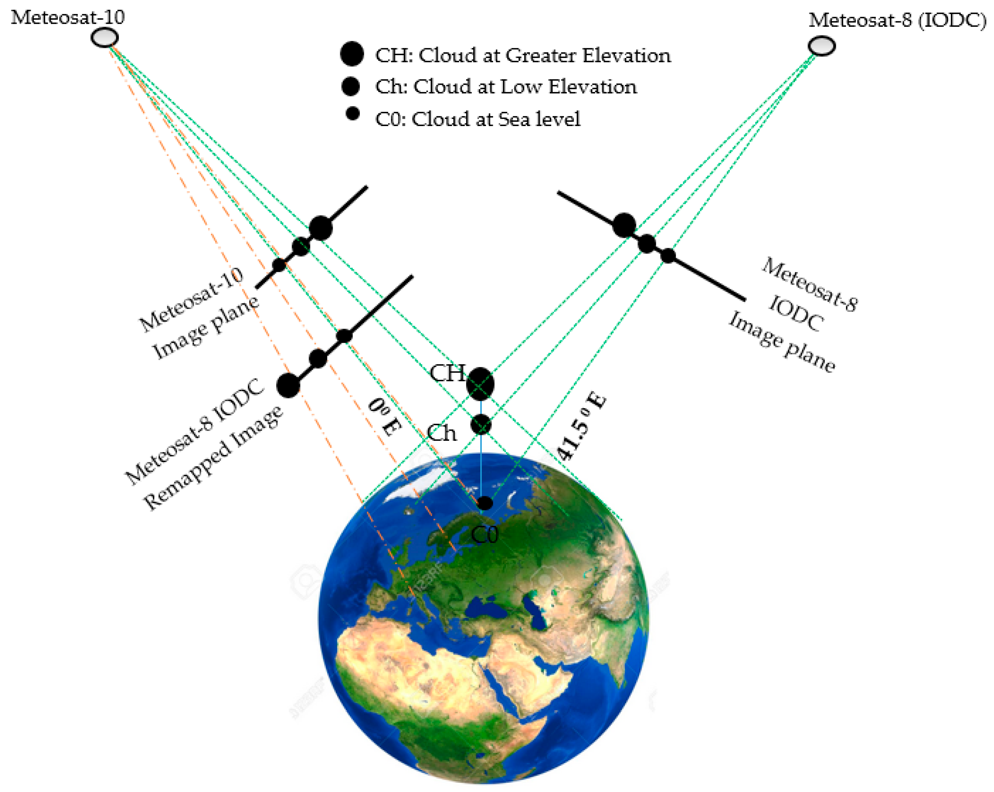
Hence, on 29 June 2016, EUMETSAT approved the proposal of relocating Meteosat-8 to 41.5°E, for the continuation of the Indian Ocean Data Coverage. Meteosat-8 arrived at 41.5°E on 21 September of the same year. The distribution of IODC Meteosat-8 data, in parallel to Meteosat-7 data, was planned to start on 4 October. In the first quarter of 2017, Meteosat-8 replaced Meteosat-7, which moved to its graveyard orbit. Meteosat-7 de-orbiting commenced on 3 April 2017 and the spacecraft’s final command was sent on 11 April 2017. Therefore, in 2017 the IODC service transitioned from Meteosat-7 to Meteosat-8. This relocation brought many benefits to the stereographic observation with Meteosat images. Meteosat-8 belongs to the second generation of Meteosat, i.e., MSG, and is much more capable than the Meteosat First Generation (MFG) like Meteosat-7. It delivers imagery from 12 instead of 3 spectral channels with higher spatial resolution and with an increased frequency, every 15 instead of 30 min. Of the 12 spectral channels, 11 provide measurements with a nominal resolution of 3 km at the sub-satellite point. The 12th so-called High Resolution Visible or HRV channel provides measurements with a nominal resolution of 1 km [51]. Therefore, the new policies of the EUMETSAT provided us the possibility to take advantage of two similar bands of the same sensor—SEVIRI—on board two Meteosat platforms with a spatial baseline of approximately about 30,600 km. One of the sensors looking to Earth at the longitude of 0° W and the other one pointing to the ground at 41.5° E. Therefore, they are applicable in the stereography method. In order to exploit the maximum spatial and temporal resolution of the two instruments, the HRV bands (0.6–0.9 μ m ) of both sensors were used [
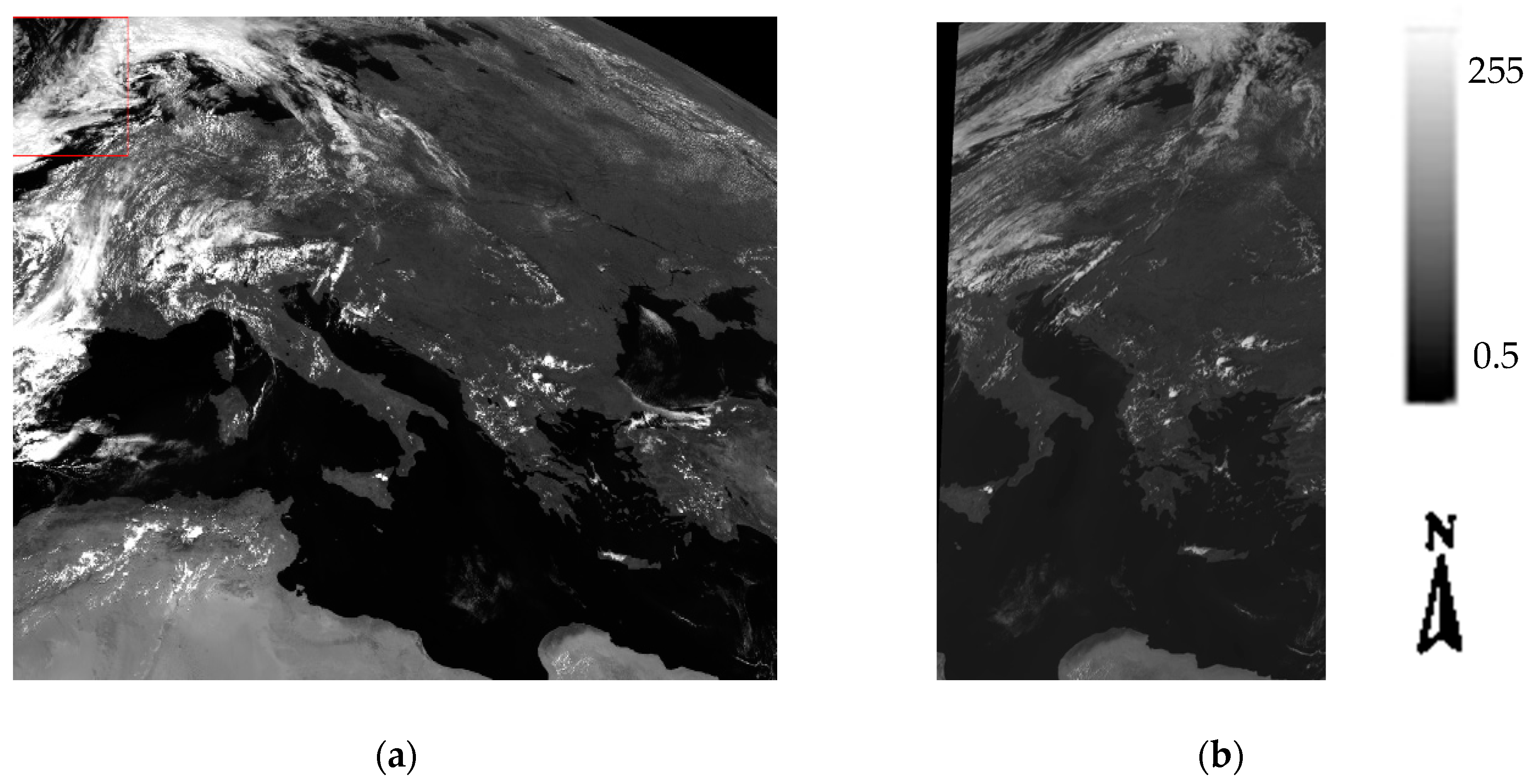
2]. However, it is worth mentioning that before the publication of this research paper, the Meteosat-10 platform has been replaced by Meteosat-9 RSS and located at 9.5° E since 20 March 2018, and afterwards Meteosat-11 has been located at 0° E since 20 February 2018. Therefore, similar research can be implemented using Meteosat-11 instead of Meteosat-10 image data. An overview of the selected stereo image pair in our study and the corresponding study area is shown in
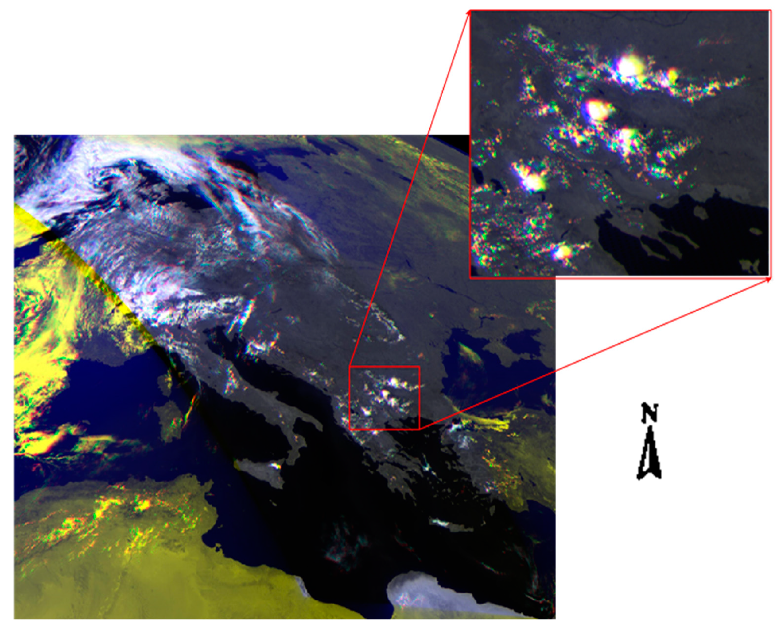
 Figure 1.
The introduced image data were downloaded from EUMETSAT data center (https://www.eumetsat.int/website/home/Data/DataDelivery/EUMETSATDataCentre/index.html), in level 1.5 and in High Rate Image Transfer (HRIT) mode. Level 1.5 image data corresponds to the geo-located and radiometrically pre-processed image data, ready for further processing, e.g., the extraction of meteorological products. Any spacecraft specific effects have been removed, and in particular, linearization, and equalization of the image radiometry has been performed for all SEVIRI channels. The on-board blackbody data has been processed. Both radiometric and geometric quality control information is included.
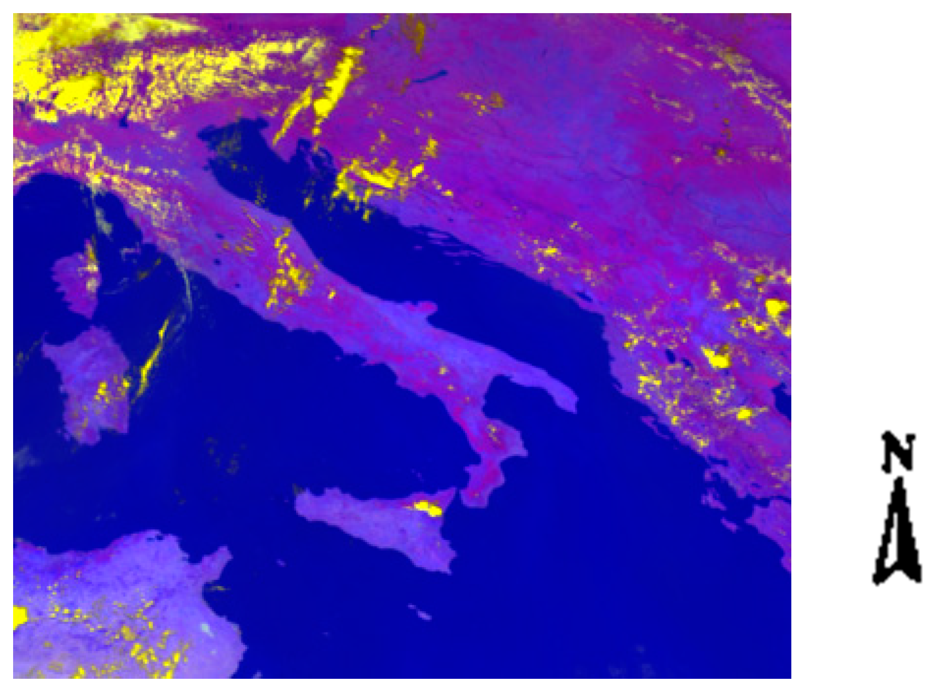
Moreover, in order to provide the possibility of comparing the resulting outputs from the proposed approach with other detection methods, multispectral non-HRV bands of a specific subset in the same region were also used. The color composite of the visible and near infrared spectral bands (VIS: 0.8, VIS: 0.6, IR: 8.7 μm), is shown in Figure 2.

3. Method

In this section, an overview of the different required steps to provide the stereo-based 2D scatterplot for cloud detection is discussed. In order to implement the idea of this research, several IDL (Interactive Data Language) routines were prepared. In the following subsections, the main part of these routines is explained, including data reading; preparation and preprocessing; stereo technique, including the three steps of re-gridding, image matching, and parallax estimation; and finally, cloud detection in the proposed 2D scatterplot. All these steps were implemented using IDL routines and part of them are made available in the Supplementary Materials of this paper. A general flowchart for implementing all the above-mentioned routines and steps is summarized in Figure 3.
At the end of this section, the common target detection techniques that were used for comparison analysis are also briefly discussed. However, these detection techniques are available in ENVI (Environment for Visualizing Images) software. Therefore, we performed this part of our analysis using this software.

3.1. Reading MSG Data

Our MSG image data were provided in HDF-5 format from the EUMETSAT website. In order to process the data, first an IDL routine was prepared, by which a TIFF (Tagged Image File Format) image file was generated from the original HRV band of the MSG dataset (see the first Supplementary Material (SM-1)). Afterwards, a separate routine was applied for reading image metadata information. As a result, the satellite position at the time of retrieval, ellipsoid parameters, required offsets, column and line numbers in the SEVIRI grid, and satellite sub-longitude as outputs of this routine were prepared. The above-mentioned outputs will be further used for the image geocoding (see Section 3.3.3). The beginning part of this routine, which introduces the input and output parameters, is presented in SM-2.

3.2. Data Preparation and Preprocessing

The entire processing and preparation step was also performed using several IDL routines and functions. For the preparation of the image data first, a Wallis filter [52] was applied to the input images (see SM-3), in order to improve the correlation analysis and image matching. The Wallis filter helps to locally enhance data contrast and texture in images [52], because the Wallis filter is a local image transform that approximates the gray mean and variance of different parts [53]. Namely, it increases the gray contrast of parts where the contrast is small and decreases gray contrast where the contrast is large. This filter works very well to get rid of uneven illumination [54] in the images.
Second step is the preparation of geolocation information for the images. SEVIRI images are available in a normalized geostationary projection system according to the Coordination Group for Meteorological Satellites [55]. This projection is defined in relation to the sub-satellite (nadir) longitude (0°W in the case of MSG). The conversion of image coordinates into geographical coordinates is described in [55]. For each image coordinate, the latitude and longitude are computed accordingly and saved in corresponding data sets. Likewise, satellite and solar geometry, i.e., zenith and azimuth angles, are calculated and saved. These coordinate conversions are implemented for the 1 km HRV channel in this study (see details in Section 3.3.3). For a list of input and output parameters that was used in the corresponding IDL routine, see SM-4.
After the preparation of image data, some other routines were prepared to make the stereography analysis of the pair of HRV images feasible. More details about the routines for stereo analysis and the method itself are discussed in the following subsections.

3.3. Stereography

According to all the previously mentioned pros and cons in different height estimation methods and the available Meteosat data, we used the stereography-based approach in this study. The height estimation in this research is based on the parallax, i.e., the apparent shift in cloud’s position as a result of viewing along different lines of sight from two multispectral radiometers onboard geostationary platforms, which were taken nearly concurrently. This value depends on the height of the cloud; the higher height the cloud is, the higher the parallax value and as a consequence the higher the apparent displacement (see Figure 4).
As is clear from Figure 4, when the cloud height is higher (H1 > H2), the parallax distance is also higher (P1 > P2). Therefore, the amount of parallax can be used as a measure for cloud height.
As it was mentioned by Zakšek et al., in 2013 and Merruci et al., 2016 [18,19], it is feasible to implement the stereography method in three steps.

3.3.1. Projection of Both Stereo Pairs into the Same Grid

In order to bring the stereo pairs in the same image grid, different interpolation methods [56] (e.g., bilinear [57], bi-cubic [57], inverse weighted distance (IWD) [58], etc.) can be applied. However, according to our previous experiences [28,52], the inverse weighted interpolation was applied in this study, as the IWD interpolation technique minimizes the interpolation artefacts.
In fact, in this research, the HRV band from the Meteosat-8 (IODC) was projected (remapped) into the Meteosat-10 grid using IWD interpolation. Figure 5 shows this remapping (re-projection) step. As is shown in Figure 5, we used two Meteosat images on board Meteosat-10 and Meteosat-8 (IODC) platforms and the second image (Meteosat-8 IODC) was remapped to the Meteosat-10 grid. The Meteosat-10 grid was chosen as a reference grid, because it is centered over the study area (see Figure 1a).
After this projection, all coastlines, whereby the height difference is zero, were aligned in both images. Thereupon, if an object has a height, its location must be changed in the reference grid, in proportion to its height. In other words, in order to control the location accuracy of the matched images, we controlled all the coastlines. This test method was also previously used by Merucci et al., 2016 [28].

3.3.2. Automatic Co-Registration

In order to accurately identify tie points (point pairs) between both stereo pairs, first an image matching technique was applied. This image matching is based on an image-to-image cross-correlation analysis. The mathematical formula used for the estimation of the cross-correlation is presented in Appendix A. For the estimation of this cross-correlation, an area-based image matching method similar to the one previously used by Zakšek et al. (2013) [19] was applied in our study.
In this automatic image matching, a moving window and a search window were used simultaneously, which helped to consider the local neighborhood information for the matching and tie point’s generation. Thus, the results of this image matching depends on the size of the search area and the moving window (see [19] for further details and an explanation). To optimize the matching results, the best approach was to try local-based image matching and correlation estimation in different levels of image pyramids. Thus, the image correlation was estimated at different levels of the image pyramid to better determine the tie points.
At the upper levels of the pyramid, the spatial resolution varies proportional to the selected coefficient in that level. In this study (referring to [21]), coefficient 3 was used, so each upper level of the pyramid was a 3 × 3 average of the pixels at the lower level. Thus, the value of the image shift and correlation index (CI) was computed for all the pyramid levels and if the correlation index value at the end of the pyramid (with the least spatial resolution) was less than 0.7, then the calculated shift value was considered as unreliable and zero was used instead (see [14]).
However, it is worth mentioning that since we used image pairs from similar sensors (SEVIRI), the correlation between these pairs was already improved due to the fact that the spectral response function of sensors in both platforms and their spatial resolution are quite similar. This helps to also improve the quality of the matching results and tie point selection/generation. After image co-registration and correlation analysis, several tie points were selected based on the highest correlation between the image pairs. These tie points were introduced based on their image coordinates (x, y). As a result, the output from this step was a text file with in which a list of image coordinate pairs like ( x S E V I R I 1 , y S E V I R I 1 , x I O D C , y I O D C ) for the entire tie points are provided.

3.3.3. Coordinate System Conversions

Completing the stereo analysis is only possible through an intersection of the lines of sights of image pairs in a global geocentric coordinate system. To this end, image pixels, also the selected tie points, should be geocoded to the mentioned coordinate system. However, as mentioned before, Meteosat images are taken in a normalized geostationary projection system. Therefore, in order to perform the geocoding process for image pixels, a set of conversions between different coordinate systems are mandatory. In this subsection, the required set of conversions are introduced.
For this purpose, (x, y) image coordinates should be converted to the global geographic Cartesian coordinates (X, Y, Z) using the available geolocation data in the metadata of the satellite images.
Thereupon, we first converted (x, y) pixel positions to the (c, l) column and line numbers of the corresponding pixels in the Meteosat images’ reference grid (Equation (1)) [59], then (c, l) values were converted to the geographic coordinates (longitude, λ ; latitude, φ ; ellipsoid height, h) according to the MSG geolocation and metadata.
Afterwards, using the inverse formula in Equation (2), the geographic coordinates ( λ , φ , h), were converted to a global geocentric Cartesian coordinates (X, Y, Z).
After the above-mentioned set of coordinate system conversions, the linear system of equations for the intersection in Equation (3) can be solved. To make all the steps clearer, the applied conversion scheme between different coordinate systems is shown in Figure 6.
Each step in Figure 6 is also explained in detail as follows:
Conversion #1: For the conversion between image coordinates to the column and line numbers, we used the image geocoding formula introduced in [60], which is given by the two below relations (Equation (1)):
c = C O F F + r o u n d   ( x · 2 16 · C F A C ) ,
l = L O F F + r o u n d ( y . 2 16 . L F A C ) .
In which, c and l respectively indicate the column and line numbers [60] in the Meteosat grid. COFF (Column OFfset Factor) and LOFF (Line OFfset Factor) stand for offset factors of the HRV band in Meteosat image data. CFAC (Column Coefficient FActor) and LFAC (Line Coefficient FActor) represent the common coefficient factor of the HRV band. The typical values of all these four parameters determined via personal communication with the EUMETSAT user helpdesk, and they are as follows:
  • C O F F = L O F F = 5566 = m i d d l e c o l u m n l i n e f o r   t h e   w h o l e   i m a g e ,
  • C F A C = L F A C = 2344944937   r a d i a n s .
Conversion #2: A set of formula discussed in [60] and Appendix B was applied.
Conversion #3: Finally, using Equation (2), the global geocentric Cartesian coordinates of the image pixels shall be calculated [19,60]:
X = ( N + h ) · c o s φ · c o s λ Y = ( N + h ) · c o s φ · s i n λ Z = ( N · ( 1 e 2 ) + h ) · s i n φ N = a 1 e 2 s i n 2 φ e = a 2 b 2 a 2 .
where N is the radius of curvature in the prime vertical and e is the first eccentricity, and a and b are the semi-major axis and the semi-minor axis of the reference ellipsoid.
In this step, using the estimated coordinates of one single object from stereo pairs and the satellite position (provided from image geolocation information), it is possible to estimate the parallax (p) and also the minimum distance between the intersection lines (d). The required theoretical background and mathematical formula for such an estimation is presented below.

3.3.4. Intersection

The aim of this subsection is to solve the intersection equation (Equation (3)) for the preselected stereo pairs.
Looking to Figure 4 and Figure 5, and the intersection equation (Equation (3)), it is clear that for the purpose of stereo analysis, first the precise position of both platforms in a ground-based coordinate system are required. The position of both platforms is available in the global geocentric coordinate system format from their metadata file (Section 3.1). The cloud (pixel) position was also estimated after a set of previously mentioned coordinate system conversions (see Section 3.3.3) in the same coordinate system. Using the position of both satellites from the metadata file and the estimated cloud positions, it is possible to generate the satellites’ line of sight (LOS) for each pixel. As previously discussed in [19,28], lines connecting the virtual image pixels with the satellite positions can be expressed as parametric equations in 3D space. The intersection of these line pairs is the solution of the linear system from the mentioned parametric equations, which can be solved by a least-square technique [19]. Detailed information on this least square problem and the corresponding parametric equation of lines is provided in [28]. However, an overview of this linear system of equations for intersection is shown in Equation (3):
[ x y z ] I O D C + t I O D C · [ v x v y v z ] I O D C = [ x y z ] S E V I R I + t S E V I R I · [ v x v y v z ] S E V I R I ,
where ( x , y , z ) I O D C and ( x , y , z ) S E V I R I are respectively the positions of the Meteosat-8 (IODC) and Meteosat-10 platforms in their orbit, ( v x , v y , v z ) I O D C and ( v x , v y , v z ) S E V I R I are the direction vectors of the two platforms, and finally, t S E V I R I and t I O D C are the unknowns for determining the intersection point.
Finally, from the intersection of the two lines and solving Equation (1), the parallax (and/or height) value for each image pixel is estimated. However, it is worth mentioning that the solution of this linear system is not a single point, due to the discrete nature of the datasets. Instead, the results of this intersection are the two closest points. The smaller the distance between them, the higher the accuracy of the height/parallax estimation. Details on the accuracy of this method and the related errors are further discussed in [28].

3.4. Cloud Detection Based on Parallax and Minimum Intersection Distance: P–d Scatterplot

In order to distinguish cloudy pixels based on their height information, a new feature space for cloud analysis is introduced. Thus, a 2D scatterplot space is determined, whereby the X-axis is the parallax value and the Y-axis shows the height estimation error (i.e., the minimum distance between the intersection lines). Hence, in this 2D scatterplot, higher X values (parallax) and lower Y values (estimation error) represent cloudy pixels. Figure 7 shows the corresponding feature space and the area in which cloudy pixels with the highest possible accuracy can be detected.
As shown in Figures 7 and 11, and according to the analysis we made on the results, it is possible to fit a parallelogram on the image pixels in the introduced 2D scatterplot. Theoretically, the plotted dots in the vertex far from the origin of the coordinate system, and near the x-axis (red dots inside the black circle in Figure 7) represent the cloudy pixels since they have a higher parallax value and lower intersection error.
However, it is worth mentioning that our estimations of the parallax and intersection distance are, respectively, within the units of kilometer and meter. In order to provide comparable axes in the scatterplot, we first converted both to the unit of a kilometer. Afterwards, using Equation (4), both axes were normalized to the [0, 1] region (Section 4.6).
Assuming that parameter p is the pixel value, p m i n is the minimum, and p M a x is the maximum pixel value in the image, the normalized pixel value ( p n ) is calculated using Equation (4):
p n = p p m i n p M a x p m i n .
Finally, some of the scatter plots were determined based on the normalized values of the parallax and intersection distance (Figure 7).

3.5. Other Common Target Detection Methods for Comparison

To compare the results of the proposed cloud detection approach, three different common target detection methods were applied. These techniques are usually used with multispectral and hyperspectral images and they work based on the spectral features of image pixels. Therefore, in this study we also used the corresponding multispectral Meteosat image in the study area (see Section 2, Figure 2). A brief overview of these three detection methods is introduced in the following subsections.

3.5.1. Adaptive Coherent Estimator (ACE)

ACE is a uniformly powerful invariant detection statistic and an approach developed based on statistical hypothesis testing and the generalized likelihood ratio (GLRT). This statistic is relevant to a scenario appearing in adaptive array processing, in which there are auxiliary, signal-free, training-data vectors that can be used to form a sample covariance estimate for clutter and interference suppression [61]. Similar to constrained energy minimization (CEM) and matched filtering (MF), ACE does not require knowledge of all the endmembers within an image scene and the background is modeled as a distribution function. For the sake of brevity, we skipped a further explanation about this method; for more details, see [61,62].

3.5.2. Constrained Energy Minimization (CEM)

CEM constrains a desired target signature by using a specific gain. The idea of this algorithm arises from MVDR (minimum variance distortion-less response) in array processing, with the desired target signature interpreted as the direction of the arrival from a desired signal [10,63,64,65]. Coming back to the remote sensing-based target detection problem, the array of sensors can be interpreted as a bank of spectral channels used in a remote sensing instrument and the desired direction of the signal’s arrival as the vector direction of the desired target signature. Applying a set of filter gains, the concept can be used to constrain a set of multiple targets [9]. A better and more detailed introduction to this method is available in different references, like [10,63,64,65].

3.5.3. Matched Filter (MF)

MF is a linear filter designed to provide the maximum signal to noise ratio (SNR) at its output for a given transmitted symbol waveform. MF is used to find the abundances of user-defined endmembers using a partial un-mixing. This technique maximizes the response of the known endmember and suppresses the response of the composite unknown background, thus matching the known signature. It provides a rapid means of detecting specific materials based on matches to library or image endmember spectra and does not require knowledge of all the endmembers within an image scene. The outcome of this method is an abundance fraction map and its feasibility of detection. Using a 2D scatterplot based on the two mentioned outputs, it is easy to detect targets of interests, here clouds [9,66].
It is worth mentioning that the application of any of the above-mentioned target detection techniques requires multispectral images (Figure 2) and two other important inputs: The cloud targets’ and non-cloud targets’ spectrum.
In order to provide such spectrums, we visually selected some regions of interest (ROI) of both cloudy and cloud-free pixels in the multispectral image and the training data was prepared based on the image itself. To implement the CEM algorithm, only the first training data (i.e., cloud target spectrum) was required. However, both of the other methods (ACE and MF) used the cloud-free spectrum as the second training input.
As a result, it is important to keep this in mind that the output of all the above-mentioned detection algorithms is dependent on the accuracy of the visual ROI selection.

4. Results

In the following subsections, the step-by-step results for each part of the process are presented.

4.1. Re-Projection into a Reference Image Grid

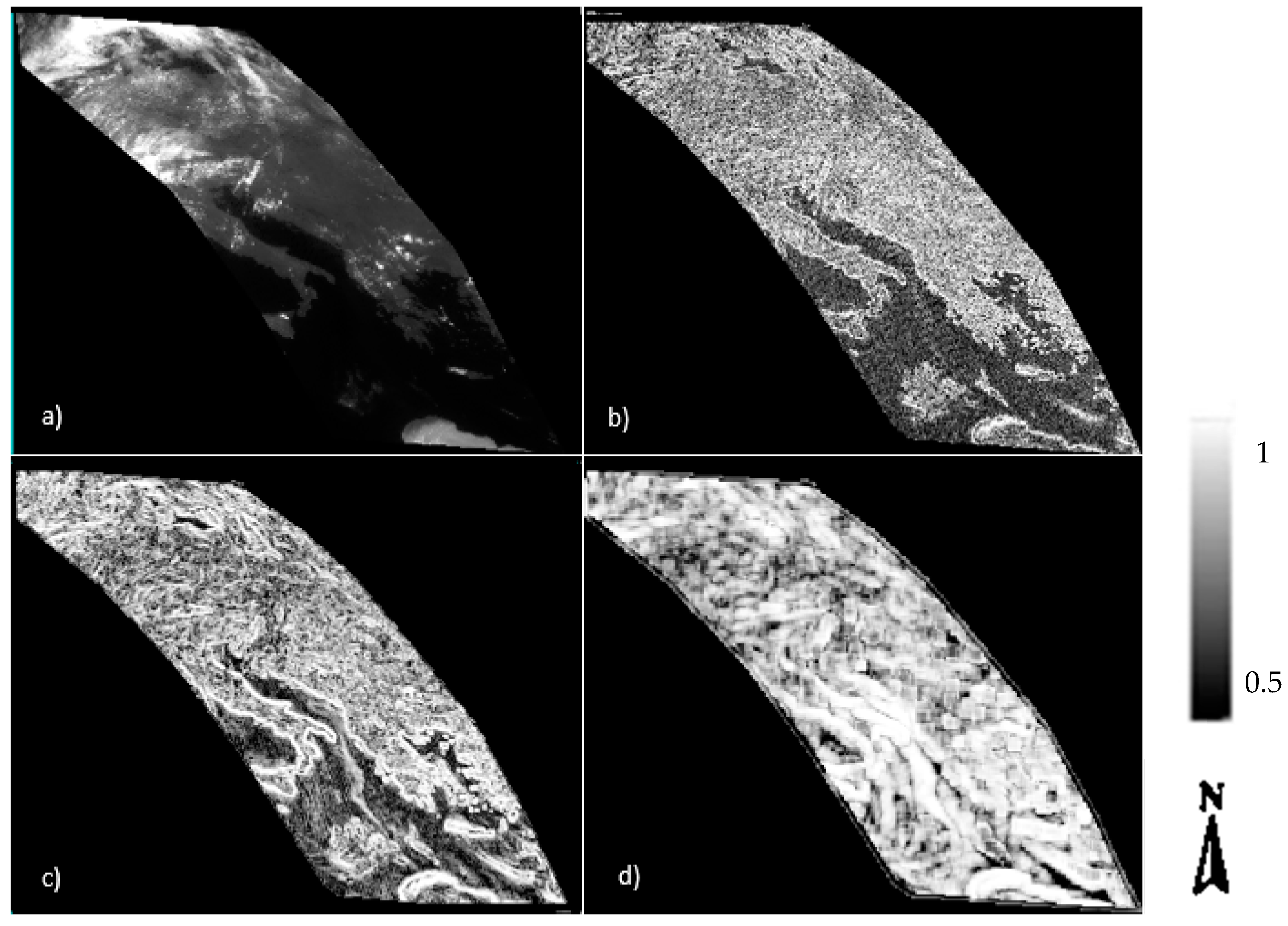
In order to provide a single reference grid with a similar spatial resolution and projection, the Meteosat-8 (IODC) image was projected on the Meteosat-10 (longitude = 0° W) spatial grid. For this purpose, both linear and IWD resampling methods were investigated. Our experimental results showed that the linear resampling had more interpolation artefacts in comparison to IWD. Due to the fact that a lesser number of artefacts leads to better image matching, an IWD interpolation technique was used in this study as the main resampling approach. Though, IWD resampling required a much longer processing time in comparison to the linear and bilinear resampling methods.
In order to control the location accuracy of the images, after this projection, all coastlines, whereby the height difference is zero, were aligned in both images. Consequently, if an object has a height, its location must be changed in the reference grid, in proportion to its height. Figure 8a shows the re-projected Meteosat-8 (IODC) image on the Meteosat-10 reference grid.

4.2. Image Matching and Co-Registration Outputs

The main objective of this step was the determination of tie points in between stereo pairs based on an automatic image matching technique. The image matching approach applied in this research is similar to the one used by Zakšek (2013) [19] and Merrucci (2016) [28]. As mentioned before, in this study, the image correlation was estimated at different levels of the image pyramid to better determine the tie points. At the upper levels of the pyramid, the spatial resolution varies proportionally to the selected coefficient in that level. In this study (referring to [21]), coefficient 3 was used. Thus, the value of the image shift and correlation index (CI) was computed for all the pyramid levels, and if the correlation index value at the end of the pyramid (with the least spatial resolution) was less than 0.7, then the calculated shift value was considered as unreliable and zero was used instead (see [14]).
In this study, due to the good results obtained in [19,28], the dimensions of the moving and search windows were selected respectively by 7 × 7 and 13 × 13. Figure 8b–d shows the correlation index in different levels of the pyramid. The brighter the image pixel in this figure, the higher the correlation index.
As a result of image matching, the amount of shift between image pairs was also generally estimated and tie points were selected based on the highest correlation in between the image pairs. Finally, the resulting output from this step was a file with in which image coordinate pairs like ( x S E V I R I 1 , y S E V I R I 1 , x I O D C , y I O D C ) for the entire tie points are presented. As a result, 2,102,398 tie points were generated automatically between the stereo pairs.
Since the accuracy of height estimation is directly influenced by the image matching results, it is necessary to examine the relative co-registration of the stereo pairs after doing the registration. A visual tool for fast quality control is the application of a color composite in a Red, Green and Blue (RGB) space. The first SEVIRI was chosen as the red and green bands, and SEVIRI-IODC for the blue band. Figure 9 shows such a color composite. As is clear from this figure, all the coastlines are overlaid on top of each other in all images. It can also be seen in the magnified red polygon that the clouds are more detectable with the existing parallax in the images in comparison to each of the single gray-scale channels.
After tie point generation and ensuring the accuracy of the results, it is possible to form the 3D linear equation (Equation (3)) to estimate the amount of parallax between the image pairs and finally cloud height. Hence, in the following subsection, the results of solving the equations in Section 3.3.4 (intersection) are given. In addition, some of the mid-level outputs of the cross-correlation analysis in different image pyramid levels are provided as Supplementary Materials (see Figures S1–S6 in SM-5).

4.3. Parallax Estimation (Intersection)

As it was mentioned in Section 3.3.4, after the image matching, tie point selection, and coordinate system conversion, the intersection equation (Equation (3)) was solved for the stereo pairs. As a result, two parameters, including the value and minimum intersection distance, were estimated. 
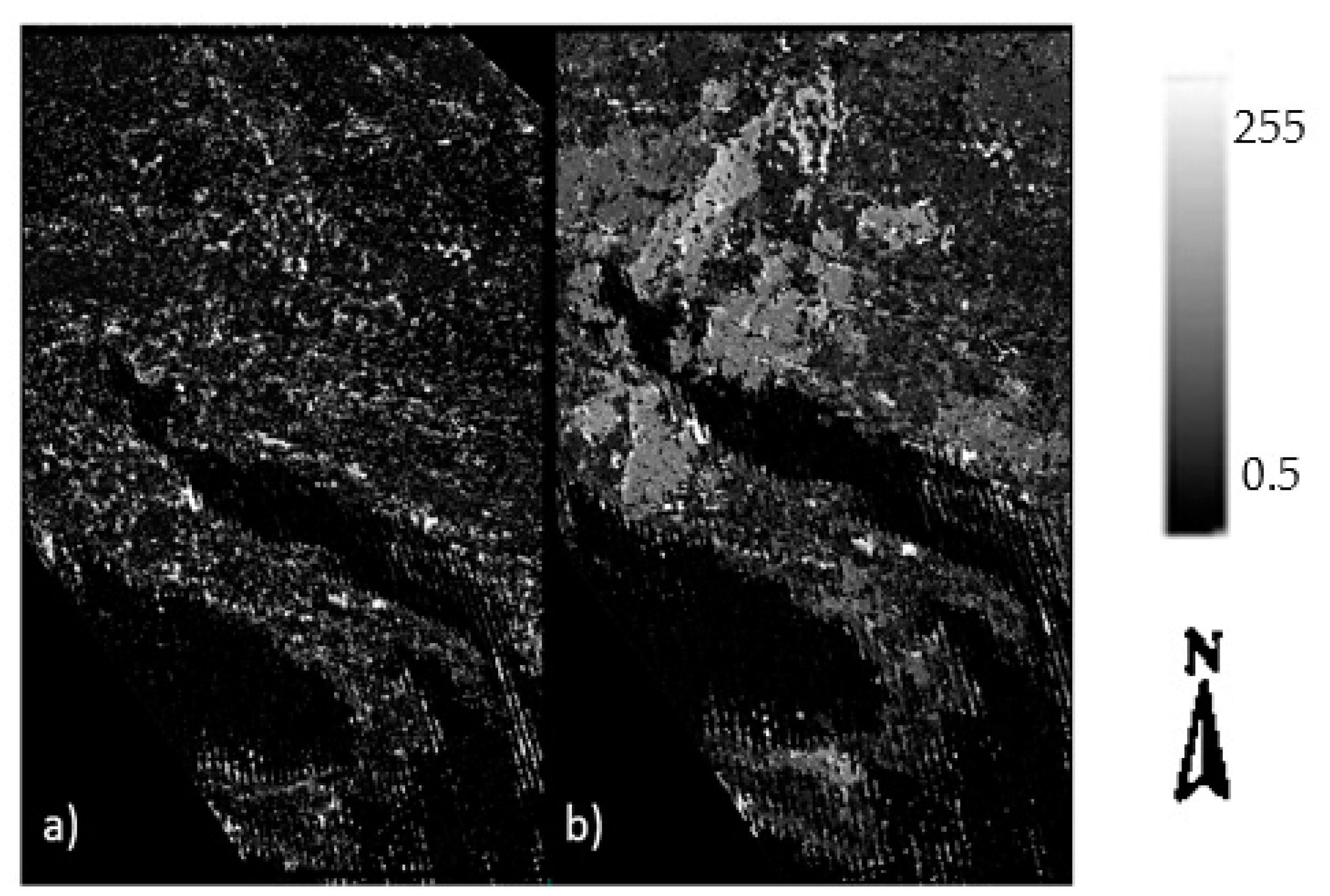
Figure 10 represents both the estimated parallax value and minimum intersection distance in our study area.
The distance between the epipolar lines in the epipolar geometry (d), i.e., the minimum intersection distance, indicates the accuracy of the height estimation. Given that d is a measure of intersection uncertainty, it should be as small as possible. The less the distance, the darker the corresponding pixels of Figure 10a, and the more precise the resulting output.
The parallax results are different in that the higher the parallax value, the higher the probability of having cloudy pixels. Therefore, in Figure 10b, the brighter the pixels, the higher the parallax in between the stereo pairs [60].

4.4. Results of the Proposed Detection Method Based on the P-d Feature Space

Looking at 
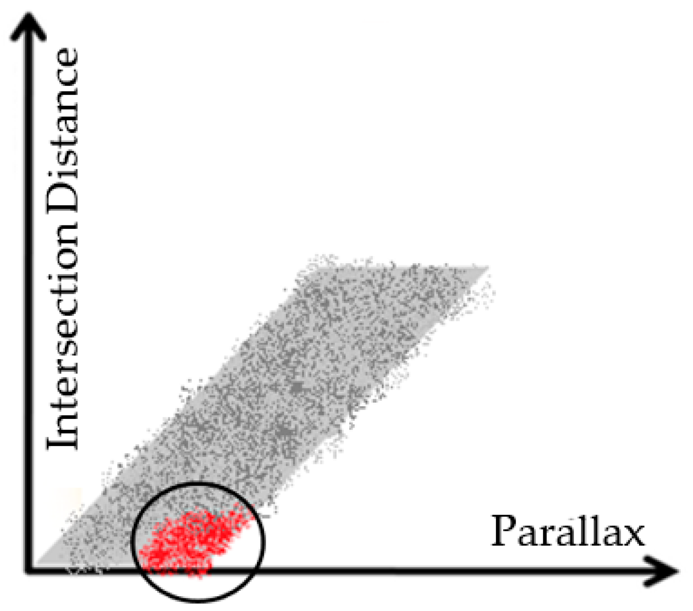
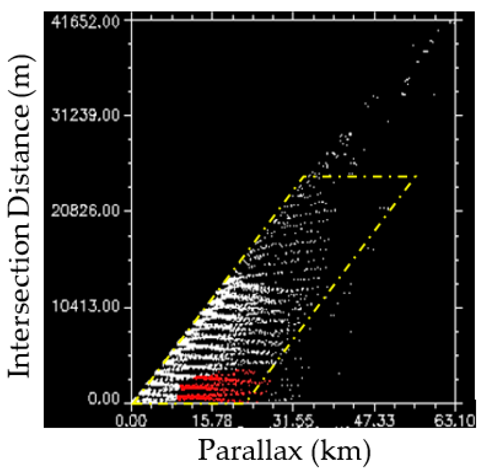
Figure 10b, it is clear that the cloudy pixels were determined quite well based only on their parallax shift. However, in order to more precisely detect the clouds from other pixels in the image, simultaneous use of the minimum intersection distance (d) and parallax (p) in a 2D scatterplot is proposed (Figure 11). The decision making for being a cloudy pixel is to minimize the former and maximize the latter (see Figure 6) in the 2D scatterplot. In 
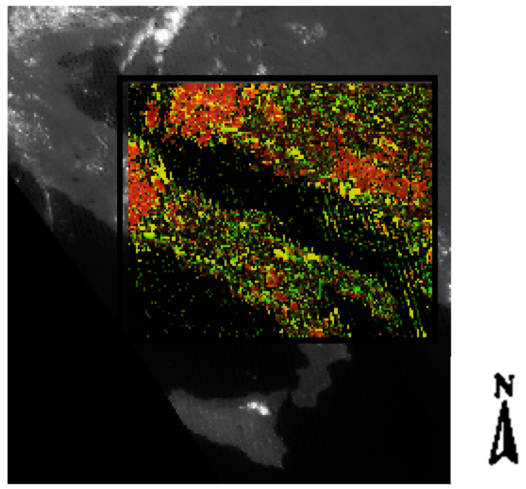
Figure 10, the red selected region, represents the cloudy pixels. The linked image subset with the scatter plot in Figure 11 is also shown in Figure 12. However, only one subset of the image is shown in Figure 12 for the sake of better visualization and comparison. As can be seen in Figure 12, and by comparing the results with Figure 9, the red region is completely concentrated on the cloudy pixels. Therefore, as a visual evaluation of the results, it seems that the model and the proposed feature space work perfectly for cloud detection purposes.
Although the visual evaluation of the results seems trustworthy and acceptable, nevertheless, for a better validation, the results of this detection were compared with three well-known target detection techniques in remote sensing, including CEM, MF, and ACE. In the following subsection, the results of this comparison and better validation of the results are presented.

4.5. Comparison with Other Target Detection Methods

In order to evaluate the results of the proposed detection approach, three common target detection techniques, including ACE, CEM, and MF, were implemented on the Meteosat multispectral images. The color composite of the visible and near infrared spectral bands (VIS: 0.8, VIS: 0.6, IR: 8.7 μm) is shown in Figure 2.
After introducing the multispectral image in 
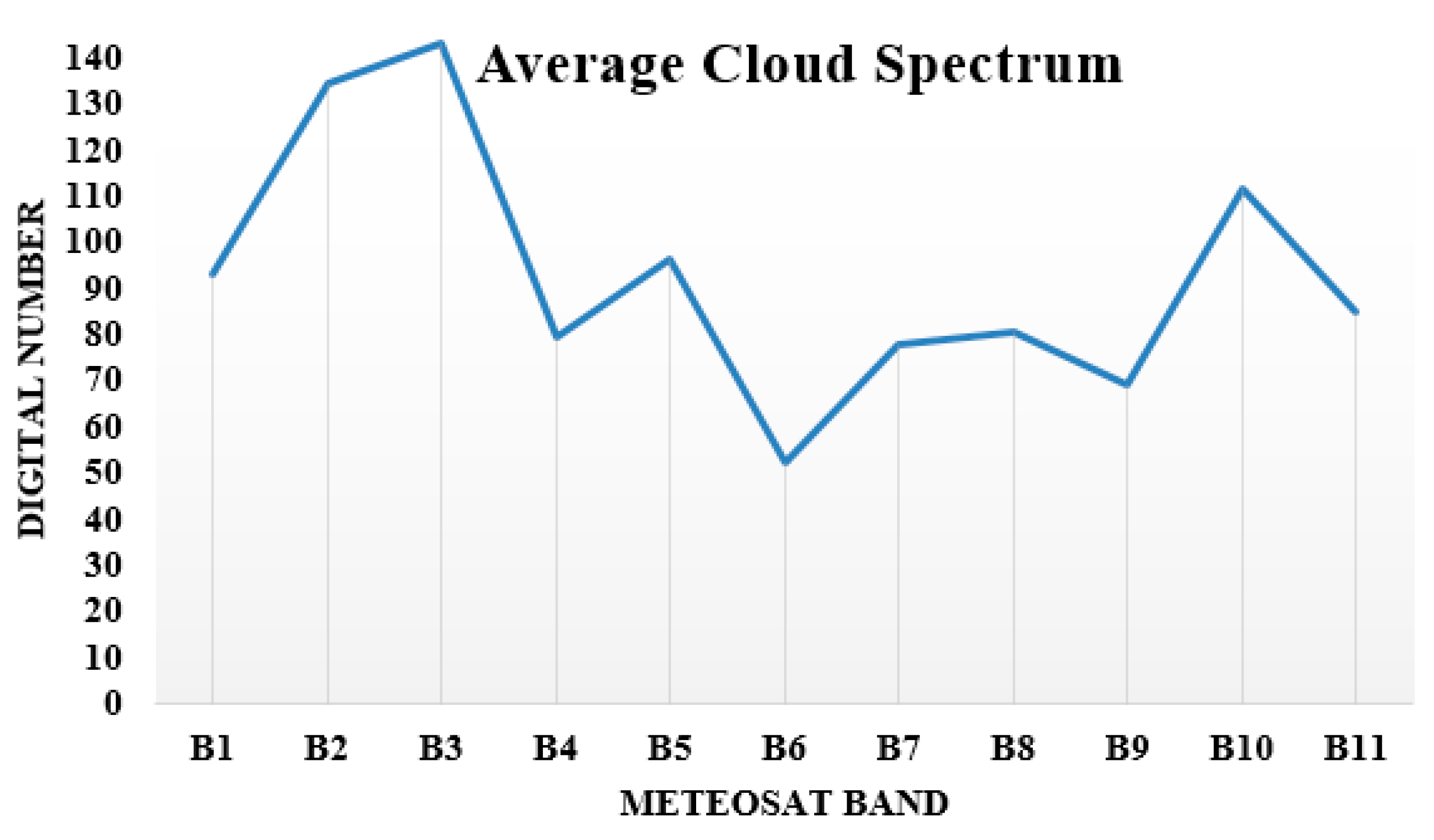
Figure 2 and selecting the ROIs manually (from two specific cloud and no-cloud targets), the three above-mentioned detection algorithms were implemented. For this purpose, the average cloud spectrum based on the selected ROIs in cloudy regions was first produced. The mean cloud signal obtained from the selected cloudy ROIs is shown in Figure 13. This spectrum is used as training spectra, which will be used as input in the detection models. By the way, it should be mentioned that a minimum noise fraction (MNF) transform [67] was also implemented on the raw multispectral image to reduce the spectral noise. Afterwards, the set of detection algorithms were performed respectively on the images. 
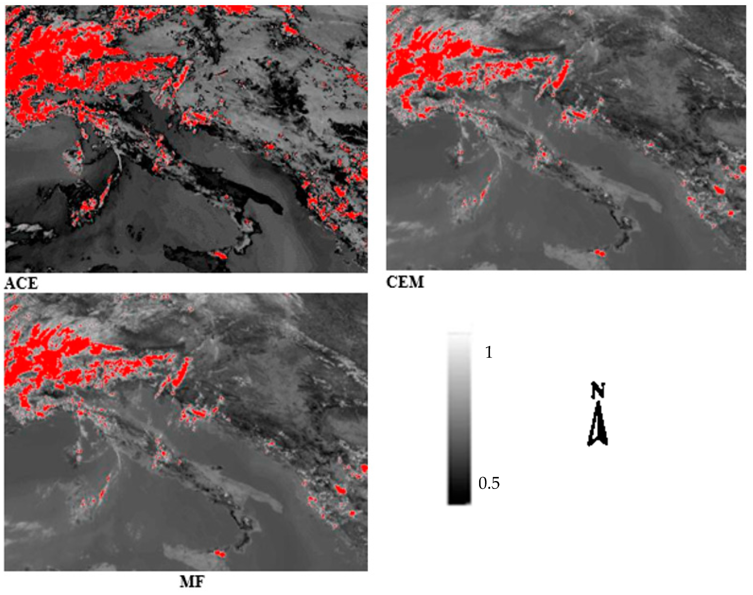
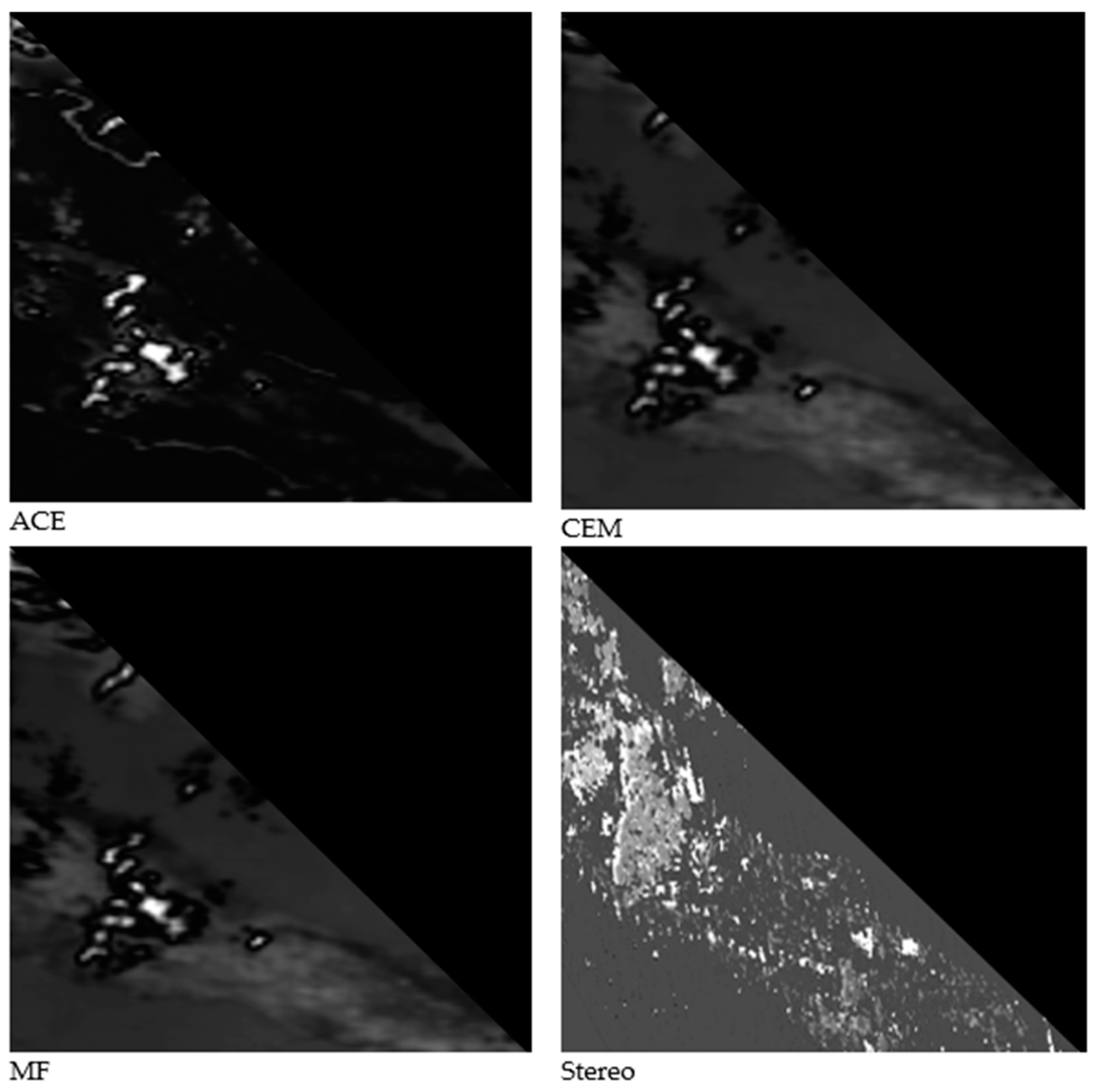
Figure 14 represents the resulting detection outputs from these algorithms in a smaller subset of our study area.
As is clear from Figure 14, the three mentioned algorithms worked well for the detection of clouds with specific detection probability thresholds of 0.70. The output probability maps and detection results from the MF and CEM methods are quite similar to each other.
In Figure 14, the brighter the pixels, the higher the probability of detection, which is normalized here to 255 because of the better visualization. The detection results are only visually comparable in 
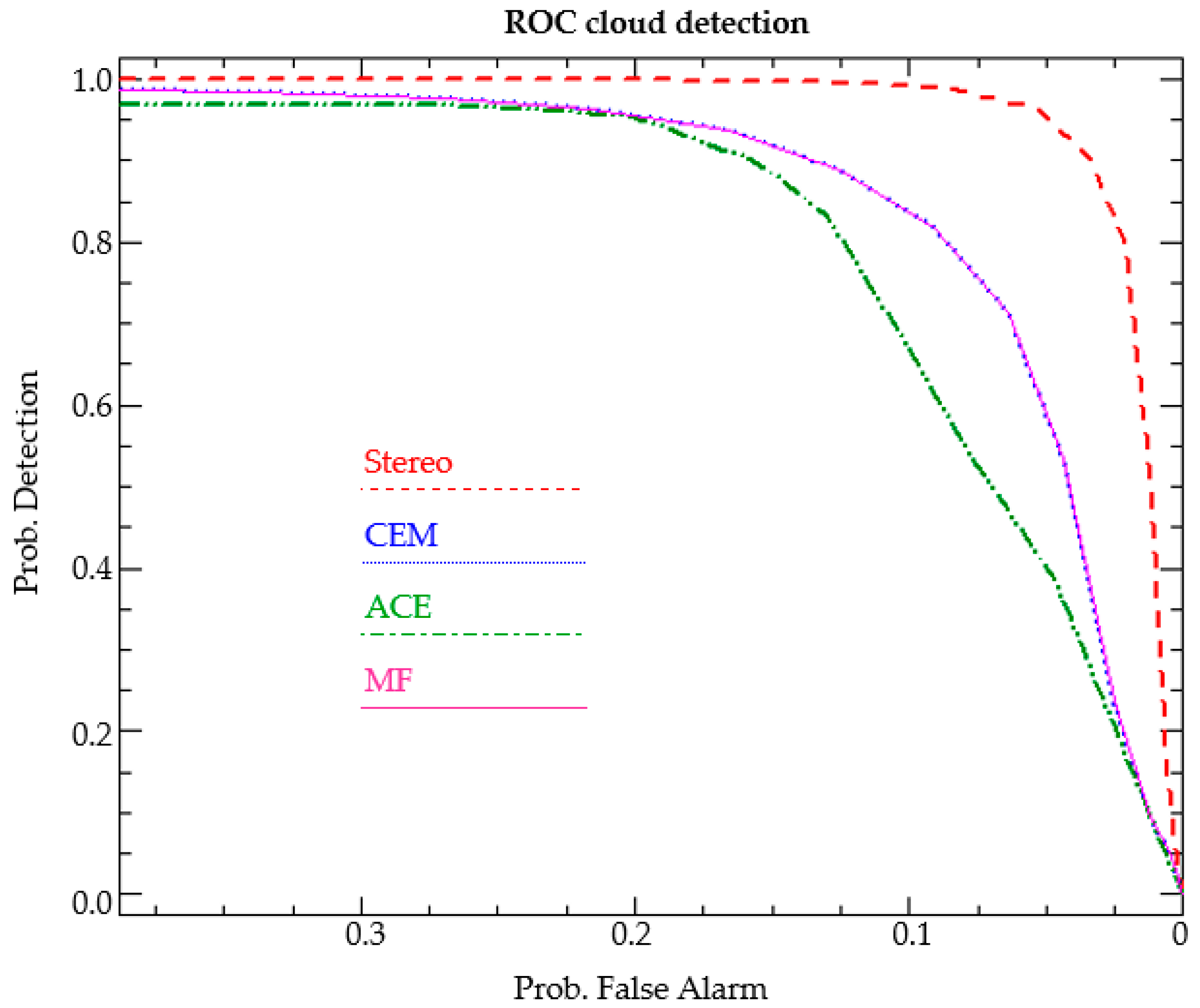
Figure 14. Hence, for the sake of a better performance comparison, the conventional receiver operating characteristic (ROC) curve [47] was used (see Figure 15).
After having a precise look at the curves shown in Figure 15, it is clear that the detection performance was similar in both the CEM and MF methods while the ACE method had a weaker performance. This comparison suggests a better detection power for the proposed method. As is clear from Figure 14, some low-density clouds were not clearly detected using the common target detection techniques.
In addition, in order to provide a quantitative comparison of the results, an area under the curve (AUC) criteria was also calculated for the methods. AUC stands for the area under the ROC curve. This criterion measures the entire two-dimensional area underneath the entire ROC curve (think integral calculus) from (0, 0) to (1, 1). The AUC value lies between 0.5 to 1, where 0.5 denotes a bad classifier and 1 denotes an excellent classifier [47].
Table 1 shows the calculated AUC values for the different methods. The interesting result is that both the MF and CEM methods had similar AUC values. Although, the ACE method detected the clouds not very badly, but it was the weakest method in this study for the detection of clouds. Finally, as is clear from Table 1, the best detection performance was for the stereo-based approach, with AUC = 0.93.
A general look at the current results suggests that although the common spectral-based target detection techniques have recognized cloudy pixels well in most areas, these techniques did not work very well in very mixed pixels and for small or quite transparent clouds. These kinds of clouds were better detected in the proposed stereo-based approach. Nevertheless, Figure 12 shows more noisy outputs in the proposed method. Although, because of the application of the HRV band in the proposed approach, the corresponding detection results originally have a better spatial resolution in comparison to the other detection methods.
In addition, according to the fact that the ROC analysis did not take into account local variability within the results, the so-called local Moran’s I index [68] as a local spatial statistic was also applied. This index is available in the ENVI toolboxes. The local Moran’s I index identifies pixel clustering. Positive values indicate a cluster of similar values while negative values imply no clustering (that is, high variability between neighboring pixels). ENVI uses the Anselin method [68] for the Moran’s I index by computing a row-standardized spatial weights matrix and standardized variables (see https://www.harrisgeospatial.com/docs/LocalSpatialStatistics.html for more details). Figure 16 presents the result of this analysis on a small image subset from all detection methods.
From Figure 16, which shows only a small part of the image, it seems that the entire detection methods showed less variability near the clouds. However, it seems that near the borders of clouds, there are more variabilities for both MF and CEM, and less variabilities respectively for ACE and stereo.

4.6. Other Characteristics of the P–d Space

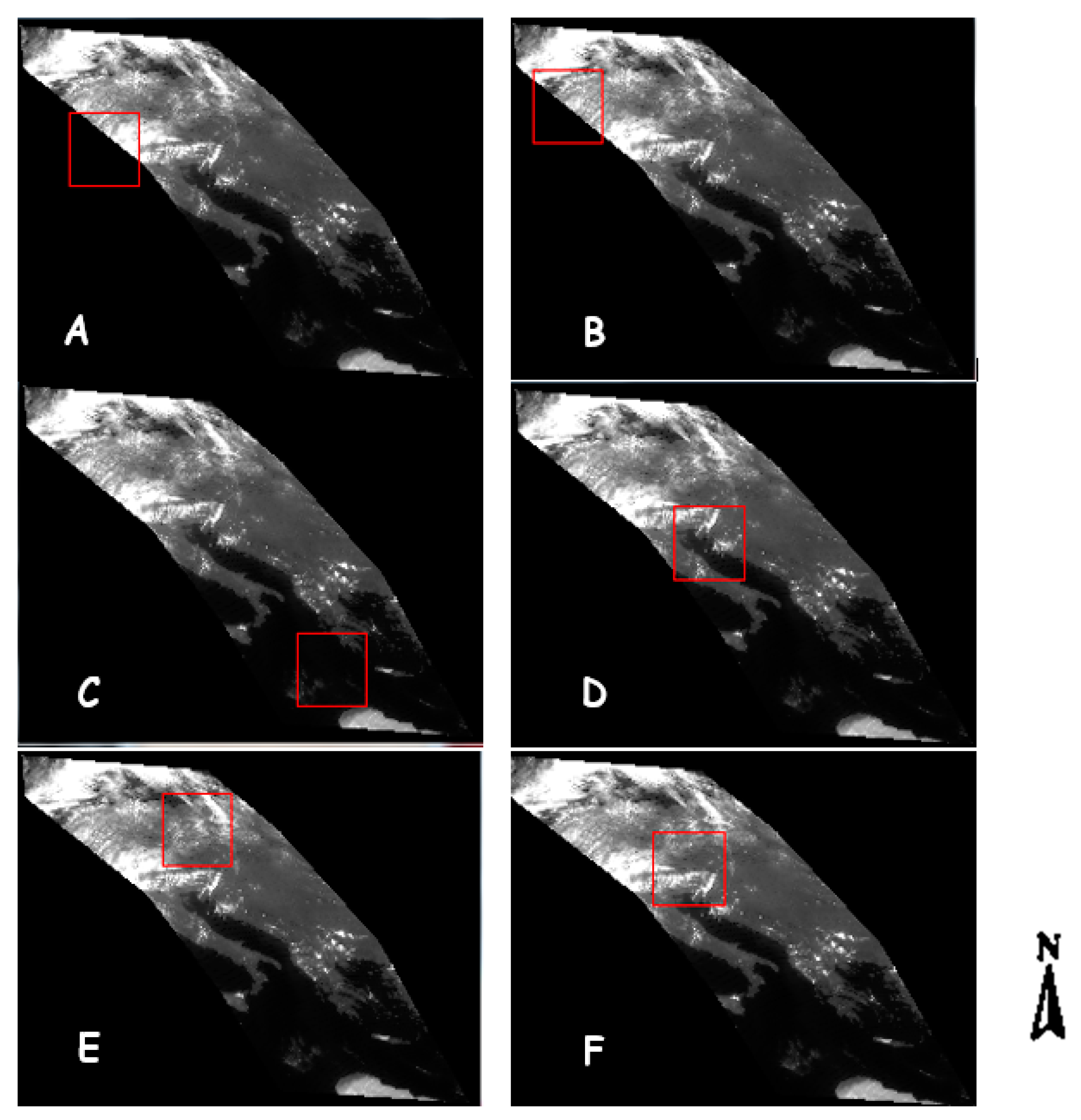
Our experience with different image subsets showed that the characteristics of the represented parallelogram in the 2D feature space is changing in different regions based on the amount of cloud cover and probably the cloud type. For better clarification of the changing characteristics of the resulting parallelogram space, we provide the P–d scatter plots in different subsets of the entire image. These subsets and their corresponding P–d scatter plot are respectively shown in Figure 17 and Figure 18.
In Figure 17, we tried to select and analyze the image subsets in regions with different amounts of cloud cover.
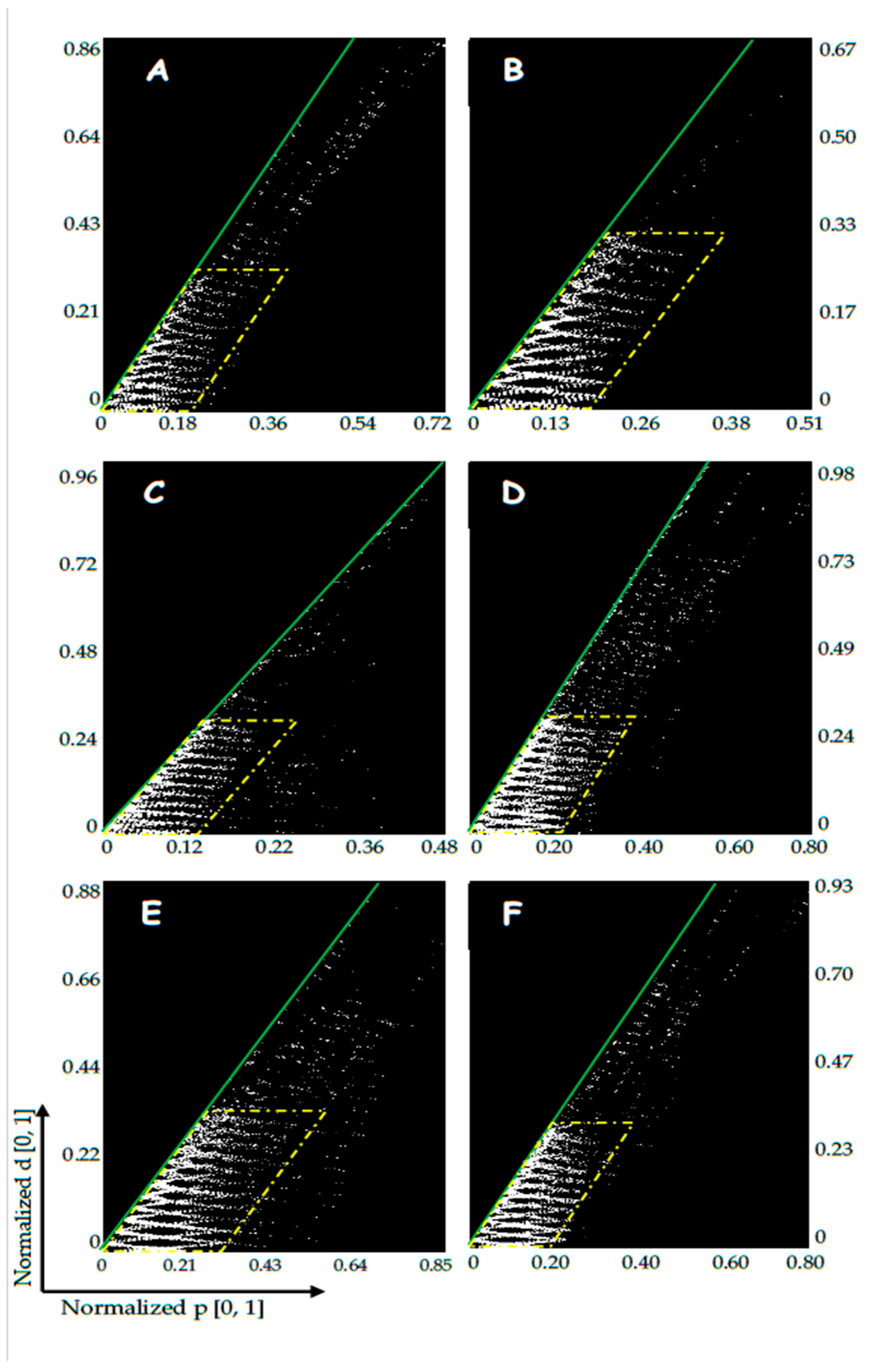
Afterwards, for each region, a suitable parallelogram was fitted to the pixel points in the P–d feature space (yellow polygons in Figure 18). The red dashed line is drawn from the coordinate system origin point to the other end of the coordinate system. The green line is tangent to the points and shows the slope of the parallelogram in this space.
A visual comparison of the graphs and images in Figure 17 and Figure 18 shows that the lower the amount of clouds in a region, the smaller the slope of the green line in Figure 18. For example, in Figure 17C, there is no cloud in the subset and as a result the green line has a higher slope angle to the x-axis.
Hence, the slope angle of the green lines can be introduced as a representative value, which shows the amount of cloud clover. In order to provide a better numerical comparison, the slope angle of the green line was calculated for all the graphs in Figure 18.
The results of the slope angle calculations, which are shown in Table 2, seem very interesting. As is clear, the lower the amount of cloud cover, the bigger the estimated slope angle. For example, in image subset C, the least amount of cloud cover exists, and it has the biggest slope angle in comparison to other subsets. The mentioned result was already expected, since the bigger slope angle corresponds to a smaller parallax value and bigger intersection distance.
A precise look at the normalized values of both the parallax and intersection distance in Figure 18 shows that these values are changing for each image subset. As it was also expected, the lower the amount of clouds in an image subset, the lower the maximum value of the parallax (see Figure 17C and Figure 18C). From the analysis on the different image subsets and their corresponding P–d space, we came to the conclusion that cloudy pixels have a parallax value bigger than P = 0.1. However, the intersection distance range does not generally change very much among the various image subsets. Nevertheless, the same threshold value (d = 0.1) for this parameter seems to also be applicable for the detection of cloudy pixels.
Nevertheless, it is worth mentioning that these values cannot be generalized to all other places, atmospheric conditions, and/or images or scenes. Hence, for a general threshold value suggestion, more research on different image scenes, various amounts of cloud cover, other geographical locations, daytime and seasons, etc. are required.
Another interesting behavior in this graph is the several semi-parabolic shapes, which are located on top of each other and their central point is tangential to the green line. These parabolas show the mathematical relation between the P and d, shown in Equation (5):
d = ( P 1 P 2 ) 2 ,
where P1 and P2 are respectively the parallax values for the first (left) and second (right) images in the stereo pair.
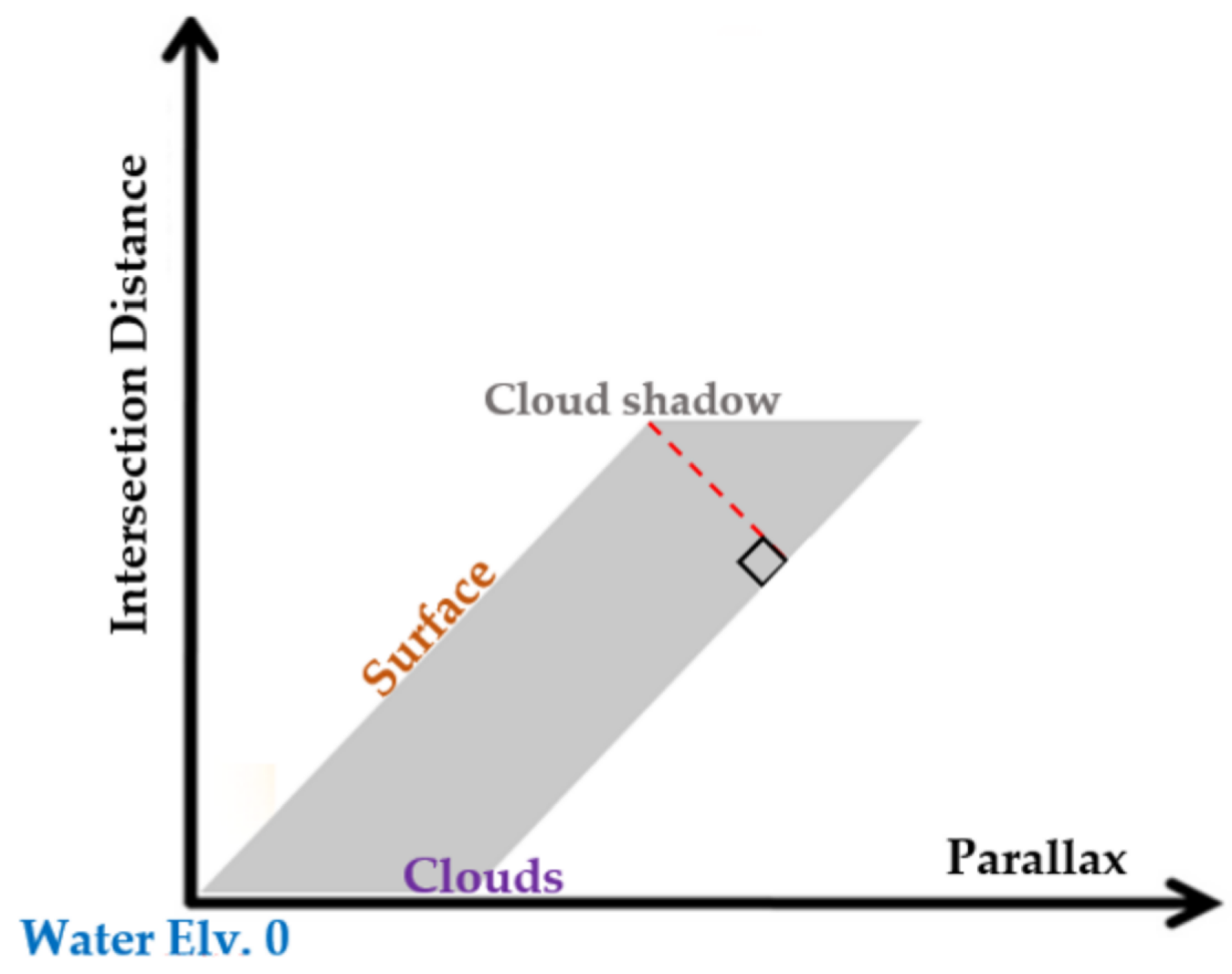
Our analysis on the graphs and image pixels also showed that the left side of the parallelogram that is tangent to the green line holds the elevation information of the ground objects. As can be seen, the base of the yellow parallelogram overlays on the x-axis and its slope shows the slope of the green line. Hence, this information shall be later used as a criteria/index to present the amount of cloud cover in an image. This information is summarized in Figure 19.
It is worth mentioning that we also checked the data points above the yellow parallelogram and the conclusion was that they mostly contained not very much information about clouds because the accuracy of estimation in those points are very low (d has big values).
In the next section, a brief discussion on the above-mentioned results is given.

5. Discussion

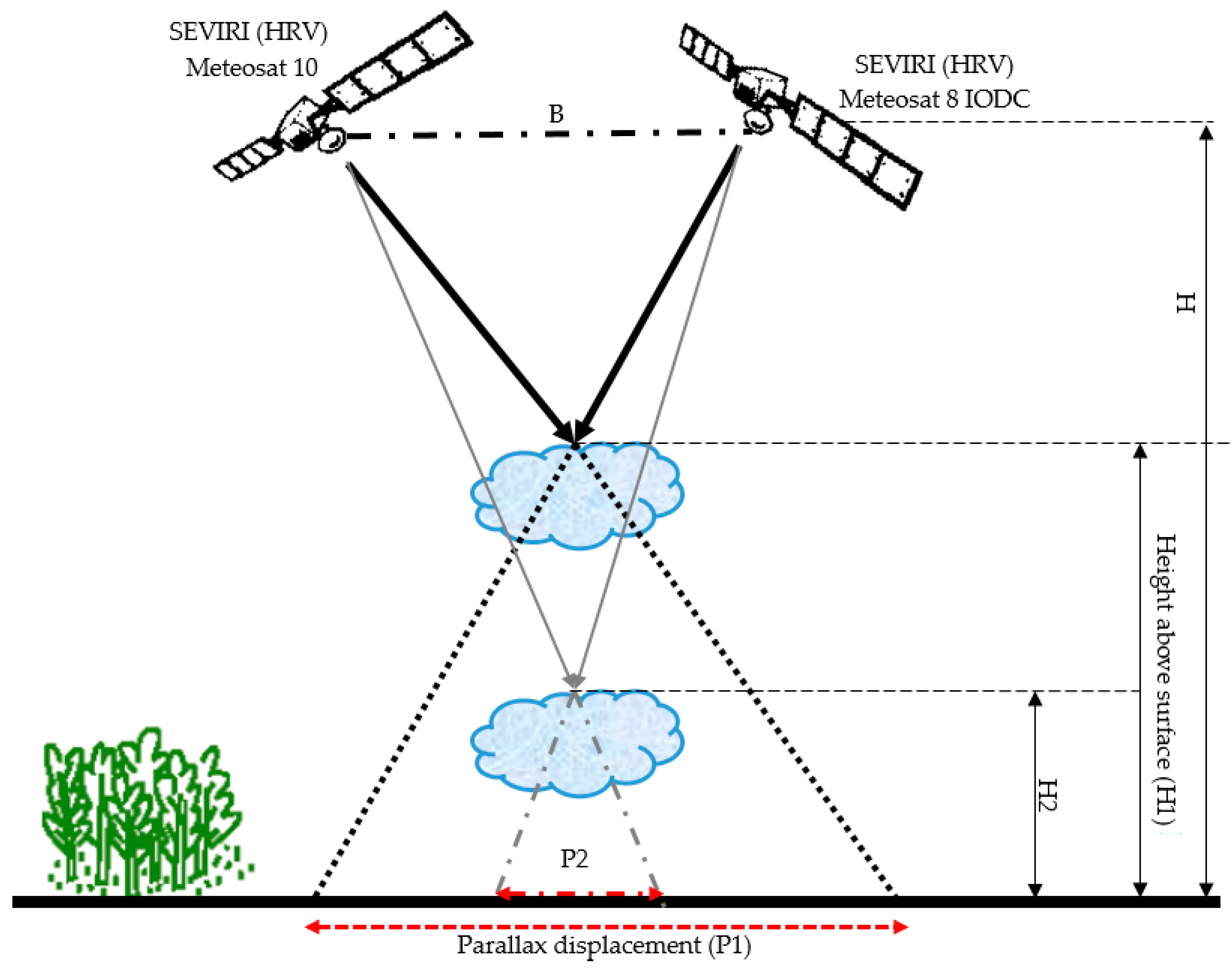
The image data used for this stereo analysis included the HRV bands from two identical SEVIRI sensors, which were on board two platforms in 0° W and 41.5° E geographical longitudes. We did not use the Rapid Scan Services (RSS) mode, because in this mode, the acquisition of the first sensor takes place at 9.5°E and as a result the spatial baseline, i.e., the distance between the two stereo pairs (parameter B in Figure 4), will decrease. As a consequence, the height estimation accuracy of the stereo model will also decrease. It is, however, worth mentioning that the lower spatial baseline may improve the image matching results, but because of the low time difference between the HRV pairs (i.e., 5 s), the matching was improved in this study. This 5 second time difference is because images from the second generation of Meteosat are taken every 15 minutes using a line by line scan basis. Therefore, we have a specific acquisition time for each image line and a time range for each picture. For example, in our data the start and end time of the image acquisition were 11:45:09–11:57:39 and 11:45:10–11:57:44 respectively for the Meteosat-10 and Meteosat-8 (IODC), which confirms the maximum 5 seconds time difference between the stereo pairs.
Since the accuracy of the height estimation depends on the so-called baseline-to-height ratio (B/H) [69], the higher the B/H value, the more precise the height estimation results. It should also be noted that this statement is true for the coarse resolution data—with the HRV bands (~ 1 km) that is still our case—but this statement might not be valid for higher resolution images because of the problem of image matching. As a consequence, it is clear that the longer baseline (in coarse resolution data like our data) results in a better accuracy.
From a general view of our research, there is a list of benefits to be mentioned: (1) The lower time difference between the stereo pairs (see Figure 1a,b); (2) the higher spatial baseline (higher B/H value, consequently higher height/parallax accuracy); (3) better spatial resolution because of the application of HRV bands. Thereupon, the differences in between images related to the cloud movements and other temporal changes is the smallest; and (4) both sensors have a similar radiometric resolution (10 bit), which makes the texture analysis much easier.
In this research, both image pairs were acquired by similar sensors with a comparable spectral/spatial response function. Therefore, higher quality of the tie point selection is expected in comparison to that of [28]. However, there are still some differences, like the solar illumination condition and viewing geometry, which makes one specific object in the overlapping region of image pairs appear differently in each. Thereupon, finding highly correlated tie points was more difficult. Hence, a Wallis filter was applied on the raw images to remove the effect of different illuminations. Nevertheless, according to the given definition of clouds in Section 1, there might still be difficulties in performing the image matching, especially when transparent clouds are located on top of very heterogeneous regions. This needs to be investigated with further research.
On the other hand, image texture might be a problem only if the spatial resolution of the input data is very fine or too coarse. Considering SEVIRI, meteorological clouds usually have enough structure (texture) in the HRV channel [28] for image matching.
In addition, one other main drawback of this method is also that the accuracy of the results is dependent on the positional accuracy of the input images. It is not particularly important for the absolute geolocation to be accurate, but the co-registration between the images from both satellites must fit perfectly. For this reason, it makes sense to check the co-registration accuracy during pre-processing when all datasets are transposed to the same coordinate system. This can be done automatically by adjusting the co-registration along coastlines.
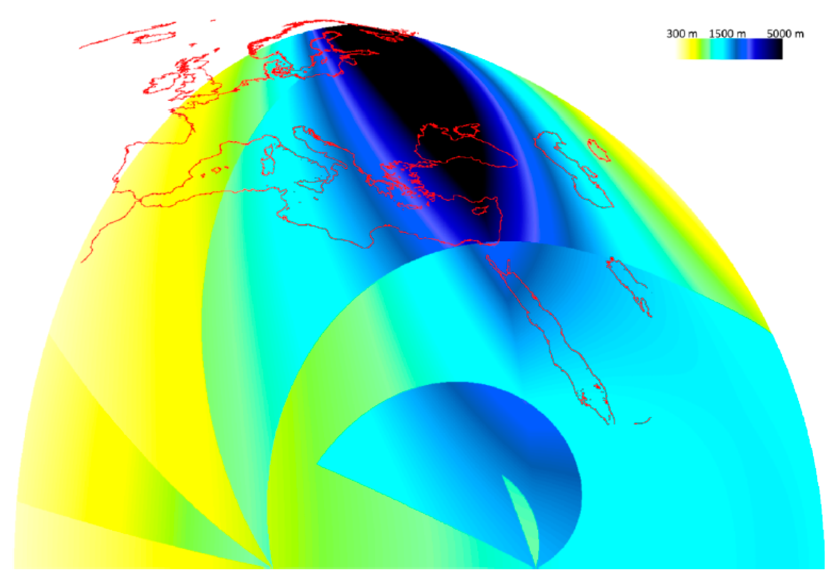
One potential source of inaccuracy in the results is that the spatial resolution of the Meteosat pixels reduces near their margin. It means the pixel size become bigger. Thus, it is expected that the spatial resolution of the IODC image in the overlapping part of the stereo pair is worse than 1 km (around 2–3 km), which will affect the accuracy of correlation in between both pairs, tie point determination, and finally, the height estimation accuracy. Nevertheless, in a stereo study by Merrucci et al. (2016) [28], an analysis on the accuracy of the results was performed. This analysis was performed assuming the spatial resolution of both stereo pairs was similar. In our study, we are much closer to this assumption in comparison to [28], because of the application of HRV bands from the similar sensor in both pairs. However, this investigation showed that the accuracy of estimation is between 150 and 2500 m and the minimum detectable cloud height is two-fold, i.e., varies in the range 300–5000 m. To see more details about how these investigations were performed, see [28], and Figure 20, which shows the resulting accuracy estimation from [28].
The other limitation to be mentioned is the re-gridding of the images and implementation of the the image matching analysis before their complete georeferencing. This may result in resampling artefacts and location inaccuracies, and consequently, automatic matching with a lower accuracy. Another option would have been to resolve the internal and external geometry of each image before parallax calculations. The first reason to do the gridding instead of geocoding is that we would like to test this method later for improving the down-welling solar irradiance (this is currently under study by the authors). In this case, the Meteosat-10 image will stay in its original grid without any radiometric changes, which is important for estimating down-welling solar irradiance. Therefore, we would like to keep the original grid of Meteosat-10 untouched, without any resampling. On the other hand, using the gridding method is a faster approach. Nevertheless, in order to overcome the above-mentioned limitations, first we used the IWD resampling with the least amount of resampling artefacts while gridding. On the other hand, to check the locational accuracy of the images, we aligned the images with the coastlines. This aligning method was previously used in [28] and was also successful.
From the numerous tests carried out in this study, it was found that image processing software, such as ENVI (Environment for Visualizing Images), PCI-Geomatica, ERDAS (Earth Resources Data Analysis Systems) Imagine, and LPS (Leica Photogrammetry Suit), were not able to estimate the correlation between the Meteosat image pairs and their tie points. Moreover, previous research in [28] also showed that even with the application of several scale and direction constraints, general categories of automatic image matching methods (including region-based and feature-based [70,71,72,73]) cannot provide sufficient numbers of highly correlated tie points in between Meteosat images. Therefore, in this study, we used a similar method to the one proposed by Zakšek, et al. (2013) in [19,28]. However, as mentioned before, the results of this image matching depends on the size of the search area and the moving window. For example, a large-sized window cannot detect smaller objects, but it can easily detect and extract larger objects and vice versa. Therefore, to optimize the matching results, the best approach was to try local-based image matching and correlation estimation in different levels of image pyramids.
After the image matching, tie point selection, and coordinate system conversion, the intersection equation (Equation (1)) was solved for the stereo pairs. As a result, two parameters, including the parallax value and minimum intersection distance, were estimated. Afterwards, in order to more precisely detect the clouds from other pixels in the image, simultaneous use of the minimum intersection distance (d) and parallax (p) in a 2D scatterplot was proposed.
The decision making for being a cloudy pixel was to minimize the former and maximize the latter (see Figure 7) in the 2D scatterplot. Comparison of the resulted ROC curve of the proposed detection approach with that of other common detection methods showed that the proposed approach had better results. However, it is worth mentioning that this comparison depends on the selection of two important threshold values: First, the selected threshold for common detection methods (which was in this study the probability value of 0.7); and second, the selected threshold/boundary for classifying cloudy pixels in the proposed 2D scatterplot P–d (equal to 0.1 in the normalized space). Nevertheless, it is worth mentioning that these values cannot be generalized to all other places, atmospheric conditions, and/or images or scenes. Hence, for a general threshold value suggestion, more research on different image scenes, various amounts of cloud cover, other geographical locations, daytime and seasons, etc. is required. Moreover, the detection results of the common methods also depend on the precision of the training ROI set. In addition, a local variability analysis of the results showed that variability near the cloudy pixels is less for the stereo, ACE, CEM, and MF methods.
In the proposed parallelogram space, various tests based on different image subsets were performed. These analyses showed that the parallelogram includes some information about clouds. However, the definition of specified indices and better characterization of this space requires more experimental research, which is currently under more study and investigation by the authors, to ensure the reproducibility of the results.
Generally speaking, the applied stereo approach has been under development for years, simultaneously with the development of new constellations of meteorological geostationary satellites. Therefore, we expect a continuous growing exploitation of this technique in the remote sensing society and specifically weather satellite research.

6. Conclusions

In this study, a new method for cloud detection based on a stereography technique and the cloud height/parallax information was studied. The applied stereography technique is one of the most prominent methods available to estimate height information for cloud, and has its own advantages and disadvantages. The most important characteristics, weaknesses, and strengths of the method used in this study are discussed in [28]. In order to achieve the highest possible accuracy of the results from this technique, we used the highest available spatial resolution of the Meteosat images using their HRV bands in both pairs. On the other hand, with the low time difference between image pairs (i.e., less than 5 s), the cloud motion error was also negligible.
One of the weaknesses of the stereo model might be in the very highly uniform clouds, whereby the image matching has a higher probability of failing. However, it is worth mentioning that the cloud structure is only problematic when the spatial resolution of the input image pairs is very low (lower than 5000 m) [19,28]. Nevertheless, since this method has benefited from the visible band of the sensor, it is limited to measurements at daylight hours. However, continuous development in geostationary sensors allows the use of all the advantages mentioned in this research to provide effective monitoring of clouds on a global scale, with different imaging bands, as well during both night and day.
Our recommendation for further research is as follows: (1) To test the stereo-based detection method on the other spectral bands, because other spectral bands can provide complementary information for analysis of the clouds; (2) to analyze the proposed 2D scatter plot to extract further information from the clouds, which is only based on their geometry. Further studies on this space shall provide the possibility to discriminate the cloud types and height based on the index definition; and (3) another recommendation that is currently under study by us is the improvement of cloud determination models like APOLLO [70,71] with the application of stereo analysis.

Supplementary Materials

The following are available online at https://www.mdpi.com/2072-4292/12/3/371/s1. Routine S1: IDL routine for reading HDF5 SEVIRI image data and its conversion to TIFF, Routine S2: The routine for reading image metadata, Routine S3: An IDL routine for preprocessing of the images with so-called Wallis filter, Routine S4: The introduction to input and outputs of a geolocation IDL file, Figure S1: the mid-level outputs from the cross correlation analysis in three image pyramid levels which was used for image matching.

Author Contributions

Conceptualization, S.D. and Y.M.; methodology, S.D., K.Z.; software, K.Z., V.S., S.D.; validation, S.D. and Y.M.; formal analysis, S.D. and Y.M.; investigation, S.D.; resources, S.D.; data curation, S.D., Y.M., K.Z.; writing—original draft preparation, S.D. And Y.M.; writing—review and editing, All; visualization, S.D.; supervision, Y.M., M.J.V.Z., G.S.; funding acquisition, G.S., K.Z. and S.D. All authors have read and agreed to the published version of the manuscript.

Funding

The publication of this article was funded by the Open Access Fund of Leibniz Universität Hannover.

Acknowledgments

We acknowledge EUMETSAT for the provision of SEVIRI data via EUMETCast. We also would like to thank Heipke (from Leibniz University of Hannover) for his comments and personal discussion with him, and Mirzade (from Shanghai University of China) for his help during testing some routines. We say thanks to the Technische Informations Bibliothek (TIB), the central library of Leibniz University, since the publication of this article was funded by the Open Access Fund of Leibniz Universität Hannover. We also greatly appreciate the reviewers for their complimentary comments and suggestions, which allowed us to greatly improve the quality of this research article.

Conflicts of Interest

The authors declare no conflict of interest.

Appendix A

The formula used for the correlation index estimation is like Equation (A1), where (C, L) is the image coordinate for a specific pixel, nC1 and nL1 are respectively the number of columns and lines for the searching (moving) window in the first stereo (right) image, and nC2 and nL2 are the number of columns and lines for the comparable moving window in the second stereo (left) image. (i, j), shows the coordinate of the pixel in each moving window, D N m i , j and D N r i , j are the gray-scale value for the left and right moving window, respectively, and finally, μ r and μ s are the mean gray-scale values for the right and left moving windows. For more details about the definition of these parameters and how the correlation index (CI) is defined and estimated, see [19]:
C I = i = 1 n C 1 2 , j = 1 n L 1 2 i = n C 1 2 1 , j = n L 1 2 1 ( D N r i , j μ r ) · ( D N m i , j μ s ) i = 1 n C 1 2 , j = 1 n L 1 2 i = n C 1 2 1 , j = n L 1 2 1 ( D N r i , j μ r ) 2 · i = 1 n C 1 2 , j = 1 n L 1 2 i = n C 1 2 1 , j = n L 1 2 1 ( D N m i , j μ s ) 2

Appendix B

In order to implement the stereography technique on a pair of images, the application of a set of conversions in between different coordinate systems is mandatory (Figure 6). These conversions are discussed in detail in Section 3.3.3 and the required mathematical equations for this purpose were presented. To this end, using Equation (1), the column and line vector (c, l), for each pixel were calculated in conversion #1. In the next step, i.e., conversion #2, (c, l) values should be converted to the geographic coordinates ( λ , φ ) according to the MSG geolocation data and a set of required mathematical equations. These equations are presented here (Equations (A2)–(A11)). Before that, using Equation (1), the values for x and y shall be given in degrees, which will then have to be converted to radians. After that, using the following set of equations (Equations (A2)–(A11)), conversion #2 shall be implemented [60]:
q 2 = ( r e q r p o l ) 2 ,
D 2 = d v 2 r e q 2 .
The numeric values are q = 1.006803 and D 2 = 1737121856 :
S D = ( d v   c o s   x   c o s   y ) 2 ( c o s 2 y + q 2 s i n 2 y ) D ,
s n = d v   c o s x cos y S D c o s 2 y + q 2 s i n 2 y ,
s 1 = d v s n cos x cos y ,
s 2 = s n sin x cos y ,
s 3 = s n sin y
s x y = s 1 2 + s 2 2 ,
λ = arctan ( s 2 s 1 ) + s u b _ l o n ,
φ = arctan ( q 2 s 3 s x y ) .
In which, sub_lon is defined as the longitude of the geostationary satellite (in the case of Meteosat-10, this is 0°, and in the case of Meteosat-8 IODC, this is 41.5°). In addition, the length of the two axes of the ellipsoid is assumed to be in accordance with the WGS84 model: The equatorial radius (req) is 6378.1370 km, whereas the polar radius (rpol) is assumed to be 6356.7523 km. The distance, dv, of the geostationary satellite is determined in accordance with Kepler’s third law as 42,142.5833 km. This distance may vary slightly as the orbit is not a perfect circle and orbit corrections are made on a regular basis [60]. In these equations, φ is the latitude, λ is the longitude, h is the height above the ellipsoid, and parameter N is defined using Equation (2) in Section 3.3.3.
Finally, the mentioned equations in conversion #3 will be applied to convert the estimated geographic coordinates into global geocentric Cartesian coordinates (X, Y, Z).

References

  1. NASA. The Importance of Understanding Clouds. National Aeronautics and Space Administration, 2005. Available online: https://www.nasa.gov/pdf/135641main_clouds_trifold21.pdf (accessed on 19 January 2020).
  2. Mobasheri, M.R.; FarajzadeAsl, M.; Karimi, N. A Fast Method for Determining the Cloud Top Pressure in Modis Photos (Fast CTP) in MODIS Images. Geogr. Dev. Iran. J. 2013, 11, 165–182. [Google Scholar] [CrossRef]
  3. Zi, Y.; Xie, F.; Jiang, Z. A Cloud Detection Method for Landsat 8 Images Based on PCANet. Remote Sens. 2018, 10, 877. [Google Scholar] [CrossRef] [Green Version]
  4. Escrig, H.; Batlles, F.J.; Alonso, J.; Baena, F.M.; Bosch, J.L.; Salbidegoitia, I.B.; Burgaleta, J.I. Cloud detection, classification and motion estimation using geostationary satellite imagery for cloud cover forecast. Energy 2013, 55, 853–859. [Google Scholar] [CrossRef]
  5. Geethu Chandran, A.J.; Jojy, C. A Survey of Cloud Detection Techniques For Satellite Images. Int. Res. J. Eng. Technol. (IRJET) 2015, 2. [Google Scholar]
  6. Wu, T.; Hu, X.; Zhang, Y.; Zhang, L.; Tao, P.; Lu, L. Automatic cloud detection for high resolution satellite stereo images and its application in terrain extraction. ISPRS J. Photogramm. Remote Sens. 2016, 121, 143–156. [Google Scholar] [CrossRef]
  7. Broadwater, J.; Chellappa, R. Hybrid Detectors for Subpixel Targets. Pattern Anal. Mach. Intell. IEEE Trans. 2007, 29, 1891–1903. [Google Scholar] [CrossRef]
  8. Chan, J.C.-W.; Canters, F. Ensemble classifiers for hyperspectral classification. In Proceedings of the Proceedings 5th EARSeL Workshop on Imaging Spectroscopy, Bruges, Belgium, 23–25 April 2007. [Google Scholar]
  9. Chang, C.I. Hyperspectral Imaging: Techniques for Spectral Detection and Classification; Wiley Publication: Hoboken, NJ, USA, 2003. [Google Scholar]
  10. Chang, C.I.; Heinz, D.C. Constrained subpixel target detection for remotely sensed imagery. IEEE Trans. Geosci. Remote Sens. 2000, 38, 1144–1158. [Google Scholar] [CrossRef] [Green Version]
  11. Gao, G.; Shi, G.; Yang, L.; Zhou, S. Moving Target Detection Based on the Spreading Characteristics of SAR Interferograms in the Magnitude-Phase Plane. Remote Sens. 2015, 7, 1836–1854. [Google Scholar] [CrossRef] [Green Version]
  12. Genkova, I.; Seiz, G.; Zuidema, P.; Zhao, G.; Di Girolamo, L. Cloud top height comparisons from ASTER, MISR, and MODIS for trade wind cumuli. Remote Sens. Environ. 2007, 107, 211–222. [Google Scholar] [CrossRef]
  13. Winker, D.M.; Pelon, J.; Coakley, J.A., Jr.; Ackerman, S.A.; Charlson, R.J.; Colarco, P.R.; Flamant, P.; Fu, Q.; Hoff, R.M.; Kittaka, C.; et al. The CALIPSO Mission. Bull. Am. Meteorol. Soc. 2010, 91, 1211–1230. [Google Scholar] [CrossRef]
  14. Winker, D.M.; Vaughan, M.A.; Omar, A.; Hu, Y.; Powell, K.A.; Liu, Z.; Hunt, W.H.; Young, S.A. Overview of the CALIPSO Mission and CALIOP Data Processing Algorithms. J. Atmos. Ocean. Technol. 2009, 26, 2310–2323. [Google Scholar] [CrossRef]
  15. Dubuisson, P.; Frouin, R.; Dessailly, D.; Duforêt, L.; Léon, J.-F.; Voss, K.; Antoine, D. Estimating the altitude of aerosol plumes over the ocean from reflectance ratio measurements in the O2 A-band. Remote Sens. Environ. 2009, 113, 1899–1911. [Google Scholar] [CrossRef]
  16. Chang, F.-L.; Minnis, P.; Lin, B.; Khaiyer, M.M.; Palikonda, R.; Spangenberg, D.A. A modified method for inferring upper troposphere cloud top height using the GOES 12 imager 10.7 and 13.3 μm data. J. Geophys. Res. Atmos. 2010, 115. [Google Scholar] [CrossRef] [Green Version]
  17. Richards, M.; Ackerman, S.; Pavolonis, M.; Feltz, W. Volcanic ash cloud heights using the MODIS CO2-slicing algorithm; University of Wisconsin-Madison: Madison, WI, USA, 2006. [Google Scholar]
  18. Oppenheimer, C. Review article: Volcanological applications of meteorological satellites. Int. J. Remote Sens. 1998, 19, 2829–2864. [Google Scholar] [CrossRef]
  19. Zakšek, K.; Hort, M.; Zaletelj, J.; Langmann, B. Monitoring volcanic ash cloud top height through simultaneous retrieval of optical data from polar orbiting and geostationary satellites. Atmos. Chem. Phys. 2013, 2589–2606. [Google Scholar] [CrossRef] [Green Version]
  20. Glaze, L.S.; Francis, P.W.; Self, S.; Rothery, D.A. The 16 September 1986 eruption of Lascar volcano, north Chile: Satellite investigations. Bull. Volcanol. 1989, 51, 149–160. [Google Scholar] [CrossRef]
  21. O’Hara, R.; Barnes, D. A new shape from shading technique with application to Mars Express HRSC images. ISPRS J. Photogramm. Remote Sens. 2012, 67, 27–34. [Google Scholar] [CrossRef]
  22. Prata, A.J.; Grant, I.F. Retrieval of microphysical and morphological properties of volcanic ash plumes from satellite data: Application to Mt Ruapehu, New Zealand. Q. J. R. Meteorol. Soc. 2006, 127, 2153–2179. [Google Scholar] [CrossRef]
  23. Poulsen, C.A.; Siddans, R.; Thomas, G.E.; Sayer, A.M.; Grainger, R.G.; Campmany, E.; Dean, S.M.; Arnold, C.; Watts, P.D. Cloud retrievals from satellite data using optimal estimation: evaluation and application to ATSR. Atmos. Meas. Tech. 2012, 5, 1889–1910. [Google Scholar] [CrossRef] [Green Version]
  24. Pavolonis, M.J.; Heidinger, A.K.; Sieglaff, J. Automated retrievals of volcanic ash and dust cloud properties from upwelling infrared measurements. J. Geophys. Res. Atmos. 2013, 118, 1436–1458. [Google Scholar] [CrossRef]
  25. Francis, P.N.; Cooke, M.C.; Saunders, R.W. Retrieval of physical properties of volcanic ash using Meteosat: A case study from the 2010 Eyjafjallajökull eruption. J. Geophys. Res. Atmos. 2012, 117. [Google Scholar] [CrossRef]
  26. Rodgers, C.D. Inverse Methods for Atmospheric Sounding (Theory and Practice). University of Oxford: Oxford, MA, USA, 2000; Volume 2. [Google Scholar]
  27. Muller, J.P.; Denis, M.A.; Dundas, R.D.; Mitchell, K.L.; Naud, C.; Mannstein, H. Stereo cloud-top heights and cloud fraction retrieval from ATSR-2. Int. J. Remote Sens. 2007, 28, 1921–1938. [Google Scholar] [CrossRef] [Green Version]
  28. Merucci, L.; Zakšek, K.; Carboni, E.; Corradini, S. Stereoscopic Estimation of Volcanic Ash Cloud-Top Height from Two Geostationary Satellites. Remote Sens. 2016, 8, 206. [Google Scholar] [CrossRef] [Green Version]
  29. Ondrejka, R.J.; Conover, J.H. Note on the stereo interpretation of nimbus ii apt photography. Mon. Weather Rev. 1966, 94, 611–614. [Google Scholar] [CrossRef] [Green Version]
  30. Warner, C.; Simpson, J.; Martin, D.W.; Suchman, D.; Mosher, F.R.; Reinking, R.F. Shallow Convection on Day 261 of GATE/ Mesoscale Arcs. Mon. Weather Rev. 1979, 107, 1617–1635. [Google Scholar] [CrossRef] [Green Version]
  31. Adachi, T.; Kasai, T. Stereoscopic Analysis of Photographs Taken by NIMBUS II APT System (II) An Improvement in the Method of the Stereoscopic Analysis. J. Meteorol. Soc. Jpn. Ser. II 1970, 48, 234–242. [Google Scholar] [CrossRef] [Green Version]
  32. Whitehead, V.S.; Browne, I.D.; Garcia, J.G. cloud height contouring from Apollo 6 photography. Bull. Am. Meteorol. Soc. 1969, 50, 522–529. [Google Scholar] [CrossRef]
  33. Shenk, W.E.; Holub, R. An Example of Detailed Cloud Contouring From Apollo 6 Photography. Bull. Am. Meteorol. Soc. 1971. [Google Scholar] [CrossRef] [Green Version]
  34. Shenk, W.E.; Holub, R.J.; Neff, R.A. stereographic cloud analysis from Apollo 6 photographs over a cold front. Bull. Am. Meteorol. Soc. 1975, 56, 4–16. [Google Scholar] [CrossRef] [Green Version]
  35. Black, P.G. Some aspects of tropical storm structure revealed by handheld-camera photographs from space. In Skylab Explores the Earth, NASA; NASA Lyndon B. Johnson Space Center: Scientific and Technical Information Office: Washington, DC, USA, 1977; Volume 4, pp. 417–461. [Google Scholar]
  36. Bristor, C.L.; Pichel, W. 3-D cloud viewing using overlapped pictures from two geostationary satellites. Bull. Am. Meteorol. Soc. 1974, 55, 1353–1355. [Google Scholar]
  37. Kassianov, E.; Long, C.N.; Christy, J. Cloud-Base-Height Estimation from Paired Ground-Based Hemispherical Observations. J. Appl. Meteorol. 2005, 44, 1221–1233. [Google Scholar] [CrossRef]
  38. Mack, R.A.; Hasler, A.F.; Adler, R.F. Thunderstorm Cloud Top Observations Using Satellite Stereoscopy. Mon. Weather Rev. 1983, 111, 1949–1964. [Google Scholar] [CrossRef] [Green Version]
  39. Hasler, A.F. Stereographic Observations from Geosynchronous Satellites: An Important New Tool for the Atmospheric Sciences. Bull. Am. Meteorol. Soc. 1981, 62, 194–212. [Google Scholar] [CrossRef] [Green Version]
  40. Wylie, D.P.; Menzel, W.P. Two Years of Cloud Cover Statistics Using VAS. J. Clim. 1989, 2, 380–392. [Google Scholar] [CrossRef] [Green Version]
  41. Davies, R. Report on the Progress and Status of Cloud Motion Vector Retrieval by MISR on the Terra Satellite; Department of Physics, The University of Auckland: Auckland, New Zealand, 2006. [Google Scholar]
  42. Davies, R.; Jovanovic, V.M.; Moroney, C.M. Cloud heights measured by MISR from 2000 to 2015. J. Geophys. Res. Atmos. 2017, 122, 3975–3986. [Google Scholar] [CrossRef]
  43. Seiz, G.; Davies, R. Reconstruction of cloud geometry from multi-view satellite images. Remote Sens. Environ. 2006, 100, 143–149. [Google Scholar] [CrossRef]
  44. Diner, D.J.; Davies, R.; Kahn, R.; Martonchik, J.; Gaitley, B.; Davis, A. Current and future advances in optical multiangle remote sensing of aerosols and clouds based on Terra/MISR experience. SPIE: Bellingham, DC, USA, 2006; Volume 6408. [Google Scholar]
  45. Seiz, G.; Tjemkes, S.; Watts, P. Multiview Cloud-Top Height and Wind Retrieval with Photogrammetric Methods: Application to Meteosat-8 HRV Observations. J. Appl. Meteorol. Climatol. 2007, 46, 1182–1195. [Google Scholar] [CrossRef] [Green Version]
  46. Anzalone, A.; Isgró, F. A Multi-spectral Stereo Method to Retrieve Cloud top Height applied to Geostationary Satellite images. In Proceedings of the 17th International Conference on Computer Systems and Technologies 2016, Palermo, Italy, 23–24 June 2016; pp. 190–197. [Google Scholar]
  47. Goldberg, H. A performance characterization of kernel-based algorithms for anomaly detection in hyperspectral imagery. Maryland University: College Park, ML, USA, 2007. [Google Scholar]
  48. Ji, L.; Geng, X.; Sun, K.; Zhao, Y.; Gong, P. Target detection method for water mapping using landsat 8 oli/tirs imagery. Water 2015, 7, 794–817. [Google Scholar] [CrossRef] [Green Version]
  49. Kim, R.S. Spectral Matching using Bitmap Indices of Spectral Derivatives for the Analysis of Hyperspectral Imagery. Ohio State University: Columbus, OH, USA, 2011. [Google Scholar]
  50. Johnson, S. The constrained signal detector. Geosci. Remote Sens. IEEE Trans. 2002, 40, 1326–1337. [Google Scholar] [CrossRef]
  51. Eumetsat. Meteosat Satellites are Spin-Stabilised with Instruments Designed to Provide Permanent Visible and Infrared Imaging of the Earth. Available online: https://www.eumetsat.int/website/home/Satellites/CurrentSatellites/Meteosat/MeteosatDesign/index.html (accessed on 5 January 2019).
  52. Zakšek, K.; James, M.R.; Hort, M.; Nogueira, T.; Schilling, K. Using picosatellites for 4-D imaging of volcanic clouds: Proof of concept using ISS photography of the 2009 Sarychev Peak eruption. Remote Sens. Environ. 2018, 210, 519–530. [Google Scholar] [CrossRef] [Green Version]
  53. Dongjie, T. Image Enhancement Based on Adaptive Median Filter and Wallis Filter. In Proceedings of the 2015 4th National Conference on Electrical, Electronics and Computer Engineering, Xi’an, China, 12–13 December 2015; Atlantis Press: Paris, France, December 2015. [Google Scholar]
  54. Bohner, G. What is Wallis Filter? I have an Essay on it and I Cannot Understand of Find info on it. Available online: https://de.mathworks.com/matlabcentral/answers/287847-what-is-wallis-filter-i-have-an-essay-on-it-and-i-cannot-understand-of-find-info-on-it (accessed on 29 December 2019).
  55. CGMS. LRIT/HRIT Global Specification; CGMS Secretariat c/o EUMETSAT, EUMETSAT Allee 1; Coordination Group for Meteorological Satellites: Darmstadt, Germany, 2017. [Google Scholar]
  56. Yao, X.; Fu, B.; Lü, Y.; Sun, F.; Wang, S.; Liu, M. Comparison of Four Spatial Interpolation Methods for Estimating Soil Moisture in a Complex Terrain Catchment. PLoS ONE 2013, 8, e54660. [Google Scholar] [CrossRef] [PubMed]
  57. Shi, W.; Tian, Y.; Liu, K. An integrated method for satellite image interpolation. Int. J. Remote Sens. 2007, 28, 1355–1371. [Google Scholar] [CrossRef]
  58. Chen, Y.; Shan, X.; Jin, X.; Yang, T.; Dai, F.; Yang, D. A comparative study of spatial interpolation methods for determining fishery resources density in the Yellow Sea. Acta Oceanol. Sin. 2016, 35, 65–72. [Google Scholar] [CrossRef]
  59. Eumetsat. MSG Level 1.5 Image Data Format Description; Eumetsat-Allee 1: Darmstadt, Germany, 2010; p. 127. [Google Scholar]
  60. Gieske, A.S.M.; Hendrikse, J.; Retsios, V.; Van Leeuwen, B.; Maathuis, B.H.P.; Romaguera, M.; Sobrino, J.A.; Timmermans, W.J.; Su, Z. Processing of MSG-1 SEVIRI data in the thermal infrared-algorithm development with the use of the SPARC2004 data set. In Proceedings of the ESA WPP-250 SPARC Final Workshop, Enschede, The Netherlands, 4–5 July 2005. [Google Scholar]
  61. Kraut, S.; Scharf, L.L.; Butler, R.W. The adaptive coherence estimator: a uniformly most-powerful-invariant adaptive detection statistic. IEEE Trans. Signal Process. 2005, 53, 427–438. [Google Scholar] [CrossRef]
  62. Manolakis, D.; Shaw, G. Detection algorithms for hyperspectral imaging applications. IEEE Signal Process. Mag. 2002, 19, 29–43. [Google Scholar] [CrossRef]
  63. Dehnavi, S.; Maghsoudi, Y.; Valadanzoej, M. Using spectrum differentiation and combination for target detection of minerals. Int. J. Appl. Earth Obs. Geoinf. 2017, 55, 9–20. [Google Scholar] [CrossRef]
  64. Dehnavi, S.; Maghsoudi, Y.; ValadanZouj, M.; BaniAdam, F. Beneficiary of high order derivative spectrum in target detection. In Proceedings of the 2014 IEEE Geoscience and Remote Sensing Symposium, Quebec City, QC, Canada, 13–18 July 2014; pp. 4608–4611. [Google Scholar]
  65. Qian, D.; Hsuan, R.; Chein, I.C. A comparative study for orthogonal subspace projection and constrained energy minimization. IEEE Trans. Geosci. Remote Sens. 2003, 41, 1525–1529. [Google Scholar] [CrossRef] [Green Version]
  66. Kruse, F.A. Comparison of AVIRIS and Hyperion for Hyperspectral Mineral Mapping. In Proceedings of the 11th JPL Airborne Geoscience Workshop, Pasadena, CA, USA; Available online: https://citeseerx.ist.psu.edu/viewdoc/summary?doi=10.1.1.463.6930 (accessed on 19 January 2020).
  67. Luo, G.; Chen, G.; Tian, L.; Qin, K.; Qian, S.-E. Minimum Noise Fraction versus Principal Component Analysis as a Preprocessing Step for Hyperspectral Imagery Denoising. Can. J. Remote Sens. 2016, 42, 106–116. [Google Scholar] [CrossRef]
  68. Anselin, L. Local Indicators of Spatial Association—LISA. Geogr. Anal. 1995, 27, 93–115. [Google Scholar] [CrossRef]
  69. Hasegawa, H.; Matsuo, K.; Koarai, M.; Watanabe, N.; Masaharu, H.; Fukushima, Y. Dem Accuracy and the base to height (B/H) ratio of stereo images. Int. Arch. Photogramm. Remote Sens. (ISPRS) 2000, 33, 356–359. [Google Scholar]
  70. Goncalves, H.; Corte-Real, L.; Goncalves, J.A. Automatic Image Registration Through Image Segmentation and SIFT. IEEE Trans. Geosci. Remote Sens. 2011, 49, 2589–2600. [Google Scholar] [CrossRef] [Green Version]
  71. Hasan, M.; Jia, X.; Robles-Kelly, A.; Zhou, J.; Pickering, M.R. Multi-spectral remote sensing image registration via spatial relationship analysis on sift keypoints. In Proceedings of the 2010 IEEE International Geoscience and Remote Sensing Symposium, Seoul, Korea, 25–30 July 2010; pp. 1011–1014. [Google Scholar]
  72. Huo, C.; Pan, C.; Huo, L.; Zhou, Z. Multilevel SIFT Matching for Large-Size VHR Image Registration. IEEE Geosci. Remote Sens. Lett. 2012, 9, 171–175. [Google Scholar] [CrossRef]
  73. Teke, M.; Temizel, A. Multi-spectral Satellite Image Registration Using Scale-Restricted SURF. In Proceedings of the 2010 20th International Conference on Pattern Recognition, Istanbul, Turkey, 23–26 August 2010; pp. 2310–2313. [Google Scholar]
Figure 1. Meteosat data (a) Meteosat-10, Acquisition time: 9.AUG.2017, 11:57:57, High Resolution Visible (HRV) channel, Level 1.5; (b) Meteosat-8 IODC, Acquisition time: 9.AUG.2017, 11:58:02, HRV channel, Level 1.5, central longitude = 41.5° E. Images are not georeferenced.
Remotesensing 12 00371 g001
Figure 2. Color composite of non-HRV bands of Meteosat, (VIS: 0.8, VIS: 0.6, IR: 8.7 μm) with a resolution of 3 km. Input bands for Adaptive Coherent Estimator (ACE), Constrained Energy Minimization (CEM), and Matched Filter (MF) target detection methods.
Remotesensing 12 00371 g002
Figure 3. Flowchart of the stereography and proposed detection method.
Remotesensing 12 00371 g003
Figure 4. The higher the cloud height, the higher the apparent displacement (parallax), H1 > H2 → P1 > P2.
Remotesensing 12 00371 g004
Figure 5. Simplified diagram of image grid remapping for cloud height observations. The Indian Ocean Data Coverage (IODC) image was resampled to the 0° W spatial grid.
Remotesensing 12 00371 g005
Figure 6. This flowchart shows the required conversions between various coordinate systems.
Remotesensing 12 00371 g006
Figure 7. 2D feature space for the proposed cloud detection. Grey dots stand for the image pixels in this 2D space, the black circle shows the threshold region for cloud detection, and red dots represent the detected cloudy pixels.
Remotesensing 12 00371 g007
Figure 8. (a) Re-projected IODC image into the SEVIRI (Spinning Enhanced Visible and Infrared Imager), reference grid using IWD resampling method; (b) Correlation Index (CI) in pyramid level-0; (c) CI in pyramid level-1; (d) CI in pyramid level-2. Image acquisition time: 9.AUG.2017, 11:58:02, HRV channel, Level 1.5, central longitude = 41.5° E.
Remotesensing 12 00371 g008
Figure 9. Color composite of the three stereo image pairs in a same reference grid. R: SEVIRI, G: SEVIRI-2, B: SEVIRI-IODC.
Remotesensing 12 00371 g009
Figure 10. Scaled to 0.5–255 (a) Minimum intersection distance (d), (b) Parallax (p).
Remotesensing 12 00371 g010
Figure 11. 2D scatter plot parallax vs. minimum intersection distance. Yellow line represents the hypothetical parallelogram space. The axes are not normalized.
Remotesensing 12 00371 g011
Figure 12. The results of the cloud detection on one subset of the image. The red points show the detected clouds, which have a higher parallax value and lower uncertainty (less intersection distance). Green points show the pixels with higher intersection distance values and yellowish points represent the pixels with a high amount of parallax shift and high intersection distance.
Remotesensing 12 00371 g012
Figure 13. Averaged cloud spectrum obtained from the mean value of the cloud Regions Of Interest (ROI) visually selected on the Meteosat image of the same area.
Remotesensing 12 00371 g013
Figure 14. Detection outputs from three common target detection methods, including Adaptive Coherent Estimator, Matched Filter and Constrained Energy Minimization.
Remotesensing 12 00371 g014
Figure 15. Receiver Operating Characteristics ROC comparison curve.
Remotesensing 12 00371 g015
Figure 16. Local Moran spatial index. The brighter the pixel, the bigger the index value and the symbol for a cluster of similar values.
Remotesensing 12 00371 g016
Figure 17. Location of different image subsets on the interpolated image for 2D scatterplot analysis. Each subset selected in a way that they have different amount of clouds inside them. To see the differences between cloud amounts see the red square in (AF).
Remotesensing 12 00371 g017
Figure 18. 2D scatterplots for different image subsets (x-axis: normalized parallax (P), y-axis: normalized intersection distance (d)). The green line shows the slope and the yellow dashed-dotted line shows the hypothetical parallelogram space for better analysis. Compare the corresponding scatter plots in (AF), to the image subsets from Figure 17 (AF) subsets.
Remotesensing 12 00371 g018
Figure 19. 2D scatterplot P–d. Based on the parallax (height) information, it is possible to classify image pixels.
Remotesensing 12 00371 g019
Figure 20. The minimum detectable cloud height considering that a parallax of exactly one pixel is observed. Halves of these values can be estimated as the estimation accuracy as image matching provides an accuracy of a half pixel [28].
Remotesensing 12 00371 g020
Table 1. Estimated Area Under the Curve (AUC) values for each detection method.
MethodAUC
ACE0.79
CEM0.90
MF0.90
Stereo0.93
Table 2. Calculated slope angle of the green lines, which are tangent to the parallelogram. The biggest slope angle is shown in bold.
Subset #Slope Angle (Degree)
A58.50
B59.30
C66.37
D56.30
E53.97
F53.47

