Abstract
Response efforts in emergency applications such as border protection, humanitarian relief and disaster monitoring have improved with the use of Unmanned Aerial Vehicles (UAVs), which provide a flexibly deployed eye in the sky. These efforts have been further improved with advances in autonomous behaviours such as obstacle avoidance, take-off, landing, hovering and waypoint flight modes. However, most UAVs lack autonomous decision making for navigating in complex environments. This limitation creates a reliance on ground control stations to UAVs and, therefore, on their communication systems. The challenge is even more complex in indoor flight operations, where the strength of the Global Navigation Satellite System (GNSS) signals is absent or weak and compromises aircraft behaviour. This paper proposes a UAV framework for autonomous navigation to address uncertainty and partial observability from imperfect sensor readings in cluttered indoor scenarios. The framework design allocates the computing processes onboard the flight controller and companion computer of the UAV, allowing it to explore dangerous indoor areas without the supervision and physical presence of the human operator. The system is illustrated under a Search and Rescue (SAR) scenario to detect and locate victims inside a simulated office building. The navigation problem is modelled as a Partially Observable Markov Decision Process (POMDP) and solved in real time through the Augmented Belief Trees (ABT) algorithm. Data is collected using Hardware in the Loop (HIL) simulations and real flight tests. Experimental results show the robustness of the proposed framework to detect victims at various levels of location uncertainty. The proposed system ensures personal safety by letting the UAV to explore dangerous environments without the intervention of the human operator.
1. Introduction
High resolution satellite and aircraft imagery has and can assist in relief efforts after natural disasters such as earthquakes, floods, landslides and bush/forest fires. Earthquakes alone are estimated to have claimed the lives of almost 1.87 million people in the last century [1]. Research has demonstrated how urbanisation can increase risks to population from natural disasters in vulnerable areas [2]. Recent studies indicate that more than 40% of human fatalities caused by earthquakes occur by weak and collapsed building structures [3]. Therefore, studies on improving disaster management efforts in urban and peri-urban indoor areas are key to decrease the number of fatalities.
Intelligent aerial platforms such as Unmanned Aerial Vehicles (UAVs)—commonly referred as drones—have improved response efforts in time-critical applications such as border protection, humanitarian relief and disaster monitoring [4]. Small UAVs—UAVs whose Maximum Take-off Weight (MTOW) is lower or equal to 13.5 kg [5]—have offered portability and versatility to their users thanks to advances in autonomous behaviours such as obstacle avoidance, highly stable take-off, landing, hovering and waypoint flight modes, as well as extensive payload adaptability [6,7].
The contribution of UAVs in time-critical applications such as Search and Rescue (SAR) has become significant in recent years. Reported key areas on the use of UAVs post-disasters include aerial monitoring of damage evaluation, localisation of victims, SAR logistics and cargo delivery [8,9]. UAVs have also assisted through the rapid post-disaster assessment of damaged buildings after an earthquake [10,11], the custom design of defibrillator payloads [12,13] and the deployment of first aid kits in remote areas [14]. Recent research has also showed how UAVs can provide fast assessments on the identification of victims and their conditions. A remote sensing life signs detector for multiple victims, for instance, has been developed using a UAV and a vision-based algorithm [15]. Similarly, automated detection of victims using computer vision is now possible by manually flying small UAVs above them [16]. Despite these advances, operational software limitations of UAVs to navigate autonomously in unknown environments have impeded their use in more real-world scenarios [17,18]. Developing autonomous decision-making processes in UAVs is a challenging issue that has attracted the attention of the research community [19].
Whenever an emergency situation occurs, it is of utmost importance to evaluate the environment conditions to identify critical zones that require immediate intervention and to coordinate adequate response [20]. Real-world emergency environments are dynamic, complex, unknown or partially known. Adding cognition capabilities in UAVs for environments under uncertainty is a problem that can be evaluated using decision-making theory. Applied theory on decision making addresses not only autonomous UAV navigation problems but it is also used in fields such as game theory, navigation strategies, Bayesian principles, multi-objective decision-making, Markov Decision Processes (MDP) and Partially Observable MDPs (POMDP) [21,22,23]. Research has shown how modelling UAV navigation problems with POMDPs in environments with high levels of uncertainty is a suitable approach. For instance, Vanegas and Gonzalez [24] developed an autonomous navigation framework for a GNSS-denied cluttered environment using small UAVs. The framework was evaluated using Partially Observable Monte Carlo Planning (POMCP) [25] and Augmented Belief Trees (ABT) [26], two of the fastest POMDP online solvers known up to date. Despite the potential shown in the proposed framework by giving the UAV the capability of making decisions in seconds with ABT, the authors narrowed their tests using black and white rectangular augmented reality markers [27]. The POMDP solvers were also run using an external workstation and their action commands sent to the UAV. As sustained by Carrio et al. [19] and Valavanis and Vachtsevanos [28], it is undesirable to depend on communication modules for autonomous UAV navigation because if such modules fail, the UAV performance might become seriously compromised.
Research by Ragi and Chong [29,30] also presented significant progress, where dynamic path-planning in multiple target tracking was accomplished using POMDPs. Reported progress towards fully autonomous UAVs by including path planning, collision avoidance, external wind disturbance effects and tracking evasive threats in their problem formulation, showed the prospects of modelling multi-objective problems using POMDPs. The tests conducted by the authors were carried out in simulation environments only and did not provide evidence on the use of the framework in a real-world UAV target tracking application. Similarly, Bravo et al. [20] and Waharte and Trigoni [31] tested humanitarian relief operations with POMDP frameworks in simulation, suggesting the demand to validate existing approaches with real flight tests and more realistic disaster situations. Similar advances on autonomous UAV navigation using POMDP-based theory include POMDP-lite [32], Anytime Meta PLannEr (AMPLE) [33], Mixed Observability Markov Decision Process (MOMDP) [34] and decentralised POMDP [35]. Nevertheless, most of the proposed solvers have only been tested in simulation environments. Validation of these approaches with real UAV flight tests in complex environments is still an unresolved gap [36,37].
Literature on onboard autonomous UAV decision-making in GNSS-denied environments and time-critical applications using POMDPs is scarce. The study from Chanel et al. [38] shows one of the most significant approaches through the development of a multi-car detection application using an optimised UAV framework. The designed framework allows running a POMDP onboard the UAV and optimised during execution. However, missing experimentation details such as the UAV frame, drivers, companion computer and algorithms for computer vision have impeded reproducing their research work.
This paper describes a UAV framework for autonomous navigation under victim detection and location uncertainty in complex GNSS-denied scenarios. The framework details a system architecture for onboard execution of computer vision and decision-making methods in resource-constrained hardware, removing the dependency of the UAV on external ground control stations and communication systems, so it can interact with the environment by itself and accomplish the flight mission. The problem is mathematically formulated as a POMDP, which allows modelling uncertainty using probabilistic distributions. The POMDP model is implemented in software through the Toolkit for approximating and Adapting POMDP solutions In Real time (TAPIR) [39], which encapsulates the ABT algorithm for real-time decision making.
The framework is illustrated with an indoor SAR scenario to detect victims in office buildings. The UAV system was tested by defining three (3) case studies of situational awareness on the victim hypothetical location: (i) a single survey patch from the surveyed environment; (ii) two survey patches covering two areas of interest; (iii) a survey patch covering the entire flying area. The evaluations are separated into two groups: experiments designed to incorporate Flight Controller Units (FCU) and companion computers in Hardware in the Loop (HIL) simulations, and experiments with real flight tests. Experimental results show how the formulation of the problem as a POMDP optimises UAV behaviour by calculating robust path planning under unstable UAV motion response. More importantly, the results indicate the potential of the system to ensure rapid monitoring (for the identification and location of possible victims in office buildings) and personal safety by letting the UAV to explore dangerous environments without the intervention of the human operator.
This paper extends the published work by Sandino et al. [40] through the following primary contributions:
- A more detailed description of the entire UAV framework and system architecture rather than the POMDP problem formulation for autonomous UAV navigation in GNSS-denied environments.
- An improved observation model of target detection uncertainty, which introduces a summary statistic that measures detection frequency (to account for false positive detections).
- An improved cost function which contains more reward variables for better UAV behaviour (i.e., distance calculation between UAV and victim, and added memory capability for analysis of traversed path).
- Better onboard object detector performance by applying rotation transformations on input camera frames to detect victims at various visual perspectives.
- Validation of the proposed framework using real flight tests.
2. Background
This section describes the fundamentals of POMDP planning and Augmented Belief Trees (ABT), the online solver used in this work. A comprehensive review of POMDP and ABT can be found in the research works by Dutech and Scherrer [41] and Kurniawati and Yadav [26], respectively.
2.1. Partially Observable Markov Decision Processes
The main focus of autonomous UAV decision-making systems is to generate sequences of actions to avoid obstacles, explore unknown areas and detect objects of interest (i.e., victims). The information acquired about the surveyed environment and their targets is in most cases, however, inaccurate due to imperfections in the UAV sensor readings, occlusion from obstacles and challenging surveying conditions. These imperfections restrict the inference of the actual conditions of the environment (e.g., search extent, obstacles, wind disturbances) and victims (e.g., location, classification, quantity). A possible approach to model sequential decision-making processes when dealing with high levels of uncertainty is based on POMDPs [41].
A POMDP is defined by the tuple [42], where A is a finite set of UAV actions, S is a finite set of states, and O is a finite set of collected observations from the environment. Whenever the UAV takes an action from a state , the UAV moves to a new state with probability and receives an observation with probability . Each taken action is also valued with a reward or cost function R, defined as the expected reward after taking an action from state .
Considering that the UAV is limited to obtain partial information of real system states through its collected observations, it generates a belief b, defined as a probability distribution over the system states S. A belief b can be defined as follows:
where H is the history of actions, observations and rewards that the UAV has experienced until time step t. The UAV always starts the planning with an initial belief , which is generated based on the initial conditions (and assumptions) of the problem (i.e., situational awareness). Given a belief b, a POMDP is solved once it finds a sequence of actions that maximises the discounted cumulative reward. The motion policy of the UAV is represented by mapping belief states to actions . The optimal policy is calculated as follows:
where is the discount factor, which determines how much immediate rewards are preferred over more distant rewards.
2.2. Augmented Belief Trees
Finding the exact solution of a POMDP is deemed to be a computationally intractable problem [43]. However, recent approaches have made substantial progress on creating algorithms that approximate the solution such as Partially Observable Monte Carlo Planning (POMCP) [25]. Nevertheless, most of the available online POMDP solvers recompute policies at every time step from scratch, wasting computational resources which can impact the performance of resource-constrained hardware devices, such as onboard computers in small UAVs. Therefore, this work uses the ABT solver [26], which contains methods to reuse previous computed policies and update the policy after detecting changes in the POMDP model. Compared to other online POMDP solvers, ABT allows declaring continuous variables for states and actions (rather than discrete values) to calculate the approximated optimal policy.
ABT contains a method for planning and execution in real time with augmented belief trees. The process is divided into two parts: preprocessing (or offline policy estimation) and runtime (or online policy update). Once ABT is run to generate an offline policy from the POMDP model, the UAV executes a first action. Afterwards, the UAV collects an observation and the ABT updates the belief states based on the collected observation. Subsequently, ABT updates the policy online and executes the next action. The solver approximates the optimal motion policy by maintaining a set of multiple sampled episodes. Instead of providing explicit probability distributions for T and , ABT uses a generative model. A generative model is a black box simulator that outputs observations, rewards and next states once the UAV performs an action from a current state.
3. System Architecture
The proposed system architecture allows fully autonomous decision-making onboard small UAVs in unknown GNSS-denied environments. Following the POMDP terminology introduced in Section 2.1, Figure 1 illustrates the system modules of the UAV (also known as the agent in sequential decision-making theory), and the interaction between the UAV, the surveyed environment and the operator.
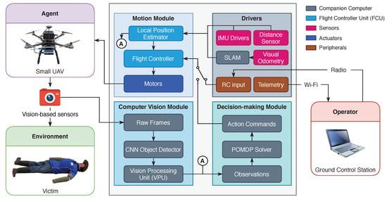
Figure 1.
Proposed modular system architecture for an autonomous onboard navigation in Global Navigation Satellite System (GNSS)-denied environments in small Unmanned Aerial Vehicles (UAVs). It is composed of a computer vision module, which processes raw data from vision-based sensors, a decision-making module which sends low-level action commands to the flight controller, and a motion module that controls the dynamics of the UAV via a set of drivers mounted in the UAV frame.
The UAV contains a set of modules to distribute operations such as collecting and processing data from the environment (computer vision), evaluating the optimal sequence of actions to accomplish the flight mission (decision-making) and managing the speed of the actuators to control the dynamics (or motion) of the UAV. The computer vision and decision-making modules are run on a companion computer attached to the UAV frame, whereas the motion module is managed by the onboard FCU. The UAV also includes a set of drivers to assist the local position estimation in GNSS-denied environments and peripherals to establish communication to the operator. The operator receives real-time telemetry and decides whether to let the UAV interact with the environment or regain manual control using the remote control.
For every interaction cycle while operating the UAV in autonomous mode, the UAV starts capturing data from vision-based sensors in the form of image frames. Those frames are read by the computer vision module which processes these observations into percepts for the decision-making module. The current implementation of this module uses a Deep Convolutional Neural Network (D-CNN) to detect victims. A D-CNN is an artificial neural network designed for processing structured data arrays such as images [44]. The module contains dedicated hardware to meet the computational demand of running D-CNNs on resource-constrained hardware via Vision Processing Units (VPUs). Information produced by the computer vision module details whether a victim is detected in the frame, and if detected, the estimated location of the victim and a summary statistic about the confidence of the detection. The decision-making module reads this data as well as the estimated local position of the UAV (from the motion module) as observations. Then, the POMDP solver determines the corresponding motion command for the next iteration. Finally, these actions are passed to the flight controller which ultimately sends appropriate control signals to the actuators and manoeuvre the aircraft to the desired position.
The UAV requires a set of external sensors from the FCU to successfully operate in GNSS-denied environments. In this implementation, estimations of local UAV positioning are achieved using Light Detection and Ranging (LiDAR)-based distance and visual odometry sensors. It is common when working with visual odometry sensors to externally run (using a companion computer, fox example) visual Simultaneous Localisation and Mapping (SLAM)-based algorithms to provide the FCU with relevant pose and twist data. Modern FCUs contain dedicated algorithms to read localisation data from multiple sensory systems (i.e., IMU, distance sensor and SLAM output) and estimate the local UAV position in real time.
4. Framework Implementation
The implemented hardware and software (i.e., framework) is designed to be as modular as possible based on the system architecture presented in Section 3. First, the paper presents UAV frame, drivers and payload, followed the software communication interface of the system, and software solutions to implement the computer vision and decision-making modules onboard the UAV companion computer.
4.1. UAV Frame and Drivers
The current implementation consists of but it is not restricted to the UAVs and sensors mentioned below. The UAV frame used is a Holybro S500 multi-rotor kit (Holybro, China), which offers a right balance between payload adaptability and size to navigate in cluttered indoor environments. The aircraft features a Pixhawk 4® autopilot (i.e., onboard FCU), 22.86 cm plastic propellers, 2212 KV920 brushless motors, and 433 MHz Telemetry Radio. The aircraft length × width × height dimensions are of 38.3 cm × 38.5 cm × 24.0 cm, with a total load payload capacity of 0.4 kg. The UAV uses a four (4) cell 5000 mAh LiPo battery which provides an approximate flight autonomy of 10 min payload-free and eight minutes with the sensor payload and companion computer mounted in the frame. An illustration of the UAV frame with its payload, companion computer and drivers is shown in Figure 2.
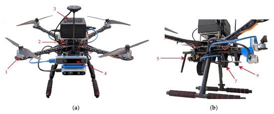
Figure 2.
Proposed UAV frame with mounted drivers, companion computer and payload. (a) Front view of the UAV displaying: (1) Holybro S500 frame; (2) Pixhawk 4® flight controller; (3) UP2 companion computer; and (4) Intel® Realsense™ T265 tracking camera. (b) Lateral view of the UAV displaying: (5) 433 MHz telemetry radio; (6) HBV-1615 RGB camera; and (7) TFMini Plus range sensor.
The companion computer which runs the computer vision and decision-making modules is an UP2 (AAEON Technology Inc., New Taipei City, Taiwan). The computer features a 64-bit quad-core Intel® Pentium® N4200 processor at 1.1 GHz, 8 GB DDR3 RAM, 64 GB eMMC SSD, four FL110 USB 3.0 connectors, two Ethernet controllers, two High-Speed UART controllers, an Intel® Dual Band Wireless-AC 3165 and one mPCIe connector. The UP2 is selected here against similar computer boards owing to its competitive price tag for its provided features, peripherals and the familiar 64-bit CPU architecture.
The UAV requires several sensor drivers to estimate its local position in the absence of GNSS. For these experiments, the list of sensors is composed by the embedded Pixhawk 4® IMU, a TFMini Plus range sensor (Benewake, Beijing, China) pointing downwards which provides the UAV altitude, and an Intel® Realsense™ T265 tracking camera (Intel Corp., CA, US) pointing to the front from the UAV frame. The T265 sensor uses a closed source SLAM software implementation for local position and motion estimation. Configuring the camera to the front improves the reliability of the sensor readings by capturing and detecting more objects (e.g., obstacles, walls, floor and victims) than by pointing the camera to the ground. Collected observations from the environment are performed with a HBV-1615 Red Green Blue (RGB) camera, mounted in a downward-looking configuration from the UAV frame (Figure 2b). The camera features a resolution of 640 × 480 pixels, focal length of 2.484 mm, sensor width of 1.968 mm and sensor height of 1.488 mm. It is worth mentioning that other multi-rotor UAVs, companion computers and drivers with similar characteristics can also be utilised for the proposed system architecture depicted in Figure 1.
4.2. Operating Systems and Middleware
The system modules implemented in the companion computer are developed for 64-bit Linux Operating Systems (OS) and run in Ubuntu Server 18.04. Communication between the vision-based sensors, and computer vision and decision-making modules is achieved using the Robot Operating System (ROS) Melodic [45] middleware. The flight controller runs under NuttX (a real-time OS) and the PX4 flight control software [46]. The PX4 architecture consists of: (1) a flight stack layer, which details a pipeline if flight controllers for multi-rotors, fixed-wing and vertical take-off and landing (VTOL) UAVs, altitude and position estimators, and; (2) A middleware layer, which contains the device drivers for multiple UAV sensors, communication interfaces, and a simulation layer to enable Hardware in the Loop (HIL) capabilities of the FCU.
Communication between the decision-making module (from the companion computer) and the motion module (from the FCU) is done using MAVROS via a High-Speed UART interface. MAVROS is a ROS wrapper of the Micro Air Vehicle Link (MAVLink) protocol, an industry standard for UAV communication [47]. Telemetry to the ground control station was performed using QGroundControl via Wi-Fi and the Holybro 433 MHz Telemetry Radio (Holybro, China).
4.3. Computer Vision Module
This module consists of a deep learning object detector processing raw frames from the HVB-1615 RGB camera. Taking into account the performance limitations of running deep learning models in resource-constrained hardware, a Vision Processing Unit (VPU) is installed to the companion computer. The use of a VPU boosts the computations that allow inference in deep learning models by optimising convolutional operations in its microprocessor. In this implementation, the selected VPU is an Intel® Movidius™ Myriad™ X, which is connected to the companion computer via the mPCIe slot. The detection module is programmed in Python and uses the OpenVINO library that allows a direct interface between various deep learning frameworks and the VPU. OpenVINO supports TensorFlow, Caffee, PyTorch, among other deep learning frameworks. Standard image processing methods are also covered by OpenVINO through optimised versions of the OpenCV and OpenVX libraries.
The used deep learning model architecture to detect persons is an off-the-shelf Google MobileNet Single-Shot Detector (SSD) [48]. This model is deployed in Caffe [49] and tuned with pre-trained weights from the PASCAL VOC2012 dataset [50], scoring a mean average precision of 72.7%. The dataset covers up to 21 class objects (including persons). However, only positive detections for the class person are evaluated. Acquired camera frames are fitted into the input layer of the neural network (i.e., MobileNet SSD model) by shirking the frames into dimensions of 300 × 300 pixels. Once inference is performed onto the fit model, positive detections of persons with a score confidence (from the output layer of the neural network) greater than 60% are depicted in the processed frame and shown to the human operator for telemetry purposes, as displayed in Figure 3.
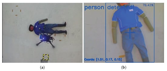
Figure 3.
Victim detection trial using the proposed Google MobileNet Single-Shot Detector (SSD) architecture from Chuanqi [48]. Detections with an output score confidence greater than 60% are displayed in the processed frame. (a) Top view of the UAV flying above an adult mannequin. (b) Victim detected with a confidence score of 78.42% after processing raw frames from the HBV-1615 RGB camera.
Taking into account the nature of PASCAL VOC dataset the object detector was trained for the class person, the frequency and detection scores are significantly higher when the UAV is aligned with the mannequin (as shown in Figure 3b) than with other visual representations. Consequently, the object detector is unable to detect the mannequin if spatial transformations in the x or y axes are applied. Similarly, there are slight chances to detect the mannequin if its lower body is occluded by other objects. The optimal distance between the UAV and the mannequin to maximise the detection scores ranges between 1 m and 10 m. In order to address these limitations on the detections, image rotation transformations are applied on software for each input frame. A total of six transformations (i.e., image rotations every 60) are processed for every read camera frame, achieving, thus, an approximate processing speed of 2.9 Frames per Second (FPS).
4.4. Decision-Making Module
The decision-making module contains algorithms that translate information from the environment (i.e., observations) into action commands. In this implementation, the decision-making module contains the POMDP, in which the navigation problem is required to be formulated. The decision-making module uses ABT—an online POMDP solver [26]—implemented on software using TAPIR [39]. TAPIR is developed in C++ and requires the tuning of several hyper-parameters to obtain the best possible approximation of the POMDP solution (i.e., optimal motion policy). Details on assigned hyper-parameter values for TAPIR can be found in Section 5.2.3.
This paper proposes an approach for a UAV to find a victim in cluttered indoor environments. An example scenario, which is depicted in Figure 4, consists of a limited flying area, several obstacles randomly placed, with weak or absent GNSS signal, and a static victim located inside the area to be surveyed.
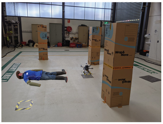
Figure 4.
Example of a cluttered indoor environment for UAV Search and Rescue mission. The extent of the free volumetric space area is restricted by randomly placed obstacles. The victim is always lying on the ground and its location is static.
The estimation of the optimal motion policy allows the UAV to perform efficient obstacle avoidance, victim detection and path planning for various uncertainty levels in the location of the victim. The problem formulation is partially defined based on the following assumptions:
- The UAV pose and motion are estimated by a SLAM-based sensor (i.e., visual odometry) embedded on the UAV frame.
- Observations come from real-time streaming of processed camera frames and the estimated local UAV position from the FCU.
- Flying modes such as take-off and landing are also delegated to the FCU and automatically triggered by the UAV, or the operator if they want to regain control on the UAV motion.
- The task starts after the UAV gets close enough to a chosen starting point.
- The task finishes once the victim is detected with high detection frequency (e.g., exceeding a minimum threshold detection value), or if the UAV runs out of power resources (or timeout) to keep flying before a detection is made.
The text below describes the problem formulation for the elements of the POMDP tuple, which consists of the set of possible taken actions A by the UAV; the system states S; the motion model of the system after an action is executed by the UAV; the system rewards and cost function R; the collected observations O from the environment; the observation model; and the initial belief . The problem formulation is presented as generic as possible in this section. Technical details on the assigned values in the experiments are described in Section 5.
4.4.1. Actions (A)
In the current implementation, the UAV interacts with the environment by applying an action . As shown in Table 1, seven actions have been selected in this paper. However, more actions can be added as per problem requirements such as setting UAV yaw orientation and camera gimbal angle commands.

Table 1.
Set of chosen actions for the problem formulation. Each action is a position command where is the magnitude of change of position coordinates , and from time step k to time step . Position values are referenced to the world coordinate frame.
The above-mentioned actions are position commands defined in the world coordinate frame, where is the magnitude of change of position coordinates , and from time step k to time step . Assigning various values for allows flexibility in the speed of the UAV for big and small flying areas. Other standard UAV actions such as take-off and landing are off-the-shelf commands managed by the onboard FCU and triggered by the system before and after executing the POMDP solver, respectively. A description of the initial conditions of the UAV is covered in detail in Section 5.
4.4.2. States (S)
For this implementation the system states consist of the UAV and victim states. The state of the UAV is defined by the position of the UAV in the world coordinate frame; the UAV instantaneous velocity ; the flag that defines whether the UAV has collided with an obstacle; and the flag which specifies whether the UAV is navigating out of the limits of the region to be surveyed. The victim state is defined by the position of the victim in the world coordinate frame; the flag that determines whether a victim has been detected by the UAV; and the flag that confirms the detection state of the victim, which is defined as:
where is the victim’s detection confidence between time steps. An expanded explanation of and its usage is covered in Section 4.4.5. In the current formulation, , and are considered terminal states (or stopping conditions). Other states such as states for a second or more victims can also be added to the framework.
4.4.3. Motion Model
The motion model for a multi-rotor UAV is defined as:
which can be expanded as:
where is the UAV’s position at time step k; is a simplified multi-rotor rotation matrix after assuming changes in the Euler angle values , and [51]; is the change in the UAV’s position from time step k to time step ; and represents pose estimation errors in the Euler yaw angle of the UAV. This variable is modelled as a normal distribution with a mean of and standard deviation of . An approximation of the dynamic model of the UAV through changes in position () was conducted empirically using the UAV frame and a system identification process. An expanded description for calculation of can be found in Section 5.
4.4.4. Rewards and Cost Function (R)
The cost function R is defined as follows:
where is the negative reward (or penalty) per action taken to encourage the UAV to find the victim in the less number of possible action sequences; is the cost if the UAV crashes itself with an obstacle; is the cost if the UAV flies beyond the survey area limits; is the reward if a victim is detected (regardless of the confidence level), defined as follows:
where is the constant reward value assigned to ; is the Manhattan distance between the UAV and victim; is the reward if the victim is detected with a high confidence level, defined by the threshold (as mentioned above in Equation (4)); and represents the longest length of the search area. Manhattan distance was chosen over Euclidean distance for based on better UAV traversed paths using the former in preliminary simulations. Adding to the cost function aims to get the UAV closer to the believed location of the victim and acquire camera frames with clearer visual representations of them. Nevertheless, might generate ambiguity and sub-optimal behaviour in the UAV if it is surrounded by equidistant victim belief particles. In order to add memory about a path previously traversed by the UAV, R includes , which is the cost for any taken action that places the UAV in a region that was previously explored. An illustration of the concept is shown in Figure 5.
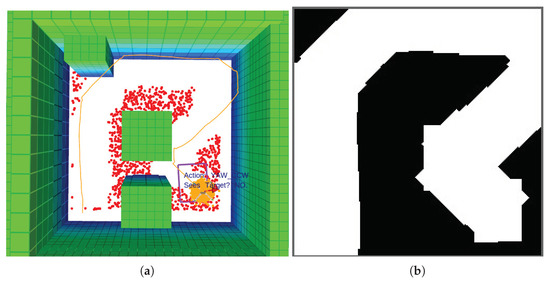
Figure 5.
Example of a recorded trajectory. (a) Traversed path by the UAV. The figure is composed by: The path of the UAV (orange splines); the environment obstacles (green blocks); the UAV position belief (orange point-cloud); the possible victim location coordinates (red point-cloud); and the camera’s Field of View (FOV) (purple rectangle). (b) Traced footprint using the camera’s Field of View (FOV). Future actions that place the UAV inside the white areas trigger .
4.4.5. Observations (O)
The system observations consist of the available information about the state of the environment and the UAV from its sensors. As previously illustrated in Figure 1, certain observations require a pre-processing stage such as the detection and localisation of the victim from vision-based camera frames. The current observations O are defined as:
where is the position of the UAV in the world coordinate frame, which is obtained from the local position estimator of the motion module; is the flag that defines whether there is an obstacle in front of the UAV, which is obtained by reading the location of the UAV inside an occupancy map object (described in Section 4.4.8); is the flag that determines whether a victim has been detected by the computer vision module; and provides the location estimation of the victim, defined as:
observation is a summary statistic that measures the frequency of victim detections between the last and current observation calls (and referred as the detection confidence), defined as:
Other observations such as the orientation of the victim or similar object detection outputs from two or more cameras are not implemented but can also be considered in the formulation.
4.4.6. Observation Model
Considering that ABT uses a generative model that outputs an observation , a reward R and a next state based on a taken action from a current state , probabilistic transition functions T and are not required to be explicitly declared. Therefore, the generative model requires modelling a potential observation o given and a. The observation model is composed by the local position estimation of the UAV in the world coordinate frame, the local position of the victim if it is detected by the vision-based sensors and the detection confidence . Victim detection depends on the footprint extent of the camera’s Field of View (FOV), which is defined by the sensor properties of the camera and . The vertical and horizontal FOV angles are defined as follows:
where w is the sensor width; h is the sensor height; and f is the focal length of the camera. The extent of the observed FOV area (or footprint) is calculated as:
where l is the footprint extent of the camera frame at its top, right, bottom and left limits, and is the pointing angle by the camera gimbal from the vertical z axis, as shown in Figure 6.
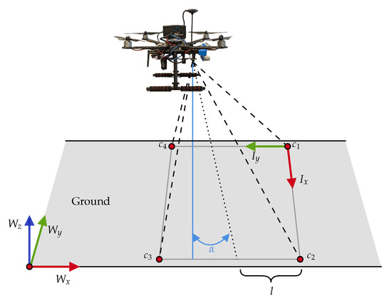
Figure 6.
Two-dimensional (2D) projection of vision-based sensors pointing to the ground, where W is the world coordinate frame, I is the image coordinate frame, is the camera’s gimbal angle from the vertical, are the rectangular corners from the camera’s Field of View (FOV), and l is the footprint extent of the FOV.
The two-dimensional (2D) projection corner coordinates of the camera’s FOV are defined as:
Following Equation (5), a transformation matrix is also applied to link the FOV corners to the UAV reference frame:
where is the pose estimation error in the Euler yaw angle of the UAV (mentioned in Equation (5). If the projected 2D point coordinate of the victim is located within the corner c points from the formed rectangular footprint, the victim is assumed to be visualised in the camera’s FOV. As defined in Equation (21), an angle is calculated as the sum of angles between the victim’s position and each pair of points that comprise the FOV corners [52],
If , the coordinate point of the victim is inside the camera’s FOV. Nevertheless, this calculation assumes perfect detection outputs from any vision-based model implemented in the computer vision module. Uncertainty from computer vision models (including deep learning detectors) come from factors such as noise from the camera frames, poor illumination conditions, low image resolution, occlusion from obstacles and sub-optimal camera settings. Even though it is possible to allocate extra resources to improve the performance of these object detection models, this paper presents an approach that covers detection uncertainty. Some factors that cause uncertainty such as the display of false positives are simulated here by incorporating the object detection confidence and evaluating such confidence with thresholds in the problem formulation. In this implementation is modelled using a linear regressor, defined in Equation (22):
where is the minimum detection confidence threshold; and are the minimum and maximum allowed flying altitudes respectively; g is the distance gap applied to ; and is the Manhattan distance between the UAV and the victim.
4.4.7. Initial Belief ()
Formulating the problem as a POMDP allows modelling uncertainty and partial observability with probabilistic data distributions. The proposed system contains two sets of belief states: The position of the UAV, and the position of the victim. The position of the UAV is defined as a normal probability distribution with mean and standard deviation . As previously shown in Figure 5a, the position of the victim can be defined as a uniform probability distribution or as a set of one or more normal distributions placed across the flying area. This capability allows the rescue personnel and UAV operator to freely define possible areas where a victim could be located, following the concept of situational awareness in SAR operations. Details on the specific configurations used in the experiments can be found in Section 5.2.2.
4.4.8. Obstacle Avoidance
The decision-making module relies on the concept of occupancy maps for obstacle avoidance. Occupancy maps are represented in three-dimensional (3D) occupancy grids whose cells contain binary values for the specific volumetric representation of space such as free, occupied or unknown. The occupancy map for this task was generated using the Octomap library [53], which allow the creation of occupancy maps using 3D point clouds, data that is commonly acquired from depth cameras and LiDAR sensors. In this work, the octomap of the environment was generated manually and read by the decision-making module prior to any flight campaigns (in simulation and hardware).
5. Experiments
The presented system is tested for a victim finding mission in a cluttered indoor environment using HIL simulations and real flight tests. The text below describes the environment setup and assigned values to the formulated POMDP problem presented in Section 4.4.
5.1. Environment Setup
The search area has length × width × height dimensions of 6 m × 6 m × 3 m. As shown in Figure 7, the surveyed area contains several obstacles in the shape of columns, the victim is lying on the ground and located at the opposite end from the take-off position of the UAV. The victim and column obstacles are static and no disturbances such as wind or variable light conditions are applied to the setup. Due to the limited flying space available in the testing facility for hardware tests, it was not possible to evaluate the system in an environment with bigger dimensions that suit more realistic SAR operations. However, the focus and contribution of this paper relies on: introducing a framework for autonomous UAV operations in GNSS-denied environments under partial observability; illustrating a system architecture that incorporates and executes computer intensive deep learning models (for realistic object detection) and online POMDP solvers onboard resource-constrained hardware; and presenting a proof of concept of the system robustness in SAR scenarios, with the potential of operating the system in more challenging conditions.
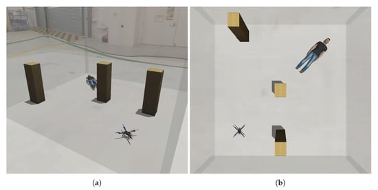
Figure 7.
Environment setup for autonomous UAV victim finding in HIL simulations and real-flight tests. The victim is static and is always located at the opposite end from the take-off position of the UAV. (a) Isometric view of the environment simulated in Gazebo. (b) Top view of the environment simulated in Gazebo.
The example environment is validated with HIL simulations and hardware experiments. Simulation experiments are executed using a desktop workstation, replicating the environment setup using the Gazebo ROS Simulator. The desktop workstation features a 64-bit 12-core Intel® Core® i7-8700 CPU at 3.2 GHz, a 32 GB DDR4 RAM, a 512 GB eMMC Solid State Drive, a 6 GB NVIDIA GeForce GTX 1060, six (6) USB 3.0 ports and an Ethernet controller.
Hardware experiments are conducted at the Queensland University of Technology (QUT) Da Vinci Precinct (DVP) hangar area, 24/22 Boronia Rd, Brisbane Airport, QLD 4008, Australia. Data collection campaign occurs in four (4) opportunities from the 25 June 2020 to the 2 July 2020 between 11:00 a.m. and 3:00 p.m. For safety reasons, an adult mannequin is used as the victim to be detected, as shown in Figure 8. Illumination conditions are controlled by exposing the setup with a constant light intensity from fluorescent light bulbs. No external wind disturbances are applied during the data collection process.
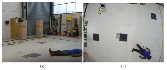
Figure 8.
Environment setup for hardware experiments. For safety reasons, an adult mannequin is used as the victim to be detected and column obstacles are replaced with carpet tiles. (a) UAV navigating inside a netted area at the Queensland University of Technology (QUT) Da Vinci Precinct (DVP) hangar. (b) Top view of the setup with the mannequin displayed at the bottom.
In the setup neither a depth camera nor LiDAR sensor is included in this framework implementation. The system is therefore limited to operate using a fixed occupancy map of the environment. Despite this limitation, the proposed framework allows extending the system capabilities by incorporating any of the above-mentioned sensors to the UAV frame and updating the map mid-flight using the Octomap library flawlessly. Taking into account that local UAV position estimations from the visual odometry sensor (i.e., T265 tracking camera) are not corrected from any ground truth data source, the environment column-shaped obstacles (Figure 7 and Figure 8a) are replaced by carpet tiles to ensure the integrity of the aircraft in real flight tests (Figure 8b).
5.2. POMDP Problem Formulation
The text below describes the assigned values for variables presented in the POMDP formulation (Section 4.4). They consist of the approximated response of the controlled UAV dynamic system, the case studies of situational awareness (or initial belief) on the victim’s position, and TAPIR hyper-parameter values.
5.2.1. Controlled UAV System Response
In this research, the position changes of the UAV () are modelled by identifying the transfer function of the entire controlled UAV system, composed by the controller, the UAV motors, sensors and feedback loop. Consider y as the independent position response of the UAV for the x, y and z Cartesian frame. A step response of the aircraft is measured after triggering a constant position setpoint m. For each coordinate axis, incremental and decremental step responses are recorded for five seconds between each change using a VICON motion capture system (Vicon, Oxford, UK) as ground truth. The recorded data is processed using the MATLAB® System Identification Toolbox™, which estimates the transfer function of the UAV in the frequency domain (s). The transfer functions of the UAV for x, y and z in the frequency domain are defined as follows:
Afterwards, the transfer functions were discretized using the Tustin approximation method, defined in Equation (26):
where (i.e., s) is the sampling period. The UAV motion is calculated by obtaining the difference equation of the discretized system after applying the inverse Z-transform, as defined from Equation (27) to Equation (30):
where N is the order of the transfer function ; and represent previous setpoint and response values respectively; and and are the numerical constants for each and function variables.
5.2.2. Uncertainty and Initial Belief ()
As shown in Figure 9, the possible location of the victim was evaluated following three case studies, which are inspired on available information (situational awareness) from a SAR perspective: (1) single cluster of position points following a normal probability distribution with mean and standard deviation (Figure 9a); (2) two position clusters defined as normal probability distributions with the second cluster declared with mean and standard deviation (Figure 9b); (3) a uniform probability distribution assuming that there is no knowledge of where the victim might be located in the surveyed area (Figure 9c). It is worth mentioning that the physical mannequin was always located at position coordinates and orientation from the world coordinate frame.
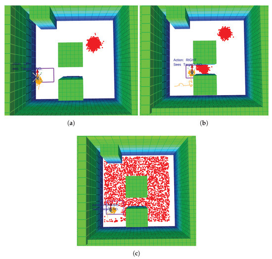
Figure 9.
Tested case studies of search and rescue situational awareness regarding the victim location. Orange splines represent the path of the UAV; green blocks are the environment obstacles; the orange point-cloud is the UAV position belief; the red point-cloud is the victim position belief; and the purple rectangle the camera’s Field of View (FOV). (a) Victim position points distributed in a single cluster. (b) Victim position points distributed in two clusters. (c) Cluster of victim position points uniformly distributed along the flying area.
5.2.3. TAPIR Hyper-Parameters
TAPIR requires tuning several hyper-parameters to obtain the best possible approximation of the POMDP solution (i.e., optimal motion policy). For these experiments, the offline policy timeout is set to five (5) seconds, the maximum belief tree depth is of 100 nodes, time steps are of one (1) second, and the discount factor . The UAV is conditioned to find the victim for a maximum of 480 iterations (equivalent to approx. eight minutes of flight time). The minimum and maximum flying altitudes of the UAV are of 1.0 m and 1.8 m respectively. Specific values for the POMDP variables defined in Section 2.1 are shown in Table 2.

Table 2.
Hyperparameter values for the Partially Observable Markov Decision Process (POMDP) formulated problem. The initial belief position and orientation values were defined in reference to the world coordinate frame.
Where is the magnitude of change of UAV position coordinates between time steps (i.e., s, m/s) for the x, y and z Cartesian axes; the set of variables constitute the system rewards defined in Section 4.4.4; is the minimum victim detection confidence that should be achieved by the UAV; the set of variables defined in the initial belief defined in Section 5.2.2; and g is the distance gap applied to the minimum UAV altitude defined in Section 4.4.5; The assigned values for the system rewards are found after performing grid-search into the ABT solver.
6. Results
A set of success metrics were evaluated for each one of the three situational awareness case studies regarding the covered area(s) where the victim was believed to be located: victim position points distributed in single, dual and uniform clusters (as discussed in Section 5.2.2). The metrics consisted on the victim confirmation rate (i.e., ), the victim miss rate (i.e., ), the UAV collision rate (i.e., ), the UAV navigation rate flying beyond the area limits (i.e., ), the occurrences where the aircraft followed a sub-optimal path, and the timeout rate (i.e., steps, or s). A summary of the collected metrics is shown in Table 3:

Table 3.
Performance metrics for Hardware in the Loop (HIL) simulations (S) and real flight tests (FT), where is the weighted average of the measured variables.
Where “Detections” measures the instances where the victim was detected with . Otherwise, failed instances were either classified as “Misses” if , “Sub-optimal Path” if the UAV got stuck in a patch that does not cover the victim’s location, or “Timeout” if the UAV consumed all the flying time () without detecting the victim.
Overall, the presented system achieved a victim confirmation rate for all the cluster belief configurations of in simulation and in flight tests. For experiments with single clusters, a slight difference in the detection confidence was found between simulation and flight tests. An increase on the setup complexity by the victim silhouette, scene and camera conditions was attributed to lower victim detection confidence values during real flight tests. Namely, the imperfect anthropomorphic properties of the mannequin compared to its simulation counterpart and lower image quality from the RGB camera, represented a cost in the performance of the computer vision module to detect a person. A similar finding was discovered in tests with dual but not with uniform declared clusters. This behaviour could be attributed to the bigger search space required to find the victim using uniform clusters than with the former. In addition, the UAV was unable to detect a victim in of the flight tests with dual cluster declarations because of a sub-optimal UAV trajectory. This behaviour was also present but less frequent in of HIL simulation experiments under uniform cluster declaration. A few timeout stopping conditions were also triggered in missions with uniform clusters because the UAV kept navigating in unexplored areas after flying above and not detecting the mannequin. Lastly, none of the experiments triggered terminal states caused by collisions or UAV trajectories violating the flying area limits.
The most frequent trajectories generated by the UAV in experiments with single clusters are displayed in Figure 10. A set of arrows drawn on top of the UAV path represent the actions taken at every time step to clarify the influence of the decision-making module over the behaviour and stability of the aircraft during the missions.
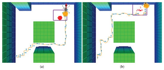
Figure 10.
Flight mission examples of most frequent types of UAV trajectories under a single belief cluster. Orange splines represent the path of the UAV; the blue arrows are action commands per time step; green blocks are the environment obstacles; the orange point-cloud is the UAV position belief; the red point-cloud is the victim position belief; and the purple rectangle the camera’s Field of View (FOV). (a) UAV motion policy which crosses two of the column-shaped obstacles. (b) UAV motion policy which avoids crossing two of the column-shaped obstacles.
Simulation and flight tests with dual clusters evidenced just one type of generated trajectory as opposed to the first case study, as shown in Figure 11. Positioning one of the clusters between two of the environment obstacles caused the UAV to explore such area patch first (owing to be at a closer distance than the cluster at the top). As expected, the UAV followed the same navigation route once it cleared the first cluster as this strategy requires less time steps than alternative routes.
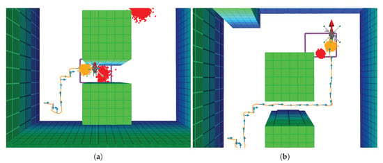
Figure 11.
Flight mission example trajectory under two defined belief clusters. (a) UAV motion policy status when it reached the first cluster. (b) UAV motion policy after clearing the first cluster and reaching the second cluster.
The behaviour of the UAV with uniform clusters slightly differed compared to other case studies. Even though the UAV executed motion policies following similar global trajectories as with the first discussed case study (crossing and avoiding obstacles), a zigzag pattern was visualised as illustrated in Figure 12.
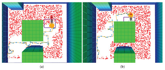
Figure 12.
Example global trajectories followed by the UAV under a uniform belief cluster in flight tests. (a) Motion policy that encourages the UAV to cross over the column obstacles. (b) Motion policy that encourages the UAV that avoids crossing over the column obstacles.
For real flight tests where the victim was not detected, the traversed path by the UAV followed a pattern to cover remaining unexplored areas until it reached its maximum endurance, as shown in Figure 13.
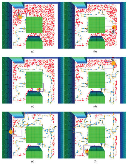
Figure 13.
Example traversed path in a real flight test if a victim is undetected under a uniform belief cluster. (a) Traversed path at time step ; (b) ; (c) ; (d) ; (e) ; (f) .
During the data collection process through real flight tests, the UAV experienced small stability problems in some runs, as seen in Figure 14. The issues altered the smoothness of the UAV trajectory but did not cause any consequence for the mission goal of finding the victim.
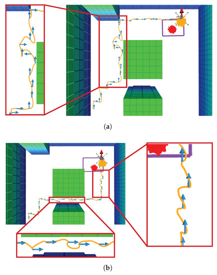
Figure 14.
Stability anomalies on the traced UAV trajectory during real flight tests. (a) Noisy UAV trajectory in a mission with single belief cluster. (b) Noisy UAV trajectory in a mission with dual belief cluster.
Each one of the displayed arrows illustrate the action commands from the decision-making module at every time step. The arrows indicate how the UAV was still capable of following a consistent motion policy despite the added uncertainty by the aggressive motion response of the UAV. An analysis of recorded flight logs suggests that these perturbations in the UAV motion were caused by a sub-optimal performance of the FCU position controller. Specifically, the constant mounting and dismounting of the UAV LiPo battery during real flight tests provoked unintentional balancing issues, which may have altered the transition function of the UAV from which the flight controller was tuned by default. A graphical comparison of the UAV position response between two sets of flights is shown in Figure A1 and Figure A2. The results suggest, however, that the system is robust enough to account for uncertainties caused by position estimation errors from the UAV motion module and still accomplish the flight mission.
An analysis of executed time steps to find the victim with a detection confidence was also conducted to assess the performance of the system by analysing repeatability in the measurements and gaps between HIL simulations and real flight tests. Box plots summarising the nature of collected data are shown in Figure 15.
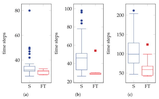
Figure 15.
Data distribution of executed time steps by the POMDP solver until the victim was detected with a confidence and position coordinate . HIL simulations (S) are indicated in blue and real flight tests (FT) in red. (a) Results under a single victim belief cluster. (b) Results under two victim belief clusters. (c) Results under a uniform belief cluster.
Experiments defined with a single belief cluster (Figure 15a) presented a median of 32 and 31 time steps in simulation and flight tests respectively. Tests with dual (Figure 15b) and uniform belief clusters (Figure 15c) reported a higher variance with median values of 46.5 and 29 time steps, and 99.5 and 59.5 time steps respectively. The variance in the length of the whiskers between simulation and flight tests in all the case studies was caused by the equations that define the UAV motion in Gazebo. Those functions approximate by default the motion response of a generic multi-rotor UAV rather than the Holybro S500 frame utilised for this research.
Bigger top whiskers and several outliers were also present in the distribution of collected data. These abnormal time step values and data asymmetry occurred as part of the proposed problem formulation, where victim belief particles are repopulated in the flying area only if the UAV finishes exploring the area of interest and is unable to find any victims. As a result, the UAV was prompted to further explore again and iterate around the cluster area. Additional time steps were also registered in situations where the UAV was able to detect a victim but with a confidence rate below the defined threshold value. In these situations, the UAV was encouraged to take additional actions in order to increase the confidence rate and confirm a detection. Some examples of recorded simulation test outliers are shown in Figure 16.
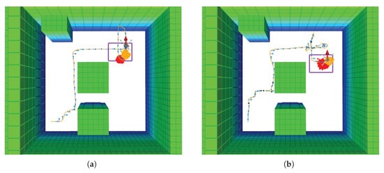
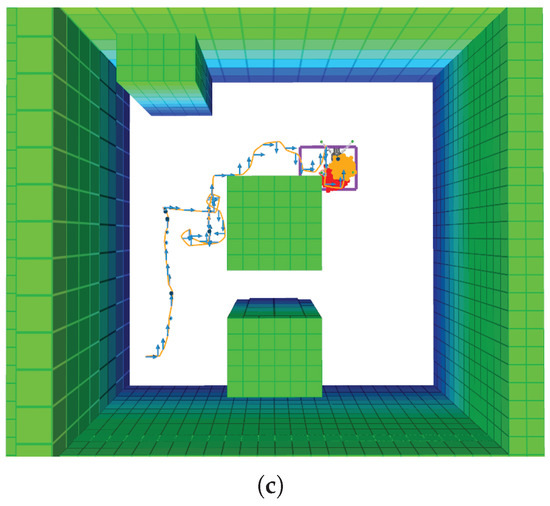
Figure 16.
Anomalies on the amount of executed time steps in simulation. (a) Example trajectory with repopulated single cluster. (b) Example trajectory for an initially defined dual cluster, repopulated after low detection confidence values. (c) Example abnormal trajectory under a uniform cluster.
7. Discussion
The proposed system architecture represents a competitive approach in the domain of onboard UAV decision-making under environment uncertainty and partial observability in GNSS-denied environments. This research extends the contributions of Vanegas and Gonzalez [24] by running the computer vision and decision-making modules onboard the UAV companion computer instead of using an external workstation and having a strong dependency from communication modules to transfer and process the data. Furthermore, the complexity for the target detection task was increased by detecting an adult mannequin instead of predefined augmented vision markers. Similarly, results obtained by Sandino et al. [40] are further enhanced by: (1) offering a more robust simulation environment (PX4 flight controller and onboard computer in HIL) and a more comprehensive system evaluation illustrating results in both simulation and hardware and; (2) extending the problem formulation by incorporating detection errors from the computer vision module (through the modelling of the detection confidence in the problem formulation, covered in Section 4.4.5), rather than assuming detections with null instances of false positives. Obtained results also suggest that the traced trajectories by the UAV became smoother after including a concept of memory by recording previously explored areas from the flying area and adding the reward (defined in Section 4.4.4) in the reward function.
Overall, this study presents a flexible framework that provides scalability through portability depending on the flight mission goals, provided sensors and run algorithms for vision and decision-making. The mathematical formulation of the problem as a model-based POMDP brings enough flexibility to expand the functionality of the system with other multi-rotor UAVs of variable size as long as the dynamic model of the aerial platform and the environment are available to the researchers. The problem formulation covered in Section 4.4 is not specific to the scope of the experimental design of this paper and can be expanded to bigger surveying areas with more complex occupancy map representations. In fact, the UAV motion and flying boundaries of the UAV and victim can be increased without impacting the performance of the ABT solver, Octomap and TAPIR toolkits.
Despite the progress discussed in this paper, there are still several challenges which need to be addressed in the future. First, the occupancy map was provided before flying the aircraft and it was not updated mid-flight. Even though it is possible to reconstruct occupancy maps by using, for example, existing building floor plans of the surveyed area, it might not be suitable to fly in more complex environments with dynamic obstacles. Additionally, not updating the occupancy map online constitutes a strong dependency on the local position estimation system (i.e., visual odometry sensor). Indeed, the risk of the UAV colliding with other obstacles increases if position estimation errors are high. Augmenting the proportion of the obstacles was an applied workaround during the data collection process. Under the assumption of operating with preloaded occupancy maps, the system complexity was simplified by not including UAV actions such changes in its heading direction. However, it is possible to either incorporate heading actions in the problem formulation and disregard the backward, left and right action commands, or include additional sensors which can provide enough sensing coverage around the UAV in future experiments. The use of one or many depth cameras or a LiDAR sensor to update the occupancy map mid-flight might diminish the likelihood of collisions, regardless of the error magnitude of the local position estimation algorithm. Second, the off-the-shelf model to detect persons might not produce the expected performance at more complex experiment setups. For instance, detections are likely to be poor when the person is visualised in conditions from which the detector was not trained for such as debris occluding the person and if the person is observed from other camera perspectives as the one shown in Figure 3b.
Previous research also indicates the convenience of using sensors to detect bio-signals from humans, such as microphones for audio signals, thermal cameras, gas sensors and Doppler radars for breathing and heart-beating signals respectively [54,55,56]. Bio-signals have also been proven to be detected through the use of computer vision and RGB cameras as long as UAVs are positioned closed enough to the victims [15]. Even though the employed MobileNet SSD detector is efficient enough to distinguish the presence of persons regardless of their health conditions, the modularity design presented in the system architecture allows adding other vision-based detectors without substantial modifications, so that they could provide further valuable data to the decision-making module (in the form of observations), UAV operators and SAR squads. Additional sensors such as thermal and depth cameras can also be added to the UAV frame without altering the workflow of the system architecture. Moreover, other decision-making algorithms could also be ported to the framework with ease, such as model-free reinforcement learning, Observe–Orient–Decide–Act (OODA) loops, Bayesian networks, etc. Nevertheless, a comparison study between the trade-offs of other decision-making algorithms for UAV navigation under environment uncertainty should be reviewed in future research before adapting them to the framework.
A successful implementation of the proposed system in real disaster events requires the examination of various practical challenges, which include but are not limited to:
- The size of UAV, which may restrict the survey in very confined places and compromise the integrity of the UAV and nearby victims, if any.
- Low lighting conditions, which might decrease the performance of the visual odometry system and people/object detector.
- The UAV endurance, which could constrain SAR operations if the remote assessment of a hazardous structure exceeds 20 min of flying time.
- Collisions, which may occur owing to the absence of propeller protectors or if victims make accidental contact with the UAV.
- Chemical and electrical hazards present in the surveyed area, which may compromise electronic circuits and sensors.
- Mishandling of LiPo batteries, which might provoke fire hazards if not isolated from impacts and ignition sources.
An additional extension to the UAV frame could be the incorporation of a front-view camera, which will aid the assessment and SAR logistics if physical intervention to the surveyed structure is necessary.
8. Conclusions and Future Work
This paper presented a framework for automated UAV motion planning under target location uncertainty in cluttered, GNSS-denied environments. The system architecture details the functionality of system modules for unsupervised decision making onboard resource-constrained hardware platforms such as small UAVs (MTOW ≤ 13.5 kg). The proposed approach is illustrated in the SAR context by locating a victim in a simulated office building. The system is validated using HIL simulations to ensure a high-fidelity setup against real-world conditions; and real flight tests using a multi-rotor UAV frame and vision-based sensors for SLAM and collection of system observations.
The problem is mathematically formulated as a POMDP, whose probabilistic model allows representing uncertainty with probability distributions. This approach allows defining potential locations of the victim with normal and uniform probabilistic distributions (and, thus, model victim location uncertainty). The performance of the UAV was evaluated under three case studies of situational awareness; a single cluster of victim coordinates covering a small patch from the surveyed environment; two clusters of victim coordinates covering two areas of interest; and a cluster of victim coordinates uniformly distributed across the flying area. Incorporating the ABT algorithm as the POMDP solver does not only provide the system with a UAV motion policy in seconds prior to any flight mission, but it also improves previously computed policies mid-flight by modelling potential changes in the environment and levels of uncertainty based on possible future actions in its internal search tree. This feature allows the UAV to optimise its behaviour in various scenarios such as preserving a constant path under unstable UAV motion response or holding its position while more episodes and internal simulations are generated to execute a better policy. Ultimately, the system ensures rapid monitoring and personal safety by letting the UAV to explore the area without UAV operator intervention.
The primary contributions of this paper are:
- A UAV framework for autonomous navigation under target detection uncertainty. The computer vision and decision-making modules run onboard resource-constrained hardware (i.e., a companion computer mounted to the UAV), discarding the dependency of the UAV from third-party systems to perform its motion policy calculations. The framework offers enough flexibility to expand or adapt the functionality of the system by using other vision or light-based sensors, UAV frames and onboard computing hardware.
- An approach to handle target detection uncertainty from false positive detection instances through the concept of detection confidence and the definition of a confirmed detection in the POMDP problem formulation.
- A detailed case study of the implementation of the system modules for a simulated land SAR mission in GNSS-denied environments, which allows integrating the flight controller and companion computer under HIL simulations to bridge the gap between simulations and real flight tests.
A recorded system demonstration can be observed using the following link: https://youtu.be/fEWVd-GC7Fs.
Future avenues for research include evaluation of the performance of the system with an unknown environment map, dynamic obstacles and the robustness of the POMDP solver under environment changes by updating the occupancy map mid-flight. An additional system performance analysis by locating the victim at various locations and finding multiple victims might help to understand the limits of the proposed framework. A study comparing the performance between the ABT solver and other model-based POMDP solvers, and other decision-making algorithms should also be conducted. Evaluating the performance of the UAV using an object detector tuned with a domain-specific dataset (i.e., footage of people in distress and at various occlusion levels) will aid the understanding of the UAV capacity to detect victims under more challenging scenarios. Incorporating widely used sensors for land SAR such as thermal cameras as well as processing camera frames at variable gimbal angle configurations is expected to be conducted in future system implementations.
Author Contributions
Conceptualisation, J.S., F.V., F.M. and F.G.; methodology, J.S., F.V. and F.G.; hardware conceptualisation and integration, F.V.; software, J.S. and F.V.; validation, J.S.; formal analysis, J.S.; investigation, J.S. and F.V.; resources, F.G.; data curation, J.S.; writing–original draft preparation, J.S.; writing–review and editing, F.V., F.M., P.C., C.S. and F.G.; visualisation, J.S.; supervision, F.M., P.C., C.S. and F.G.; project administration, F.G.; funding acquisition, P.C. and F.G. All authors have read and agreed to the published version of the manuscript.
Funding
This research was funded by The Commonwealth Scientific and Industrial Research Organisation (CSIRO) through the CSIRO Data61 PhD and Top Up Scholarships (Agreement 50061686), The Australian Research Council (ARC) through the ARC Discovery Project 2018 “Navigating under the forest canopy and in the urban jungle” (grant number ARC DP180102250) and The Queensland University of Technology (QUT) through the Higher Degree Research (HDR) Tuition Fee Sponsorship. The APC was funded by the QUT Office for Scholarly Communication (OSC).
Acknowledgments
The authors acknowledge continued support from the Queensland University of Technology (QUT) through the Centre for Robotics. The authors would also like to gratefully thank the QUT Research Engineering Facility (REF) team for their technical support that made possible conducting this research work.
Conflicts of Interest
The authors declare no conflict of interest. The funders had no role in the design of the study; in the collection, analyses, or interpretation of data; in the writing of the manuscript, or in the decision to publish the results.
Abbreviations
The following abbreviations are used in this manuscript:
| 2D | Two-dimensional |
| 3D | Three-dimensional |
| ABT | Augmented Belief Trees |
| D-CNN | Deep Convolutional Neural Network |
| FCU | Flight Controller Unit |
| FOV | Field of View |
| FPS | Frames per Second |
| GNSS | Global Navigation Satellite System |
| HIL | Hardware in the Loop |
| LiDAR | Light Detection and Ranging |
| MDP | Markov Decision Process |
| MTOW | Maximum Take-off Weight |
| OS | Operating System |
| POMCP | Partially Observable Monte Carlo Planning |
| POMDP | Partially Observable Markov Decision Process |
| RGB | Red, Green, Blue |
| ROI | Region of Interest |
| ROS | Robot Operating System |
| SAR | Search and Rescue |
| SIL | Software in the Loop |
| SLAM | Simultaneous Localisation and Mapping |
| SSD | Single Shot Detector |
| TAPIR | Toolkit for approximating and Adapting POMDP solutions In Real time |
| UAV | Unmanned Aerial Vehicle |
| VPU | Vision Processing Unit |
Appendix A
Figure A1 and Figure A2 show an example UAV position response comparison between a smooth and a noisy traversed path.
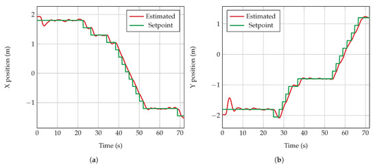
Figure A1.
UAV position response for a smooth traversed path for (a) x and (b) y axes.
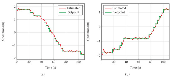
Figure A2.
UAV position response for a noisy traversed path for (a) x and (b) y axes.
References
- Doocy, S.; Daniels, A.; Packer, C.; Dick, A.; Kirsch, T.D. The Human Impact of Earthquakes: A Historical Review of Events 1980–2009 and Systematic Literature Review. PLoS Curr. 2013. [Google Scholar] [CrossRef] [PubMed]
- Shapira, S.; Levi, T.; Bar-Dayan, Y.; Aharonson-Daniel, L. The impact of behavior on the risk of injury and death during an earthquake: A simulation-based study. Nat. Hazards 2018, 91, 1059–1074. [Google Scholar] [CrossRef]
- Cobum, A.; Spence, R.J.S.; Pomonis, A. Factors determining human casualty levels in earthquakes: Mortality prediction in building collapse. In Proceedings of the Earthquake Engineering, Tenth World Conference, Madrid, Spain, 19–24 July 1992; IIT Kanpur: Balkema, Rotterdam, 1992; pp. 5989–5994. [Google Scholar]
- Pajares, G. Overview and Current Status of Remote Sensing Applications Based on Unmanned Aerial Vehicles (UAVs). Photogramm. Eng. Remote Sens. 2015, 81, 281–330. [Google Scholar] [CrossRef]
- Dalamagkidis, K.; Valavanis, K.P.; Piegl, L.A. On Integrating Unmanned Aircraft Systems into the National Airspace System; Springer: Dordrecht, The Netherlands, 2012; pp. 1–305. [Google Scholar] [CrossRef]
- Erdelj, M.; Natalizio, E. UAV-assisted disaster management: Applications and open issues. In Proceedings of the International Conference on Computing, Networking and Communications, Kauai, HI, USA, 15–18 February 2016; pp. 1–5. [Google Scholar] [CrossRef]
- Jiménez López, J.; Mulero-Pázmány, M. Drones for Conservation in Protected Areas: Present and Future. Drones 2019, 3, 10. [Google Scholar] [CrossRef]
- Estrada, M.A.R.; Ndoma, A. The uses of unmanned aerial vehicles –UAV’s- (or drones) in social logistic: Natural disasters response and humanitarian relief aid. Procedia Comput. Sci. 2019, 149, 375–383. [Google Scholar] [CrossRef]
- Karaca, Y.; Cicek, M.; Tatli, O.; Sahin, A.; Pasli, S.; Beser, M.F.; Turedi, S. The potential use of unmanned aircraft systems (drones) in mountain search and rescue operations. Am. J. Emerg. Med. 2018, 36, 583–588. [Google Scholar] [CrossRef]
- Mavroulis, S.; Andreadakis, E.; Spyrou, N.I.; Antoniou, V.; Skourtsos, E.; Papadimitriou, P.; Kasssaras, I.; Kaviris, G.; Tselentis, G.A.; Voulgaris, N.; et al. UAV and GIS based rapid earthquake-induced building damage assessment and methodology for EMS-98 isoseismal map drawing: The June 12, 2017 Mw 6.3 Lesvos (Northeastern Aegean, Greece) earthquake. Int. J. Disaster Risk Reduct. 2019, 37, 101169. [Google Scholar] [CrossRef]
- Zhang, R.; Li, H.; Duan, K.; You, S.; Liu, K.; Wang, F.; Hu, Y. Automatic Detection of Earthquake-Damaged Buildings by Integrating UAV Oblique Photography and Infrared Thermal Imaging. Remote Sens. 2020, 12, 2621. [Google Scholar] [CrossRef]
- Claesson, A.; Svensson, L.; Nordberg, P.; Ringh, M.; Rosenqvist, M.; Djarv, T.; Samuelsson, J.; Hernborg, O.; Dahlbom, P.; Jansson, A.; et al. Drones may be used to save lives in out of hospital cardiac arrest due to drowning. Resuscitation 2017, 114, 152–156. [Google Scholar] [CrossRef]
- Claesson, A.; Bäckman, A.; Ringh, M.; Svensson, L.; Nordberg, P.; Djärv, T.; Hollenberg, J. Time to Delivery of an Automated External Defibrillator Using a Drone for Simulated Out-of-Hospital Cardiac Arrests vs. Emergency Medical Services. JAMA 2017, 317, 2332. [Google Scholar] [CrossRef]
- Ballous, K.A.; Khalifa, A.N.; Abdulwadood, A.A.; Al-Shabi, M.; El Haj Assad, M. Medical kit: Emergency drone. In Unmanned Systems Technology XXII; Shoemaker, C.M., Muench, P.L., Nguyen, H.G., Eds.; SPIE: Bellingham, WA, USA, 2020; Volume 11425, p. 39. [Google Scholar] [CrossRef]
- Al-Naji, A.; Perera, A.G.; Mohammed, S.L.; Chahl, J. Life Signs Detector Using a Drone in Disaster Zones. Remote Sens. 2019, 11, 2441. [Google Scholar] [CrossRef]
- Mishra, B.; Garg, D.; Narang, P.; Mishra, V. Drone-surveillance for search and rescue in natural disaster. Comput. Commun. 2020, 156, 1–10. [Google Scholar] [CrossRef]
- Stark, B.J.; Chen, Y.Q. Remote Sensing Methodology for Unmanned Aerial Systems. In Unmanned Aircraft Systems; Atkins, E.M., Ollero, A., Tsourdos, A., Eds.; Wiley: New York, NY, USA, 2016; Chapter 2; pp. 17–27. [Google Scholar]
- Bähnemann, R.; Pantic, M.; Popović, M.; Schindler, D.; Tranzatto, M.; Kamel, M.; Grimm, M.; Widauer, J.; Siegwart, R.; Nieto, J. The ETH-MAV Team in the MBZ International Robotics Challenge. J. Field Robot. 2019, 36, 78–103. [Google Scholar] [CrossRef]
- Carrio, A.; Sampedro, C.; Rodriguez-Ramos, A.; Campoy, P. A Review of Deep Learning Methods and Applications for Unmanned Aerial Vehicles. J. Sensors 2017, 2017, 1–13. [Google Scholar] [CrossRef]
- Bravo, R.Z.B.; Leiras, A.; Cyrino Oliveira, F.L. The Use of UAVs in Humanitarian Relief: An Application of POMDP-Based Methodology for Finding Victims. Prod. Oper. Manag. 2019, 28, 421–440. [Google Scholar] [CrossRef]
- Kochenderfer, M.J. Decision Making under Uncertainty: Theory and Application; MIT Press: Cambridge, MA, USA, 2015; pp. 1–323. [Google Scholar]
- Hubmann, C.; Schulz, J.; Becker, M.; Althoff, D.; Stiller, C. Automated Driving in Uncertain Environments: Planning With Interaction and Uncertain Maneuver Prediction. IEEE Trans. Intell. Veh. 2018, 3, 5–17. [Google Scholar] [CrossRef]
- Rizk, Y.; Awad, M.; Tunstel, E.W. Decision Making in Multiagent Systems: A Survey. Trans. Cogn. Dev. Syst. 2018, 10, 514–529. [Google Scholar] [CrossRef]
- Vanegas, F.; Gonzalez, F. Enabling UAV Navigation with Sensor and Environmental Uncertainty in Cluttered and GPS-Denied Environments. Sensors 2016, 16, 666. [Google Scholar] [CrossRef]
- Silver, D.; Veness, J. Monte-Carlo Planning in Large POMDPs. In Advances in Neural Information Processing Systems 23; Lafferty, J.D., Williams, C.K.I., Shawe-Taylor, J., Zemel, R.S., Culotta, A., Eds.; Curran Associates, Inc.: Vancouver, BC, Canada, 2010; pp. 2164–2172. [Google Scholar]
- Kurniawati, H.; Yadav, V. An Online POMDP Solver for Uncertainty Planning in Dynamic Environment. In Robotics Research. Springer Tracts in Advanced Robotics; Inaba, M., Corke, P., Eds.; Springer: Cham, Switzerland, 2016; Volume 114, pp. 611–629. [Google Scholar] [CrossRef]
- Garrido-Jurado, S.; Muñoz-Salinas, R.; Madrid-Cuevas, F.; Marín-Jiménez, M. Automatic generation and detection of highly reliable fiducial markers under occlusion. Pattern Recognit. 2014, 47, 2280–2292. [Google Scholar] [CrossRef]
- Valavanis, K.P.; Vachtsevanos, G.J. Future of Unmanned Aviation. In Handbook of Unmanned Aerial Vehicles; Valavanis, K.P., Vachtsevanos, G.J., Eds.; Springer: Dordrecht, The Netherlands, 2015; Chapter 126; pp. 2993–3009. [Google Scholar] [CrossRef]
- Ragi, S.; Chong, E.K.P. UAV Path Planning in a Dynamic Environment via Partially Observable Markov Decision Process. IEEE Trans. Aerosp. Electron. Syst. 2013, 49, 2397–2412. [Google Scholar] [CrossRef]
- Ragi, S.; Chong, E.K.P. UAV Guidance Algorithms via Partially Observable Markov Decision Processes. In Handbook of Unmanned Aerial Vehicles; Valavanis, K., Vachtsevanos, G., Eds.; Springer: Dordrecht, The Netherlands, 2015; Chapter 73; pp. 1775–1810. [Google Scholar] [CrossRef]
- Waharte, S.; Trigoni, N. Supporting Search and Rescue Operations with UAVs. In Proceedings of the International Conference on Emerging Security Technologies, Canterbury, UK, 6–7 September 2010; IEEE: Canterbury, UK, 2010; pp. 142–147. [Google Scholar] [CrossRef]
- Chen, M.; Frazzoli, E.; Hsu, D.; Lee, W.S. POMDP-lite for Robust Robot Planning under Uncertainty. Int. Conf. Robot. Autom. 2016, 5427–5433. [Google Scholar] [CrossRef]
- Ponzoni Carvalho Chanel, C.; Albore, A.; T’Hooft, J.; Lesire, C.; Teichteil-Königsbuch, F. AMPLE: An anytime planning and execution framework for dynamic and uncertain problems in robotics. Auton. Robot. 2019, 43, 37–62. [Google Scholar] [CrossRef]
- Ong, S.W.C.; Png, S.W.; Hsu, D.; Lee, W.S. POMDPs for Robotic Tasks with Mixed Observability; Robotics: Science and Systems V; Robotics: Science and Systems Foundation: Seattle, WA, USA, 2009. [Google Scholar] [CrossRef]
- Ilhan, U.; Gardashova, L.; Kilic, K. UAV Using Dec-POMDP Model for Increasing the Level of Security in the Company. Procedia Comput. Sci. 2016, 102, 458–464. [Google Scholar] [CrossRef]
- Zhao, Y.; Wang, X.; Kong, W.; Shen, L.; Jia, S. Decision-making of UAV for tracking moving target via information geometry. In Proceedings of the Chinese Control Conference, Chengdu, China, 27–29 July 2016; IEEE: Chengdu, China, 2016; pp. 5611–5617. [Google Scholar] [CrossRef]
- Yang, Q.; Zhang, J.; Shi, G. Path planning for unmanned aerial vehicle passive detection under the framework of partially observable markov decision process. In Proceedings of the Chinese Control and Decision Conference, Shenyang, China, 9–11 June 2018; pp. 3896–3903. [Google Scholar] [CrossRef]
- Chanel, C.; Teichteil-Königsbuch, F.; Lesire, C. Multi-target detection and recognition by UAVs using online POMDPs. In Proceedings of the Twenty-Seventh AAAI Conference on Artificial Intelligence, Bellevue, WA, USA, 14–18 July 2013; AAAI Press: Bellevue, WA, USA, 2013; pp. 1381–1387. [Google Scholar]
- Klimenko, D.; Song, J.; Kurniawati, H. TAPIR: A software Toolkit for approximating and adapting POMDP solutions online. In Proceedings of the Australasian Conference on Robotics and Automation, Melbourne, Australia, 2–4 December 2014; ARAA: Melbourne, Australia, 2014; pp. 1–9. [Google Scholar]
- Sandino, J.; Vanegas, F.; Gonzalez, F.; Maire, F. Autonomous UAV Navigation for Active Perception of Targets in Uncertain and Cluttered Environments. In Proceedings of the Aerospace Conference, Big Sky, MT, USA, 7–14 March 2020; IEEE: Big Sky, MT, USA, 2020; pp. 1–12. [Google Scholar] [CrossRef]
- Dutech, A.; Scherrer, B. Partially Observable Markov Decision Processes. In Markov Decision Processes in Artificial Intelligence; Sigaud, O., Buffet, O., Eds.; John Wiley & Sons, Inc.: Hoboken, NJ, USA, 2013; Chapter 7; pp. 185–228. [Google Scholar] [CrossRef]
- Thrun, S.; Burgard, W.; Fox, D. Probabilistic Robotics; MIT Press: Cambridge, MA, USA, 2005; pp. 485–542. [Google Scholar]
- Papadimitriou, C.H.; Tsitsiklis, J.N. The Complexity of Markov Decision Processes. Math. Oper. Res. 1987, 12, 441–450. [Google Scholar] [CrossRef]
- Krizhevsky, A.; Sutskever, I.; Hinton, G.E. ImageNet Classification with Deep Convolutional Neural Networks. In Advances in Neural Information Processing Systems 25; Pereira, F., Burges, C.J.C., Bottou, L., Weinberger, K.Q., Eds.; Curran Associates, Inc.: Red Hook, NY, USA, 2012; pp. 1097–1105. [Google Scholar]
- Open Source Robotics Foundation. Robot Operating System. Available online: https://www.ros.org (accessed on 30 August 2020).
- Meier, L.; Honegger, D.; Pollefeys, M. PX4: A node-based multithreaded open source robotics framework for deeply embedded platforms. In Proceedings of the International Conference on Robotics and Automation, Seattle, WA, USA, 26–30 May 2015; pp. 6235–6240. [Google Scholar] [CrossRef]
- Koubaa, A.; Allouch, A.; Alajlan, M.; Javed, Y.; Belghith, A.; Khalgui, M. Micro Air Vehicle Link (MAVlink) in a Nutshell: A Survey. IEEE Access 2019, 7, 87658–87680. [Google Scholar] [CrossRef]
- Chuanqi, Y. Caffe Implementation of Google MobileNet SSD Detection Network, with Pretrained Weights on VOC0712 and mAP=0.727. Available online: https://github.com/chuanqi305/MobileNet-SSD (accessed on 30 August 2020).
- Jia, Y.; Shelhamer, E.; Donahue, J.; Karayev, S.; Long, J.; Girshick, R.; Guadarrama, S.; Darrell, T. Caffe: Convolutional Architecture for Fast Feature Embedding. In Proceedings of the International Conference on Multimedia, Orlando, FL, USA, 3–7 November 2014; ACM Press: New York, NY, USA, 2014; pp. 675–678. [Google Scholar] [CrossRef]
- Everingham, M.; Eslami, S.M.A.; Van Gool, L.; Williams, C.K.I.; Winn, J.; Zisserman, A. The PASCAL Visual Object Classes Challenge: A Retrospective. Int. J. Comput. Vis. 2015, 111, 98–136. [Google Scholar] [CrossRef]
- Chovancová, A.; Fico, T.; Chovanec, L.; Hubinsk, P. Mathematical Modelling and Parameter Identification of Quadrotor (a survey). Procedia Eng. 2014, 96, 172–181. [Google Scholar] [CrossRef]
- Bourke, P. Polygons and Meshes. Available online: http://paulbourke.net/geometry/polygonmesh (accessed on 25 September 2019).
- Hornung, A.; Wurm, K.M.; Bennewitz, M.; Stachniss, C.; Burgard, W. OctoMap: An efficient probabilistic 3D mapping framework based on octrees. Auton. Robot. 2013, 34, 189–206. [Google Scholar] [CrossRef]
- Zhang, D.; Shiguematsu, Y.M.; Lin, J.Y.; Ma, Y.H.; Maamari, M.S.A.; Takanishi, A. Development of a Hybrid Locomotion Robot for Earthquake Search and Rescue in Partially Collapsed Building. In Proceedings of the International Conference on Mechatronics and Automation, Tianjin, China, 4–7 August 2019; pp. 2559–2564. [Google Scholar] [CrossRef]
- Arnold, R.D.; Yamaguchi, H.; Tanaka, T. Search and rescue with autonomous flying robots through behavior-based cooperative intelligence. J. Int. Humanit. Action 2018, 3, 18. [Google Scholar] [CrossRef]
- Lee, S.; Har, D.; Kum, D. Drone-Assisted Disaster Management: Finding Victims via Infrared Camera and LiDAR Sensor Fusion. In Proceedings of the 3rd Asia-Pacific World Congress on Computer Science and Engineering, Nadi, Fiji, 5–6 December 2016; pp. 84–89. [Google Scholar] [CrossRef]
Publisher’s Note: MDPI stays neutral with regard to jurisdictional claims in published maps and institutional affiliations. |
© 2020 by the authors. Licensee MDPI, Basel, Switzerland. This article is an open access article distributed under the terms and conditions of the Creative Commons Attribution (CC BY) license (http://creativecommons.org/licenses/by/4.0/).