Maintaining Semantic Information across Generic 3D Model Editing Operations

 , ,
, ,
Abstract
1. Introduction
- Independence of edit operation: The method assumes no knowledge about the edit operation. It is able to recover information only based on the source data model and the modified 3D geometry.
- Integration flexibility: Since the method is only based on 3D geometry, UVs and materials, which are usually exposed through SDKs and APIs, integration in existing 3D applications is simple.
- Information preservation: The method can preserve all of the semantic information of the original model, classify newly added polygons, and label them according to the data model.
2. Related Work
2.1. Semantic Information
2.2. Model Registration
2.3. Editing Techniques
2.4. CityGML
2.5. Information Synchronization
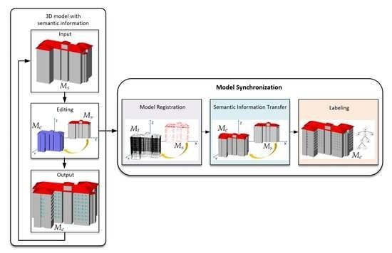
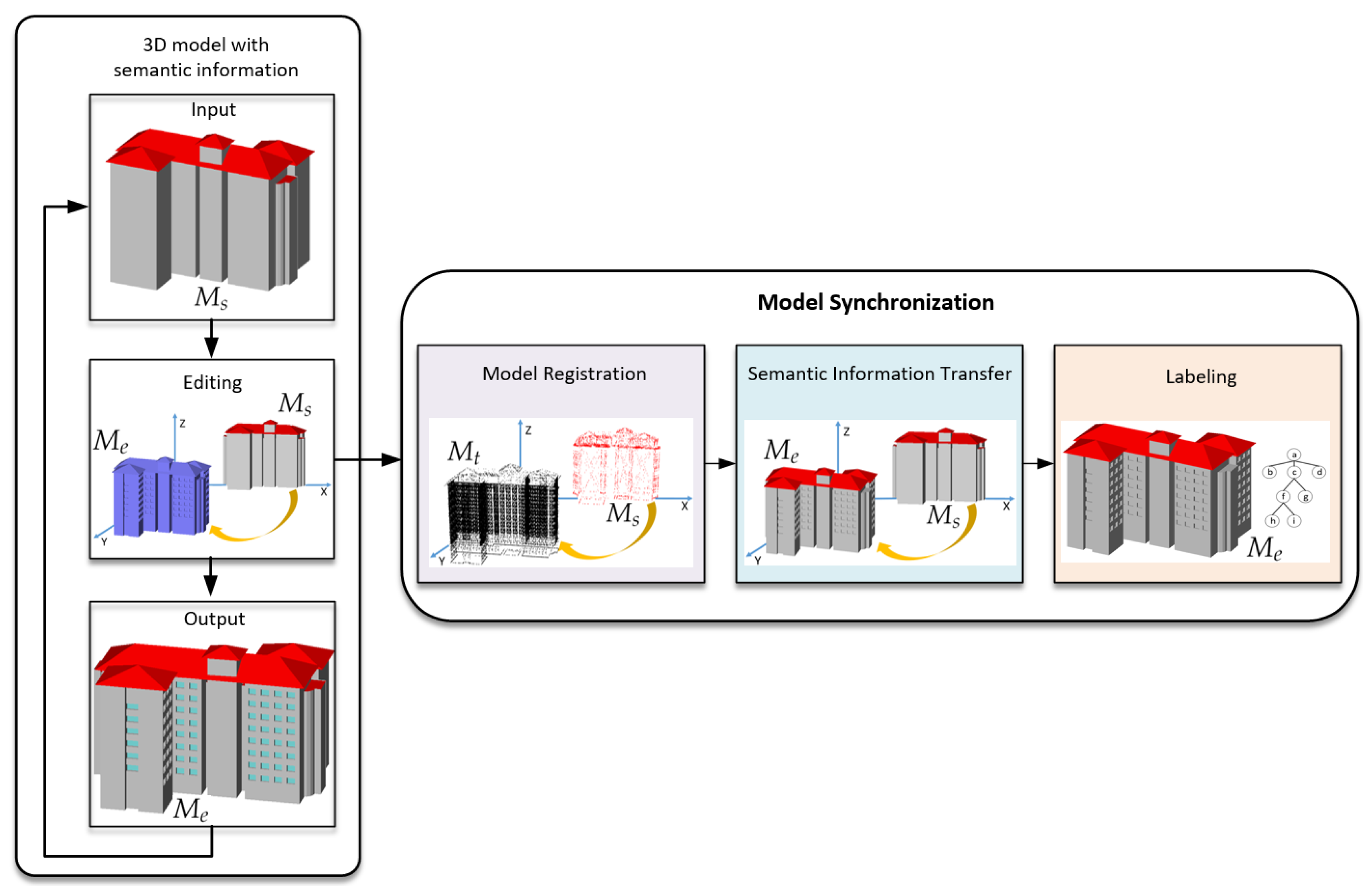
3. Method Overview
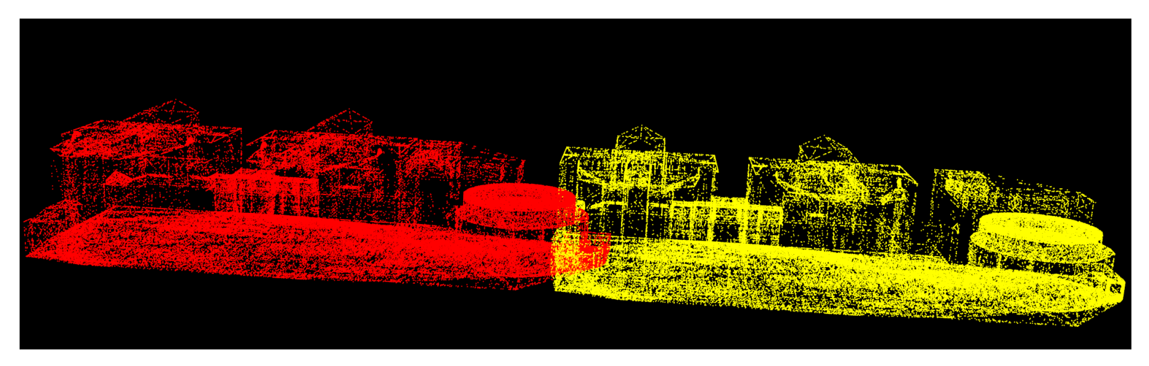
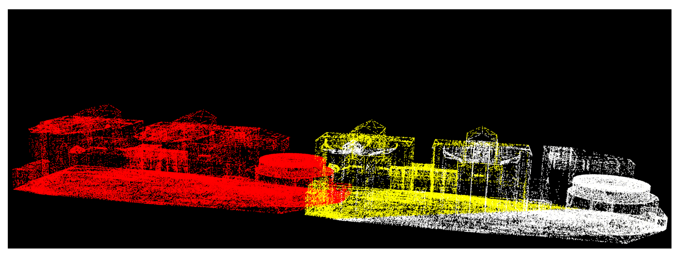
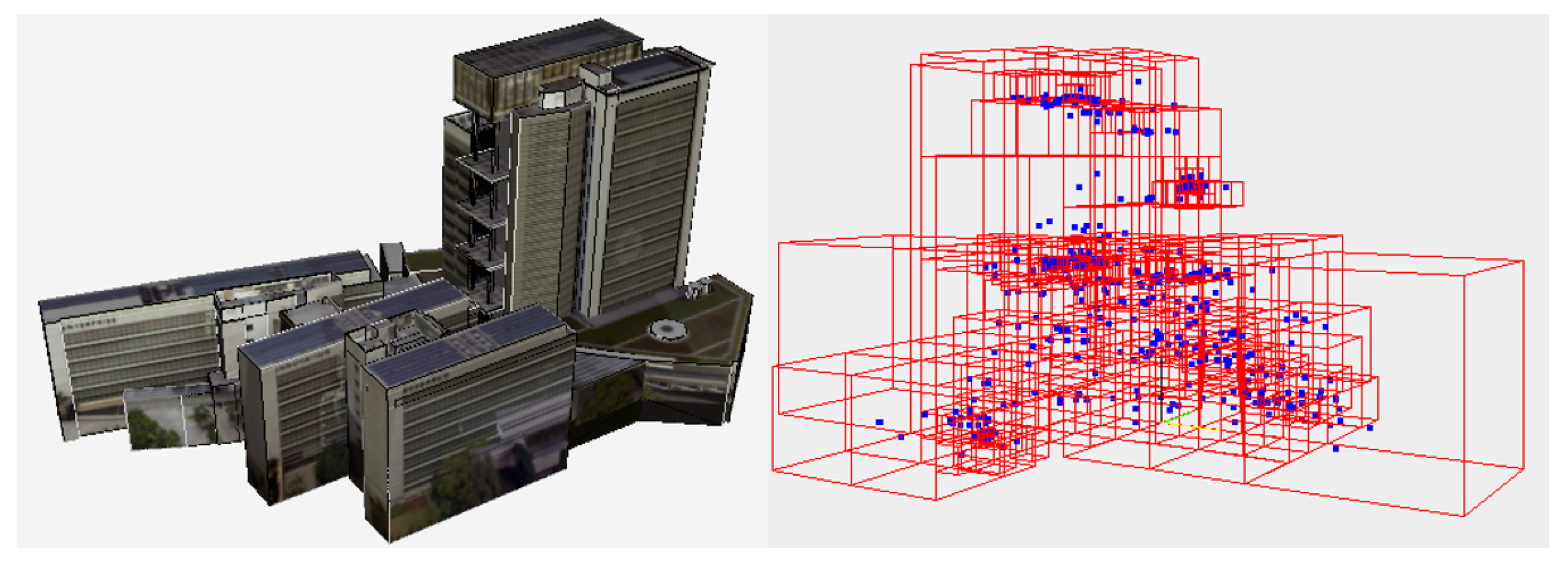
- Model registration: is the source point set for the ICP algorithm, whereas is its target point set. The output of ICP is a transformation matrix which is applied to the source to yield a transformed point set . An octree storing additional information (face normal, face centroid, length of edges) is constructed from the transformed model .
- Semantic information transfer: An octree search with faces from yields matching rigid transformed faces in and their original semantic labels in . Deformed faces are handled in a similar way by an additional UV space search.
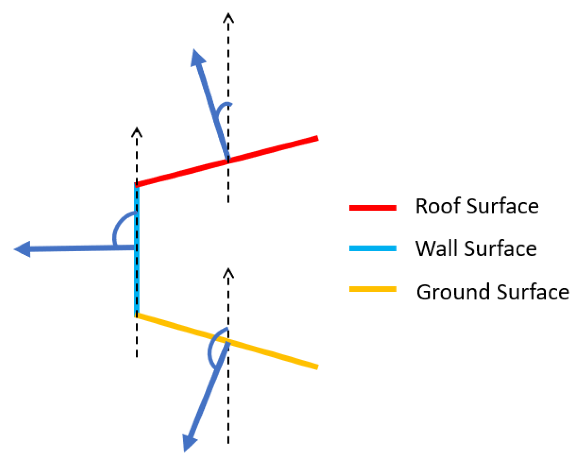
- Labeling: Each face in the edited geometry is incorporated into a topological tree to detect openings and their boundary surfaces. Boundary surfaces are labeled as roof, wall, or ground faces based on their normal direction. For openings, the octree and UV space are used again to find the position in the data model, finally resulting in an updated data model that preserves as much semantic information as possible and which is updated with new faces labeled according to their topology.
3.1. Face Matching
- Face normal .
- Face centroid .
- Length of edges .
- Set of texture coordinates .
- and have same , , and .
- and share same set of texture coordinates.
3.2. Model Registration
3.2.1. ICP Algorithm
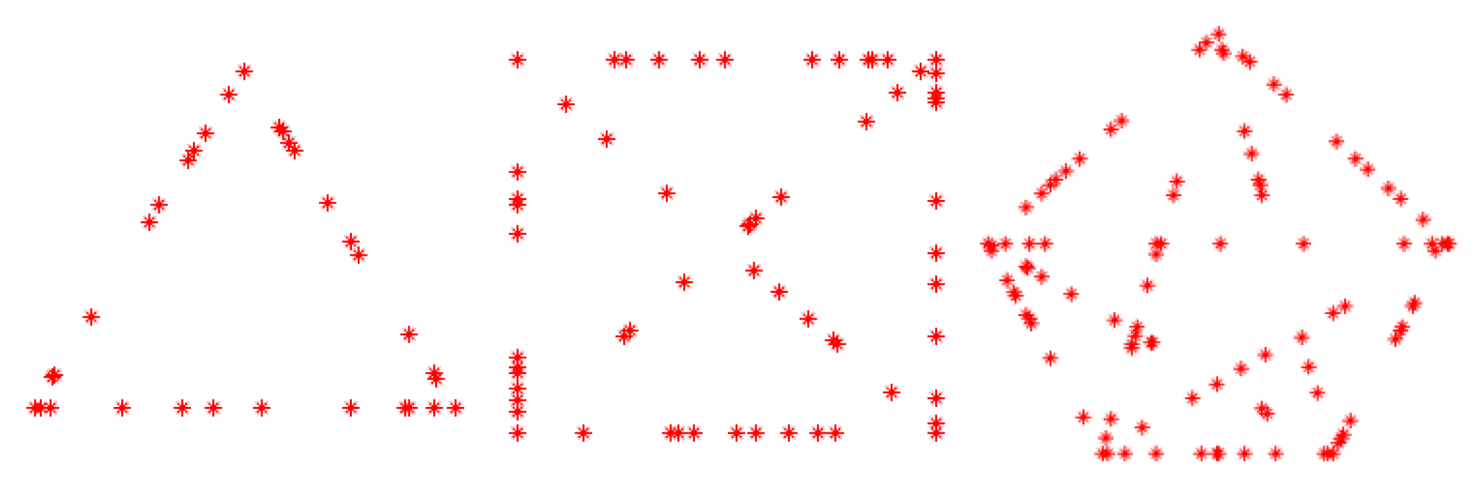
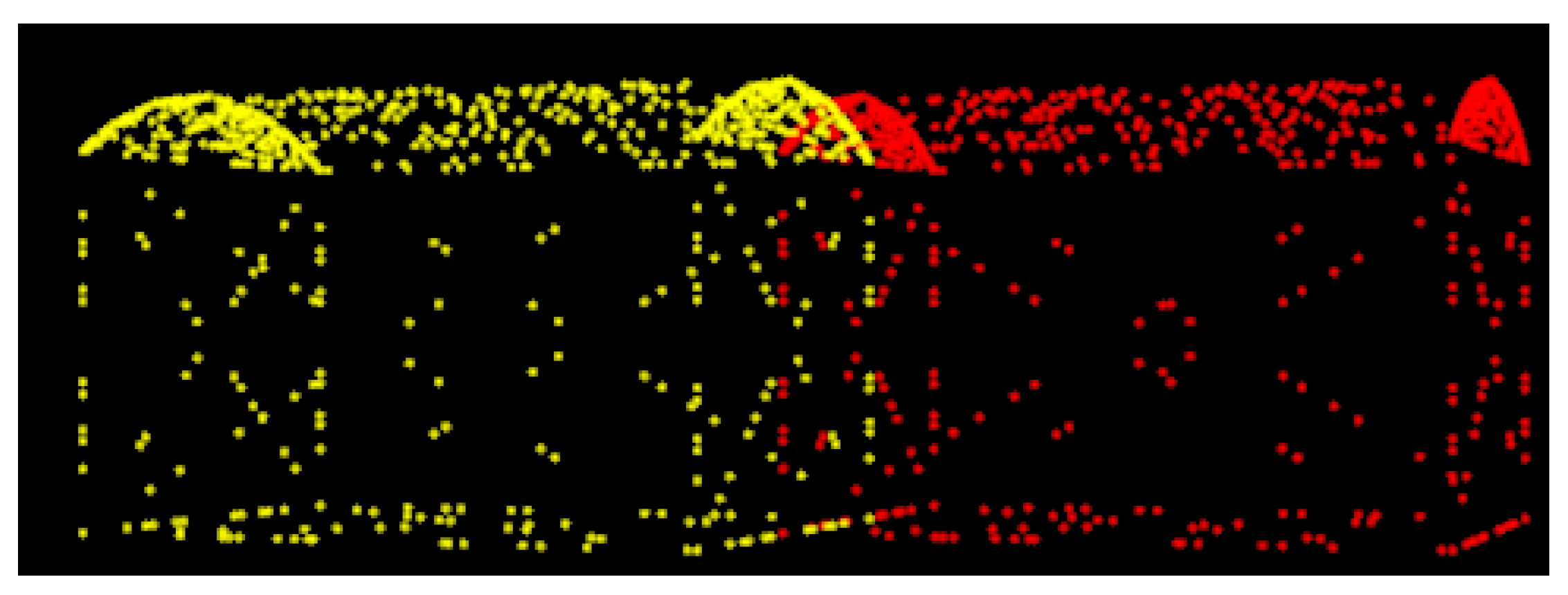
3.2.2. Point Set Generation
- Calculate two random seeds and based on the texture coordinates of and .
- Generate n random numbers based on , and n random numbers based on . By applying these random numbers, we obtain n sampling points and n sampling points (see Equation (4)).
- Add the points obtained by the second step to the source point set and target point set of ICP algorithm.
3.2.3. Parameter Analysis
- Translate 1000 m;
- Translate 10 m;
- Deletion on a face;
- Deformation on a face;
- Push-pull on a face;
- Template application on a face.
3.3. Semantic Information Transfer
3.4. Labeling
4. Discussion
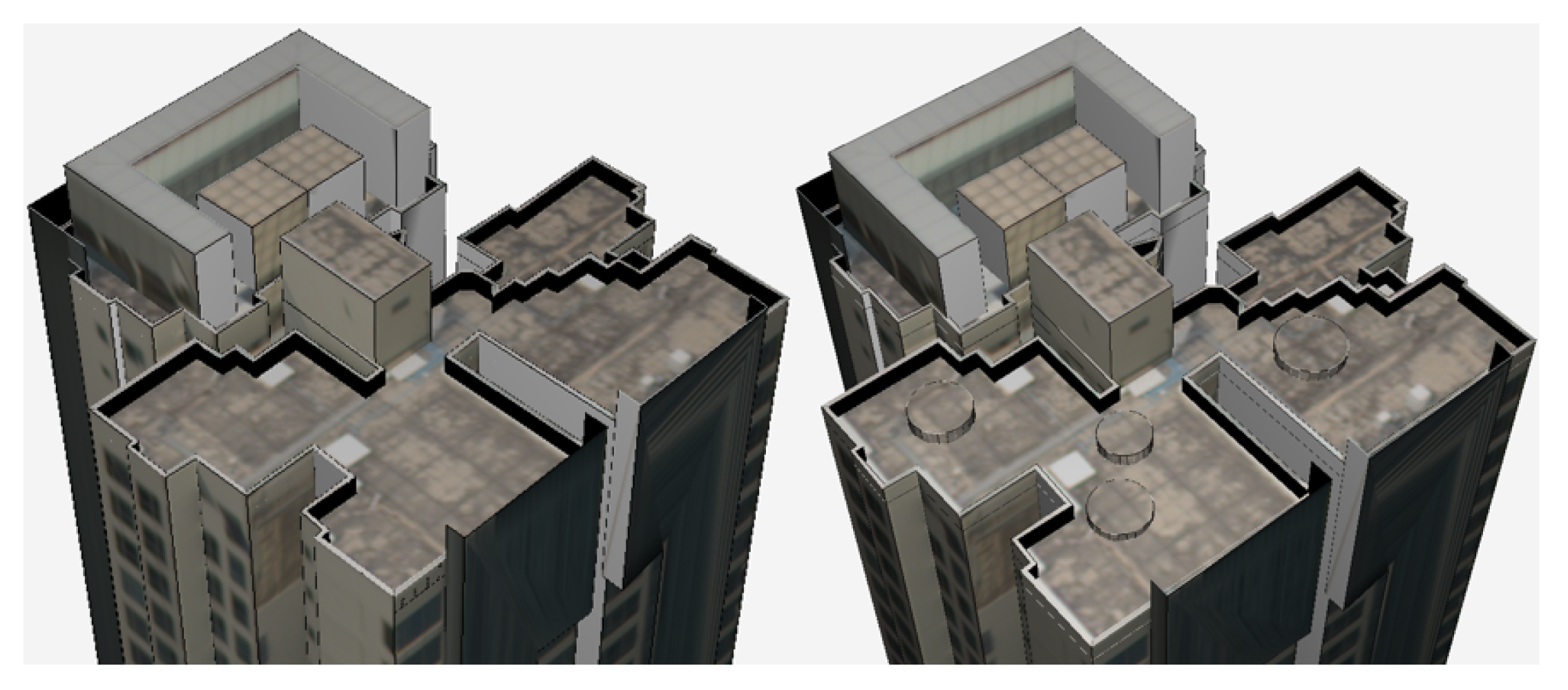
4.1. Face Deletion For Shelters
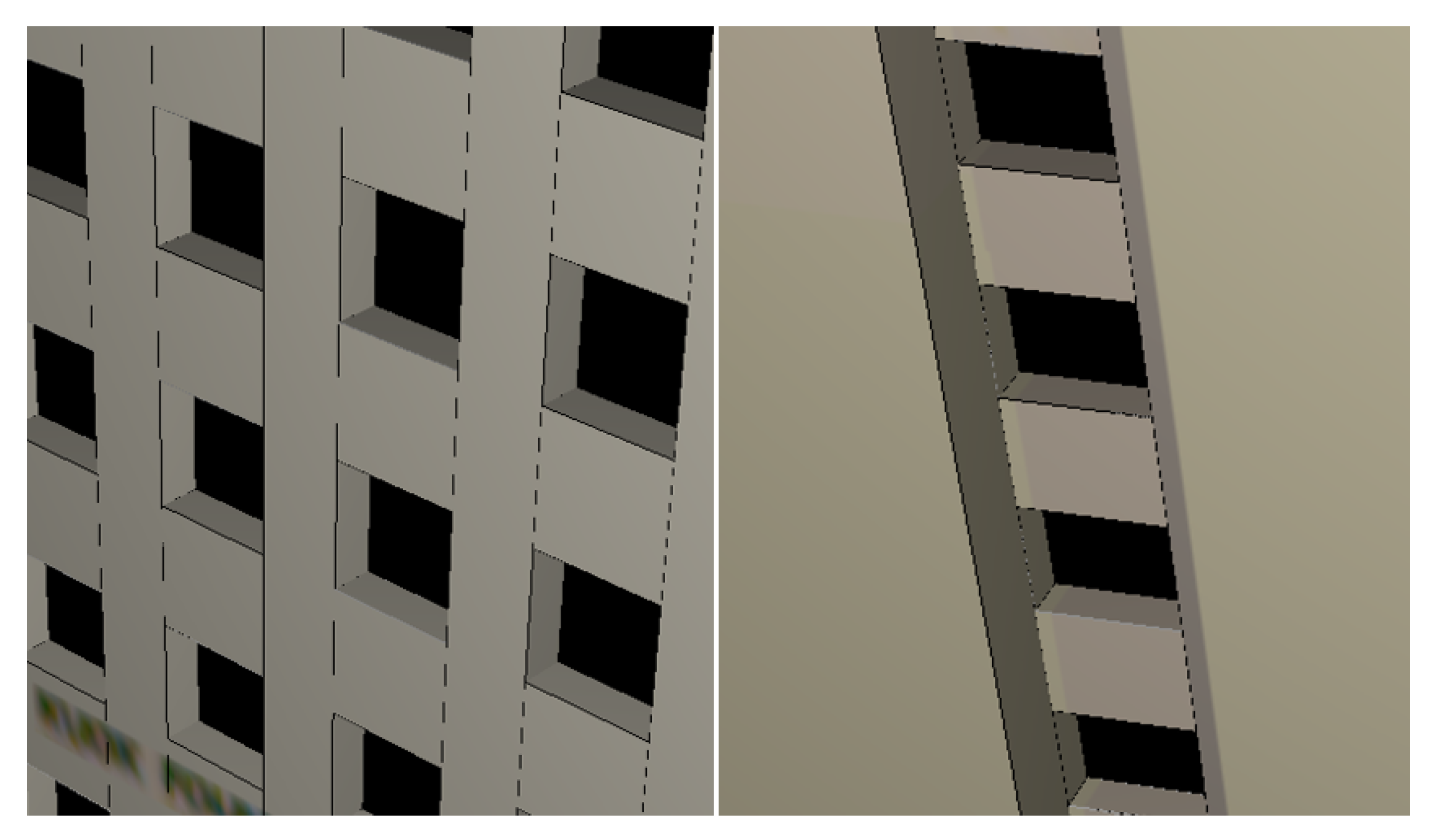
4.2. Template Application For Openings
4.3. Commercial Tools
4.3.1. CityEditor
4.3.2. CityGML Importer
4.3.3. Rhino City
4.3.4. AutoCAD Map 3D
4.3.5. Comparisons among VSE, CityEditor, and CityGML Importer
5. Conclusions
Author Contributions
Funding
Acknowledgments
Conflicts of Interest
References
- Hagedorn, B.; Döllner, J. High-level web service for 3D building information visualization and analysis. In Proceedings of the 15th Annual ACM International Symposium on Advances in Geographic Information Systems, Seattle, WA, USA, 7–9 November 2007. [Google Scholar]
- Psyllidis, A.; Bozzon, A.; Bocconi, S.; Bolivar, C.T. A platform for urban analytics and semantic data integration in city planning. In Proceedings of the International Conference on Computer-Aided Architectural Design Futures, Sao Paulo, Brazil, 8–10 July 2015; Springer: Berlin/Heidelberg, Germany; 2015; pp. 21–36. [Google Scholar]
- Prandi, F.; De Amicis, R.; Piffer, S.; Soave, M.; Cadzow, S.; Boix, E.G.; D’Hondt, E. Using CityGML to deploy smart-city services for urban ecosystems. Int. Arch. Photogramm. Remote Sens. Spat. Inf. Sci. 2013, 4, W1. [Google Scholar] [CrossRef]
- Volpi, M.; Ferrari, V. Structured prediction for urban scene semantic segmentation with geographic context. In Proceedings of the 2015 Joint Urban Remote Sensing Event (JURSE), Lausanne, Switzerland, 30 March–1 April 2015; pp. 1–4. [Google Scholar]
- Kagal, L. A Policy-Based Approach to Governing Autonomous Behavior in Distributed Environments. Ph.D. Thesis, University of Maryland Baltimore County, Baltimore, MD, USA, 2004. [Google Scholar]
- Lipp, M.; Wonka, P.; Müller, P. PushPull++. ACM Trans. Graph. (TOG) 2014, 33, 130. [Google Scholar] [CrossRef]
- TRIMBLE. Sketchup. Available online: www.sketchup.com (accessed on 19 November 2019).
- Parish, Y.I.; Müller, P. Procedural modeling of cities. In Proceedings of the 28th Annual Conference on Computer Graphics and Interactive Techniques, Los Angeles, CA, USA, 12–17 August 2001; pp. 301–308. [Google Scholar]
- Müller, P.; Wonka, P.; Haegler, S.; Ulmer, A.; Van Gool, L. Procedural modeling of buildings. ACM Trans. Graph. (TOG) 2006, 25, 614–623. [Google Scholar] [CrossRef]
- Esri. Procedural Runtime Whitepaper. Available online: https://esri.github.io/esri-cityengine-sdk/html/index.html (accessed on 19 November 2019).
- Alegre, F.; Dellaert, F. A probabilistic approach to the semantic interpretation of building facades. In Proceedings of the CIPA International Workshop on Vision Techniques Applied to the Rehabilitation of City Centres, Lisbonne, Portugal, 25–27 October 2004. [Google Scholar]
- Verdie, Y.; Lafarge, F.; Alliez, P. Lod generation for urban scenes. ACM Trans. Graph. 2015, 34, 30. [Google Scholar] [CrossRef]
- Zhu, Q.; Li, Y.; Hu, H.; Wu, B. Robust point cloud classification based on multi-level semantic relationships for urban scenes. ISPRS J. Photogramm. Remote Sens. 2017, 129, 86–102. [Google Scholar] [CrossRef]
- Wu, C.; Lenz, I.; Saxena, A. Hierarchical Semantic Labeling for Task-Relevant RGB-D Perception. In Proceedings of the 2014 Robotics: Science and Systems Conference, Berkeley, CA, USA, 12–16 July 2014. [Google Scholar]
- Rook, M.; Biljecki, F.; Diakité, A. Towards Automatic Semantic Labelling of 3D City Models. ISPRS Ann. Photogramm. Remote Sens. Spat. Inf. Sci. 2016, 4. [Google Scholar] [CrossRef]
- Sundar, H.; Silver, D.; Gagvani, N.; Dickinson, S. Skeleton based shape matching and retrieval. In Proceedings of the 2003 Shape Modeling International, Seoul, Korea, 12–15 May 2003; pp. 130–139. [Google Scholar]
- Xie, J.; Dai, G.; Zhu, F.; Wong, E.K.; Fang, Y. Deepshape: Deep-learned shape descriptor for 3D shape retrieval. IEEE Trans. Pattern Anal. Mach. Intell. 2016, 39, 1335–1345. [Google Scholar] [CrossRef] [PubMed]
- Besl, P.J.; McKay, N.D. Method for registration of 3-D shapes. Sensor fusion IV: Control paradigms and data structures. Int. Soc. Opt. Photonics 1992, 1611, 586–606. [Google Scholar]
- Zhang, Z. Iterative point matching for registration of free-form curves and surfaces. Int. J. Comput. Vis. 1994, 13, 119–152. [Google Scholar] [CrossRef]
- Rusinkiewicz, S.; Levoy, M. Efficient variants of the ICP algorithm. In Proceedings of the 3rd International Conference on 3D Digital Imaging and Modeling (3DIM 2001), Quebec City, QC, Canada, 28 May–1 June 2001; Volume 1, pp. 145–152. [Google Scholar]
- Fitzgibbon, A.W. Robust registration of 2D and 3D point sets. Image Vis. Comput. 2003, 21, 1145–1153. [Google Scholar] [CrossRef]
- Myronenko, A.; Song, X. Point set registration: Coherent point drift. IEEE Trans. Pattern Anal. Mach. Intell. 2010, 32, 2262–2275. [Google Scholar] [CrossRef] [PubMed]
- Ma, J.; Zhao, J.; Tian, J.; Yuille, A.L.; Tu, Z. Robust point matching via vector field consensus. IEEE Trans. Image Process. 2014, 23, 1706–1721. [Google Scholar] [CrossRef] [PubMed]
- Ge, S.; Fan, G.; Ding, M. Non-rigid point set registration with global-local topology preservation. In Proceedings of the IEEE Conference on Computer Vision and Pattern Recognition Workshops, Columbus, OH, USA, 23–28 June 2014; pp. 245–251. [Google Scholar]
- AUTODESK. Autocad. Available online: http://www.autodesk.com/autocad (accessed on 19 November 2019).
- AUTODESK. Maya. Available online: http://www.autodesk.com/maya (accessed on 19 November 2019).
- Esri. CityEngine. Available online: https://www.esri.com/en-us/arcgis/products/esri-cityengine/overview (accessed on 10 November 2019).
- Esri. ArcGIS Pro. Available online: https://www.esri.com/zh-cn/arcgis/products/arcgis-pro/resources (accessed on 10 November 2019).
- Biljecki, F.; Ledoux, H.; Stoter, J.; Zhao, J. Formalisation of the level of detail in 3D city modelling. Comput. Environ. Urban Syst. 2014, 48, 1–15. [Google Scholar] [CrossRef]
- Kolbe, T.H.; Gröger, G.; Plümer, L. CityGML: Interoperable access to 3D city models. In Geo-Information for Disaster Management; Springer: Berlin, Germany, 2005; pp. 883–899. [Google Scholar]
- BentleySystems. Bentley Map. Available online: https://www.bentley.com/en/products/product-line/asset-performance/opencities-map (accessed on 19 November 2019).
- Bitmanagement. BS Contact Geo. 2019. Available online: http://www.bitmanagement.de/en/products/interactive-3d-clients/bs-contact-geo (accessed on 19 November 2019).
- Fraunhofer Institute for Computer Graphics Research(IGD) CityServer3D. 2019. Available online: http://www.cityserver3d.de/en/ (accessed on 19 November 2019).
- Synthesis, C. CodeSynthesis XSD. 2019. Available online: https://www.codesynthesis.com/ (accessed on 19 November 2019).
- SAFESOOFTWARE. FME. Available online: https://www.safe.com/fme/ (accessed on 10 August 2019).
- 3Dis. CityEditor. Available online: https://www.3dis.de/cityeditor/ (accessed on 19 November 2019).
- UVMSystems. CityGrid. Available online: http://www.uvmsystems.com/index.php/en/ (accessed on 19 November 2019).
- Foley, J.D.; Van, F.D.; Van Dam, A.; Feiner, S.K.; Hughes, J.F.; Hughes, J.; Angel, E. Computer Graphics: Principles and Practice; Addison-Wesley Professional: Boston, MA, USA, 1996; Volume 12110. [Google Scholar]
- Birdal, T.; Ilic, S. A point sampling algorithm for 3d matching of irregular geometries. In Proceedings of the 2017 IEEE/RSJ International Conference on Intelligent Robots and Systems (IROS), Vancouver, BC, Canada, 24–28 September 2017; pp. 6871–6878. [Google Scholar]
- Rodolà, E.; Albarelli, A.; Cremers, D.; Torsello, A. A simple and effective relevance-based point sampling for 3D shapes. Pattern Recognit. Lett. 2015, 59, 41–47. [Google Scholar] [CrossRef]
- DeRose, T.; Meyer, M.; Bakshi, S. Mesh Transfer Using UV-Space. US Patent 8,482,569, 9 July 2013. [Google Scholar]
- Gröger, G.; Kolbe, T.H.; Nagel, C.; Häfele, K.H. OGC City Geography Markup Language (CityGML) Encoding Standard; Open Geospatial Consortium: Wayland, MA, USA, 2012. [Google Scholar]
- Building and Construction Authority. Code of Practice on Buildable Design. Available online: https://www.bca.gov.sg/BuildableDesign/others/copbddec00.pdf (accessed on 19 November 2019).
- PCL. Point Cloud Library. Available online: http://pointclouds.org/contact.html (accessed on 19 November 2019).
- KIT. FZKViewer. Available online: https://www.iai.kit.edu/1302.php (accessed on 10 August 2019).
- SafeSoftware. CityGML Importer. Available online: https://www.safe.com/citygml-importer (accessed on 19 November 2019).
- Autodesk. InfraWorks. Available online: https://www.autodesk.com/products/infraworks/overview (accessed on 19 November 2019).
- AUTODESK. AutoCAD Map 3D. Available online: https://knowledge.autodesk.com/support/autocad-map-3d (accessed on 19 November 2019).
- Associates, R.M. Rhino 3D. Available online: https://www.rhino3d.com/ (accessed on 19 November 2019).
- RhinoTerrain. RhinoCity. 2019. Available online: https://www.rhinoterrain.com/en/rhinocity.html (accessed on 19 November 2019).


| Editing Type | Editing Operation | ID |
|---|---|---|
| Transformation | Translate the entire model | 01 |
| Rotate the entire model | 02 | |
| Deletion | Delete single vertex | 03 |
| Delete multiple vertices | 04 | |
| Delete edge between two non-planar faces | 05 | |
| Delete edge between two co-planar faces | 06 | |
| Delete face with holes | 07 | |
| Delete face without holes | 08 | |
| Delete face with child faces | 09 | |
| Delete face without child faces | 10 | |
| Deformation | Move single vertices | 11 |
| Move multiple vertices | 12 | |
| Move single edge | 13 | |
| Move multiple edges | 14 | |
| Move single face | 15 | |
| Move multiple faces | 16 | |
| Move arbitrary selection of faces/edges/vertices | 17 | |
| Push-pull | Push-pull of existing face follow the face normal | 18 |
| Push-pull on existing face with an angle | 19 | |
| Push-pull on existing face in corner vertically | 20 | |
| Push-pull on existing face in corner with an angle | 21 | |
| Push-pull on existing edge | 22 | |
| Push-pull after creation of a face on an existing face | 23 | |
| Push-pull after creation of a edge on an existing face | 24 | |
| Push-pull after creation of multiple face on an existing face | 25 | |
| Push-pull after creation of multiple face on multiple existing face | 26 | |
| Push-pull after creation of a face on an existing face with holes | 27 | |
| Push-pull after creation of a circle on an existing face | 28 | |
| Template | Apply procedural templates with one level of opening extrusion | 29 |
| Apply procedural templates with two levels of opening extrusion | 30 |
| Test Case ID | VSE (Clicks) | CityEditor (Clicks) | CityGML Importer (Clicks) |
|---|---|---|---|
| Initialization | 0 | 90 | 1 |
| 01 | 1 | 0 | 0 |
| 02 | 1 | 0 | 0 |
| 05 | 1 | 0 | 0 |
| 08 | 1 | 0 | 0 |
| 10 | 1 | 0 | 0 |
| 13 | 1 | 0 | 0 |
| 14 | 1 | 0 | 0 |
| 15 | 1 | 0 | 0 |
| 16 | 1 | 0 | 0 |
| 18 | 1 | 4 | 4 |
| 20 | 1 | 4 | 4 |
| 23 | 1 | 10 | 10 |
| 25 | 1 | 20 | 20 |
| 26 | 1 | 20 | 20 |
© 2020 by the authors. Licensee MDPI, Basel, Switzerland. This article is an open access article distributed under the terms and conditions of the Creative Commons Attribution (CC BY) license (http://creativecommons.org/licenses/by/4.0/).
Share and Cite
Yao, S.; Ling, X.; Nueesch, F.; Schrotter, G.; Schubiger, S.; Fang, Z.; Ma, L.; Tian, Z. Maintaining Semantic Information across Generic 3D Model Editing Operations. Remote Sens. 2020, 12, 335. https://doi.org/10.3390/rs12020335
Yao S, Ling X, Nueesch F, Schrotter G, Schubiger S, Fang Z, Ma L, Tian Z. Maintaining Semantic Information across Generic 3D Model Editing Operations. Remote Sensing. 2020; 12(2):335. https://doi.org/10.3390/rs12020335
Chicago/Turabian StyleYao, Sidan, Xiao Ling, Fiona Nueesch, Gerhard Schrotter, Simon Schubiger, Zheng Fang, Long Ma, and Zhen Tian. 2020. "Maintaining Semantic Information across Generic 3D Model Editing Operations" Remote Sensing 12, no. 2: 335. https://doi.org/10.3390/rs12020335
APA StyleYao, S., Ling, X., Nueesch, F., Schrotter, G., Schubiger, S., Fang, Z., Ma, L., & Tian, Z. (2020). Maintaining Semantic Information across Generic 3D Model Editing Operations. Remote Sensing, 12(2), 335. https://doi.org/10.3390/rs12020335