Article

Rheology of the Zagros Lithosphere from Post-Seismic Deformation of the 2017 Mw7.3 Kermanshah, Iraq, Earthquake

1
Aerospace Information Research Institute, Chinese Academy of Sciences, Beijing 100094, China
2
University of Chinese Academy of Sciences, Beijing 100049, China
3
Rosenstiel School of Marine and Atmospheric Sciences, University of Miami, Miami, FL 33149, USA
4
Laboratory of Target Microwave Properties (LAMP), Zhongke Academy of Satellite Application in Deqing (DASA), Deqing 313200, China
*
Author to whom correspondence should be addressed.
Remote Sens. 2020, 12(12), 2032; https://doi.org/10.3390/rs12122032
Submission received: 26 May 2020 / Revised: 23 June 2020 / Accepted: 23 June 2020 / Published: 24 June 2020
(This article belongs to the Special Issue Remote Sensing in Applied Geophysics)

Abstract

:
We use 2018–2020 Sentinel-1 InSAR time series data to study post-seismic deformation processes following the 2017 Mw 7.3 Kermanshah, Iraq earthquake. We remove displacements caused by two large aftershock sequences from the displacement field. We find that for a six month period the response is dominated by afterslip along the up-dip extension of the coseismic rupture zone, producing up to 6 cm of radar line-of-sight displacements. The moment magnitude of afterslip is Mw 5.9 or 12% of the mainshock moment. After that period, the displacement field is best explained by viscoelastic relaxation and a lower crustal viscosity of η l c = 1 0.4 + 0.8 × 10 19   Pas . The viscosity of the uppermost mantle is not constrained by the data, except that it is larger than 0.6 × 10 19   Pas . The relatively high lower crustal and uppermost mantle viscosities are consistent with a cold and dry lithosphere of the Zagros region.

Graphical Abstract

1. Introduction

The Mw 7.3 Kermanshah earthquake of 12 November 2017 near the Iran/Iraq boundary occurred along a thrust fault of the Zagros Mountains. It killed more than 400 people and destroyed 12,000 buildings. There were serious economic losses caused by this event [1]. It was one of the largest earthquakes in the northwestern Zagros during the instrumental era (others were the 1909 Mw 7.3 earthquake and 1957 Mw 7.1 earthquake) [2,3]. Observations of post-seismic deformation provide an opportunity to investigate the fault and rheological properties of the Zagros lithosphere.
Post-seismic displacements can be caused by (i) afterslip along the fault, either along the patch that ruptured during the earthquake or next to it [4,5,6,7]; (ii) viscoelastic relaxation of the lower crust and/or upper mantle [8,9,10]; (iii) poroelastic rebound following earthquake-induced pore-fluid pressure changes [11,12,13]; or (iv) large aftershocks. These processes have different spatial-temporal characteristics [14]. Afterslip and poroelastic rebound cause ground displacements in the near field and last for a few months to years. In contrast, viscoelastic relaxation causes displacements in the far field and can last several decades. Understanding the origin of post-seismic deformation is important for seismic hazard because it changes the crustal stress field, loading or unloading nearby faults [15,16,17].
In this study we use 2.3 years (until February 2020) of Sentinel-1 data to investigate post-seismic displacements after the Kermanshah earthquake. After removing the coseismic deformation of the largest aftershocks, we investigate whether surface displacements reflect afterslip and/or viscoelastic relaxation and explore the afterslip characteristics and the lithospheric rheology of this region.

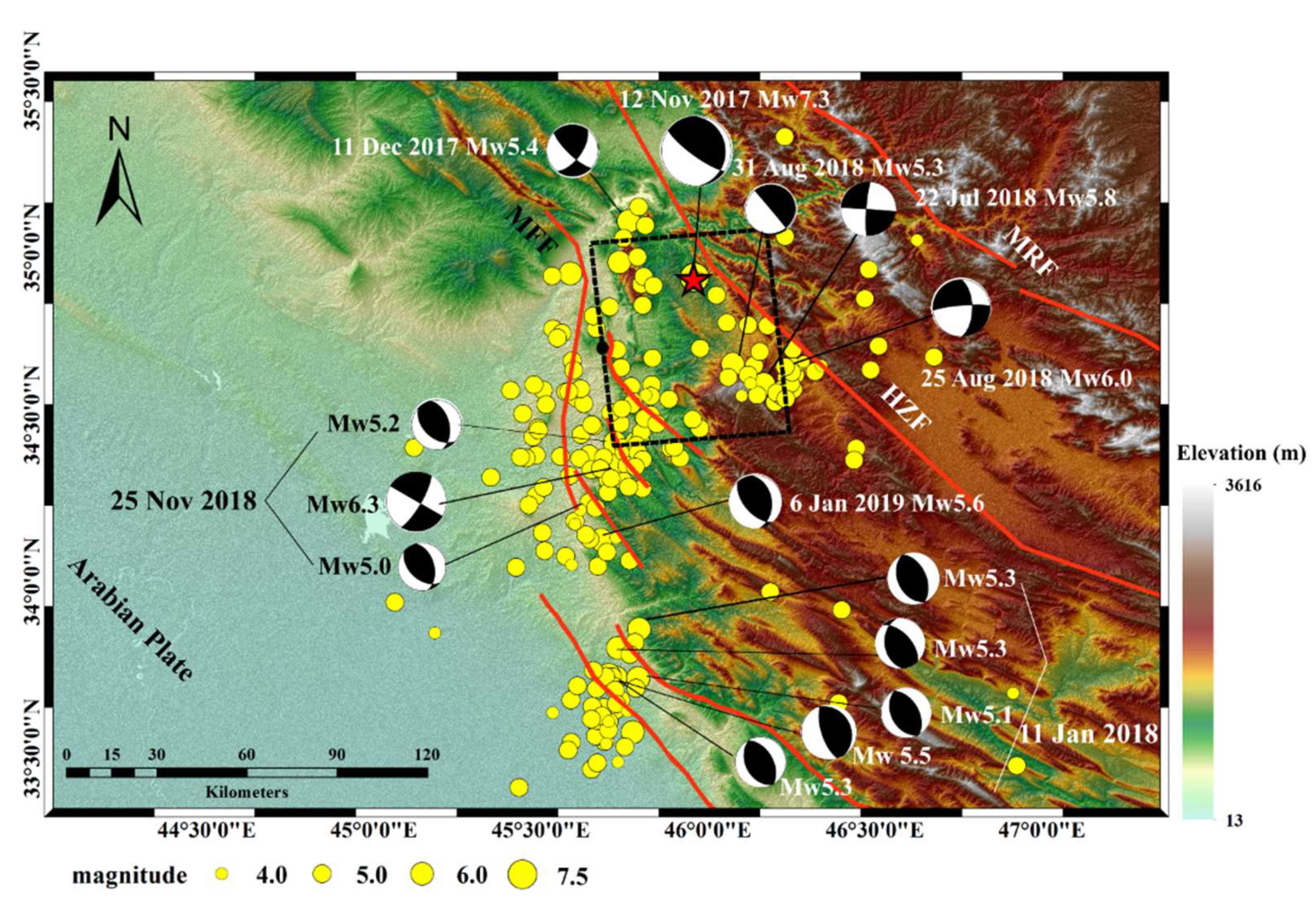
2. Geologic Setting and Aftershock Sequence

The Kermanshah earthquake is located on the southwestern edge of the northwestern Zagros fold-and-thrust belt (ZFTB), one of the most seismically active intra-continental belts and relatively young orogens in the world [8,18]. ZFTB is formed due to continental collision between the Arabian and Eurasian plates in western Asia. The convergence rate between these two plates is approximately ~2 cm/year [19] and ZFTB accommodates one third of the total collision rate, according to the NUVEL-1A plate motion model [20]. GPS data show that the collision rate decreases steadily from 9 mm/year in the southeastern section to 7 mm/year and 4 mm/year in the central and northwestern Zagros, respectively [20]. The Zagros Main Recent Fault (MRF), the High Zagros Fault (HZF) and the Zagros Mountain Front Fault (MFF) are major faults in the northwestern Zagros region (Figure 1).
Several studies using seismic and geodetic data concluded that this earthquake occurred on a shallowly east-dipping blind fault with 15° dip angle and between 13 and 20 km depth [3,18,20,21,22,23,24]. For the viscoelastic relaxation simulation below we use the source parameters of Vajedian [3].
The Kermanshah earthquake was followed by strong aftershock sequences. There were two sequences of aftershocks with several events with magnitude 5.0 or larger that occurred in close vicinity within a short time period. The first one was a one-hour-long sequence on 11 January 2018 with magnitude ranging from Mw 5.1 to Mw 5.5; the second one was a seven-hour-long sequence on 25 November 2018 with magnitude ranging from Mw 5.0 to Mw 6.3. These sequences (Figure 1, Table 1) are referred to as aftershock sequence 1 and 2, respectively. The third largest aftershock was an Mw 6.0 on 25 August 2018.

3. InSAR Data and Processing Methodology

We used a total of 134 ascending Sentinel-1 A/B data from Path 72 (from 17 November 2017 to 5 February 2020; the first image 5 days after the mainshock) and 54 descending images from Path 79 (from 18 November 2017 to 31 January 2020; the first image 6 days after the mainshock).
We used ISCE stack processor [25,26] to generate the interferograms with 21 looks in the azimuth and 7 looks in the range direction. Precise orbit data and the 3 arc-second DEM from the Shuttle Radar Topography Mission (SRTM) [27] were used to simulate and remove the phase error caused by topography and earth curvature from each interferogram. Multi-looked and filtered interferograms were registered to a master SAR image by finding offsets between single-look complex (SLC) images and the master SLC using DEM and orbit vectors. Finally, the phases of the coregistered interferograms were unwrapped using the statistical-cost network-flow algorithm (SNAPHU) [28].
For time series processing we used the routine workflow of the Miami InSAR time series software in Python (MintPy) [29]. In this workflow the network of interferograms was inverted for the raw phase time series and then corrected for the tropospheric delay (we used the ERA5 global atmospheric model) and topographic residuals to obtain the noise-reduced displacement time series from which the average line of sight (LOS) velocity was estimated pixel by pixel.

4. Modelling Approach

To estimate the aftershock and afterslip parameters, we consider uniform rectangular dislocations in a homogeneous elastic half-space [30]. The model parameters are fault location, length, width, dip angle, strike angle, depth, strike slip and dip slip. To estimate the rheological structure we consider Maxwell rheology for the lower crust and upper mantle, each characterized by two parameters, the steady state shear modulus and steady state viscosity. We use the RELAX software [31,32,33], which uses the Fourier–domain elastic Green’s functions and the equivalent body-force representation of coseismic and post-seismic deformation processes to calculate the viscoelastic relaxation displacement. The model parameters are the lower crust and upper mantle viscosities.
We sample from the data using a downsampling method combining uniform and quadtree sampling. We use quadtree sampling in the region with significant deformation and in the far field the uniform sampling approach (see Supplemental Material for downsampling results). We calculate for each model a misfit function χ 2 defined as:
χ 2 = ( d obs d sim ) C 1 ( d obs d sim ) 1
where d obs and d sim are the observed and simulated displacements, respectively, and C is the covariance matrix [34]. We solve the non-linear inversion problem for the elastic dislocations using a Bayesian approach with the Geodetic Bayesian Inversion Software (GBIS) [34]. We also use GBIS to estimate C. We invert for the rheological structure using a grid search approach.

5. Results

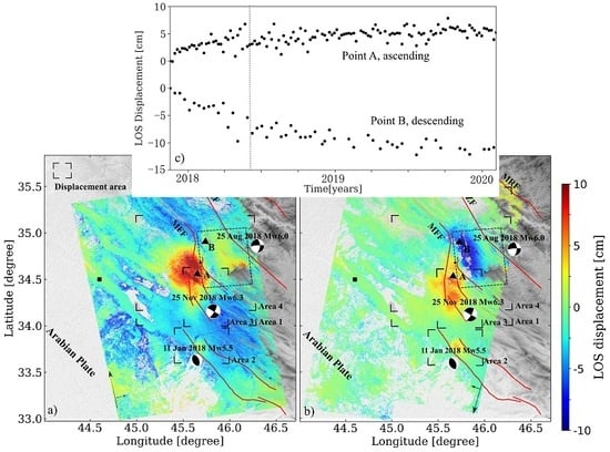
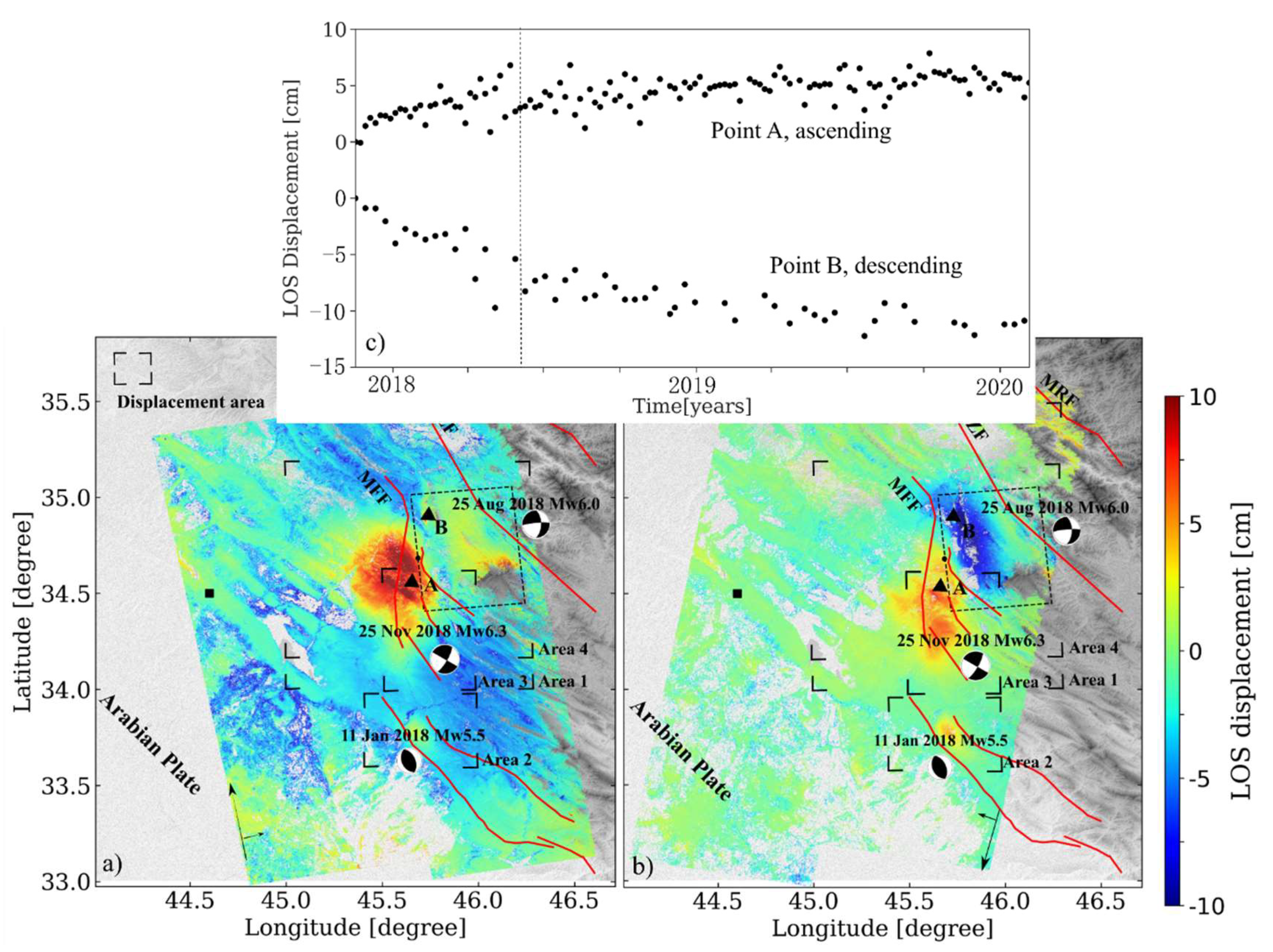
5.1. Post-Seismic Displacement Field

Figure 2 shows the line-of-sight (LOS) displacements from ascending and descending orbits after the earthquake (17 and 18 November 2017, respectively) to February 2020, where the positive value means movement towards the sensors and negative values mean movement away from the sensor. The ascending data shows a lobe of up to 8 cm of LOS decrease (yellow/red color) and the descending data shows lobes of both LOS decrease and LOS increase (up to 10 cm, blue color). The ascending and descending displacement time series for points in the epicentral area show initially rapidly and then slowly growing and decaying signals, respectively (Figure 2c). We therefore consider two time periods characterized by different displacement patterns, from 17 November 2017 to 10 June 2018 (time period 1) and from 10 June 2018 to February 2020 (time period 2). We consider four different areas (Figure 2a,b). In addition to the area used for studying viscoelastic relaxation (area 1), we consider two aftershock areas (areas 2 and 3) and an area to investigate afterslip (area 4).

5.2. Aftershocks

We consider both aftershock sequences as composite events and we obtain elastic dislocation models for aftershock sequence 1 and 2 so that their contributions can be removed from the post-seismic displacement fields. We do not consider the 25 August 2018 aftershock located east of the epicenter because there is no clear signal associated with it in ascending and descending data (Figure S1) and no geodetic focal mechanism can be estimated. For both ascending and descending orbits, we use interfergrams reconstructed from the raw time series. They are less noisy than the observed interferograms because the network inversion of interferograms filters out temporal decorrelation noise.
For aftershock sequence 1, the best-fitting dislocation has a length and width of 12.9 km and 5.4 km and 0.4 m slip. For aftershock sequence 2, the best-fitting dislocation has a length and width of 12.7 km and 8.8 km and 1.8 m slip (Table 2). The observations, modelled displacement and difference between observations and model are shown in Figure 3a,b. The red lines are nearby faults. The geodetic focal mechanisms (shown in Figure 3) are very similar to the Centroid-Moment-Tensor (CMT) solutions (shown in Figure 1).

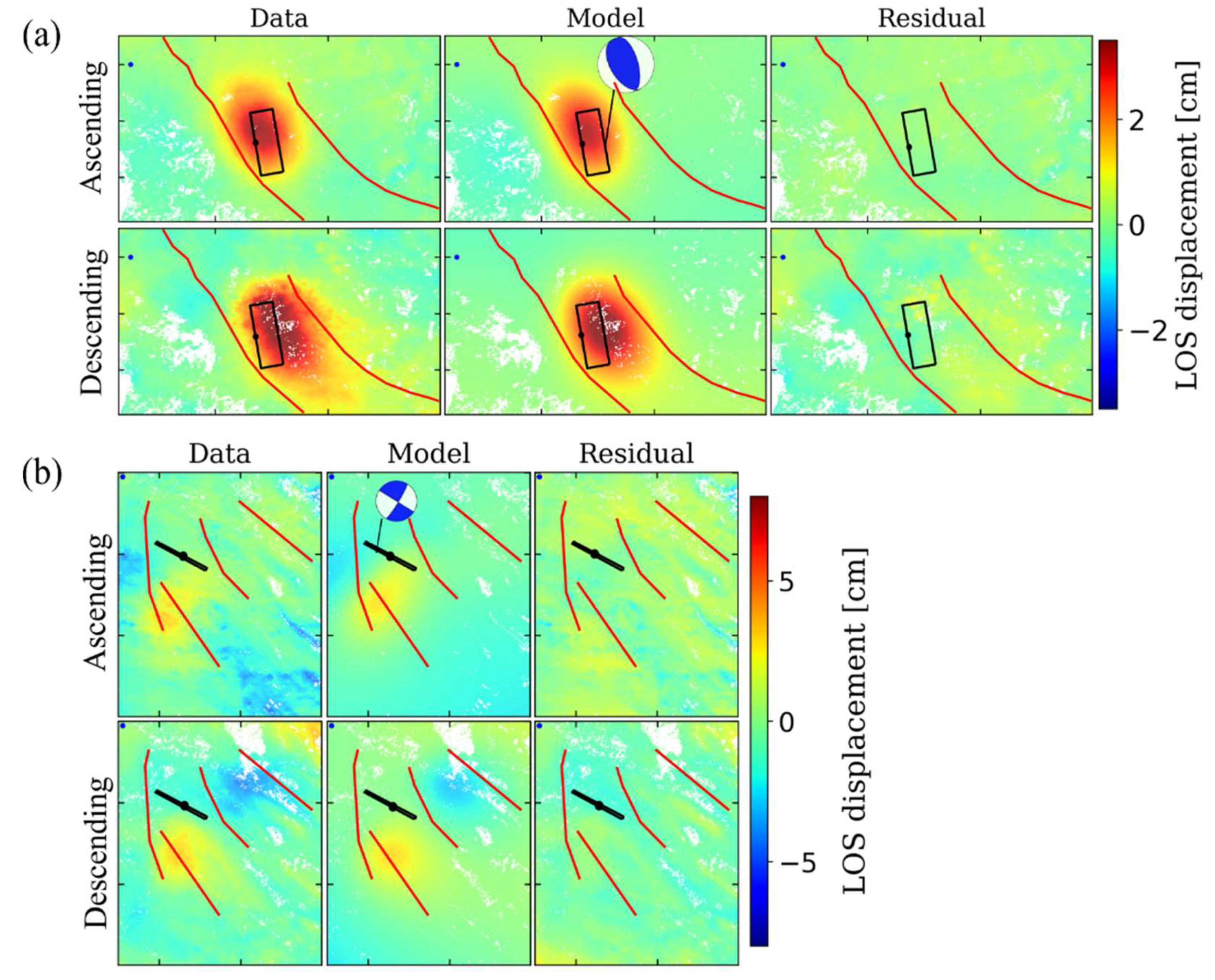
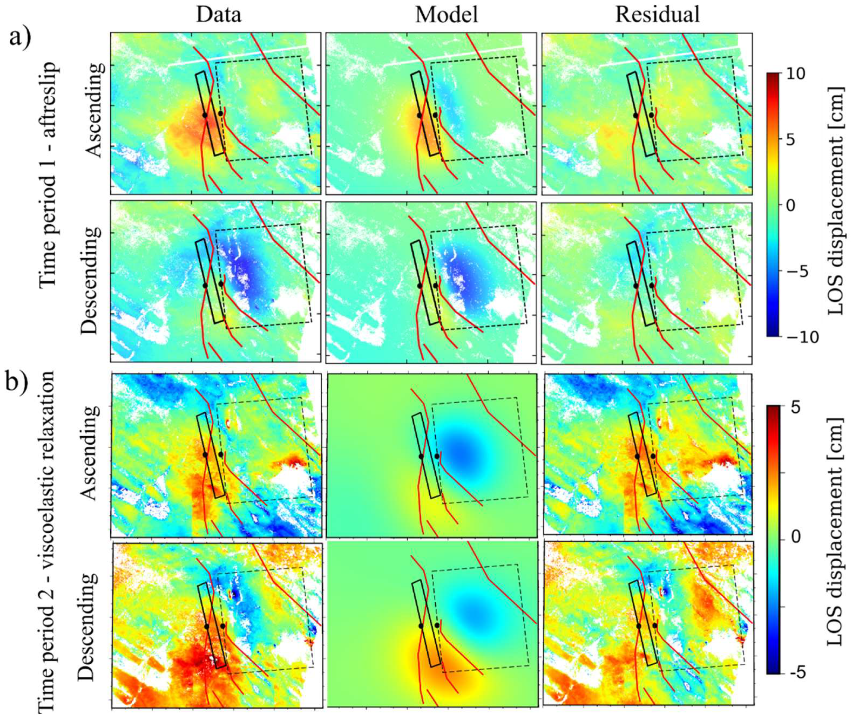
5.3. Afterslip for Time Period 1

To test whether the surface displacements are consistent with afterslip, we use the ascending and descending data until June 2018 (Figure 4a) after removal of the contribution from the January 2018 aftershock sequence. We estimate the best-fitting uniform dislocation using a homogeneous elastic half space model. The best-fitting solution (Table 2, black solid rectangle in Figure 4a) shows that the observations are well explained by 0.8 m of uniform slip along one dislocation with a length and width of 45.5 and 6.4 km located on the near-horizontal, western, up-dip continuation of the coseismic fault.

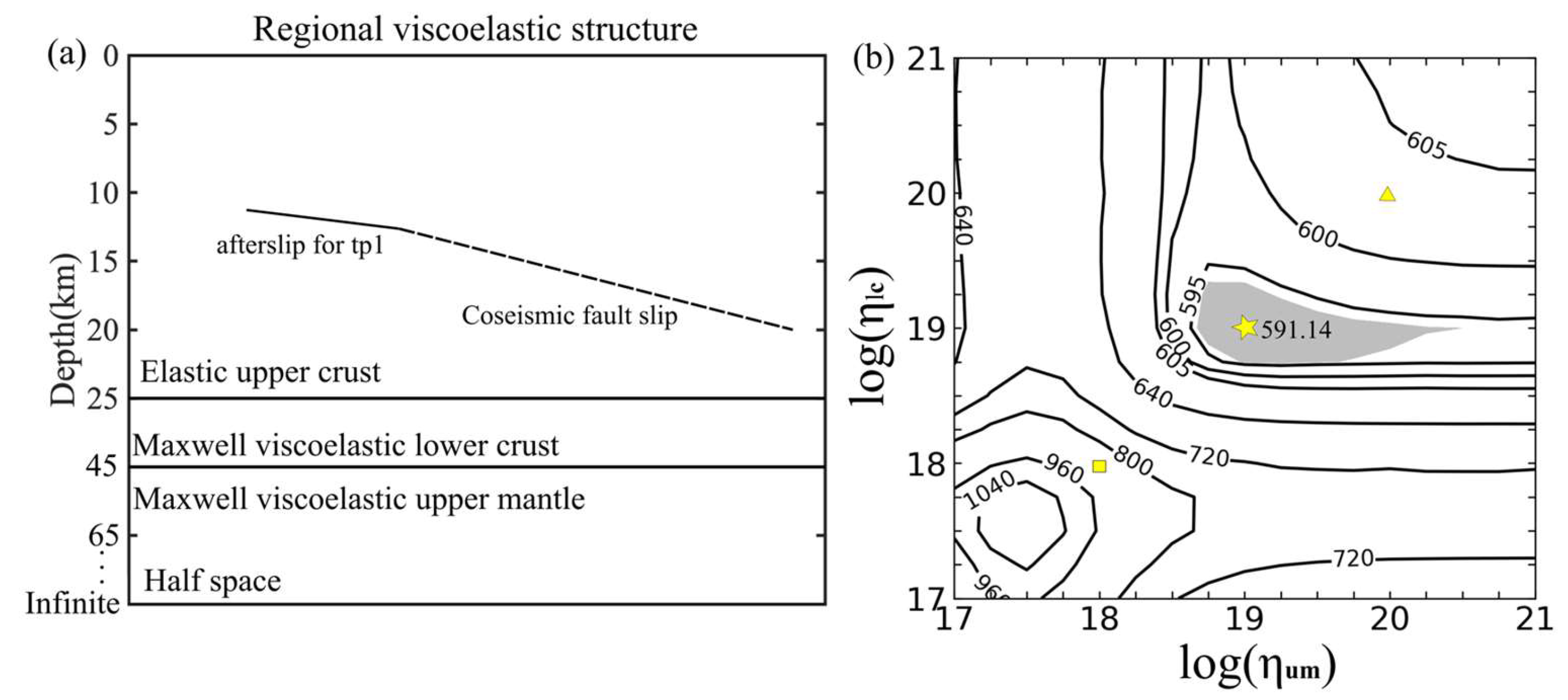
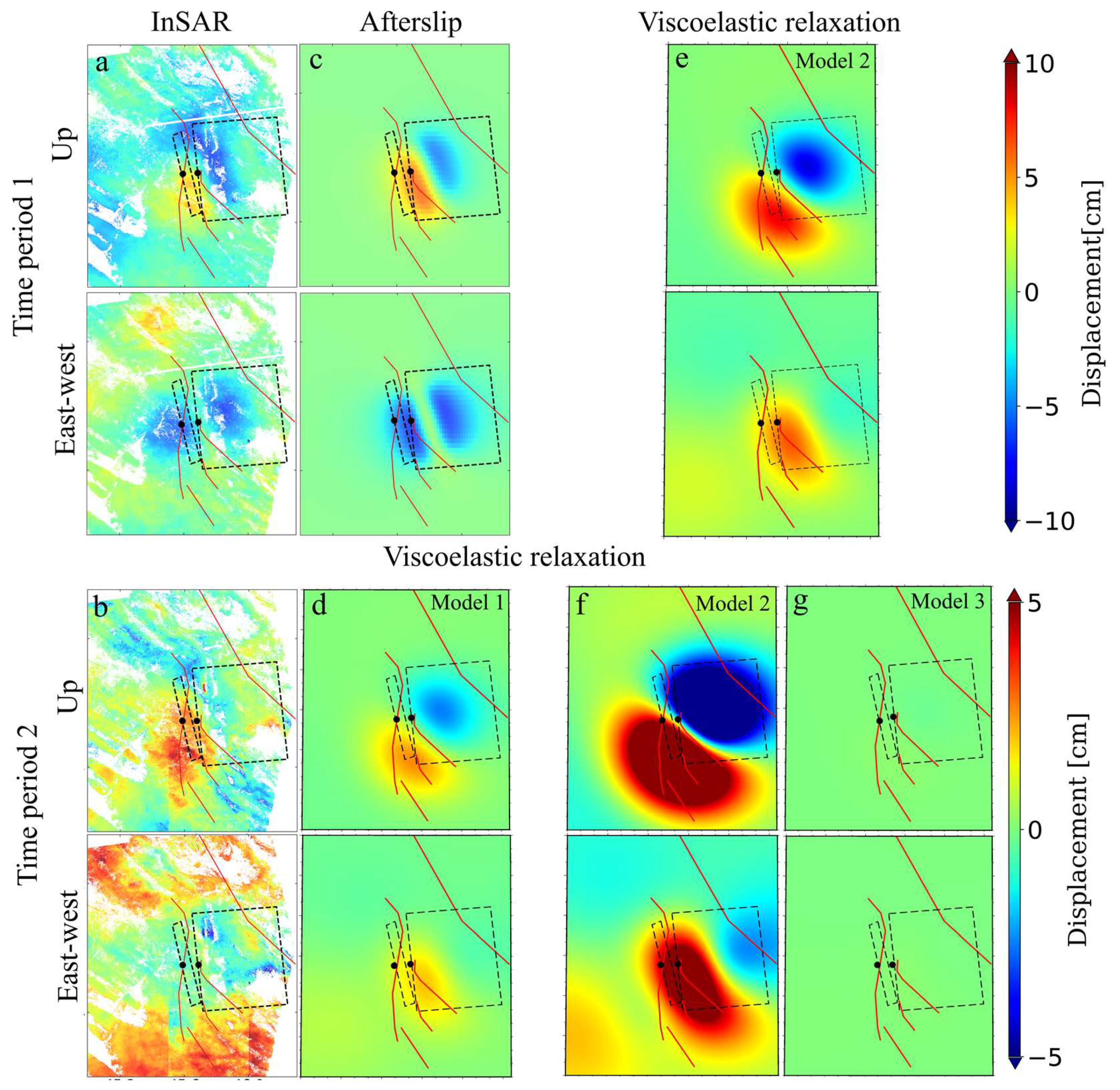
5.4. Viscoelastic Relaxation for Time Period 2

We assume that the displacements in time period 2 are caused by viscoelastic relaxation. In order to constrain the rheological structure we use a 25 km-thick elastic upper crust and a 20 km-thick viscoelastic Maxwell lower crust over a viscoelastic Maxwell upper mantle (Figure 5a; the average depth of the regional Moho is 45 km according to the CRUST 1.0 model) [35,36]. In the grid search the viscosities of the lower crust and upper mantle range from 1 × 10 17   Pas to 1 × 10 21   Pas ; we use a step size for the logarithm of viscosity of 0.25.
Our result (Figure 5b) yields the best estimates of the parameters η l c = 1 0.4 + 0.8 × 10 19   Pas , where the confidence interval is calculated using F–Test [37,38,39]. Our data resolve the viscosity of the lower crust but not the viscosity of the uppermost mantle, except that it is larger than 0.6 × 10 19   Pas .
The comparison between the observed and simulated displacement (Figure 4b) shows that the model explains the descending data well but there is a discrepancy for the ascending data. This discrepancy can be attributed to the larger tropospheric noise for the ascending data which are acquired during the day when the tropospheric variability is high (local acquisition time of 15:00 and 3:00 for ascending and descending data, respectively). What is more, the color discontinuity in the ascending data (around center-bottom of Figure 4b, top) is caused by the subtraction of coseismic displacement of aftershock sequence 2.
Furthermore, the viscoelastic relaxation signal during this 1.75 year period is relatively small (up to 4 cm). The small signal is a consequence of the fault geometry. A horizontal fault causes largely horizontal flow.
We also explored afterslip models and concluded that they can be ruled out. The fault plane of the best-fitting model locates a few kilometers above the coseismic rupture in the phanerozoic cover (Figures S2 and S3), which is geologically not plausible. Besides, the best-fitting viscoelastic relaxation model is characterized by a significantly better rms ( r m s = i = 1 n r e s i d u a l i 2 n ) than the best-fitting afterslip model (0.015 m versus 0.025 m). We can also rule out afterslip on the coseismic rupture or its downdip extension because of even higher rms. We did not consider combined models with both afterslip and viscoelastic relaxation because the data lack the resolution to constrain all model parameters.

5.5. Summary of Post-Seismic Models

To visualize the fits of the post-seismic models we combine the ascending and descending displacement fields for the two time periods to the quasi-vertical and quasi-horizontal displacements in east–west direction [40] (Figure 6a,b). The north–south displacement cannot be calculated because only right-looking InSAR data are available and because polar-orbiting sensors are not sensitive to north–south displacements. We generate simulations for models with lower and higher viscosities in both the lower crust and uppermost mantle. We use η l c = η u m = 10 18   Pas for the low viscosity model (model 2) and η l c = η u m = 10 20   Pas for the high viscosity model (model 3), respectively.
For time period 1, the low viscosity model produces vertical displacements comparable to the observations, but the east–west displacements are different than observed (model 2, Figure 6a). This reinforces that afterslip was the dominating process during this period. For time period 2, the low and high viscosity models predict significantly more and less displacements than observed, respectively (models 2, 3 in Figure 6f,g), reinforcing that the viscosities are of the order of 10 19   Pas (model 1, Figure 6d).

6. Discussion

6.1. Afterslip for Time Period 1

Our analysis shows that the post-seismic response through about June 2018 was dominated by afterslip along the up-dip continuation of the coseismic rupture, consistent with Barnhart [18] and Yang [24] who studied shorter time periods. The moment released by afterslip was 1.13 × 10 19   Nm , which was about 12% of that by the coseismic slip. To put these results into perspective, we compiled the location of afterslip and the ratios between afterslip and coseismic moment release found in previous studies of earthquakes, which are listed in the supplementary Table S1.
The afterslip on the up-dip continuation of the coseismic rupture indicates a zone along the fault with velocity-strengthening frictional behavior [41] above a zone with velocity weakening behavior that ruptured during the earthquake. Up-dip afterslip was also observed for the 2003 Mw 6.9 Boumerdes [42] and the 2003 Mw6.8 Zemmouri, Algeria [43] earthquakes. For many other earthquakes, afterslip occurs on the down-dip extension of the coseismic rupture zone. Examples include the 2015 Mw 7.8 Gorkha earthquake [44], the 2011 Mw 9.0 Tohoku earthquake [45,46,47] and the 2008 Mw 7.9 Wenchuan earthquake [48].
The afterslip duration time of six months is comparable to that of the 2014 Napa earthquake [10] but much smaller than for example for the 2004 Mw6.0 Parkfield, California, earthquake [49] after which it continued for about 12 years. The relative amount of afterslip moment release is at the lower end compared to other earthquakes (10%, 28% and 56% for the Gorkha, Tohoku and Pakistan earthquakes, respectively).
Afterslip is promoted by clay-rich sediments/fault with clay-rich gouge, high temperature and elevated pore-fluid pressure [7]. Therefore, the low heat flow (average of 74 mW / m 2 [50]) and relatively low pore-fluid pressure (indicated by the relative low Vp/Vs ratio about 1.73 [51]) might contribute to the relative short duration time and small moment of Kermanshah afterslip compared to the mainshock moment.

6.2. Viscoelastic Relaxation for Time Period 2

Our modelling results show that the best-fitting viscosity of the lower crust is 10 19   Pas while the viscosity of upper mantle is 10 19   Pas or larger, i.e., the viscosity of the lower crust is equal or lower than that of the upper mantle. The inferred lower crust viscosity beneath the Kermanshah region equals to that in the regions of the Hector Mine [52], EL Mayor Cucapah [53], Iceland [54], Loma Prieta [55], Irpinia [56], Gonghe [38] and Bam [57] earthquakes (Table S2). It is lower than that of the Central Nevada Seismic Belt [58], and above that of Hebgen Lake [59], Northridge [60], Izmit [61], Chi-Chi [62], Manyi [63] and Mongolia earthquakes [64]. The inferred upper mantle viscosity range is consistent with upper mantle viscosities found for the regions of the Izmit, Northridge, Wenchuan [48] (Tibet), Bhuj [65], Gonghe, Bam, Northridge, Loma Prieta, Chi-Chi, Manyi and Kokoxili [66] earthquakes, but is higher than for the Hebgen Lake, Landers [39], Hector Mine, Denali [67], Central Nevada Seismic Belt, El Mayor Cucapah, Iceland, Parkfiled [68] and Mongolia earthquakes.
Laboratory experiments and previous studies show that lithospheric viscosity is mainly dependent on the composition, temperature and water content [69,70,71]. Lower temperature and less water lead to higher viscosity. The relatively high upper mantle viscosity of the Kermanshah region compared to the western US (Landers, Hector Mine, Central Nevada Seismic Belt, EL Mayor Cucapah, Heban Lake earthquakes), South central Alsaka (Denali earthquake) and Iceland is consistent with the relatively lower average heat flow (Iran: 74 mW / m 2 [50], Western US: 91 mW / m 2 [50], South central Alsaka [72]: 89 mW / m 2 ; Iceland: 175 mW / m 2 [73]). It is also consistent with the presence of the high-velocity anomalies in the upper mantle beneath the Zagros [74] which mark the presence of dry and cold lithospheric mantle [48]. What is more, the relatively high viscosity of the lower crust is also consistent with the relatively low average Vp/Vs value (Iran: 1.73 [51]; Chi–Chi: 1.9 [75]), which can be an indication of low fluid content [76]. Lower temperatures might also contribute to a higher viscosity in the lower crust.
There was no significant relaxation deformation in the first six months, which can be explained by the relatively high lower crust and upper mantle viscosities. Furthermore, laboratory experiments also suggest that the power–law viscous flow often occurs on the hot lithosphere rocks [77], thus the relatively cold lithosphere rocks in our study region may mean the low possibility of the power–law viscous flow occurring in the first few months, which may also contribute to this no significant relaxation deformation in the first six months phenomenon.

7. Conclusions

We obtained the post-seismic displacement field of the Kermanshah earthquake for the November 2017 to February 2020 time period, longer than previous studies (4 months for Barnhart’s study, 7 months for Yang’s study), from Sentinel-1 ascending and descending data. We came to the following conclusions:
For the first six months (until June 2018) the post-seismic displacement was due to the afterslip along the up-dip extension of the rupture zone. The moment released by afterslip was 12% of that released by coseismic slip. This was at the lower end of the observed range of afterslip durations and relative moment release. Possible explanations for little afterslip were the relatively low heat flow and pore-fluid pressures in the Zagros region.
For the subsequent period (we considered data until February 2020), the post-seismic displacement field was not consistent with afterslip but more consistent with viscoelastic relaxation in the lower crust. Assuming that this was the only process causing surface displacements, we found a best-fitting viscosity of η l c = 1 0.4 + 0.8 × 10 19   Pas for lower crust. The data do not have the resolution to constrain the viscosity of the uppermost mantle but we could infer a lower bound of 0.6 × 10 19   Pas . A relatively strong lower crust and upper mantle was consistent with the relatively lower heat flow, low average Vp/Vs value and the existence of the upper mantle high-velocity anomalies in the Zagros region.

Supplementary Materials

The following are available online at https://www.mdpi.com/2072-4292/12/12/2032/s1: Figure S1: coseismic displacement field caused by the aftershock of 25 August 2018; Figure S2: uniform slip inversion result for afterslip for time period 2; Figure S3: conceptual model of the spatial relationship between coseismic fault slip and afterslip for time period 2; Figure S4: sampled data used for modelling of aftershock sequence 1 and aftershock sequence 2; Figure S5: same as Figure S4 but for time period 1 and time period 2; Table S1: reported ratio of the afterslip moment release relative to the coseismic moment release and the position of afterslip relative to the coseismic slip; Table S2: rheologic structures inferred in previous studies; Table S3: range, optimal and uncertainties of InSAR-inversion fault slip parameters for the afterslip for time period 2.

Author Contributions

Funding acquisition, S.Y., M.L. and C.X.; investigation, X.L.; methodology, X.L. and F.A.; software, X.L.; supervision, F.A. and Y.S.; writing–original draft, X.L. All authors have read and agreed to the published version of the manuscript.

Funding

This research was funded by National Key Research and Development Program of China: Construction and Demonstration of Accurate Emergency Service System for aerial-space-ground based cooperative remote sensing, grant number Y6A0022010, and the National Science Foundation of China, grant number 41431174.

Acknowledgments

We would like to thank the anonymous reviewers for their helpful suggestions, which improved the quality of this manuscript.

Conflicts of Interest

The authors declare no conflicts of interest.

References

  1. Zare, M.; Kamranzad, F.; Parcharidis, I. Preliminary Report of Mw7.3 Sarpol-e Zahab, Iran Earthquake on November 12. 2017; EMSC Report; EMSC/CSEM: Essonne, France, 2018. [Google Scholar]
  2. Peyret, M.; Rolandone, F.; Dominguez, S.; Djamour, Y.; Meyer, B. Source model for the Mw 6.1, 31 March 2006, Chalan-Chulan Earthquake (Iran) from InSAR. Terra Nova 2008, 20, 126–133. [Google Scholar] [CrossRef]
  3. Vajedian, S.; Motagh, M.; Mousavi, Z.; Motaghi, K.; Fielding, E.; Akbari, B.; Wetzel, H.-U.; Darabi, A. Coseismic Deformation Field of the Mw 7.3 12 November 2017 Sarpol-e Zahab (Iran) Earthquake: A Decoupling Horizon in the Northern Zagros Mountains Inferred from InSAR Observations. Remote Sens. 2018, 10, 1589. [Google Scholar] [CrossRef] [Green Version]
  4. Shen, Z.-K.; Jackson, D.D.; Feng, Y.; Cline, M.; Kim, M.; Fang, P.; Bock, Y. Postseismic deformation following the Landers earthquake, California, 28 June 1992. Bull. Seismol. Soc. Am. 1994, 84, 780–791. [Google Scholar]
  5. Freed, A.M. Earthquake triggering by static, dynamic, and postseismic stress transfer. Annu. Rev. Earth Planet. Sci. 2005, 33, 335–367. [Google Scholar] [CrossRef] [Green Version]
  6. Wei, S.; Barbot, S.; Graves, R.; Lienkaemper, J.J.; Wang, T.; Hudnut, K.; Fu, Y.; Helmberger, D. The 2014 Mw 6.1 South Napa Earthquake: A Unilateral Rupture with Shallow Asperity and Rapid Afterslip. Seismol. Res. Lett. 2015, 86, 344–354. [Google Scholar] [CrossRef] [Green Version]
  7. Avouac, J.-P. From Geodetic Imaging of Seismic and Aseismic Fault Slip to Dynamic Modeling of the Seismic Cycle. Annu. Rev. Earth Planet. Sci. 2015, 43, 233–271. [Google Scholar] [CrossRef] [Green Version]
  8. Deng, J.; Gurnis, M.; Kanamori, H.; Hauksson, E. Viscoelastic Flow in the Lower Crust after the 1992 Landers, California, Earthquake. Science 1998, 282, 1689. [Google Scholar] [CrossRef]
  9. Wiseman, K.; Bürgmann, R.; Freed, A.M.; Banerjee, P. Viscoelastic relaxation in a heterogeneous Earth following the 2004 Sumatra–Andaman earthquake. Earth Planet. Sci. Lett. 2015, 431, 308–317. [Google Scholar] [CrossRef] [Green Version]
  10. Pollitz, F.F. Lithosphere and shallow asthenosphere rheology from observations of post-earthquake relaxation. Phys. Earth Planet. Inter. 2019, 293, 106271. [Google Scholar] [CrossRef]
  11. Peltzer, G.; Rosen, P.; Rogez, F.; Hudnut, K. Poroelastic rebound along the Landers 1992 earthquake surface rupture. J. Geophys. Res. Solid Earth 1998, 103, 30131–30145. [Google Scholar] [CrossRef]
  12. Hughes, K.L.H.; Masterlark, T.; Mooney, W.D. Poroelastic stress-triggering of the 2005 M8.7 Nias earthquake by the 2004 M9.2 Sumatra–Andaman earthquake. Earth Planet. Sci. Lett. 2010, 293, 289–299. [Google Scholar] [CrossRef]
  13. Hu, Y.; Bürgmann, R.; Freymueller, J.T.; Banerjee, P.; Wang, K. Contributions of poroelastic rebound and a weak volcanic arc to the postseismic deformation of the 2011 Tohoku earthquake. Earth Planets Space 2014, 66, 106. [Google Scholar] [CrossRef] [Green Version]
  14. Zhao, B.; Bürgmann, R.; Wang, D.; Tan, K.; Du, R.; Zhang, R. Dominant Controls of Downdip Afterslip and Viscous Relaxation on the Postseismic Displacements Following the Mw7.9 Gorkha, Nepal, Earthquake. J. Geophys. Res. Solid Earth 2017, 122, 8376–8401. [Google Scholar] [CrossRef] [Green Version]
  15. Mikumo, T.; Yagi, Y.; Singh, S.K.; Santoyo, M.A. Coseismic and postseismic stress changes in a subducting plate: Possible stress interactions between large interplate thrust and intraplate normal-faulting earthquakes. J. Geophys. Res. Solid Earth 2002, 107, ESE 5-1–ESE 5-12. [Google Scholar] [CrossRef] [Green Version]
  16. Cattania, C.; Hainzl, S.; Wang, L.; Enescu, B.; Roth, F. Aftershock triggering by postseismic stresses: A study based on Coulomb rate-and-state models. J. Geophys. Res. Solid Earth 2015, 120, 2388–2407. [Google Scholar] [CrossRef] [Green Version]
  17. Verdecchia, A.; Pace, B.; Visini, F.; Scotti, O.; Peruzza, L.; Benedetti, L. The Role of Viscoelastic Stress Transfer in Long-Term Earthquake Cascades: Insights After the Central Italy 2016–2017 Seismic Sequence. Tectonics 2018, 37, 3411–3428. [Google Scholar] [CrossRef] [Green Version]
  18. Barnhart, W.D.; Brengman, C.M.J.; Li, S.; Peterson, K.E. Ramp-flat basement structures of the Zagros Mountains inferred from co-seismic slip and afterslip of the 2017 Mw7.3 Darbandikhan, Iran/Iraq earthquake. Earth Planet. Sci. Lett. 2018, 496, 96–107. [Google Scholar] [CrossRef]
  19. Vernant, P.; Nilforoushan, F.; Hatzfeld, D.; Abbassi, M.R.; Vigny, C.; Masson, F.; Nankali, H.; Martinod, J.; Ashtiani, A.; Bayer, R.; et al. Present-day crustal deformation and plate kinematics in the Middle East constrained by GPS measurements in Iran and northern Oman. Geophys. J. Int. 2004, 157, 381–398. [Google Scholar] [CrossRef] [Green Version]
  20. Chen, K.; Xu, W.; Mai, P.M.; Gao, H.; Zhang, L.; Ding, X. The 2017 Mw 7.3 Sarpol Zahāb Earthquake, Iran: A compact blind shallow-dipping thrust event in the mountain front fault basement. Tectonophysics 2018, 747–748, 108–114. [Google Scholar] [CrossRef] [Green Version]
  21. Feng, W.; Samsonov, S.; Almeida, R.; Yassaghi, A.; Li, J.; Qiu, Q.; Li, P.; Zheng, W. Geodetic Constraints of the 2017 Mw7.3 Sarpol Zahab, Iran Earthquake, and Its Implications on the Structure and Mechanics of the Northwest Zagros Thrust-Fold Belt. Geophys. Res. Lett. 2018, 45, 6853–6861. [Google Scholar] [CrossRef]
  22. Ding, K.; He, P.; Wen, Y.; Chen, Y.; Wang, D.; Li, S.; Wang, Q. The 2017 Mw 7.3 Ezgeleh, Iran earthquake determined from InSAR measurements and teleseismic waveforms. Geophys. J. Int. 2018, 215, 1728–1738. [Google Scholar] [CrossRef]
  23. Yang, Y.H.; Hu, J.C.; Yassaghi, A.; Tsai, M.C.; Zare, M.; Chen, Q.; Wang, Z.G.; Rajabi, A.M.; Kamranzad, F. Midcrustal Thrusting and Vertical Deformation Partitioning Constraint by 2017 Mw 7.3 Sarpol Zahab Earthquake in Zagros Mountain Belt, Iran. Seismol. Res. Lett. 2018, 89, 2204–2213. [Google Scholar] [CrossRef]
  24. Yang, C.; Han, B.; Zhao, C.; Du, J.; Zhang, D.; Zhu, S. Co-and post-seismic Deformation Mechanisms of the MW 7.3 Iran Earthquake (2017) Revealed by Sentinel-1 InSAR Observations. Remote Sens. 2019, 11, 418. [Google Scholar] [CrossRef] [Green Version]
  25. Rosen, P.A.; Gurrola, E.; Sacco, G.F.; Zebker, H. The InSAR scientific computing environment. In Proceedings of the EUSAR 2012; 9th European Conference on Synthetic Aperture Radar, Nuremberg, Germany, 23–26 April 2012; pp. 730–733. [Google Scholar]
  26. Fattahi, H.; Agram, P.; Simons, M. A Network-Based Enhanced Spectral Diversity Approach for TOPS Time-Series Analysis. IEEE Trans. Geosci. Remote Sens. 2017, 55, 777–786. [Google Scholar] [CrossRef] [Green Version]
  27. Farr, T.G.; Rosen, P.A.; Caro, E.; Crippen, R.; Duren, R.; Hensley, S.; Kobrick, M.; Paller, M.; Rodriguez, E.; Roth, L.; et al. The Shuttle Radar Topography Mission. Rev. Geophys. 2007, 45, RG2004. [Google Scholar] [CrossRef] [Green Version]
  28. Chen, C.W.; Zebker, H.A. Two-dimensional phase unwrapping with use of statistical models for cost functions in nonlinear optimization. J. Opt. Soc. Am. A 2001, 18, 338–351. [Google Scholar] [CrossRef] [Green Version]
  29. Yunjun, Z.; Fattahi, H.; Amelung, F. Small baseline InSAR time series analysis: Unwrapping error correction and noise reduction. Comput. Geosci. 2019, 133, 104331. [Google Scholar] [CrossRef] [Green Version]
  30. Okada, Y. Internal deformation due to shear and tensile faults in a half-space. Bull. Seismol. Soc. Am. 1992, 82, 1018–1040. [Google Scholar]
  31. Barbot, S.; Fialko, Y.; Sandwell, D. Three-dimensional models of elastostatic deformation in heterogeneous media, with applications to the Eastern California Shear Zone. Geophys. J. Int. 2009, 179, 500–520. [Google Scholar] [CrossRef] [Green Version]
  32. Barbot, S.; Fialko, Y. Fourier-domain Green’s function for an elastic semi-infinite solid under gravity, with applications to earthquake and volcano deformation. Geophys. J. Int. 2010, 182, 568–582. [Google Scholar] [CrossRef] [Green Version]
  33. Barbot, S.; Fialko, Y. A unified continuum representation of post-seismic relaxation mechanisms: Semi-analytic models of afterslip, poroelastic rebound and viscoelastic flow. Geophys. J. Int. 2010, 182, 1124–1140. [Google Scholar] [CrossRef] [Green Version]
  34. Bagnardi, M.; Hooper, A. Inversion of Surface Deformation Data for Rapid Estimates of Source Parameters and Uncertainties: A Bayesian Approach. Geochem. Geophys. Geosyst. 2018, 19, 2194–2211. [Google Scholar] [CrossRef]
  35. Laske, G.; Masters, G.; Ma, Z.; Pasyanos, M. Update on CRUST1.0—A 1-degree Global Model of Earth’s Crust. Geophys. Res. Abstr. 2013, 15, 2658. [Google Scholar]
  36. Hatzfeld, D.; Tatar, M.; Priestley, K.; Ghafory-Ashtiany, M. Seismological constraints on the crustal structure beneath the Zagros Mountain belt (Iran). Geophys. J. Int. 2003, 155, 403–410. [Google Scholar] [CrossRef]
  37. Stein, S.; Gordon, R.G. Statistical tests of additional plate boundaries from plate motion inversions. Earth Planet. Sci. Lett. 1984, 69, 401–412. [Google Scholar] [CrossRef]
  38. Hao, M.; Shen, Z.-K.; Wang, Q.; Cui, D. Postseismic deformation mechanisms of the 1990 Mw 6.4 Gonghe, China earthquake constrained using leveling measurements. Tectonophysics 2012, 532–535, 205–214. [Google Scholar] [CrossRef]
  39. Pollitz, F.F.; Peltzer, G.; Bürgmann, R. Mobility of continental mantle: Evidence from postseismic geodetic observations following the 1992 Landers earthquake. J. Geophys. Res. Solid Earth 2000, 105, 8035–8054. [Google Scholar] [CrossRef]
  40. Wright, T.J.; Parsons, B.E.; Lu, Z. Toward mapping surface deformation in three dimensions using InSAR. Geopyhs. Res. Lett. 2004, 31, L01607. [Google Scholar] [CrossRef] [Green Version]
  41. Marone, C.J.; Scholtz, C.H.; Bilham, R. On the mechanics of earthquake afterslip. J. Geophys. Res. Solid Earth 1991, 96, 8441–8452. [Google Scholar] [CrossRef]
  42. Mahsas, A.; Lammali, K.; Yelles, K.; Calais, E.; Freed, A.M.; Briole, P. Shallow afterslip following the 2003 May 21, Mw = 6.9 Boumerdes earthquake, Algeria. Geophys. J. Int. 2008, 172, 155–166. [Google Scholar] [CrossRef] [Green Version]
  43. Cetin, E.; Meghraoui, M.; Cakir, Z.; Akoglu, A.M.; Mimouni, O.; Chebbah, M. Seven years of postseismic deformation following the 2003 Mw = 6.8 Zemmouri earthquake (Algeria) from InSAR time series. Geopyhs. Res. Lett. 2012, 39. [Google Scholar] [CrossRef] [Green Version]
  44. Jiang, G.; Wang, Y.; Wen, Y.; Liu, Y.; Xu, C.; Xu, C. Afterslip evolution on the crustal ramp of the Main Himalayan Thrust fault following the 2015 Mw 7.8 Gorkha (Nepal) earthquake. Tectonophysics 2019, 758, 29–43. [Google Scholar] [CrossRef]
  45. Ozawa, S.; Nishimura, T.; Suito, H.; Kobayashi, T.; Tobita, M.; Imakiire, T. Coseismic and postseismic slip of the 2011 magnitude-9 Tohoku-Oki earthquake. Nature 2011, 475, 373–376. [Google Scholar] [CrossRef] [PubMed]
  46. Ozawa, S.; Nishimura, T.; Munekane, H.; Suito, H.; Kobayashi, T.; Tobita, M.; Imakiire, T. Preceding, coseismic, and postseismic slips of the 2011 Tohoku earthquake, Japan. J. Geophys. Res.Solid Earth 2012, 117, 7404. [Google Scholar] [CrossRef]
  47. Noda, A.; Takahama, T.; Kawasato, T.; Matsu’ura, M. Interpretation of Offshore Crustal Movements Following the 2011 Tohoku-Oki Earthquake by the Combined Effect of Afterslip and Viscoelastic Stress Relaxation. Pure Appl. Geophys. 2018, 175, 559–572. [Google Scholar] [CrossRef] [Green Version]
  48. Diao, F.; Wang, R.; Wang, Y.; Xiong, X.; Walter, T.R. Fault behavior and lower crustal rheology inferred from the first seven years of postseismic GPS data after the 2008 Wenchuan earthquake. Earth Planet. Sci. Lett. 2018, 495, 202–212. [Google Scholar] [CrossRef] [Green Version]
  49. Lienkaemper, J.J.; McFarland, F.S. Long-Term Afterslip of the 2004 M 6.0 Parkfield, California, Earthquake—Implications for Forecasting Amount and Duration of Afterslip on Other Major Creeping Faults. Bull. Seismol. Soc. Am. 2017, 107, 1082–1093. [Google Scholar] [CrossRef] [Green Version]
  50. Wright, T.J.; Elliott, J.R.; Wang, H.; Ryder, I. Earthquake cycle deformation and the Moho: Implications for the rheology of continental lithosphere. Tectonophysics 2013, 609, 504–523. [Google Scholar] [CrossRef]
  51. Afsari, N.; Sodoudi, F.; Taghizadeh Farahmand, F.; Ghassemi, M.R. Crustal structure of Northwest Zagros (Kermanshah) and Central Iran (Yazd and Isfahan) using teleseismic Ps converted phases. J. Seismol. 2011, 15, 341–353. [Google Scholar] [CrossRef] [Green Version]
  52. Pollitz, F.F.; Wicks, C.; Thatcher, W. Mantle Flow Beneath a Continental Strike-Slip Fault: Postseismic Deformation After the 1999 Hector Mine Earthquake. Science 2001, 293, 1814. [Google Scholar] [CrossRef]
  53. Pollitz, F.F.; Bürgmann, R.; Thatcher, W. Illumination of rheological mantle heterogeneity by the M7.2 2010 El Mayor-Cucapah earthquake. Geochem. Geophys. Geosyst. 2012, 13, Q06002. [Google Scholar] [CrossRef]
  54. Jónsson, S. Importance of post-seismic viscous relaxation in southern Iceland. Nat. Geosci. 2008, 1, 136–139. [Google Scholar] [CrossRef]
  55. Pollitz, F.F.; Bürgmann, R.; Segall, P. Joint estimation of afterslip rate and postseismic relaxation following the 1989 Loma Prieta earthquake. J. Geophys. Res. Solid Earth 1998, 103, 26975–26992. [Google Scholar] [CrossRef] [Green Version]
  56. Dalla Via, G.; Sabadini, R.; De Natale, G.; Pingue, F. Lithospheric rheology in southern Italy inferred from postseismic viscoelastic relaxation following the 1980 Irpinia earthquake. J. Geophys. Res. Solid Earth 2005, 110, B06311. [Google Scholar] [CrossRef]
  57. Wimpenny, S.; Copley, A.; Ingleby, T. Fault mechanics and post-seismic deformation at Bam, SE Iran. Geophys. J. Int. 2017, 209, 1018–1035. [Google Scholar] [CrossRef] [Green Version]
  58. Gourmelen, N.; Amelung, F. Postseismic Mantle Relaxation in the Central Nevada Seismic Belt. Science 2005, 310, 1473. [Google Scholar] [CrossRef] [Green Version]
  59. Nishimura, T.; Thatcher, W. Rheology of the lithosphere inferred from postseismic uplift following the 1959 Hebgen Lake earthquake. J. Geophys. Res. 2003, 108. [Google Scholar] [CrossRef]
  60. Deng, J.; Hudnut, K.; Gurnis, M.; Hauksson, E. Stress loading from viscous flow in the lower crust and triggering of aftershocks following the 1994 Northridge, California, Earthquake. Geopyhs. Res. Lett. 1999, 26, 3209–3212. [Google Scholar] [CrossRef] [Green Version]
  61. Wang, L.; Wang, R.; Roth, F.; Enescu, B.; Hainzl, S.; Ergintav, S. Afterslip and viscoelastic relaxation following the 1999 M 7.4 İzmit earthquake from GPS measurements. Geophys. J. Int. 2009, 178, 1220–1237. [Google Scholar] [CrossRef] [Green Version]
  62. Sheu, S.; Shieh, C. Viscoelastic–afterslip concurrence: A possible mechanism in the early post-seismic deformation of the Mw 7.6, 1999 Chi-Chi (Taiwan) earthquake. Geophys. J. Int. 2004, 159, 1112–1124. [Google Scholar] [CrossRef] [Green Version]
  63. Ryder, I.; Parsons, B.; Wright, T.J.; Funning, G.J. Post-seismic motion following the 1997 Manyi (Tibet) earthquake: InSAR observations and modelling. Geophys. J. Int. 2007, 169, 1009–1027. [Google Scholar] [CrossRef] [Green Version]
  64. Vergnolle, M.; Pollitz, F.; Calais, E. Constraints on the viscosity of the continental crust and mantle from GPS measurements and postseismic deformation models in western Mongolia. J. Geophys. Res. Solid Earth 2003, 108, 2502. [Google Scholar] [CrossRef] [Green Version]
  65. Reddy, C.D.; Sunil, P.S.; Bürgmann, R.; Chandrasekhar, D.V.; Kato, T. Postseismic relaxation due to Bhuj earthquake on January 26, 2001: Possible mechanisms and processes. Nat. Hazards 2013, 65, 1119–1134. [Google Scholar] [CrossRef]
  66. Ryder, I.; Bürgmann, R.; Pollitz, F. Lower crustal relaxation beneath the Tibetan Plateau and Qaidam Basin following the 2001 Kokoxili earthquake. Geophys. J. Int. 2011, 187, 613–630. [Google Scholar] [CrossRef] [Green Version]
  67. Johnson, K.M.; Bürgmann, R.; Freymueller, J.T. Coupled afterslip and viscoelastic flow following the 2002 Denali Fault, Alaska earthquake. Geophys. J. Int. 2009, 176, 670–682. [Google Scholar] [CrossRef] [Green Version]
  68. Bruhat, L.; Barbot, S.; Avouac, J.-P. Evidence for postseismic deformation of the lower crust following the 2004 Mw6.0 Parkfield earthquake. J. Geophys. Res. Solid Earth 2011, 116, B08401. [Google Scholar] [CrossRef] [Green Version]
  69. Dixon, J.E.; Dixon, T.H.; Bell, D.R.; Malservisi, R. Lateral variation in upper mantle viscosity: Role of water. Earth Planet. Sci. Lett. 2004, 222, 451–467. [Google Scholar] [CrossRef]
  70. Hirth, G.; Kohlstedt, D. Rheology of the Upper Mantle and the Mantle Wedge: A View from the Experimentalists. In Inside the Subduction Factory; Geophysical Monograph Series; Eiler, J., Ed.; Blackwell Publishing Ltd.: Oxford, UK, 2004; pp. 83–105. [Google Scholar]
  71. Bürgmann, R.; Dresen, G. Rheology of the Lower Crust and Upper Mantle: Evidence from Rock Mechanics, Geodesy, and Field Observations. Annu. Rev. Earth Planet. Sci. 2008, 36, 531–567. [Google Scholar] [CrossRef] [Green Version]
  72. Batir, J.F.B.; David, D.; Richards, M.C. Updated Surface Heat Flow Map of Alaska. In Proceedings of the Geothermal Resources Council Transactions, 2013 Annual Meeting, Las Vegas, NV, USA, 30 September–3 October 2013. [Google Scholar]
  73. Hjartarson, Á. Heat Flow in Iceland. In Proceedings of the World Geothermal Congress 2015, Melbourne, Australia, 19–25 April 2015. [Google Scholar]
  74. Mahmoodabadi, M.; Yaminifard, F.; Tatar, M.; Kaviani, A.; Motaghi, K. Upper-mantle velocity structure beneath the Zagros collision zone, Central Iran and Alborz from nonlinear teleseismic tomography. Geophys. J. Int. 2019, 218, 414–428. [Google Scholar] [CrossRef]
  75. Chen, C.-H.; Wang, W.-H.; Teng, T.-L. 3D Velocity Structure around the Source Area of the 1999 Chi-Chi, Taiwan, Earthquake: Before and After the Mainshock. Bull. Seismol. Soc. Am. 2001, 91, 1013–1027. [Google Scholar] [CrossRef]
  76. Moreno, M.; Haberland, C.; Oncken, O.; Rietbrock, A.; Angiboust, S.; Heidbach, O. Locking of the Chile subduction zone controlled by fluid pressure before the 2010 earthquake. Nat. Geosci. 2014, 7, 292–296. [Google Scholar] [CrossRef]
  77. Freed, A.M.; Bürgmann, R. Evidence of power-law flow in the Mojave desert mantle. Nature 2004, 430, 548–551. [Google Scholar] [CrossRef] [PubMed]
Figure 1. Map of the study area. The red star represents the location of the mainshock (from USGS earthquake Catalog). The black dashed rectangle marks the coseismic fault [3]. The black dot indicates the upper edge of fault. The red lines are nearby faults (MRF: the Zagros Main Recent Fault, HZF: the High Zagros Fault, MFF: the Zagros Mountain Front Fault). Yellow circles mark aftershocks (Mw > 3.0) up to 839 days after the mainshock (from USGS earthquake catalog: https://earthquake.usgs.gov/earthquakes/).
Remotesensing 12 02032 g001
Figure 2. (a) Ascending and (b) descending LOS displacement field from November 2017 to February 2020. (c) LOS time series for two points located in the epicentral area. Black dashed rectangle in (a), (b): coseismic fault. Black corners: displacement areas. Black solid square: reference point (used through the whole paper except for aftershock sequence 1 and 2). Black dot: upper edge of fault. Black triangle: two points to show displacement time series.
Remotesensing 12 02032 g002
Figure 3. Uniform slip inversion result of aftershock sequence 1, aftershock sequence 2 for ascending data and descending data. (a) Aftershock sequence 1, ascending data from 10 January 2018 to 16 January 2018, descending data from 5 January 2018 to 17 January 2018; (b) aftershock sequence 2, ascending data from 18 November 2018 to 30 November 2018, descending data from 25 November 2018 to 7 December 2018. Black solid rectangle: best-fitting dislocation. Red lines: nearby faults. Black dot: upper edge of fault. The beach balls for aftershock sequence 1 and 2 are obtained based on the inverted fault parameters. Blue points for aftershock sequence 1 and 2: reference point.
Remotesensing 12 02032 g003
Figure 4. Best-fitting modelling results for (a) afterslip period (until June 2018) and (b) viscoelastic relaxation period (from June 2018 to February 2020). Black thin dashed rectangle: coseismic fault. Black solid rectangle: best-fitting afterslip dislocation. Black dot: upper edges of fault. Red lines: nearby faults. The reference point is shown in Figure 2.
Remotesensing 12 02032 g004
Figure 5. (a) Regional layered model. The upper crust depth is shown at 4:1 scale for visual clarity; the lower crust and upper mantle depth are shown at 1:1 scale; (b) misfit contour map in η l c and η u m space. The yellow star is model 1 (best-fitting model) in Figure 6; the yellow square is model 2 in Figure 6; the yellow triangle is model 3 in Figure 6. The black dash line in (a) is the coseismic fault. The black solid line in (a) is the afterslip fault. The gray-shaded area in (b) denotes 95% confidence interval.
Remotesensing 12 02032 g005
Figure 6. InSAR-derived horizontal east–west and vertical displacements with aftershocks’ contribution removed and modelling results. (a) and (b) InSAR observation; (c) afterslip model; (d) viscoelastic relaxation model 1; (e) and (f) viscoelastic relaxation model 2; (g) viscoelastic relaxation model 3. Black dot: upper edge of the fault. Red line: nearby faults. Thin dashed rectangle: best-fitting afterslip dislocation and coseismic fault, respectively.
Remotesensing 12 02032 g006
Table 1. Aftershock sequences a.
Time (UTC)Magnitude (Mw)TypeDepth (km)
Aftershock sequence on 11 January 2018 (aftershock sequence 1)
06:59:305.5Thrust13.5
07:00:525.3No informationNo information
07:14:155.3Thrust13.5
07:55:005.1No informationNo information
08:00:395.3Thrust17.5
Aftershock sequence on 25 November 2018 (aftershock sequence 2)
16:37:326.3Strike-slip23.5
17:09:365.2Thrust17.5
23:00:465.0No informationNo information
a earthquake information came from USGS earthquake catalog: https://earthquake.usgs.gov/earthquakes/.
Table 2. Range, optimal and uncertainties of InSAR-inversion fault slip parameters for the aftershock sequence that occurred on 11 January 2018, and the aftershock sequence that occurred on 25 November 2018 and afterslip for time period 1.
Length (km)Width (km)Depth (km)Dip (°)Strike (°)Dip Slip b (m)Strike Slip c (m)Lat d,eLon d,eMw eRms (m)
Aftershocks 1 (Mw5.5)
Lower551−90900−0.2
Upper5035309036060.2
Optimal12.95.413.0513440.39−0.0833.7145.685.940.002
2.5% a8.71.811. 9423350.21−0.25
97.5% a15.310.115.3583520.590.05
Aftershocks 2 (Mw6.3)
Lower5515090−0.3−2
Upper3030409036002
Optimal12.78.822.090302−0.291.8034.3645.706.520.008
2.5%6.22.913.287292−0.410.91
97.5%21.214.732.090310−0.022.25
Afterslip
Lower515−203300−3
Upper7050202036053
Optimal45.56.411.5−43460.69−0.4534.4545.626.560.018
2.5%38.91.010.3−103400.13−0.76
97.5%54.611.513.653501.56−0.24
a maximum posteriori probability solutions of 2.5% and 97.5% from the posterior probability density function of fault parameters. b The positive value means the hanging wall showed relative uplift; c the negative value means that the hanging wall direction of the motion was opposite to the strike; d longitude and latitude of the corner of upper edge; e calculated based on the optimal inversion parameters.

