As in most GNSS scenarios, and due to the sea surface roughness, the combination of both swell waves and wind-driven waves cause multiple reflections, which are then captured by the down-looking antenna of the GNSS-R instrument. Despite that, and as seen in other works [
9,
16], the reflection over the sea surface presents a notable coherent component, which depends on the geometry of the reflection and the wind speed. Most of the waveforms retrieved in this work present a very high coherent component, the same data set used in [
9] is now used to analyze the presence of secondary peaks in the retrieved waveforms, which turns to be linked to two strong reflections over nearby wave crests.
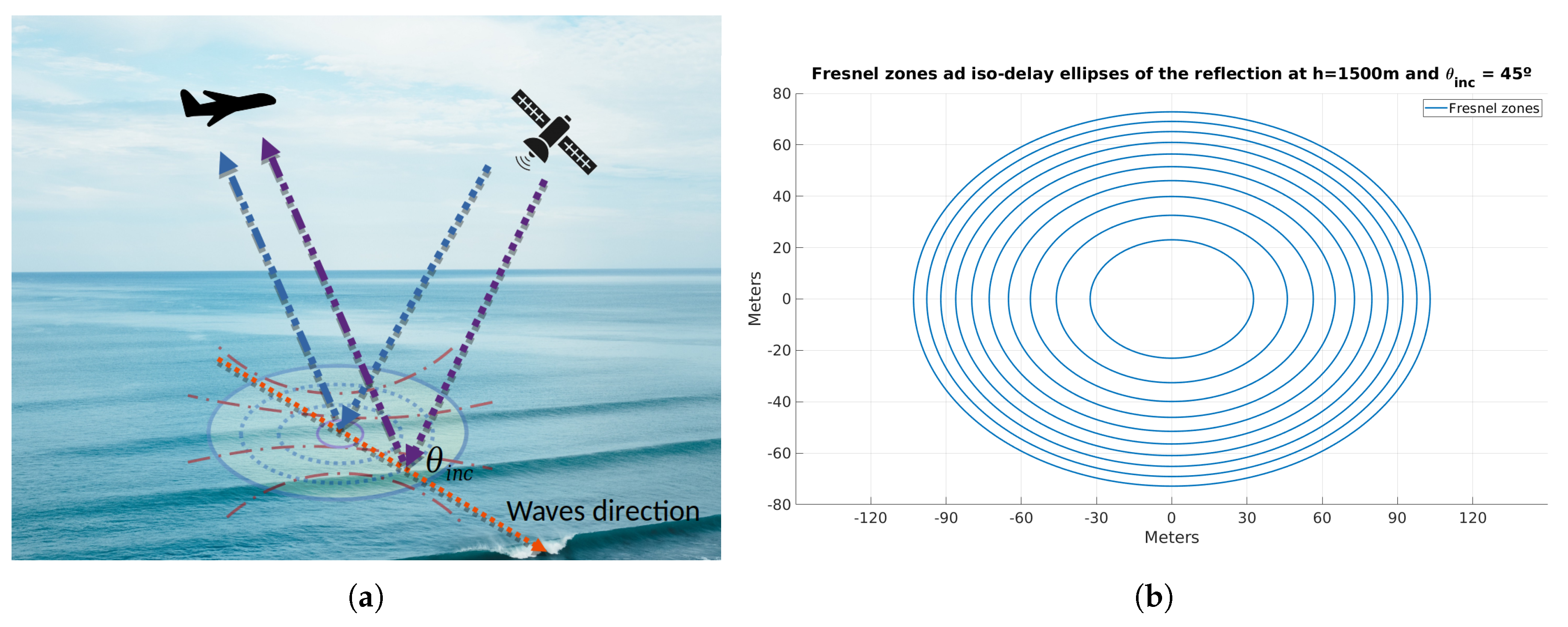
The reflection scenario is illustrated in
Figure 4. Note that, the semi-radius of the ellipse formed by the first Fresnel zone [
17] (i.e., the area that contains the specular reflection) in the described scenario is limited by the plane altitude as shown in Equation (
2).
where
cm for L5,
m, and
is the wave incidence angle. Therefore, at
,
m, whereas for an almost-nadir reflection as Beam 1 of Track 2,
m.
In this case, second and third reflections occurring in consecutive wave crests in the first Fresnel zone produce different signal wave fronts that are added constructively or destructively in the receiver antenna. However, thanks to the large bandwidth, and hence the very narrow auto-correlation [
18] function of the L5/E5a GNSS signal (i.e., 30 m in space), reflections from nearby crests with a distance between them larger than 30 m can produce second peaks in the retrieved waveform.
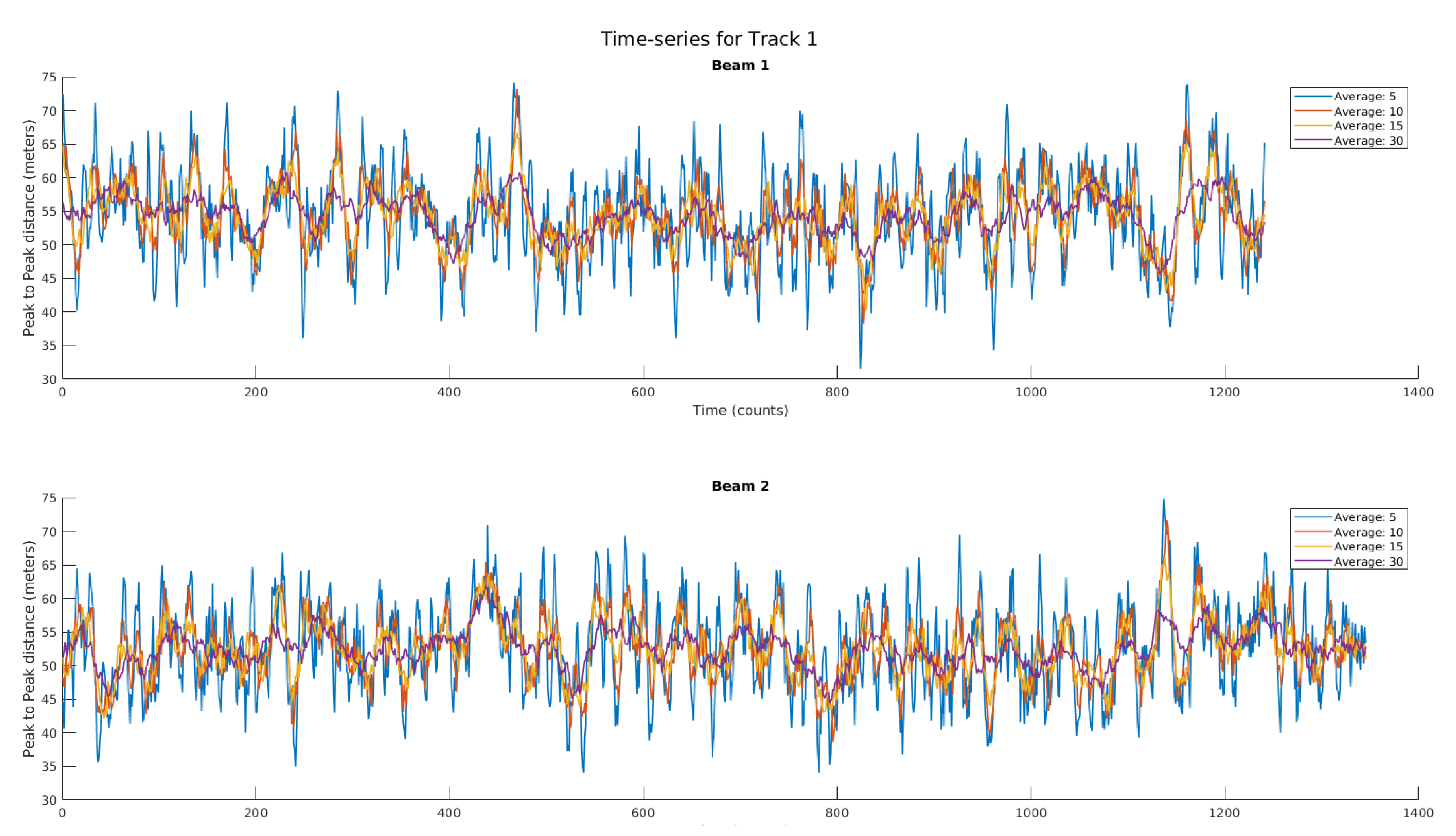
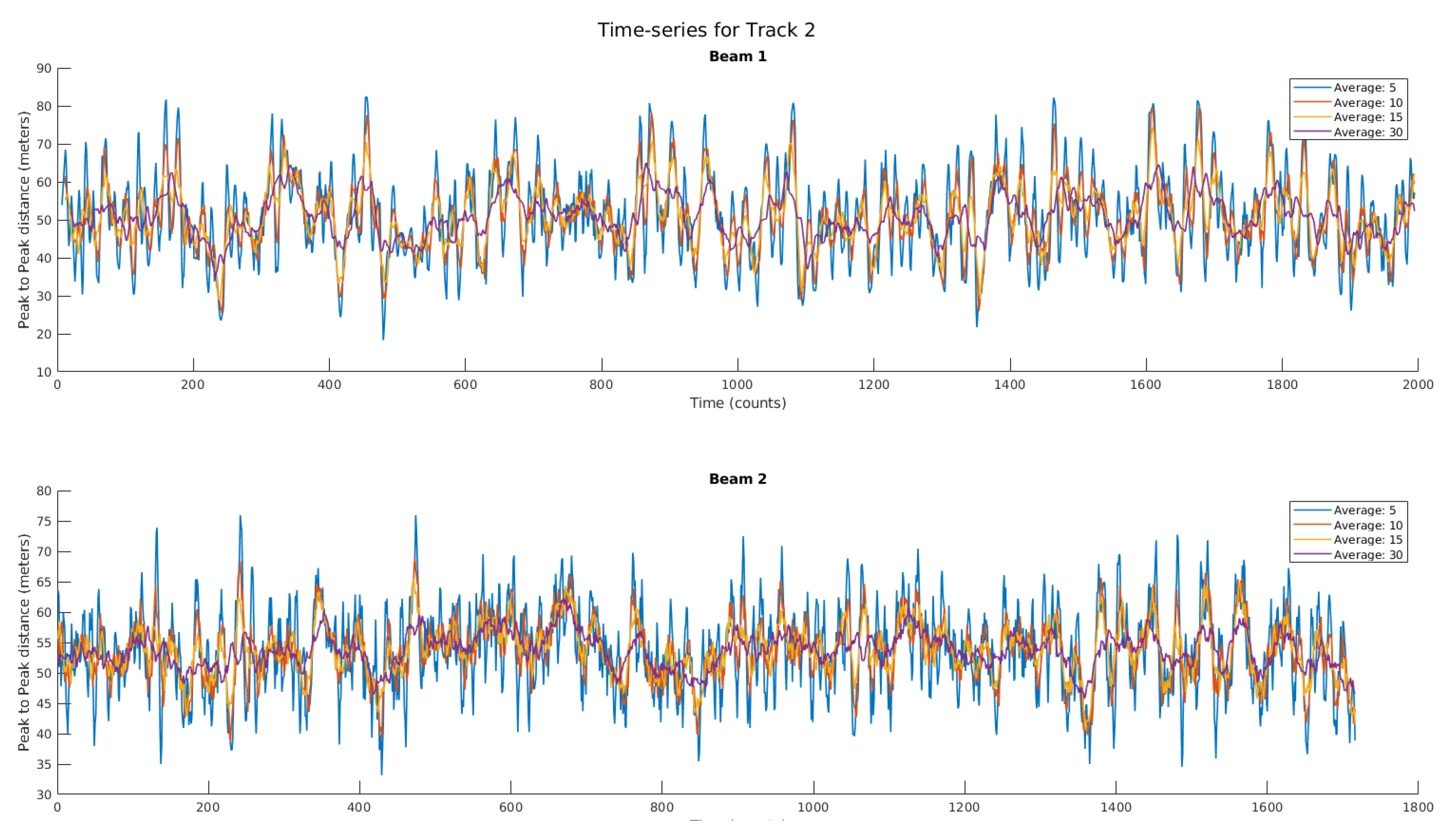
Due to the variability and the surface roughness of the ocean, the distance between two crests varies. In this case, where wind wave and swell wave components are both strong and also with different directions of propagation, the peak-to-peak distance is not preserved from one realization to the next one.
Finally, the peak-to-peak distance does not only reproduce the crest-to-crest between two consecutive waves, but also a modulation depending on the height between the two waves where the reflection has occurred.
3.1. Waveform Simulation
As opposed to reflections in L1 C/A, where the spatial resolution is mostly limited by the chip length (i.e., 300 m), the new GPS L5 or Galileo E5a signals have 10 times higher spatial resolution, as the auto-correlation function is 10 times narrower (i.e., 30 m in space), allowing de reception of multiple specular points with a distance larger than 30 m. In this case, any reflection from any point separated by more than 30 m produces a secondary peak on the retrieved waveform instead of a blurring on the retrieved wavelength.
This section shows different simulation scenarios of the retrieved waveforms modulated by a forward scattering occurring at the crests of the waves, belonging to different Fresnel zones (
Figure 4). To do so, a given PRN of a GPS signal at L5 (
) is sampled at 32.768 MHz (to have better granularity and mimic the MIR sampling ratio) which is then delayed and added as in Equation (
3). Note that, due to the sampling used, the distance from the peak to the zero of the auto-correlation (i.e., half the width of the whole auto-correlation function) is ∼3.2 samples.
where
is the resulting PRN sequence at the
kth sample, sampled at 32.768 MHz,
is the amplitude coefficient applied to each sample of the clean PRN sequence,
S, and
N is the length of the
vector, which represents the reflection scenario, where for this example is set to 10, causing a delay up to three L5 chips.
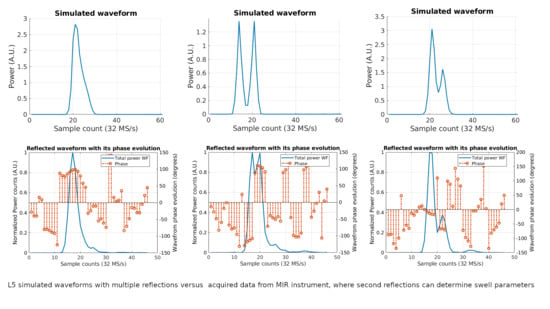
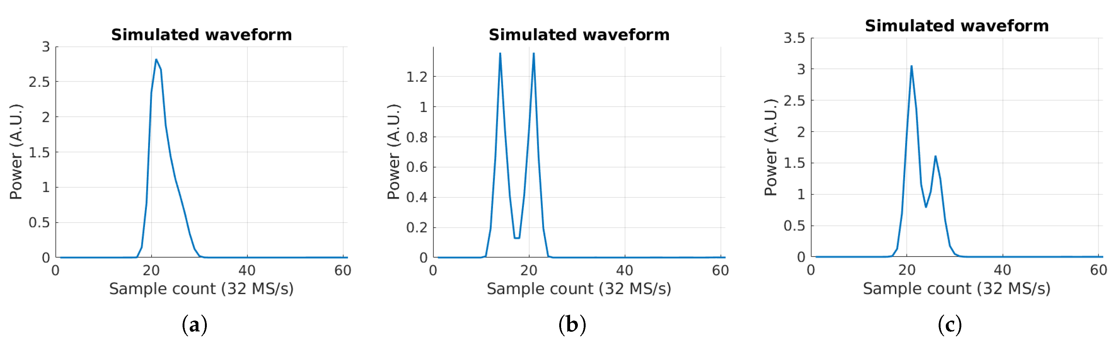
In order to illustrate this concept, three simulated waveforms are computed with different
c coefficients. In the first example, using
a reflection scenario is computed with lots of small contributions from all the Fresnel zones near the specular point. This produces a waveform as in
Figure 6a, where the power decreases, and no secondary peaks are found. However, using
produces two identical peaks which are easily distinguished. Note that, the separation between the peaks in samples is seven samples. In order to convert the sample distance into a tangible magnitude, the same method as in Equation (
10) from [
9] is used here in Equation (
4).
where
c is the speed of light,
[m/s], and
is the receiver sampling rate,
[S/s].
Applying it to
Figure 6b, the distance between the two specular reflections (identified as
and
in previous example), a distance of 64 meters is retrieved.
However, reflections are not always as perfect as in
Figure 6b. A third simulation (
Figure 6c) is generated using a more realistic case, with
, trying to reproduce two crests separated by five samples or 45 meters. Note that, the amplitudes of the neighbor areas have been also included, but they do not affect the high amplitude specular reflection contribution.
3.2. Evolution of Complex Waveforms in a Single Beam
The previous section has shown three different simulated waveforms synthetically generated to illustrate the concept of a second specular reflection in a consecutive wave crest around the second to sixth Fresnel zones.
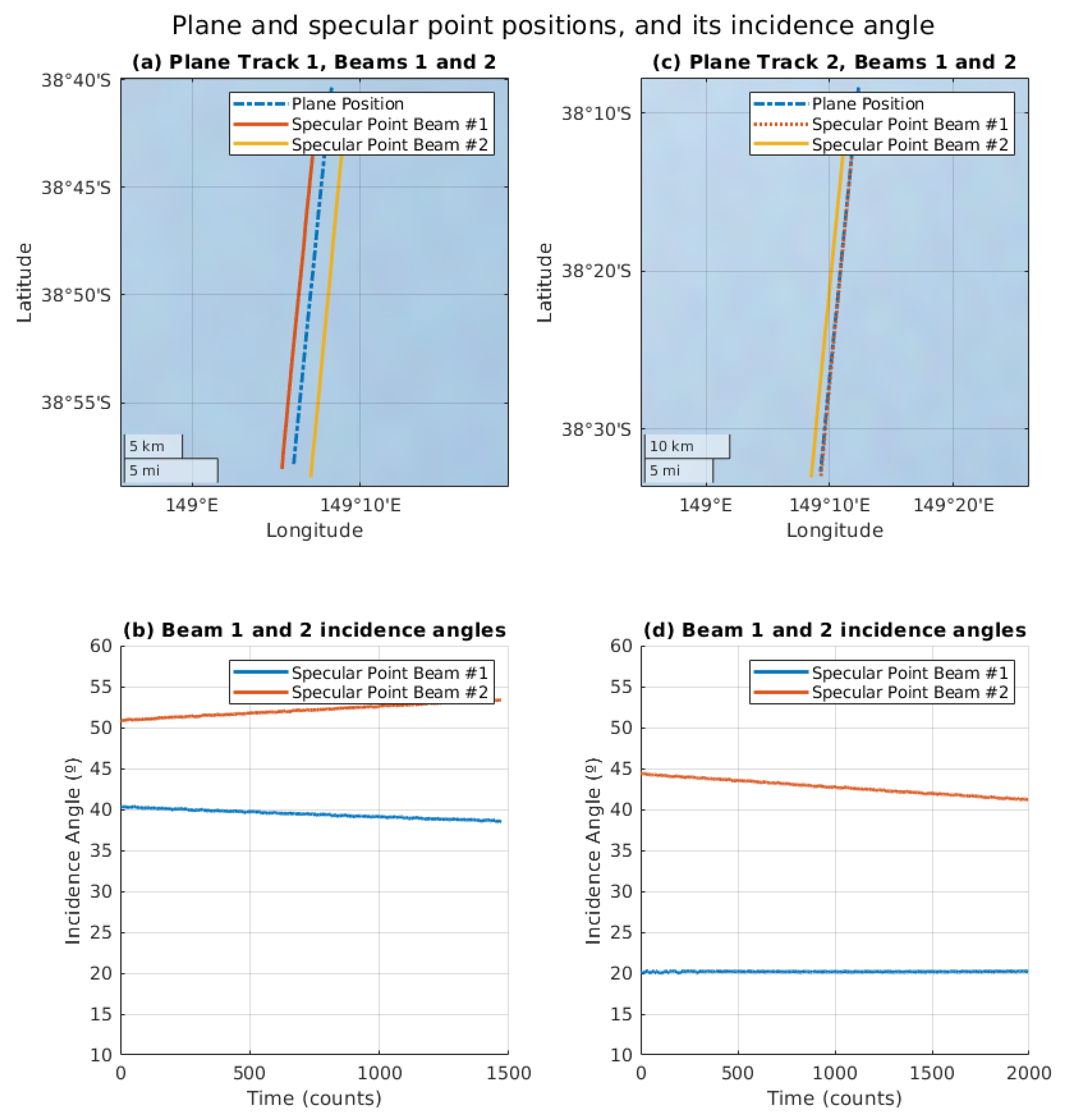
In this section, three consecutive measured waveforms (see
Figure 7) have been selected to illustrate these effects. The separation in time between each waveform is 600 ms, and they have been selected because of their similitude to the ones simulated in the previous section. Note that, the three selected waveforms are from Track 1 Beam 1, and both amplitude and phase evolution of the waveform are shown.
The first waveform (
Figure 7a) shows an example similar to the one in
Figure 6a, where very small contributions from all nearby Fresnel zones causes a blurring of the tail of the waveform.
The main peak is around sample count 17, with a phase approximately constant around +100°. Furthermore, there is a second small peak (in sample 25) around eight samples (i.e., 73 m in space) after the main one (in sample 17). The distance between the peaks indicates that small reflections are coming from the sixth to eighth Fresnel zones.
The second waveform (
Figure 7b) shows a example similar to the one in
Figure 6b, but with the reflection occurring in a closer Fresnel zone. In this case, the distance between these two peaks is three samples or ∼30 m, which corresponds to a reflection in the second Fresnel zone. Compared to the first waveform, the reflections occurred within the first Fresnel zone causing a blurring and a widening of the L5 auto-correlation function are now split in two different peaks.
As seen, the first peak (in sample 17) has a phase of ∼−110°, and the second peak (in sample 20) has a phase of ∼110° (i.e., close to the phase of the peak in
Figure 7b), with a relative phase difference ∼220°, corresponding to reflection in the second Fresnel zone, as both are separated more than 180°. Note that, there is a strong phase jump between the two peaks, indicating that both reflections are coherent (i.e., the phase information is preserved in both cases). As in the previous case, this third peak (in sample count 26) has an approximately constant phase around −50°. In addition and similar to the first waveform, a third small peak is also present nine samples (i.e., 82 m in space) away from the very first one. In this case, the reflection is taking place between the eighth and the tenth Fresnel zones.
Finally, the third waveform (
Figure 7c) shows a similar shape as the simulation in
Figure 6c, with a relative high second peak (in sample 22) in the reflected waveform which in this case is five samples from the main one (in sample 17). In this last case, the phase evolution is approximately constant in both peaks with a strong jump in the transition between them (i.e., very small incoherent reflection from other Fresnel zones). Note that in this case the relative phase difference is ∼50°, but as the delay in time is ∼45 m, the reflection takes place further away than the second Fresnel zone, the phase with respect to the first peak has advanced at least 180°. Therefore, the absolute phase shift between the two peaks is ∼315°.
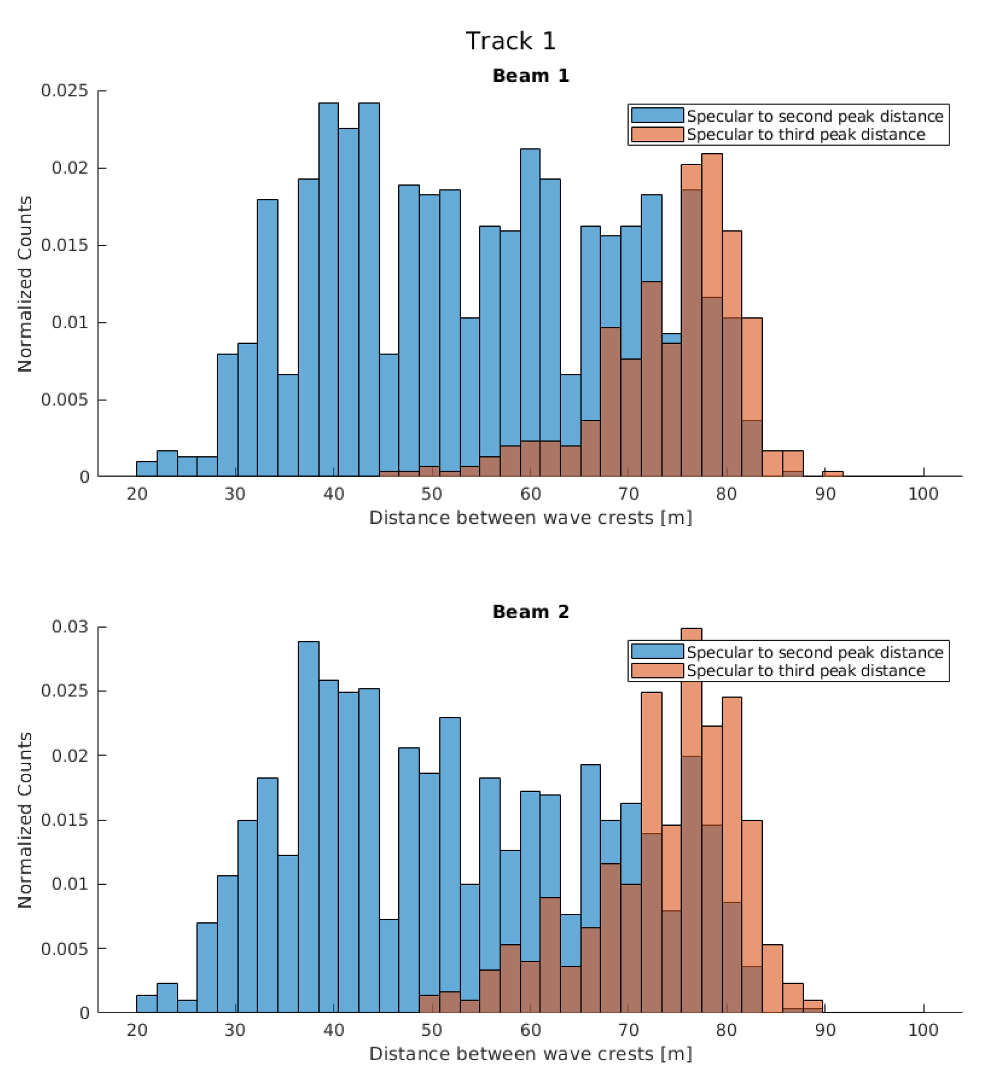
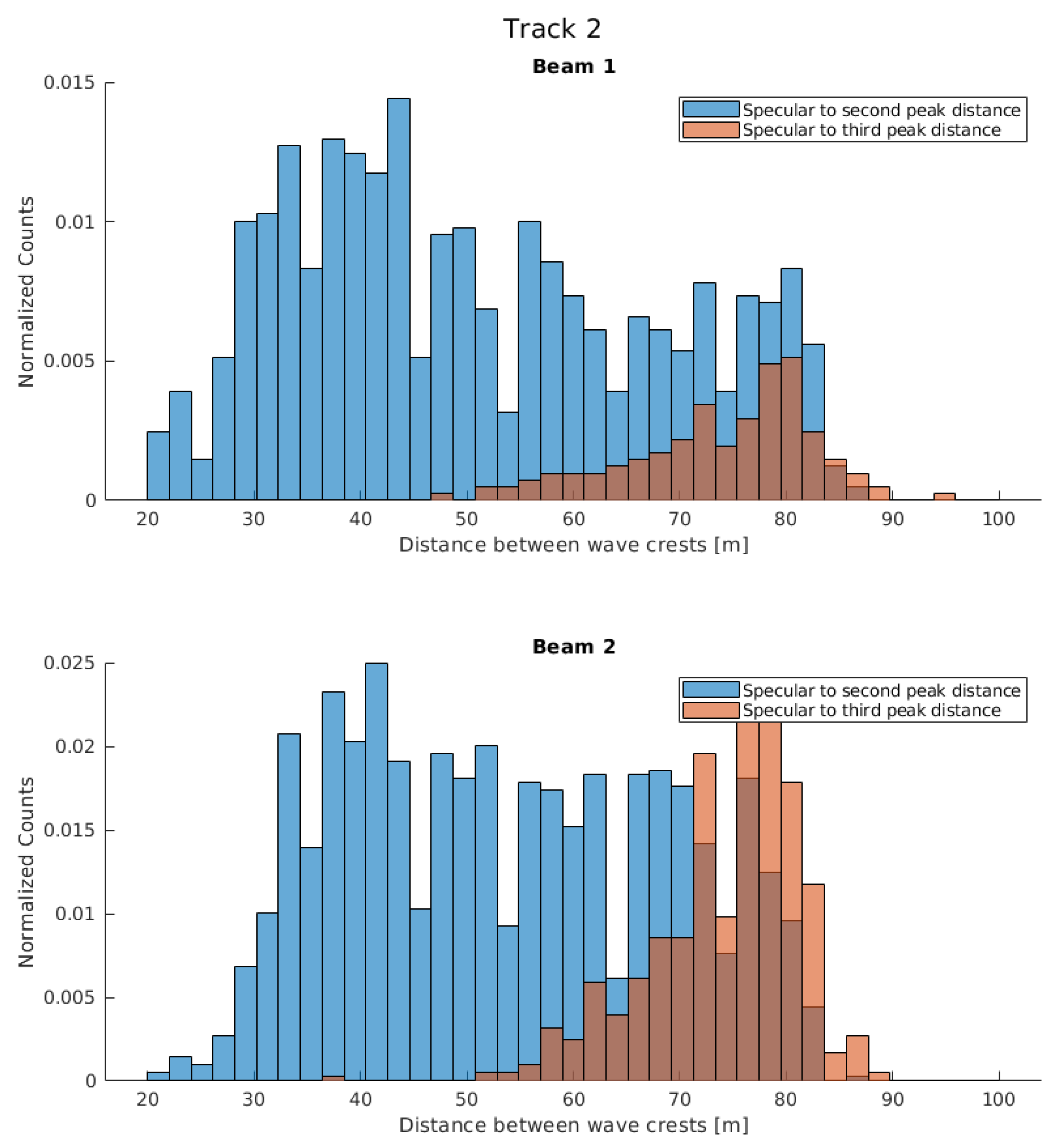
3.3. First Waveform Analysis: Determination of the Crest-to-Crest Distance from Peak-to-Peak Distance
The last section showed three examples of three different waveforms retrieved from Track 1 Beam 1, where the location of the second peak varies with time. Furthermore, it has been shown that this second reflection comes from a different Fresnel zone, and in some cases present a coherent component (i.e., a single specular reflection over a wave crest).
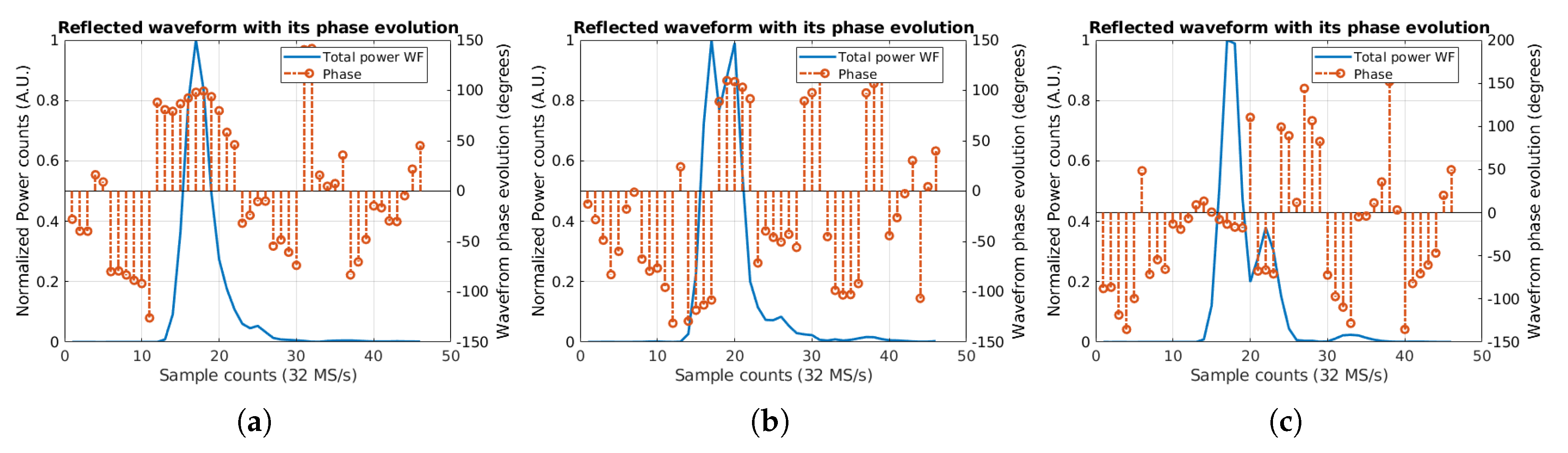
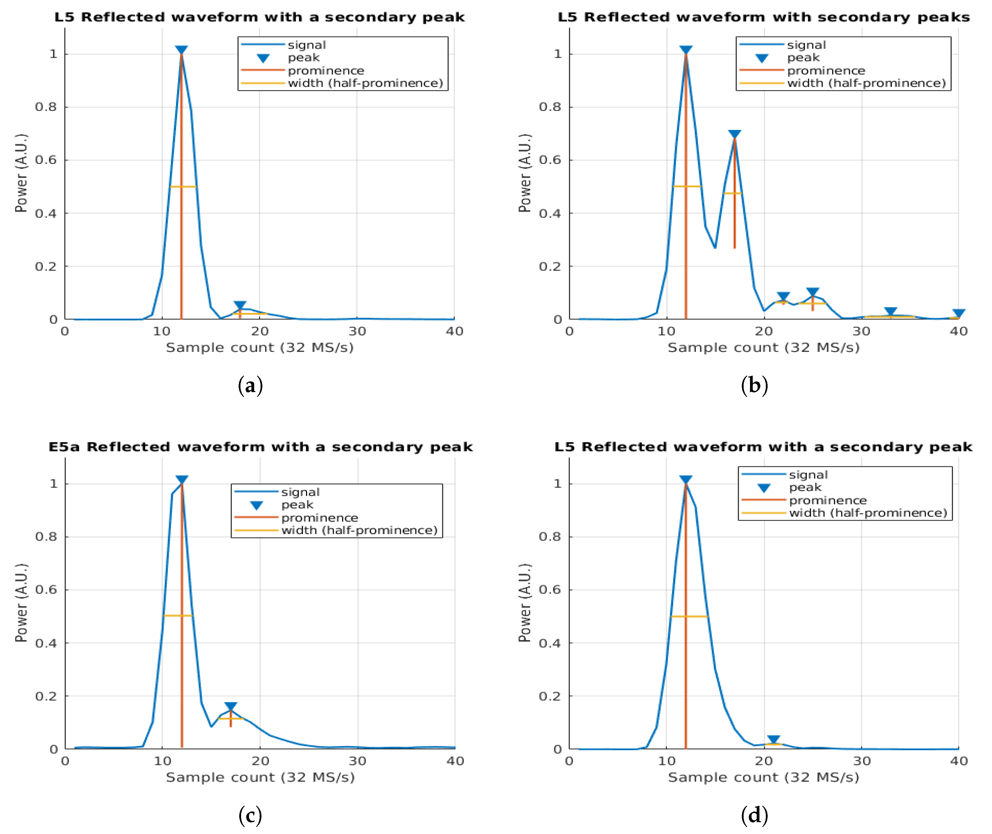
Figure 8 illustrates the example of different consecutive peaks present in the GNSS waveforms originated by the forward scattering on two consecutive wave crests, but now in the two beams for the two tracks of the flight.
Note that, the two waveforms for each track (i.e., beams 1 and 2 for Track 1 and beams 1 and 2 for Track 2) are taken at the same moment. As seen, the four waveforms present, at least, one second reflection.
Analyzing each of the tracks,
Figure 8a,c present a single second reflection at six samples from the specular one. For the beam 2 case,
Figure 8b presents a very large second reflection at six samples from the specular one. In addition, two small reflections are taking place 10 and 13 samples from the specular one. Finally,
Figure 8d shows a very low secondary reflection point at nine samples from the main peak.
Applying Equation (
4) to the waveform shown in
Figure 8, the distance between the peaks in meters are: 54.9 m for both
Figure 8a,c, 54.9 m for the first peak of
Figure 8b, and 91.5 m for the third peak. Finally for
Figure 8d, the distance between the peaks is 82.4 m.
Comparing those retrieved waveforms to the simulated waveforms from
Figure 6, it is possible to identify a clear similitude between them, where the second peak (i.e., the one in
Figure 8b) reminds the simulated in
Figure 6c, due to a specular reflection over a wave crest.
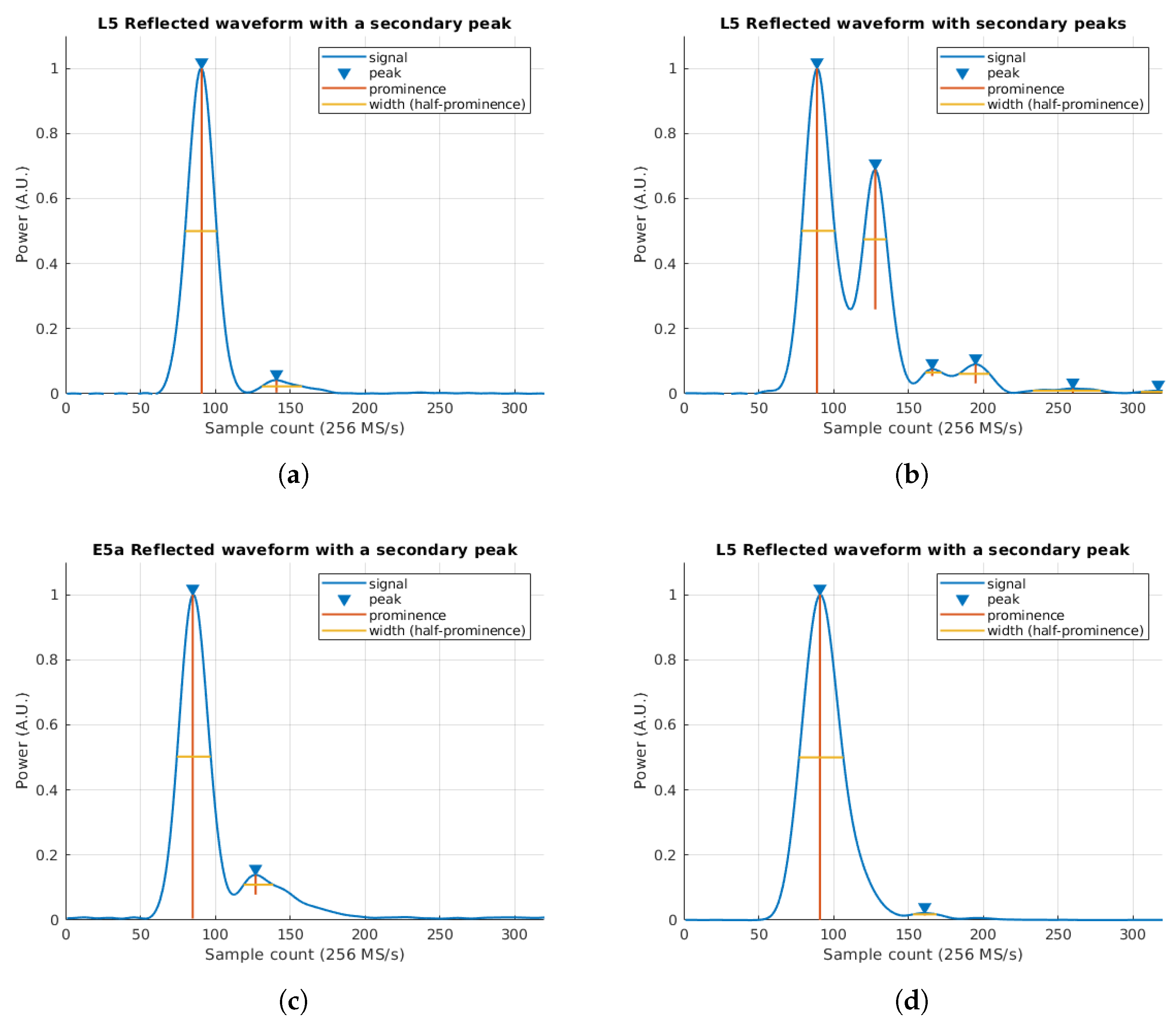
In order to improve the estimations of the separation between peaks in the waveform, since raw data was acquired satisfying the Nyquist criteria at baseband for L5/E5a signals (i.e., MHz), therefore the signal can be re-sampled without loss of information. Therefore, waveforms are re-sampled using the Fourier interpolation method (i.e., by inverse FFT of the zero-padded FFT of the waveform), and the local maxima of the interpolated waveform is located. The first two maxima of the waveform are the ones used to retrieve the distance between two consecutive wave crests. The difference in samples between the two peaks position is then converted into meters following the same approach as in previous section, but with a sampling rate scaled by the interpolation rate K.
The selection of this parameter is a trade-off between computational requirements and accuracy when selecting the final position of the multiple peaks. In order to efficiently apply the Fourier interpolation using the Fast Fourier Transform, the signal shall be a multiple of 2, and hence the interpolation rate K, shall be a multiple of 2 as well. In addition, the larger the K parameter is, the lower is the error determination of the peak position of the reflected waveform. For this case an interpolation rate of has a peak position uncertainty of 4.5 meters, and a has a peak position uncertainty of ∼1 m.
In this case, an interpolation rate of
has been selected (i.e., now
MHz). Furthermore,
Figure 9 shows the re-sampled version of the waveforms in
Figure 8 following the Fourier interpolation method.
The re-sampled versions of the waveforms show a better spatial resolution when estimating the peak-to-peak distance. In this case the distance in samples is: 50, 39, 42, and 70 respectively form (a) to (d). Moreover, the third peak of
Figure 9b is located at 77 samples from the specular one.
Applying Equation (
4) to the above sample distances, the retrieved crest-to-crest distance (
) in meters is: 57.2, 44.6, 48, and 80.1 m respectively for (a) to (d), and 88.1 m for the third peak of (b).
Table 2 compares the values prior to the re-sampling with the re-sampled values. Note that, the estimation of both the first peak position is enhanced thanks to the FFT interpolation. In addition, the estimation of the position of the second peaks is also enhanced. A proper estimation of the position of both peaks is crucial to better determine the distance between the two reflections (i.e., the two wave crests). Note the difference in Beam 2 of Track 1 and Beam 1 of Track 2, where the first approach does not show the proper crest-to-crest distance, introducing an error of almost 10 m in the measurement.
This section has covered the simulation and its comparison with real data of different scenarios where different specular reflections are generating second and even third peaks on the reflected waveform. The study on the phase evolution in this secondary peaks shows that the second reflection is coherent, and hence is coming from a different specular point, as was detailed in
Figure 5. Finally, the use of FFT interpolation enhances the determination of the peak-to-peak distance, showing a better granularity when determining this magnitude.

 ,
, 


