Article

Rimaal: A Sand Buried Structure of Possible Impact Origin in the Sahara: Optical and Radar Remote Sensing Investigation

Department of Earth and Ocean Sciences, University of North Carolina Wilmington, 601 South College Road, Wilmington, NC 28403-5944, USA
Remote Sens. 2018, 10(6), 880; https://doi.org/10.3390/rs10060880
Submission received: 24 April 2018 / Revised: 13 May 2018 / Accepted: 4 June 2018 / Published: 5 June 2018
(This article belongs to the Section Remote Sensing in Geology, Geomorphology and Hydrology)

Abstract

:
This work communicates the discovery of a sandy buried 10.5 km diameter near-circular structure in the eastern part of the Great Sahara in North Africa. Rimaal, meaning “sand” in Arabic, is given as the name for this structure since it is largely concealed beneath the Sahara Aeolian sand. Remote sensing image fusion and transformation of multispectral data (from Landsat-8) and synthetic aperture radar (from Sentinel-1 and ALOS PALSAR), of dual wavelengths (C and L-bands) and multi-polarization (HV, VV, HH, and HV), were adopted in this work. The optical and microwave hybrid imagery enabled the combining of surface spectral properties and subsurface roughness information for better understanding of the Rimaal structure. The long wavelength of the radar, in particular, enabled the penetration of desert sands and the revealing of the proposed structure. The structure exhibits a clear outer rim with traces of concentric faults, an annular flat basin and an inner ring surrounding remnants of a highly eroded central peak. Radar imagery clearly shows the interior wall of the structure is incised with radial pattern gullies that originate at or near the crater periphery, implying a much steeper rim wall in the past. In addition, data reveals a circumferential of a paleoriver course that flows along a curved path parallel to the crater’s western margin indicating the plausible presence of a concentric ring graben related to the inferred structure. The defined crater boundary is coincident with a shallow semi-circular-like basin in the SRTM elevation data. The structure portrays considerable modifications by extensive long-term Aeolian and fluvial erosion. Residing in the Cretaceous Nubian Sandstone formation suggests an old age of ≤65 Ma for the structure. If proven to be of an impact origin, the Rimaal structure could help in understanding the early evolution of the landscape of the Eastern Sahara and holds promise for hosting economically valuable ore deposits and hydrocarbon resources in the region.

1. Introduction

Bombardment by meteorites was a major geological process during the early history of Earth [1]. Unlike the Earth, the lack of the geological and atmospheric process on the Moon and other planets have prevented erosion of their impact craters. However, scars of these geologic forces and the past cratered Earth’s surfaces have been deeply erased by erosion and plate tectonic processes [2]. The discovery of new impact structures is not only of high importance to gain an understanding of the Earth’s early history, but also has economic significance as possible hosts of valuable ore deposits (e.g., gold and uranium) and hydrocarbon resources (e.g., oil and natural gas) [3,4]. For example, in North America alone, approximately nine out of 19 confirmed impact craters were exploited for oil and gas with a daily production of 2–30 million barrels of oil and more than 42 million m3 of gas of gas [5]. Consequently, it is worthwhile to search for new unknown terrestrial impact structures.
Terrestrial craters are composed largely of two basic types: small, simple craters (<4 km in diameter) and large, complex craters (>4 km in diameter) [6]. A simple crater is a small bowl-shaped depression, with a structurally uplifted rim, which includes an overturned flap and ejecta. A complex crater, on the other hand, exhibits a structurally complex outer rim with a terraced wall, a topographically lower annular trough, and a central topographic peak [7]. Today, there are about 190 confirmed terrestrial impact craters (simple and complex) listed in the Earth Impact Database (http://www.unb.ca/passc/ImpactDatabase). The distribution of these impact structures, as mapped by [4], illustrates a significant crater clustering in North America, Eurasia, and Australia, whereas the remaining continents, particularly Africa, lack their share of impact craters recorded at the same level.
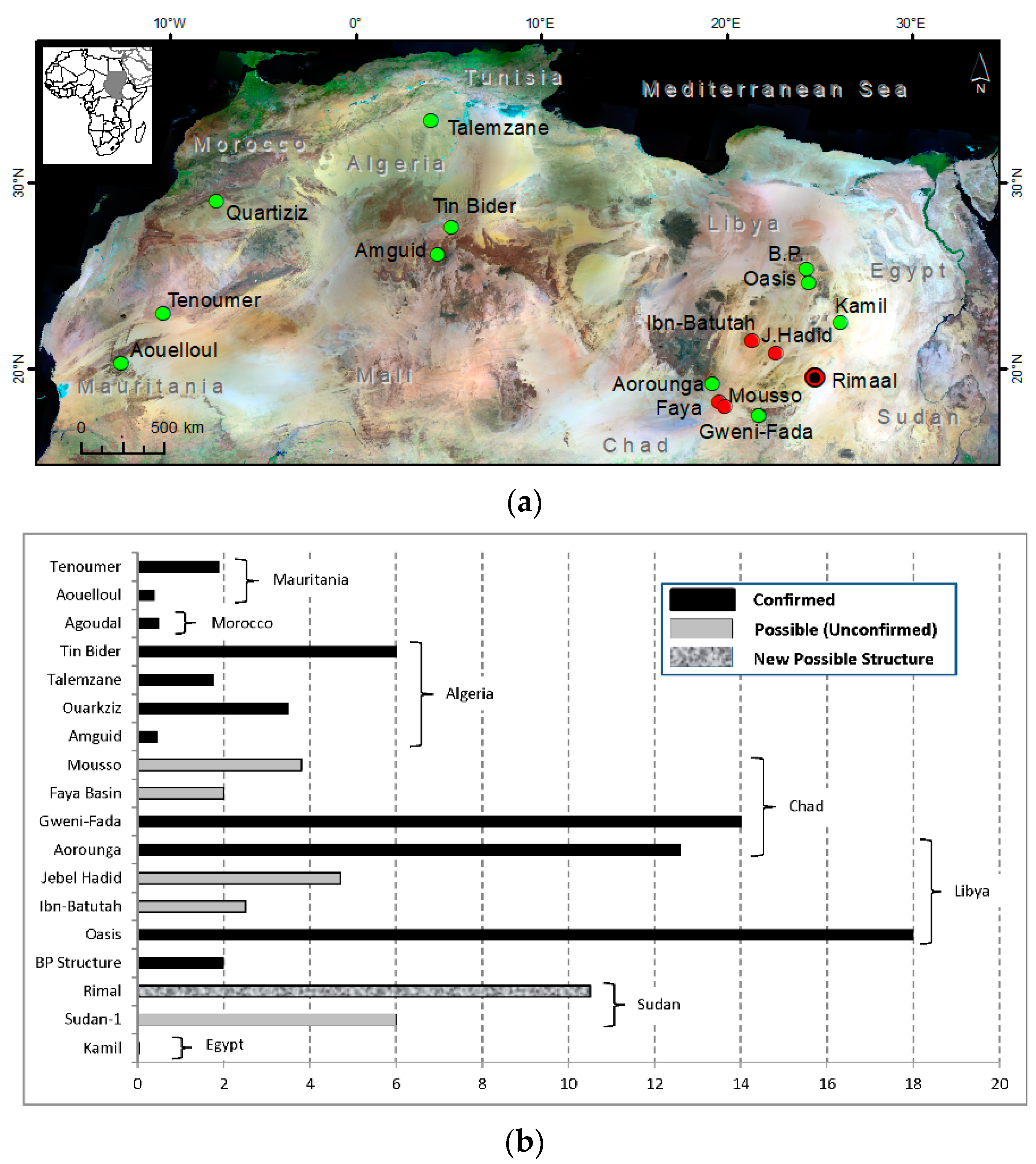
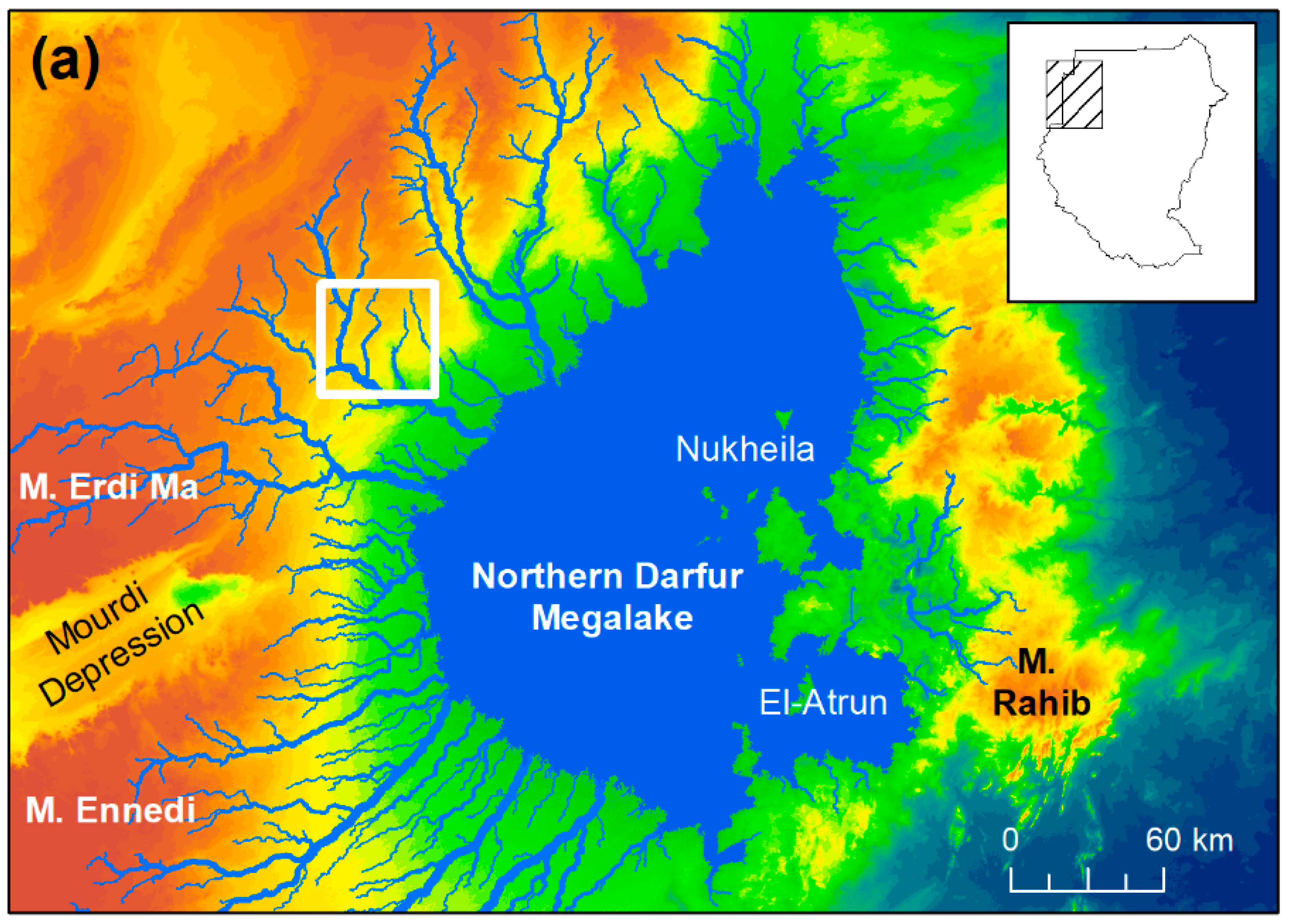
To date, only 20 structures were confirmed to be of an impact origin in the entire African continent. In addition, 49 structures are currently cited as being of potential impact origin and still awaiting field verification. Approximately, 55% of the confirmed structures in Africa are found in the Great Sahara alone [4] (Figure 1). In fact, the Sahara has long been known to host a large number of these structures which were found either during oil field explorations (e.g., the B.P. confirmed structure by [8]) or during the mapping of ancient river courses and lake basins for groundwater exploration (e.g., the Ibn-Batutah structure by [9]). There are seven structures that still remain to be discovered, buried beneath the dry sand of the desert. Presently, the harsh conditions and difficult accessibility are impeding the exploration of the vast area of the Great Sahara by ground-based techniques, making satellite data the only feasible means to hunt for suspected impact structures (e.g., [9,10]).
Over the last four decades, the growing number and quality of space imagers has strongly contributed to the identification of possible impact structures (e.g., [9,11]) which usually appear as distinct ring anomalies marking the original Earth surface. Unlike optical sensors, which can only image the surface of the desert, long-wave microwave sensors can unveil sand-hidden subsurface features [12]. In particular, radar images at C and L bands have successfully revealed sand-buried paleoriver courses and lake basins in several parts of the Great Sahara [13,14,15,16,17]. An important property of imaging radar is its ability to penetrate dry desert sand and produce images of the shallow subsurface terrain [15]. For radar wave penetration, the sand cover needs to be fine-grained, physically homogeneous, and extremely dry with a moisture content of less than 1%. The low dielectric constant of the Sahara sand results in a low attenuation and maximum penetration for the radar waves [18]. These criteria are all satisfied in the sandy desert of North Africa.
Remote sensing has contributed to the discovery of several suspected impact structures in the Sahara region. Out of the 13 confirmed structures cited in North Africa, about five impact craters were found in the eastern sector of the Great Sahara clustered in Southeastern Libya, Southwestern Egypt, and Northern Chad. Yet, no circular structure has been cited in the neighboring Sahara area in Northwestern Sudan. With vast areas of desert, Sudan still holds high potential for the discovery of impact craters. This work, therefore, is aiming at exploring a new large crater-like structure of possible impact origin in the Northwestern Sudan desert using optical and radar satellite data. A thorough examination of the morphology and the regional influence exerted by the conceivable impact event is considered in this work.
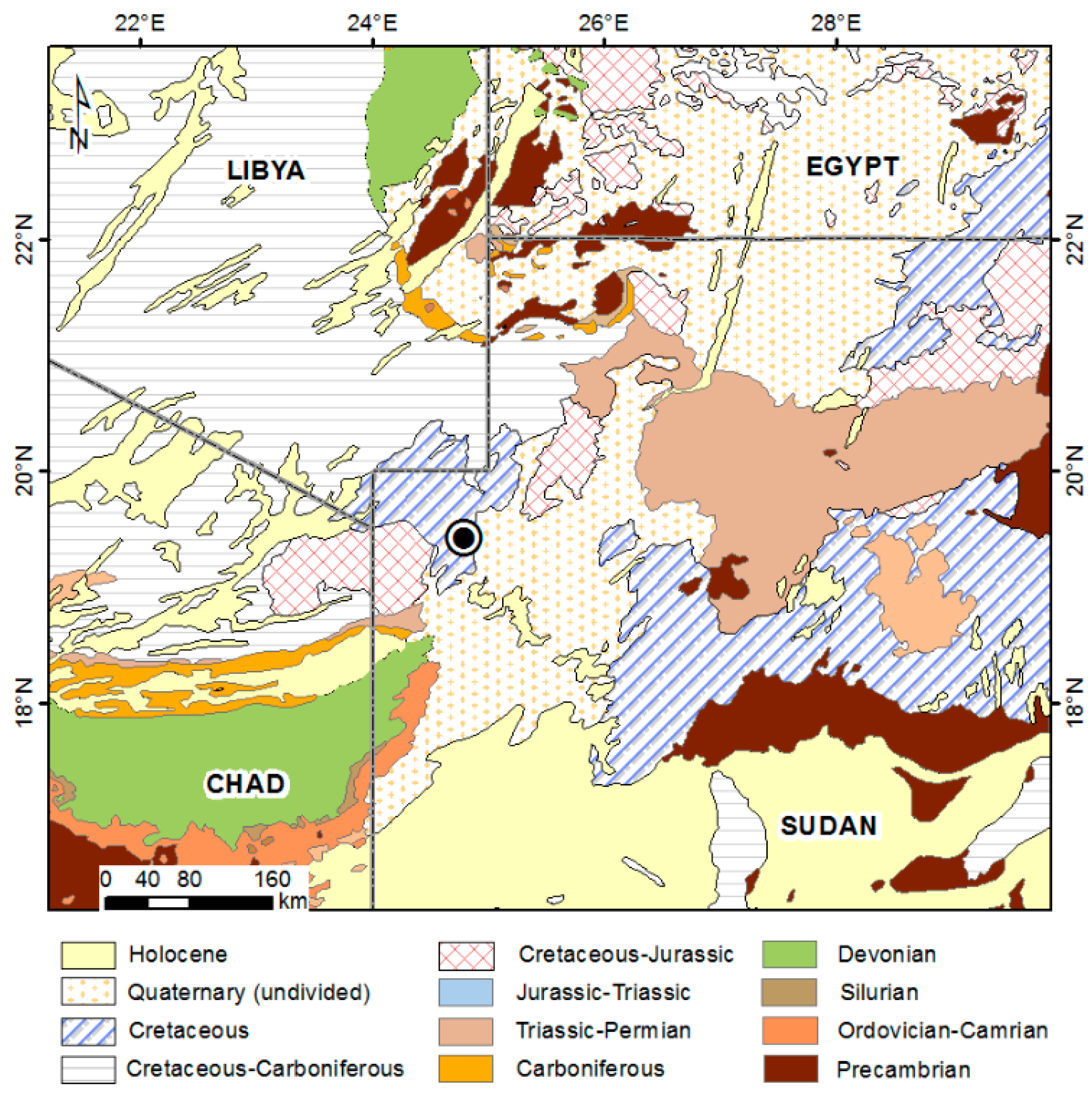
The discovered Rimaal circular structure is centered at 21°34′10″ N and 20°50′15″ E, about 280 km south of Uweinat Mountain. It is located in the prefecture of the State of Northern Darfur in Sudan about 654 km north of Al-Fashir City. As there are no prominent landmarks or geographic features in the immediate vicinity of the structure, Rimaal, meaning “sand” in Arabic, is given as the name for this structure since it is largely concealed beneath Aeolian sand cover. The subsurface geology of the region is not very well known; nevertheless, the region, in general, is mapped as Mesozoic Nubian Sandstone [19] (Figure 2). The thickness of the Nubian Sandston in the eastern Sahara region is unknown, but it can generally reach a maximum thickness of 1700 m in some parts [20].

2. Materials and Methods

Remote sensing is an important tool for the initial recognition of suspected impact structures, particularly in regions that are made up of the same rock as the surroundings. Optical imagery (Multispectral Sentinel-2 and Landsat-8 (LS8), microwave data (Sentinel-1 and ALOS PALSAR), and digital elevation data (Shuttle Radar Topography Mission—SRTM) were used in this study.

2.1. Optical Data

It is vital to use multispectral data and compare it with microwave data in desert regions in order to determine if the portrayed features are on the surface or in the near-surface. Both Sentinel-2 and Landsat-8 (LS-8) data were employed in this study. Sentinel-2, acquired in 25 April 2018, provides thirteen spectral bands with a spatial resolution that ranged from 10 m to 60 m for the visible, NIR (near infrared), and SWIR (shortwave infrared) wavelengths. All spectral bands, except channels 9 and 10 (the water vapor and cirrus detection bands, respectively), were used in this research. LS8, acquired in 22 October 2017, provides eleven spectral channels with a spatial resolution of 30 m for the visible, NIR and SWIR wavelengths, 100 m for the TIR (thermal infrared), and 15 m for the panchromatic band. All spectral channels, except bands 8 and 9 (the panchromatic and cirrus detection bands, respectively), were used in the present study. The Sentinel-2 and LS-8 raw images show little contrast due to the relative homogeneity of the surface cover type in the study area. The high inter-spectral-band correlation, which commonly encountered in multispectral data, results in a reduction of the interpretability of the satellite image.

2.2. Microwave Data

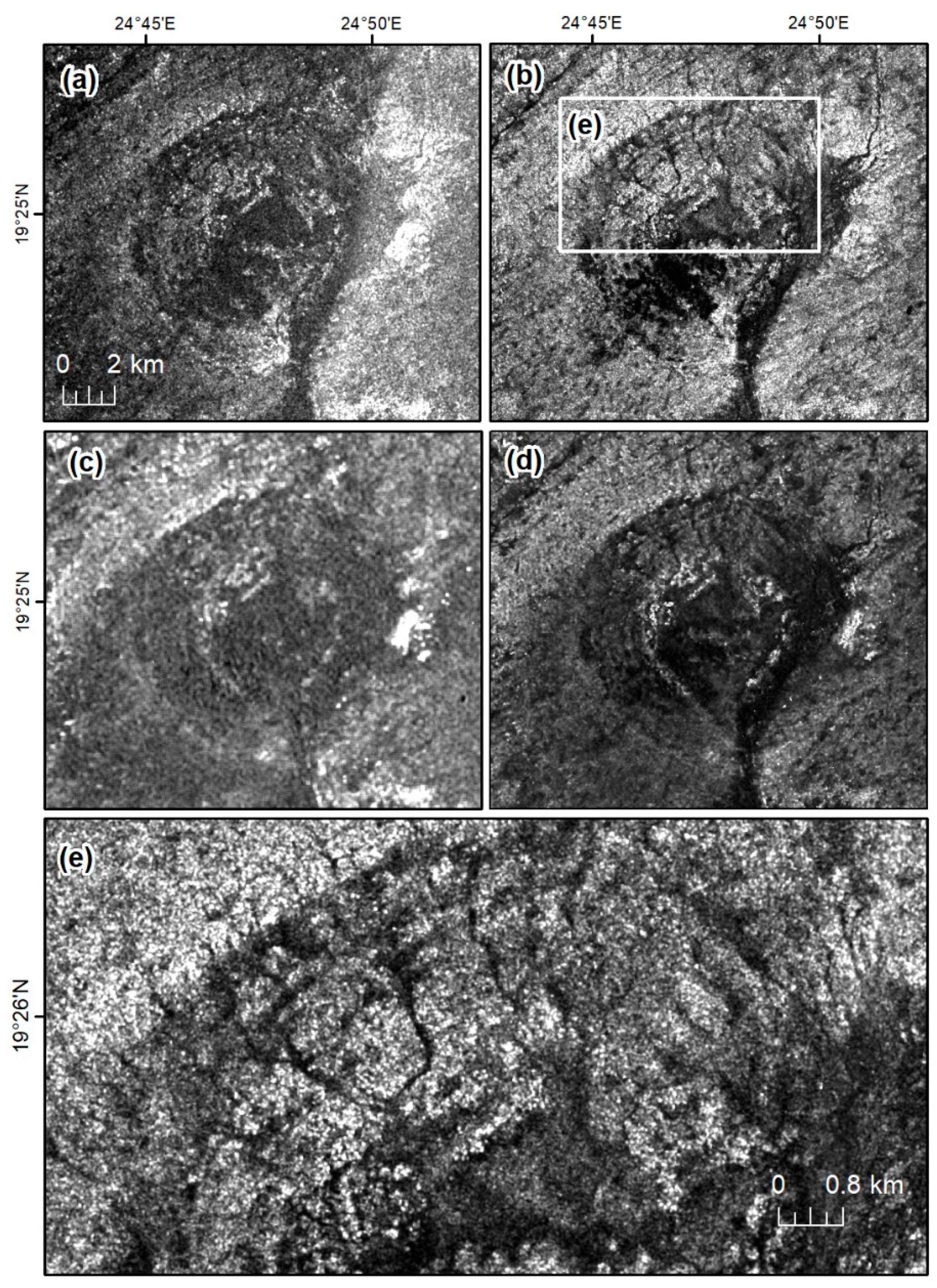
Radar data from both Sentinel-1 and ALOS Phased Array L-band Synthetic Aperture Radar (PALSAR) sensors were used. The Sentinel-1 system is a radar satellite constellation consisting of two C-band synthetic aperture radar sensors, Sentinel-1A (launched in April 2014) and Sentinel-1B (launched in April 2016), operating at 5.405 GHz, and dual-polarization support (HH+HV, VV+VH). Both satellites fly in the same near-polar, sun-synchronous orbit [22]. The Sentinel-1 image used in this study was acquired on 7 January 2015 in a descending orbit with an interferometric wide swath mode (IW), a large swath width of 250 km at ground resolutions of 5 m × 20 m, and dual polarizations of VV+VH.
An ascending ALOS PALSAR, Level 1.5 (geo-referenced amplitude image) data product, along with a radiometrically terrain-corrected (RTC) data product, was utilized in this study. The PALSAR scene with a multi-look complex (MLC) and geo-referenced to UTM coordinate data, was acquired in 13 July 2008 in a fine beam mode (FBD). It operates at 1.27 GHz (L-Band), and dual-polarization support of HH and HV at a spatial resolution of 12.5 m.
The process began by applying a precise orbit to the radar data and conducting image radiometric calibration to obtain backscattering values. The radar images were then speckle filtered using a Lee Sigma algorithm with a 5 × 5 pixel window. Terrain geocoding was then implemented using the SRTM 30 m DEM, along with the ALOS orbit data. Ortho images were projected to UTM coordinates, zone 35. A multi-looking function was then applied to generate accurate pixel dimensions (to produce square pixels out of rectangular SAR pixels). These processing sequences generated a geo-coded, orthorectified, terrain-corrected, radiometrically-calibrated and normalized Sentinel-1 and PALSAR scenes with a pixel size of 12.5 m.
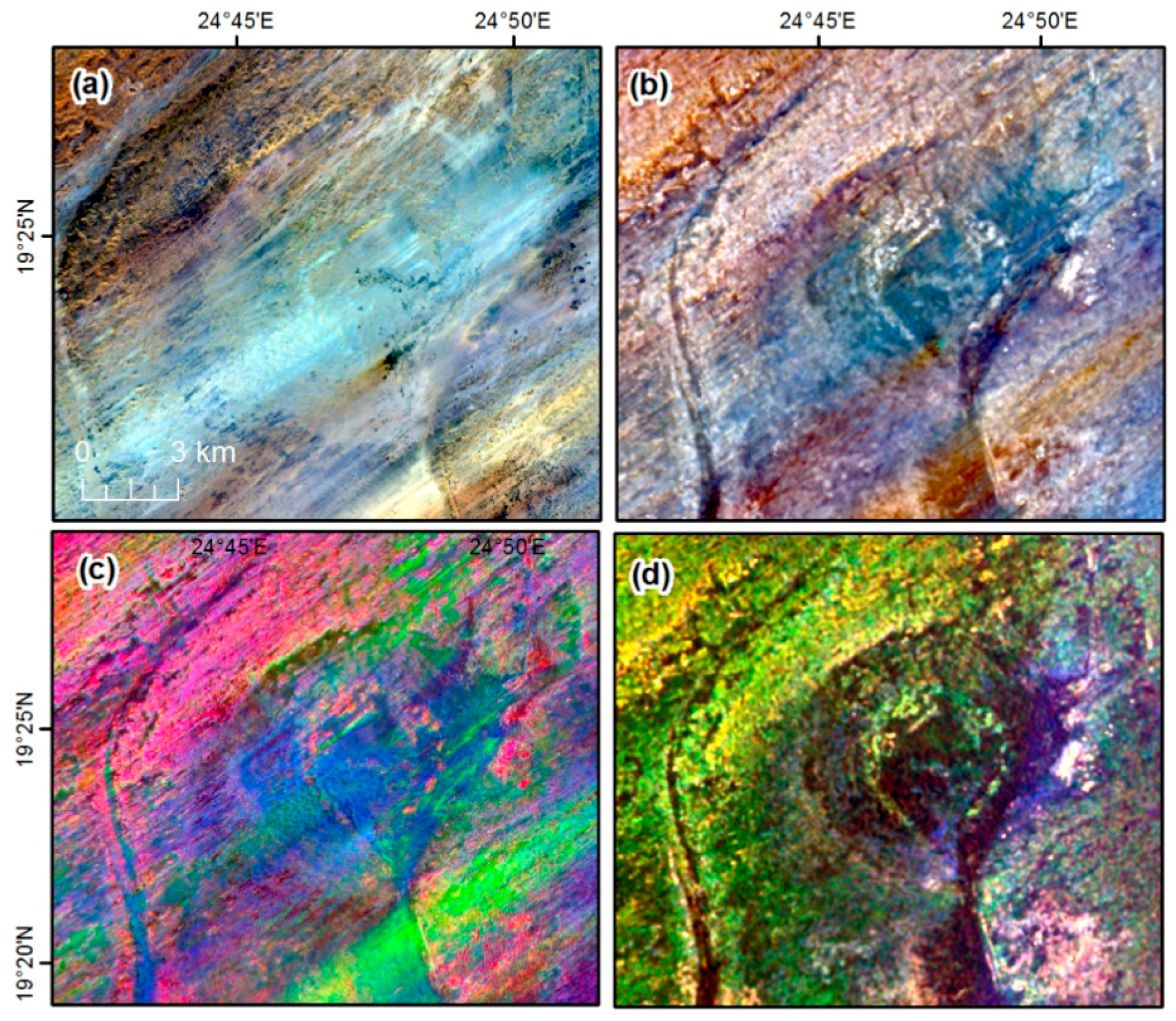
A LS8 and PALSAR image fusion, using the Gram Schmid algorithm [23], along with image transformation, using the minimum noise fraction (MNF) approach [24] were, therefore, applied to enhance the visual interpretability of the structure morphology. LS8 was fused together with the PALSAR L-HH imagery to produce a hybrid image that combines information of spectral properties (from the LS8) and surface roughness (from the PALSAR image) to improve the visual interpretation of the structural features and drainage systems in the surrounding area. The minimum noise fraction (MNF), a principal component transformation algorithm [24], was applied on a stacked multispectral LS8 and PALSAR microwave image to eliminate data redundancy and enhance the surficial mapping of the Rimaal structure. In the MNF procedure, the first phase results in transformed data in which the noise has unit variance and no band-to-band correlations, whereas the second phase is a standard PC transformation of the noise-whitened data, which gives rise to final outputs that are not correlated and are arranged in terms of decreasing information content [24]. The first three MNF components were used in the image analysis as they explain most of the variance in the scene (96.2%). The remaining components were discarded from the analysis since they contain proportion of noise contents. This procedure generated a hybrid MNF image that contains spectral and texture information and, thus, compensates for the limitation of using single remote sensing data products alone.

2.3. Digital Elevation Data

For digital topographic data, the 30 m SRTM and the 12.5 m ALOS PALSAR terrain dataset were used. Drainages were extracted based on a procedure by [25], with drainage pathways and flow accumulation delineated with the widely used 8D flow direction algorithm [17,26]. Drainage networks were generated using a threshold of 2000 cells and were then compared against the actual subsurface channels revealed in Sentinel-1 and PALSAR radar scenes. A good agreement was found between the derived drainage networks and those revealed by radar images, validating the hydrologic delineation process.
All the above data were projected to the Universal Transverse Mercator (UTM) and WGS84 datum. Satellite images and terrain model processing were carried out using ENVI 5.4 software and SARscape “image processing workbench” (Exelis Visual Information Solutions, Boulder, CO, USA) as well as ArcGIS 10.5.1 software (Environmental Systems Research Institute, Redlands, CA, USA). The above data were grouped in a geographic information system (GIS) to allow overlaying and correlation of the surface and near-surface features. Each data source added significant information which facilitated a clear examination of the Rimaal structure. In fact, the adopted procedure which utilizes optical and radar data was proven by the author to be effective in revealing crater structures is sandy desert regions, such as the Ibn-Batutah structure in Libya [9].

3. Results

3.1. Multispectral Data

Both Sentinel-2 and LS8 optical satellite images faintly show the Rimaal structure consists of a single circular wrinkle ridge surrounding a basin that is completely infilled by smooth sandy material (Figure 3). The area appears as a featureless desert surface, except for segments of ancient rivers that are most probably of Tertiary age [13]. The images barely reveal the structure as a light tonal circular feature coated by Aeolian sand. The topography of the area in Sentinel-2 and LS8 is relatively subdued with no obvious expression of a topographic rim to the Rimaal structure. In the visible part of the spectrum, the albedo of the filling sand is close to the albedo of the surrounding country rocks, leading to the subdued expression of the surface features [9]. In commonly used moderate to high spatial resolution multispectral data, such as LS, Sentinel-2, and ASTER (30 m and 10 m in the VNIR), sandy surfaces in areas that are made up of relatively low contrasting bedrocks show similar spectral responses that hinder detailed mapping or classification of the area. This issue could likely be improved when using very high spatial resolution multispectral data with spectral channels in the mid-infrared region of the spectrum (e.g., WorldView-3) [27].

3.2. Radar Data

The aptitude of radar signals to differentiate among distinct surface roughnesses is particularly advantageous in low contrasting sandy desert regions that show analogous spectral behaviors on multispectral data, as is the case of the present study area. Radar data clearly show an isolated crater-like structure of nearly spherical shape with a dark radar backscatter delimited by bright radar signals (Figure 3b). This can be interpreted as a smooth-sand floored basin (crater’s interior) delimited by a rough bedrock surface (crater’s outer rim). At the center of the structure, a near-circular ring feature of a bright radar backscatter, surrounded by a dark annular trough, is clearly visible.
In the Sentinel-1 image (Figure 4), the overall circularity of the Rimaal structure, however, was concealed, to some extent, along its eastern flank. This could be due to the presence of a coarse-grained material that covers a vast part of the structure and, thus, acts as a rough surface to the shorter radar wavelength of the Sentinel-1 C-band, causing a specular backscatter of bright radar signals. The Sentinel-1 C-band VV like-polarized image is, however, substantially superior in portraying the gullies that incised the interior wall of the structure’s outer rim. A close-up look at the structure divulges traces of concentric faults on the inner wall of the northern flank of the structure (Figure 4). Considering a penetration depth of 0.5 m for the Sentinel-1 C-band signals in a dry sand surface [18] leads to the proposition that the western and northern flanks of the Rimaal structure are covered by, at most, 50 cm of dry desert sand.
The longer wavelength of the PALSAR L-band (Figure 4) was capable of penetrating deeper (~3 m in dry fine sand) and reveal larger parts of the hidden eastern flank of the inferred crater when compared to that of Sentinel-1 C-band (with max penetration of 0.5 m in dry fine sand) [15,27]. Coarse grained material are smooth to the radar L-band and, thus, radar waves are capable of penetrating deeper and reflect less energy back to the radar’s receiving antenna. This allows key morphometric elements, like the structure’s annual trough, to appear dark in the radar L-band imagery. As a consequence, it provides greater contrast between the structure’s trough and its bright outer rim and central topographic ring and peak, emphasizing the overall circularity of the Rimaal structure. The co-polarized L-HH imagery shows a significant improvement in exposing the structure rim when compared to the cross-polarized imager (L-HV). In the L-HH imagery, the rim shows a stronger backscatter than the surroundings, therefore becoming easier to detect.

3.3. Fusion and Transformation of Multispectral and Radar Data

LS8 and PALSAR image fusion (Figure 5), using the Gram Schmid algorithm, along with multispectral and radar image transformation, using the MNF approach, have significantly boosted the visual interpretability of the structure’s morphology. Fusion and transformation of LS8 and radar data enabled the combining of information of spectral properties (from multispectral data) and surface roughness (from microwave data) to enhance the visibility of subtle surface and near-surface features of the Rimaal structure. The fused image reveals clearly the circularity of the structures and the radial drainage patterns buried beneath the Aeolian deposits. The fused image highlights extensive systems of NE–SW trending elongated sand dunes that run across the Rimaal structure and obscure much of the detail of the inner ring and the outer rim. The dunes’ orientation indicates a strong influence of the easterly trade wind in the area.
Figure 5 displays an RGB color composite image of a stacked Sentinel-1 C-VV and PALSAR L-HH and L-HV channels, which clearly reveals the morphology of a large part of the Rimaal structure. The structure is a 10.5 km-diameter near-circular bowl-shaped depression. Impact craters larger than 10 km in diameter are most probably created by a meteorite with diameter larger than 1 km [28]. Assuming a spherical projectile, the volume of the impactor of the Rimaal structure is estimated to be about 606 km3. It comprises a small, irregularly-shaped central peak surrounded by a near-circular 1 to 1.5 km wide ring feature of a strong radar backscatter. This is followed by a slightly flat radar dark annular trough, of a fairly uniform width of ~2.5 km surrounded by a radar bright outer rim. The inner wall of the rim exhibits traces of concentric faults. PALSAR surface roughness profile indicates a much coarser textured material of the crater interior than the surroundings. Here, the inner ring of the structure is made up of a significantly coarse textured material (e.g., bedrocks and boulders) than that of the annual trough of fine textured grains (e.g., fine Aeolian and fluvial deposits) (Figure 6). Typically, in complex impact craters, the central uplift structures are often more resistant to weathering than the surrounding crater fill of impact breccias and, thus, could be the only relic of deeply eroded impact craters [4].

3.4. Digital Elevation Data

In the terrain data, the Rimaal structure is gently undulating with low topographic relief. The radar defined crater periphery is coincident with a semicircular-like basin in the DEM (Figure 6).
A topographic profile derived from these data shows the structure as a bowl-like shallow depression that is nearly 45 m deep with a general tilt from west to east (Figure 7). The formation does not display a clear raised rim, particularly at its eastern side, and the wall is not as steep. The perpendicular alignment of the eastern side of the rim to the direction of the prevailing northeastern trade wind could be the reason for the rapid erosion of the eastern side in comparison to the western side of the structure. Although the terrain profile shows the interior of the structure to be flat with barely any sign of topographic expressions, PALSAR reveals a distinct surface roughness to the structure’s interior (Figure 7). In PALSAR, the inner ring and central peak appears to be made up of significantly coarser textured material than that of the structure annular basin which is characterized by fine-textured material.
The shallow depth of the Rimaal structure could be the result of filling by deposits, including impact breccia, as well as Aeolian and fluvial sediments. According to [7] for a complex impact structure, the true depth (the depth to the crater true floor from the top of the outer rim), and the apparent depth (the depth to the top of the breccia lens from the top of the outer rim), can follow the following empirical relationship:
d a = 0.13   D 1.06   a n d   d t = 0.28   d 1.02
where D is the final rim diameter in km, and d a and d t are the apparent and true depths in meters, respectively. Applying the formula in [7] to the Rimaal structure of a 10.5 km in diameter, yields an apparent depth of 243 m and an actual depth of 412 m. Based on the topographic data, the current depth of the structure is only 45 m, which means that about 80% of the crater’s depression is filled by debris and sediments. The deep erosion to the outer rim would have also contributed to the shallowness of the Rimaal structure. As apparent from the DEM topographic data, the structure betrays considerable modifications by extensive long-term fluvial erosion. The SRTM-delineated drainage network in the area illustrates the presence of river channels of southern flow directions (Figure 8), which drain toward the ancient mega-lake of Northern Darfur [29].

3.5. Hybrid Remote Sensing Data

Based on the hybrid remote sensing images (from passive, active, and elevation data), the morphology of the Rimaal structure is sketched (Figure 8). The spatial configurations of the paleorivers in the vicinity of the Rimaal structure show interesting patterns. The arrangements of these rivers can be used as indicators of the presence of the inferred crater at this locality. For example, the interior wall of the structure is incised with gullies that originate at or near the crater northern rim, implying a much steeper rim wall and erosion by precipitation-derived surface runoff in the past. The gullies clearly developed in a radial pattern and cut into radar-bright bedrock, providing evidence of the circularity of the structure. A few of these gullies flow southeast and joined together to form one water course. This course flows easterly to merge with a major paleoriver course (R1 in Figure 8). This eastern river, which is now dry, breaches the structure’s northeastern rim and runs through its eastern annular trough. Although it has a general south flow trend in the plateau, the R1 river course shows an abrupt change to the west when it reaches the inferred crater basin. The course of the R1 river has an obvious narrowness as it enters and exits the putative crater periphery, inferring a more resistant rim material, whereas the river course becomes wider within the Rimaal formation itself. Moreover, to the west of the Rimaal structure, a circumferential of a second paleoriver (R2 in Figure 8) is clearly visible in the microwave data. The shape of the river course indicates the plausible presence of a concentric ring graben related to the inferred structure. In the DEM, this waterway appears to flow along a curved path parallel to the western periphery of the structure, suggesting a causal relationship. In view of that, it appears that there is an intriguing spatial association of the paleorivers’ geomorphology with the inferred location of the structure. The geomorphological properties of the paleorivers provide additional evidence for the inferred crater and their presence suggests fluvial processes were among the key factors in the crater degradation.

4. Discussion

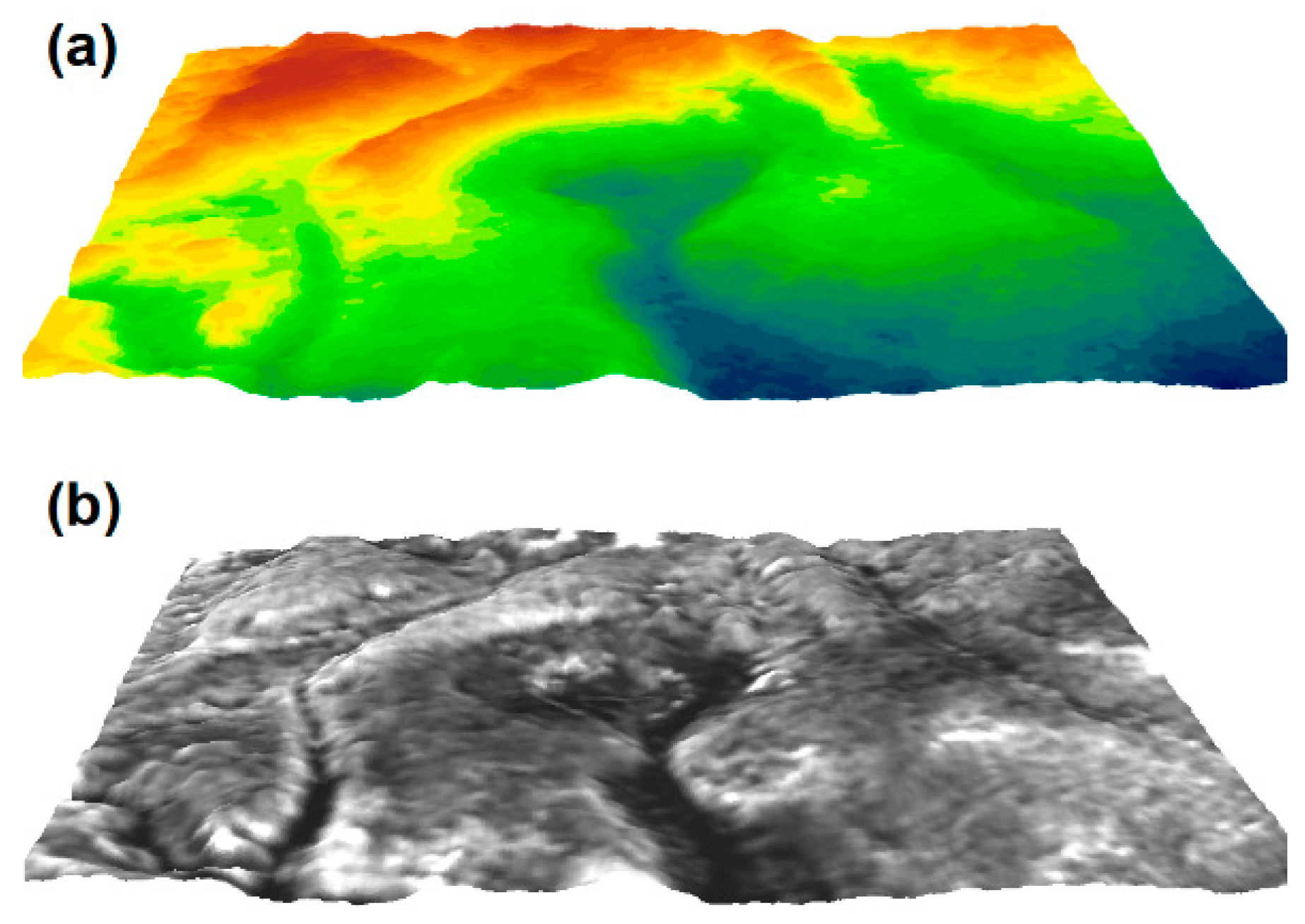
The four multispectral and radar and microwave satellite datasets of LS8, Sentinel-1, PALSAR, and SRTM were used to perform multisource data fusion and roughness analysis, in order to map the Rimaal circular structure. The results indicate that fusing satellite data collected from both the optical and microwave regions of the spectrum adds value over using a single data source. However, despite the benefits of combining optical and microwave data, image fusion techniques are not commonly used in studying and mapping possible impact craters. The actual Rimaal structure could also be a smaller relic of a formerly larger structure that has afterwards been eroded. Noticeable traces of a corroded central peak in the hybrid imagery might imply the old geological age of the Rimaal structure. Prominent central uplifts at impact structures are typically quite susceptible to erosion. At the present time, the interior of the Rimaal structure is mostly filled with quaternary sediments. The shallowness of the structure is believed to be attributed to the amount of sediment layers that have deposited within it by wind and surface runoff during wet pluvial. The fluvial activities of the incoming eastern paleoriver were most likely responsible for a large fraction of these sediments. If the impact origin hypothesis is confirmed, it is expected that the central peak of the structure is buried under layers of Aeolian and fluvial deposits.
It is plausible that in its early stage the Rimaal basin held a considerable amount of water that was supplied from the incoming eastern drainage. Accordingly, lacustrine conditions may have prevailed when water was copious in the past. The ponding water may have formed a local lake occupying at least its deepest part. This lake was probably broadly similar to the modern-day Bosumtwi Lake in Ghana. The latter lake is situated within an ancient complex impact crater that is about 10.5 km in diameter [30], equal to that of the Rimaal structure. The principal drainage cutting through the southern wall of the structure would have served as a spillway for the proposed lake. Lakes in rainy warm regions, such as the proposed Rimaal Lake, are known to accumulate organic-rich lacustrine sediments and, thus, are commonly viewed as analogues for other impact structures that contain economic reserves of oil and gas [31,32].
In fact, meteorite impact craters of comparable size and geologic setting to the Rimaal structure were found to host significant amounts of oil and gas reservoirs worldwide. In the US, for instance, the total annual commercial hydrocarbon production from nine exploited impact structures was estimated to be between USD$5 and USD$16 billion [5]. Among the impact structures that host rich oil and gas fields in the US are the Ames (16 km), Red Wing (9 km), Sierra Madera (~13 km), and the Marquez (~12.5 km). For example, the Red Wing Creek impact structure in North Dakota, one of the most productive oil basins in the US, has an estimated production of 12.7 million barrels of oil, whereas the Ames impact structure in Oklahoma produces about 7200 barrels of oil per day. For gas production, the Sierra Madera in Texas boasts about 122 million m3 daily. These structures are all formed in sedimentary rocks. In fact, the Sierra Madera and Marquez craters, in particular, resemble that of the Rimaal structure as they both have a comparable size and are formed in Cretaceous Sedimentary rocks with ages of less than 100 million years.
Typically, fracturing and brecciation resulting from meteorite impacts can cause significant porosity and permeability of the target rocks [3,33], therefore, most the likely produce a good quality oil reservoir. Here, the shock deformation and the generation of central uplift caused by the impact would make a substantially productive reservoir if filled with hydrocarbons [34]. Large impact events commonly fracture the ground surface to several kilometers deep and create pathways in a sedimentary basin for fluid migration from the hydrocarbon reservoirs at depth. The exact age of the proposed structure is yet to be estimated; however, a maximum age of the Rimaal structure is probably ≤65 Ma, as it most likely formed in sandstones of the Cretaceous age. In the Eastern Sahara, just west of the region where the Rimaal structure is found, lies the Al-Kufrah Basin, with a high potential hydrocarbon reservoir [35]. Since this reservoir is estimated as Late Triassic to Early Cretaceous in age [36], it can be assumed that the Rimaal structure postdates the hydrocarbon reservoir in this area. This suggests that the Rimaal structure might represent preferential conduits for fluid migration from such a potential reservoir.
The Rimaal structure is situated entirely in a vast area of monotonous Mesozoic sediment and is far from the large volcanic province of Awaynat massif and any known volcanic features in the region. Therefore, the volcanic origin for the structure formation is unlikely. Likewise, Maar formation and sand volcanism processes, produced by gas bubbles erupting through moist sands, can be discarded by the large size of the Rimaal structure (~86.6 km2). No salt plug or gypsum-karst features are known in the study area. The Rimaal structure is entirely carved in sandstone; accordingly, a dissolution karst origin for the structure can be ruled out. Lastly, a glacial origin cannot be inferred for Rimaal since the structure is located in the Great Sahara and circular glacial features, like kettles, could only be formed in loose sediments and not in the firm Nubian Sandstone where the structure exists.
Based on the above discussion, the endogenic processes for the formation of the Rimaal structure are improbable; therefore, an impact origin is proposed. To date, nine circular structures have been discovered in the Eastern Sahara, and all are excavated within the Nubian Sandstone Formation. Five of these structures have been confirmed as impact craters, which are Kamil in Egypt [37]; BP and Oasis in Libya [38,39]; and Aorounga and Gweni-Fada in Chad [40]. None was discovered yet in Sudan.
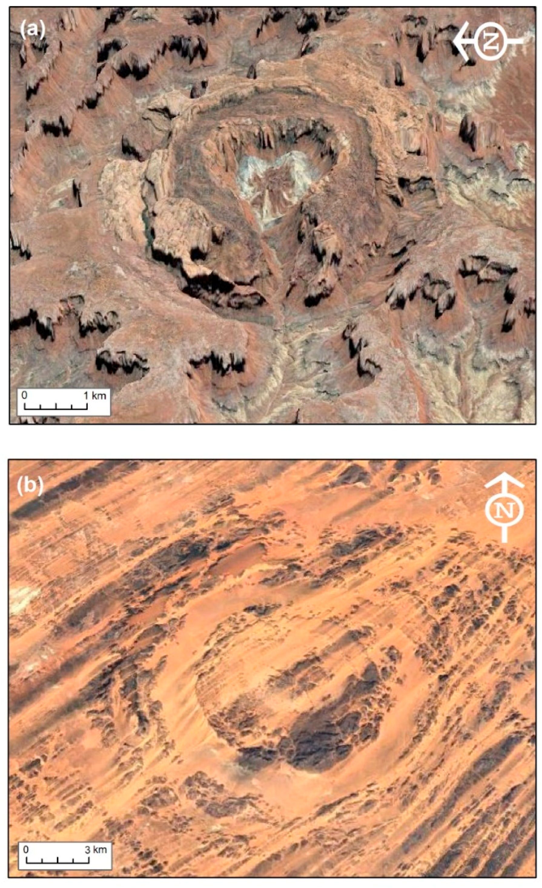
The morphology of the Rimaal structure bears a distinct morphological similarity to the Upheaval Dome impact complex crater in Utah, USA [41] (Figure 9). Both craters have central peaks that exhibit inner morphological depressions (appear as inner ring structures), and their outer rims are partially breached by river courses. The defined central inner ring of the Rimaal structure was also described for the Aorounga impact crater in the neighboring country of Chad [40] (Figure 9). In fact, other resemblances were found between the Rimaal and the Aorounga Crater, where both structures are situated in sandstone and are shielded by the Sahara sand and, thus, hardly visible by optical satellite images. The subsurface radar imaging capabilities facilitated the exposure of both structures.
With a diameter of 10.5 km, if the Rimaal structure is confirmed to be of an impact origin, it would be among the very few large complex impact craters found in Africa and the fourth largest structure in North Africa after Oasis, Gweni-Fada, and Aorounga impact craters. Rimaal might be a smaller relic of a formally larger structure that has been deeply eroded.

5. Conclusions

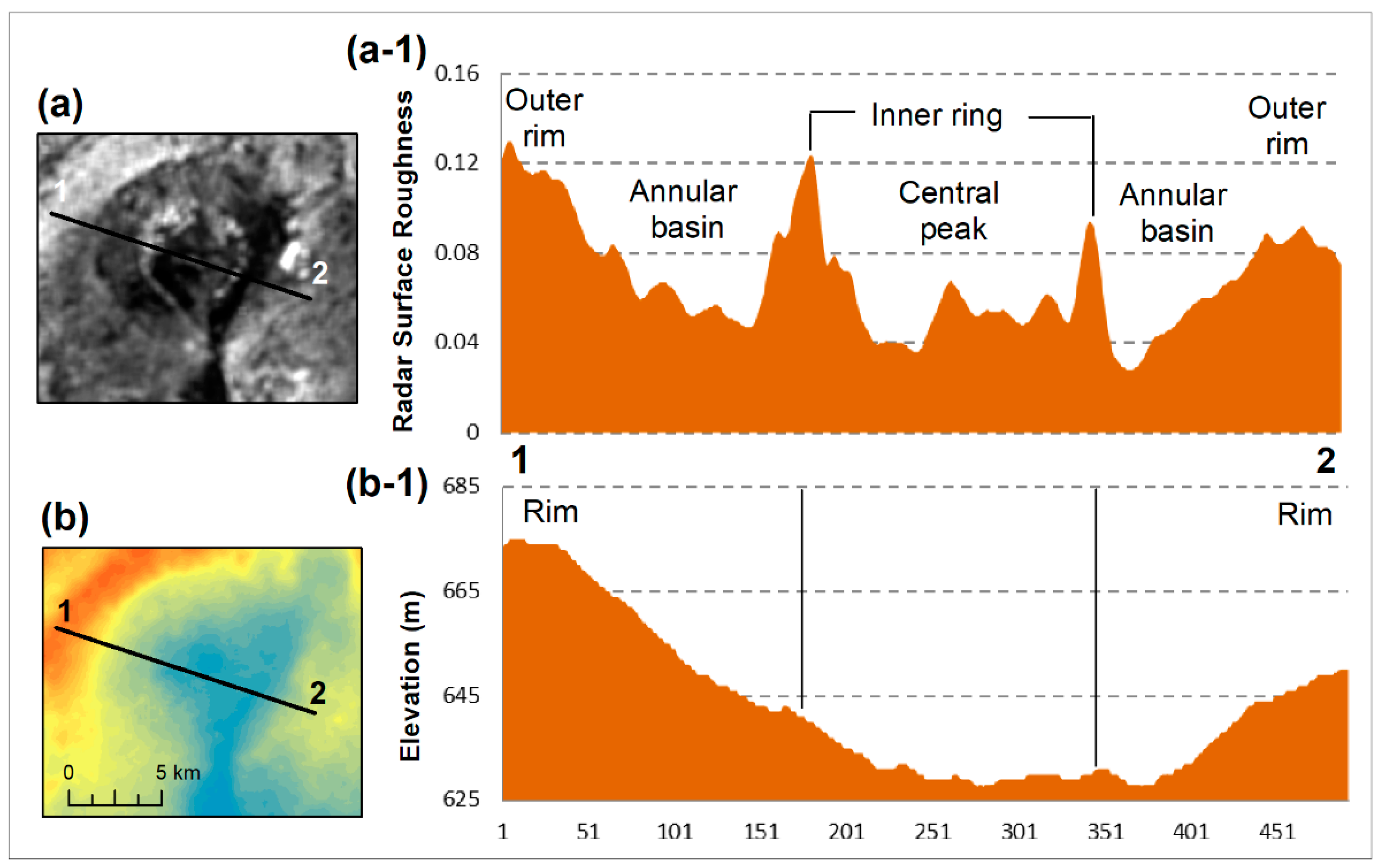
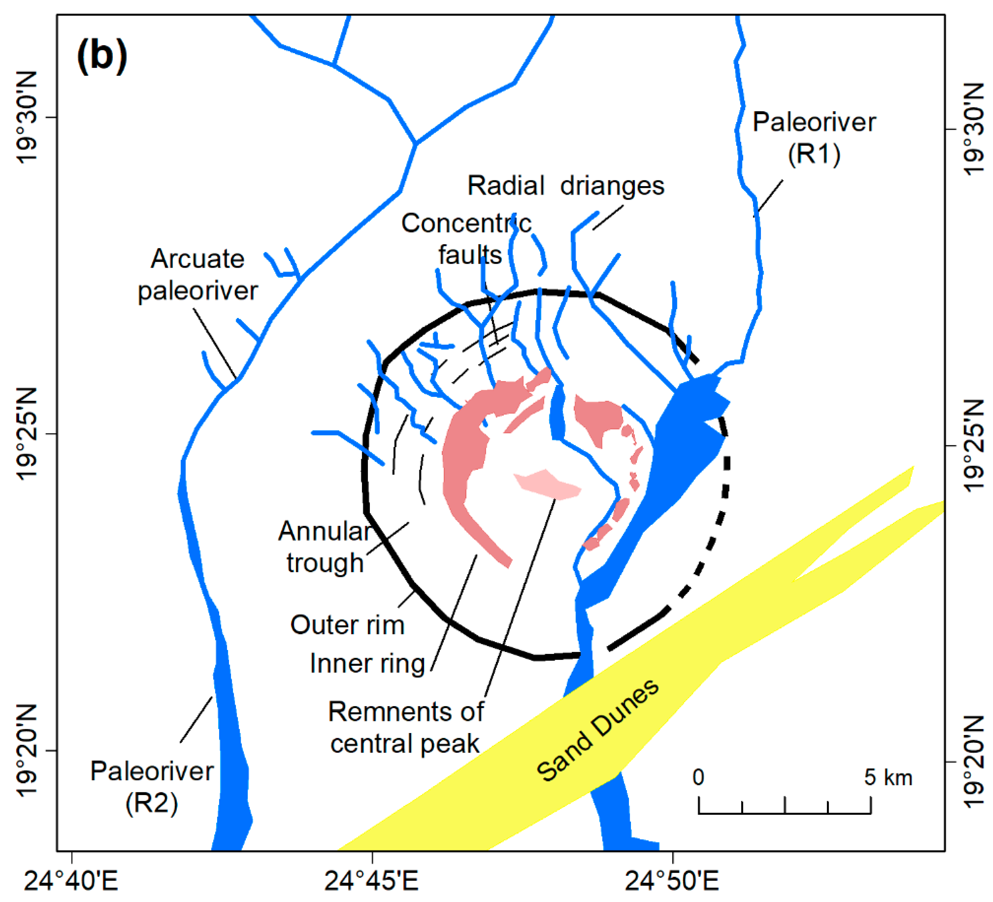
The presence of the vast ocean of sand sheets and dunes in the Great Sahara of Africa limits the ability to map, in detail, the region and understand its past landscape. The use of optical and microwave satellite data has led to the identification of a sandy buried complex crater-like structure in Northwestern Sudan. The long wavelength of radar data, in particular, enabled the penetration of desert sands and revealed the hidden Rimaal structure. The structure has a diameter of ~10.5 km with a low topographic expression. It exhibits a clear outer rim with traces of concentric faults, an annular basin, and an inner ring surrounding remnants of an extensively-eroded central peak. The structure is most likely of an old origin (≤65 Ma) considering the situation in Nubian Sandstone formation of Cretaceous age and the strongly eroded nature of its morphological elements. The discovery of this buried structure in the desert of Sudan demonstrates that the database of possible impact craters can be greatly improved in sandy desert regions worldwide by combining optical and radar satellite data through image fusion and transformation. This work shows that fusing multispectral data with microwave data of different frequencies (C and L-bands) and polarizations (HH, HV, and VV), can be of fundamental help for further in situ studies of the impact structures.
Field visits and rock samples are still required from in and around the structure for confirming or discarding Rimaal as an impact crater. Yet, visiting the region is currently quite challenging due to the environmental inaccessibility of the area and for security reasons. If proven to be of an impact origin, the Rimaal structure could be the first complex crater ever found in Sudan and one of the few structures with a developed inner ring known so far in Africa. More importantly, if confirmed, this structure could hold promise for hosting economically valuable ore deposits, such as gold and uranium, as well as hydrocarbon resources, including oil and natural gas, for the benefit of the nation of Sudan.

Author Contributions

The author conducted all the research work solely, including the detection of the previously-unknown buried circular structure, image processing, analyzing the data, obtaining the results, and writing the manuscript.

Acknowledgments

The author would like to express her appreciation for the anonymous reviewers and editors, whose comments have helped to improve the overall quality of this paper.

Conflicts of Interest

The authors declare no conflict of interest.

References

  1. Westbroek, H.H.; Stewart, R.R. The formation, morphology, and economic potential of meteorite impact craters. CREWES Res. Rep. 1996, 8, 1–26. [Google Scholar]
  2. Grieve, R.A.F.; Rupert, J.; Smith, J.; Therriault, A. The record of terrestrial impact cratering. GSA Today 1995, 5, 189–196. [Google Scholar] [CrossRef]
  3. Grieve, R.A.F. Economic natural resource deposits at terrestrial impact structures. In Mineral Deposits and Earth Evolution; McDonald, I., Boyce, A.J., Butler, I.B., Harrington, R.J., Polya, D.A., Eds.; Geological Society London Special Publication: London, UK, 2005; pp. 1–29. [Google Scholar]
  4. Reimold, W.; Koeberl, C. Impact structures in Africa: A review. J. Afr. Earth Sci. 2014, 93, 57–175. [Google Scholar] [CrossRef] [PubMed]
  5. Donofrio, R.R. North American impact structures hold giant field potential. Oil Gas J. 1998, 18, 69–83. [Google Scholar]
  6. Grieve, R.A.F. Terrestrial impact: The record in the rocks. Meteoritics 1991, 26, 175–194. [Google Scholar] [CrossRef]
  7. Grieve, R.A.F.; Therriault, A.M. Observations at terrestrial impact structures: Their utility constraining crater formation. Meteor. Planet. Sci. 2004, 39, 199–216. [Google Scholar] [CrossRef]
  8. Martin, A.J. Possible impact structure in southern Cyrenaica, Libya. Nature 1969, 223, 940–941. [Google Scholar] [CrossRef]
  9. Ghoneim, E. Ibn-Batutah: A possible simple impact structure in southeastern Libya. Geomorphology 2009, 103, 340–350. [Google Scholar] [CrossRef]
  10. El-Baz, F.; Ghoneim, E. Largest crater in the great sahara revealed by multi-spectral images and radar data. Int. J. Remote Sens. 2007, 28, 451–458. [Google Scholar] [CrossRef]
  11. Garvin, J.B.; Grieve, R.A.; Schnetzler, C.C. Satellite remote sensing signatures of impact structures. Meteoritics 1995, 30, 509. [Google Scholar]
  12. Roth, L.; Elachi, C. Coherent electromagnetic losses by scattering from volume in homogeneities. IEEE Trans. Antennas Propag. 1975, 23, 674–675. [Google Scholar] [CrossRef]
  13. McCauley, J.F.; Schaber, G.G.; Breed, C.S.; Grolier, M.J.; Haynes, C.V.; Issawi, B.; Elachi, C.; Blom, R. Subsurface valleys and geoarchaeology of the eastern sahara revealed by shuttle radar. Science 1982, 218, 1004–1020. [Google Scholar] [CrossRef] [PubMed]
  14. El-Baz, F.; Mainguet, M.; Robinson, C.A. Fluvio-aeolian dynamics in the north-eastern Sahara: Interrelation between fluvial and aeolian systems and implications to ground water. J. Arid Environ. 2000, 44, 173–183. [Google Scholar] [CrossRef]
  15. Robinson, C.; El-Baz, F.; Al-Saud, T.; Jeon, S. Use of radar data to delineate palaeodrainage leading to the Kufra Oasis in the eastern Sahara. J. Afr. Earth Sci. 2006, 44, 229–240. [Google Scholar] [CrossRef]
  16. Ghoneim, E.; El-Baz, F. The application of radar topographic data to mapping of a mega paleodrainage in the eastern Sahara. J. Environ. 2007, 69, 656–675. [Google Scholar] [CrossRef]
  17. Ghoneim, E.; Benedetti, M.; El-Baz, F. An integrated remote sensing and GIS analysis of the Kufrah paleoriver, Eastern Sahara, Libya. Geomorphology 2012, 139, 242–257. [Google Scholar] [CrossRef]
  18. Schaber, G.G.; McCauley, J.F.; Breed, C.S. The use of multifrequency and polarimetric SIR-C/X-SAR data in geologic studies of Bir Safsaf, Egypt. Remote Sens. Environ. 1997, 59, 337–363. [Google Scholar] [CrossRef]
  19. Bellini, E.; Massa, D. A stratigraphic contribution to the palaeozoic of the southern basins of Libya. In The Geology of Libya; Salem, N.J., Busrewil, M.T., Eds.; Academic Press: Tripoli, Libya, 1980; pp. 1–56. [Google Scholar]
  20. Tawadros, E.E. Geology of Egypt and Libya; Balkema: Rotterdam, The Netherlands, 2001. [Google Scholar]
  21. Persits, F.; Ahlbrandt, T.; Tuttle, M.; Charpentier, R.; Brownfield, M.; Takahashi, K. Map Showing Geology, Oil and Gas Fields, and Geological Provinces of Africa; USGS Open-File Report, 97A–470A; U.S. Geological Survey: Reston, VA, USA, 1997.
  22. European Space Agency. Sentinel-1 ESA’s Radar Observatory Mission for Gmes Operational Services; European Space Agency: Paris, France, 2012. [Google Scholar]
  23. Maurer, T. How to pan-sharpen images using the gram-schmidt pan-sharpen method–a recipe. Int. Arch. Photogramm. Remote Sens. Spat. Inf. Sci. 2013, XL-1/W1, 239–244. [Google Scholar] [CrossRef]
  24. Research Systems, Inc. Envi Tutorials; Research Systems, Inc.: Boulder, CO, USA, 2002; p. 640. [Google Scholar]
  25. Jensen, S.K.; Domingue, J.O. Extracting topographic structure from digital elevation model data for geographic information system analysis. Photogramm. Eng. Remote Sens. 1988, 54, 1593–1600. [Google Scholar]
  26. Sosnowski, A.; Ghoneim, E.; Burke, J.; Hines, L.; Halls, J. Remote regions, remote data: A spatial investigation of precipitation, dynamic land covers, and conflict in the sudd wetland of South Sudan. Appl. Geogr. 2016, 69, 51–64. [Google Scholar] [CrossRef]
  27. Ghoneim, E.; Mashaly, J.; Gamble, D.; Halls, J.; AbuBakr, M. Nile Delta exhibited a spatial reversal in the rates of shoreline retreat on the Rosetta Promontory comparing pre- and post-beach protection. Geomorphology 2015, 228, 1–14. [Google Scholar] [CrossRef]
  28. Shoemaker, E.M.; Wolfe, R.F.; Shoemaker, C.S. Asteroid and comet flux in the neighborhood of earth. In Global Catastrophes in Earth History; Sharpton, V.L., Ward, P.D., Eds.; Geological Society of America Special Paper 247; Geological Society of America: Boulder, CO, USA, 1990; pp. 155–170. [Google Scholar]
  29. Ghoneim, E.; El-Baz, F. Dem-optical-radar data integration for paleo-hydrological mapping in the northern Darfur, Sudan: Implication for groundwater exploration. Int. J. Remote Sens. 2007, 28, 5001–5018. [Google Scholar] [CrossRef]
  30. Koeberl, C. African meteorite impact craters: Characteristics and geological importance. J. Afr. Earth Sci. 1994, 18, 263–295. [Google Scholar] [CrossRef]
  31. Kirschner, C.E.; Grantz, A.; Mullen, M.W. Impact origin of the Avak structure, Arctic Alaska, and genesis of the barrow gas fields. AAPG Bull. 1992, 76, 651–679. [Google Scholar]
  32. Grieve, R.A.F. Terrestrial impact structures: Basic characteristics and economic significance with emphasis on hydrocarbon production. In Ames Structure in Northwest Oklahoma and Similar Features: Origin and Petroleum Production; Oklahoma Geological Survey: Norman, OK, USA, 1997; pp. 3–16. [Google Scholar]
  33. Reimold, W.U.; Koeberl, C.; Gibson, R.L.; Dressler, B.O. Economic mineral deposits in impact structures: A review. In Impact Tectonics; Impact Studies 618 Series; Koeberl, C., Henkel, H., Eds.; Springer: Berlin/Heidelberg, Germany, 2005; pp. 479–552. [Google Scholar]
  34. Donofrio, R.R. Impact craters: Implications for basement hydrocarbon production. J. Pet. Geol. 1981, 3, 279–302. [Google Scholar] [CrossRef]
  35. Le Heron, D.P.; Thusu, B. First break. Prospect. Libya’s Matur. Front. Basins 2007, 25, 73–79. [Google Scholar]
  36. Rusk, D.C. Libya: Petroleum potential of the underexplored basin centers a twenty-first- century challenge. In Petroleum Provinces of the Twenty-First Century; Downey, M.W., Threet, J.C., Morgan, W.A., Eds.; AAPG Memoir; AAPG: Tulsa, OK, USA, 2001; Volume 74, pp. 429–452. [Google Scholar]
  37. Folco, L.; Di Martino, M.; El-Barkooky, A.; D’Orazio, M.; Lethy, A.; Urbini, S.; Nicolosi, I.; Hafez, M.; Cordier, C.; Van Ginneken, M.; et al. The kamil crater in Egypt. Science 2010, 329, 804. [Google Scholar] [CrossRef] [PubMed] [Green Version]
  38. Underwood, J.R.; Fisk, E.P. Meteorite impact structures, southeast libya. In The Geology of Libya; Salem, M.J., Busrewil, M.T., Eds.; Academic Press: Tripoli, Libya, 1980; pp. 893–900. [Google Scholar]
  39. Koeberl, C.; Reimold, W.U.; Plescia, J. BB and Oasis impact structures, Libya: Remote sensing and field studies. In Impact Tectonics; Impact Studies Series 8; Koeberl, C., Henkel, H., Eds.; Springer: Berlin/Heidelberg, Germany, 2005; pp. 161–190. [Google Scholar]
  40. Koeberl, C.; Reimold, W.U.; Cooper, G.; Cowan, D.; Vincent, P. Aorounga and Gweni Fada impact structures, Chad: Remote sensing, and petrography and geochemistry of target rocks. Meteor. Planet. Sci. 2005, 41, 1455–1471. [Google Scholar] [CrossRef]
  41. Buchner, E.; Kenkmann, T. Upheaval Dome, Utah, USA: Impact origin confirmed. Geology 2008, 36, 227–230. [Google Scholar] [CrossRef]
Figure 1. Confirmed and potential impact structures in the Great Sahara of North Africa. (a) Distribution of the structures plotted on an EarthSat mosaic. Confirmed structures are mapped in green, whereas proposed structures (including Rimaal), which are awaiting field confirmation, are plotted in red. (b) Confirmed and proposed craters in the Great Sahara with their reported diameters.
Remotesensing 10 00880 g001
Figure 2. A simplified geological map of the region (map modified after [21] showing the Rimaal structure (marked as a circle) residing in the Cretaceous Nubian Sandstone formation.
Remotesensing 10 00880 g002
Figure 3. Multispectral and radar images of the Rimaal structure. (a) Sentinel-2 using bands 432 as RGB, (b) Landsat-8 using bands 432 as RGB and (c) ALOS PALSAR image of the structure. While the structure is barely noticeable as a bright circular feature in a homogeneous low-contrasted sandy terrain in both Sentinel-2 an Landsat-8 images, it is clearly visible in the microwave imagery due to the penetration capability of the radar signals to desert sand.
Remotesensing 10 00880 g003
Figure 4. Radar images of the structure with different wavelengths and polarizations. A close-up look at the structure in (a) Sentinel-1 C-HV, (b) Sentinel-1 C-VV, (c) PALSAR L-HV, and (d) PALSAR L-HH polarizations. Bright areas in the radar images indicate rocky surfaces and coarse-grained materials, whereas dark areas are fine-grained materials, such as Aeolian and fluvial deposits. Note the superiority of the PALSAR L-bands (c,d) in revealing the complete circularity of the structure when compared to Sentinel-1 C-bands. This is due to the longer wavelength of the L-band which is capable of penetrating sand deeper than the shorter wavelength of the C-band. (e) A close-up look of the Sentinel-1 C-band. Note the superiority of the shorter wavelength in revealing the radial pattern drainage network and traces of concentric faults on the inner wall of the northern flank of the structure.
Remotesensing 10 00880 g004
Figure 5. Fusion and transformation of multispectral and radar data of the Rimaal structure. (a) Landsat-8 true color (bands 4, 3, 2 as R, G, B); (b) fusion of LS8 with Palsar HH polarization images using Gram Schmid algorithm; (c) MNF image transformation of a stacked LS8 multispectral and PALSAR microwave image. The figure shows that combining of spectral and roughness data dramatically enhances the visibility of the subtle surface and near-surface features of the structure. (d) Sentinel-1 and PALSAR stacked image (C-VV, L-HH, and L-HV as RGB) clearly reveals large parts of the morphology of the Rimaal structure.
Remotesensing 10 00880 g005
Figure 6. The topography of the Rimaal structure. (a) A terrain oblique 3D perspective view of the structure. (b) An oblique, 3D perspective view produced by superimposing the PALSAR L-HH image over the SRTM data.
Remotesensing 10 00880 g006
Figure 7. NW–SE topographic and roughness profiles of the Rimal Structure. (a) Roughness profile generated from PALSAR L-band radar image. (b) Topographic profile extracted from SRTM elevation data. It shows the structure as a bowl-like depression with a depth of approximately 45 m deep and a general tilt from west to east. Although the terrain profile shows the interior of the structure to be relatively flat, PALSAR reveals a distinct surface roughness expression to the structure’s interior with a clear central peak which appears to be made up of significantly coarse textured material than that of the structure’s annular trough.
Remotesensing 10 00880 g007
Figure 8. Hydrology and morphology of the Rimaal structure (a) SRTM-delineated paleorivers draining into the ancient mega-lake of Northern Darfur. The white box indicates the structure area shown in (b). (b) Morphometric elements mapped from hybrid spectral and roughness remote sensing data. The interior wall of the structure is incised with radial pattern gullies that originate at the crater’s northern rim, implying a much steeper rim wall in the past. The inner wall of the northern flank of the structure divulges traces of concentric faults. Whereas, to the west of the structure, the presence of a curved paleoriver course (marked as R2) indicates plausible presence of a concentric ring graben related to the inferred Rimaal structure.
Remotesensing 10 00880 g008aRemotesensing 10 00880 g008b
Figure 9. Oblique satellite image view of the (a) Upheaval Dome impact complex crater in Utah, USA and (b) the Aorounga crater in Chad (images acquired from Google Earth). The morphology of the Rimaal structure bears a distinct morphological resemblance to these impact craters, particularly with the presence of an inner ring structure.
Remotesensing 10 00880 g009

