Abstract
The scanning infrared focal plane array (IRFPA) suffers from stripe-like non-uniformity due to the usage of many detectors, especially when working with a large time scale. Typical calibration systems tend to block the sensor aperture and expose the detectors to an on-board blackbody calibration source. They may also point at deep space. Full aperture calibration sources of this type tend to be large and expensive. To address these problems, a dynamic non-uniformity correction (NUC) method is proposed based on a modulated internal calibration device. By employing the on-board calibration device to generate a dynamic scene and fully integrating the system characteristics of the scanning IRFPA into the scene-based non-uniformity correction (SBNUC) algorithm, on-orbit high dynamic range NUC is achieved without blocking the field of view. Here we simulate an internal calibration system alternative, where a dynamic calibration signal is superimposed on the normal imagery, thus requiring no mechanisms and a smaller size. This method using this type of calibrator shows that when the sensor is pointing at deep space for calibration, it provides an effective non-uniformity correction of the imagery. After performing the proposed method, the NU of the two evaluation images was reduced from the initial 12.99% and 8.72% to less than 2%. Compared to other on-board NUC methods that require an extended reference blackbody source, this proposed approach has the advantages of miniaturization, a short calibration time, and strong adaptability.
1. Introduction
The infrared focal plane array (IRFPA) has wide-ranging applications in the areas of remote sensing, security monitoring, electronic surveillance, and scientific research, among other fields. The linear time-delay integral IRFPA (TDI-IRFPA), a typical configuration, is suitable for space-based remote sensing applications. This array can perform on-orbit search imaging at a fixed angular velocity and can meet the needs of not only required observation frequency, scanning range, resolution, and the capacity for high-dynamic-range (HDR) imaging, but also other requirements of the infrared remote sensing system. The TDI-IRFPA has orientated a widely implemented infrared sensor in orbital spaceflight. The Spatial Infrared Imaging Telescope III (SPIRIT III) carried by the Midcourse Space Experiment (MSX) uses five 192 × 8 focal plane arrays and covers the observation area [1,2]. The Space Based Infrared Warning System-High Orbit (SBIRS-HIGH) system uses a more complex focal plane design. The system uses techniques including multiple operating bands, time-delayed integration, oversampling, large dynamic measurement ranges, and interaction with staring sensors [3]. However, infrared sensors have a common and predominant error source known as non-uniformity (NU) or fixed-pattern noise (FPN) [4]. Variability during manufacturing in combination with thermal and electronic variation during operations triggers a non-uniform pixel response involving a pattern that appears across the focal plane [5]. Characterization of a sensor’s radiometric domain is key to understanding how well the sensor responds on an absolute and/or relative scale [6]. This NU also changes slowly with factors such as the operating time, ambient temperature, shock, and space radiation, particularly in the HDR sensor of the infrared remote sensing system, in which there are significant nonlinear response properties, thus making its NU more challenging to correct. Therefore, the IRFPA non-uniformity correction (NUC) is an important processing step for infrared remote sensing. In addition, the sensors must be periodically re-calibrated on-orbit to obtain high-quality imaging [7].
The non-uniformity correction (i.e., relative radiometric calibration) can be classified into two major categories: calibration-based non-uniformity correction (CBNUC) and scene-based non-uniformity correction (SBNUC) [8]. A typical CBNUC method uses a uniform on-board source (e.g., a blackbody) to block the input aperture or switch the sensor’s optical path to the blackbody [9]. The uniform radiance of the blackbody is radiated to the IRFPA, the gain and offset parameters of the linear model are obtained by changing the temperature of the source, and then the NUC parameters of the IRFPA are obtained. The typical calibration models from the literature are as follows: the one-point method, the two-point method [10], the multi-point method [11,12] and the staircase method [13]. This type of CBNUC method has a prominent effect and minimal algorithmic complexity, but is challenging to adapt to an application system that cannot block the input aperture or switch the optical path. In particular, the high-earth-orbit infrared remote sensing system operating in the narrower non-atmospheric window band can achieve a dynamic range of up to 3–4 orders of magnitude. Furthermore, due to the generally larger aperture, it is impractical to calibrate the entire optical system with a blackbody of the same size as the primary lens given the limited space and weight restrictions. Coupled with power consumption and other restrictions, the CBNUC method based on the extended source (i.e., external calibration) does not apply here. For the internal calibration scheme, it is sometimes challenging to effectively separate the calibration optical paths from the image capturing optical paths in the on-orbit optical system, and the internal calibration sources (ICS) alone results in NU and other unfavorable effects.
The scene-based non-uniformity correction is a class of algorithms designed to compute the NU pattern from infrared video data without the use of a reference source and to remove it [14]. SBNUC algorithms can realize adaptive dynamic NUC using an image sequence and by relying on the motion between frames. The scene-based non-uniformity correction methods are the principal direction of NUC research at present, existing algorithms such as constant-statistical algorithms [15,16,17,18], least-mean-square algorithms [19], neural network algorithms [20] and registration-based algorithms [5,21]. Since SBNUC algorithms estimate the true scene irradiance based on thousands of image frames or the frame-to-frame global motion, which typically have high requirements regarding the dynamic scene and even the local motion characteristics between scenes. During the calibration procedures, the scene of a high-earth-orbit infrared remote sensing system is a deep-space background, and it may be impossible for the system to find a dynamic scene or the scene’s motion characteristics that meet the SBNUC algorithm’s assumption. In addition, there are relatively brighter stars in the scene, and it is challenging for the system to find a uniformly distributed scene. These defects all pose severe challenges for the implementation of HDR SBNUC methods.
To meet the mission’s/sensor’s long-term repeatability requirements, the calibration sources are application specific and included as part of the sensor design process. In a Schmidt telescope program, an internal calibration unit (ICU) for infrared sensors was designed [22,23,24]. The internal calibration unit makes full use of the hole in the main mirror within the central obscuration of the Schmidt telescope and forms an internal calibration reference source. Radiation from nichrome ribbons is projected through the optical assembly. The optical assembly is designed to operate synergistically with the telescope’s optics to produce a uniform and stable illumination at the focal plane. Due to the ICU not being an external source, it first serves to convey the calibration from the limited focal plane region viewed by a point source to the remainder of the focal plane array (FPA) and then achieves the HDR NU correction. This approach constitutes a compact design of an ICS, however without blocking the entrance pupil, the scene imaging is concurrently in the calibration optical path during the calibration process. It is difficult to implement the CBNUC methods because of this interference. Therefore, the calibration process must rely on the idea of the SBNUC. Here, we propose an on-orbit NUC method for the HDR infrared remote sensing system based on the modulated internal calibration source and space scenes (i.e., the MICS-NUC method). To construct a dynamic HDR scene to satisfy the SBNUC algorithm’s assumptions, we superimpose the dynamic radiance of the ICS onto the space scene. Then, an SBNUC method can be realized for the on-orbit HDR infrared remote sensing system. This paper describes the MICS-NUC method and the simulation of the method.
2. The Infrared Remote Sensing system and Internal Calibration Device
The high-earth-orbit infrared remote sensing system is an infrared remote sensing system operating in the narrower non-atmospheric window band. Many differences exist between the typical earth observation remote sensing system and the high-earth-orbit infrared remote sensing system, such as the type of the detected target, the operating band, and the structure of the optical system, among other factors. Thus, these applications have many special features in on-orbit calibration.
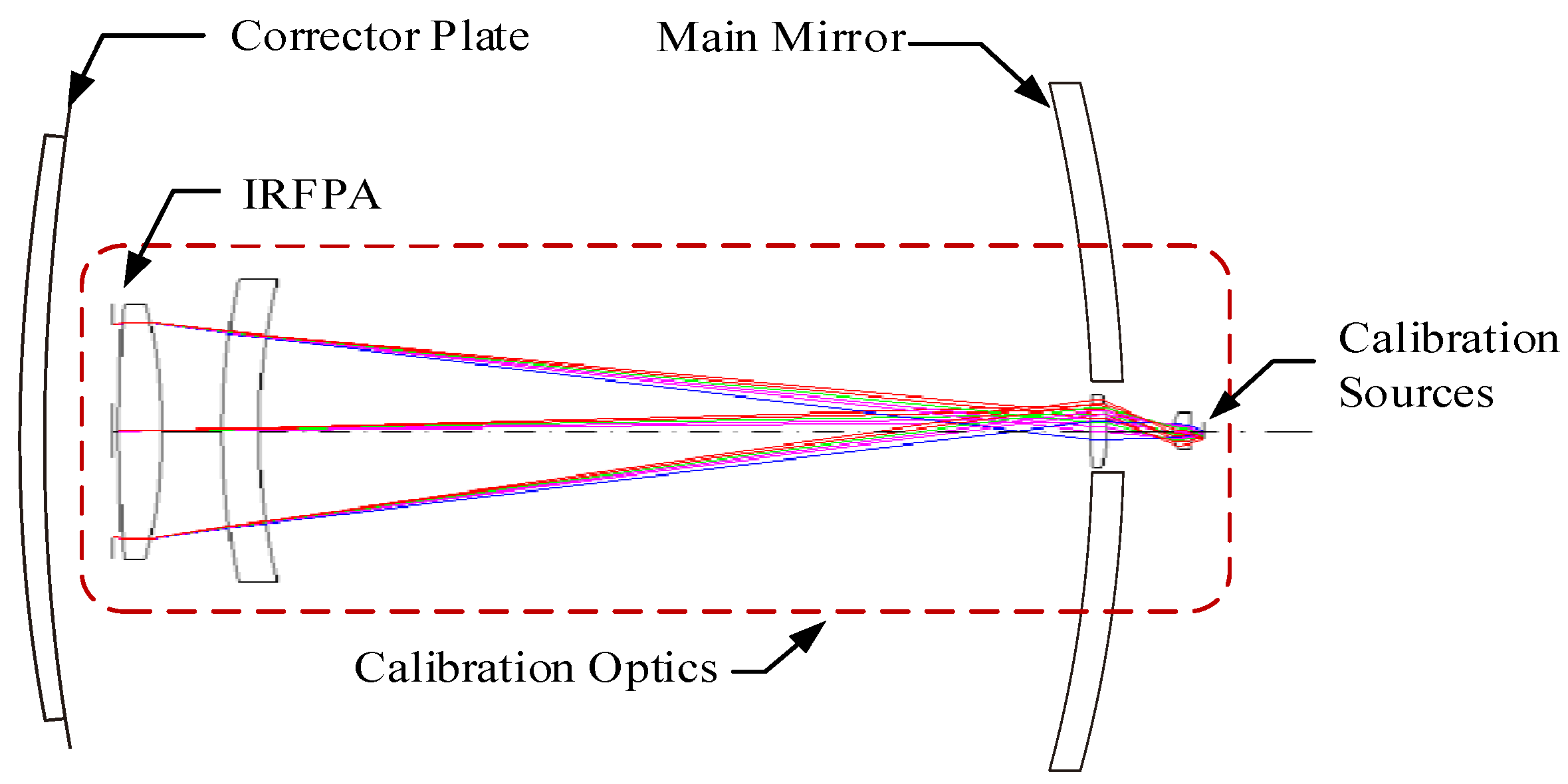
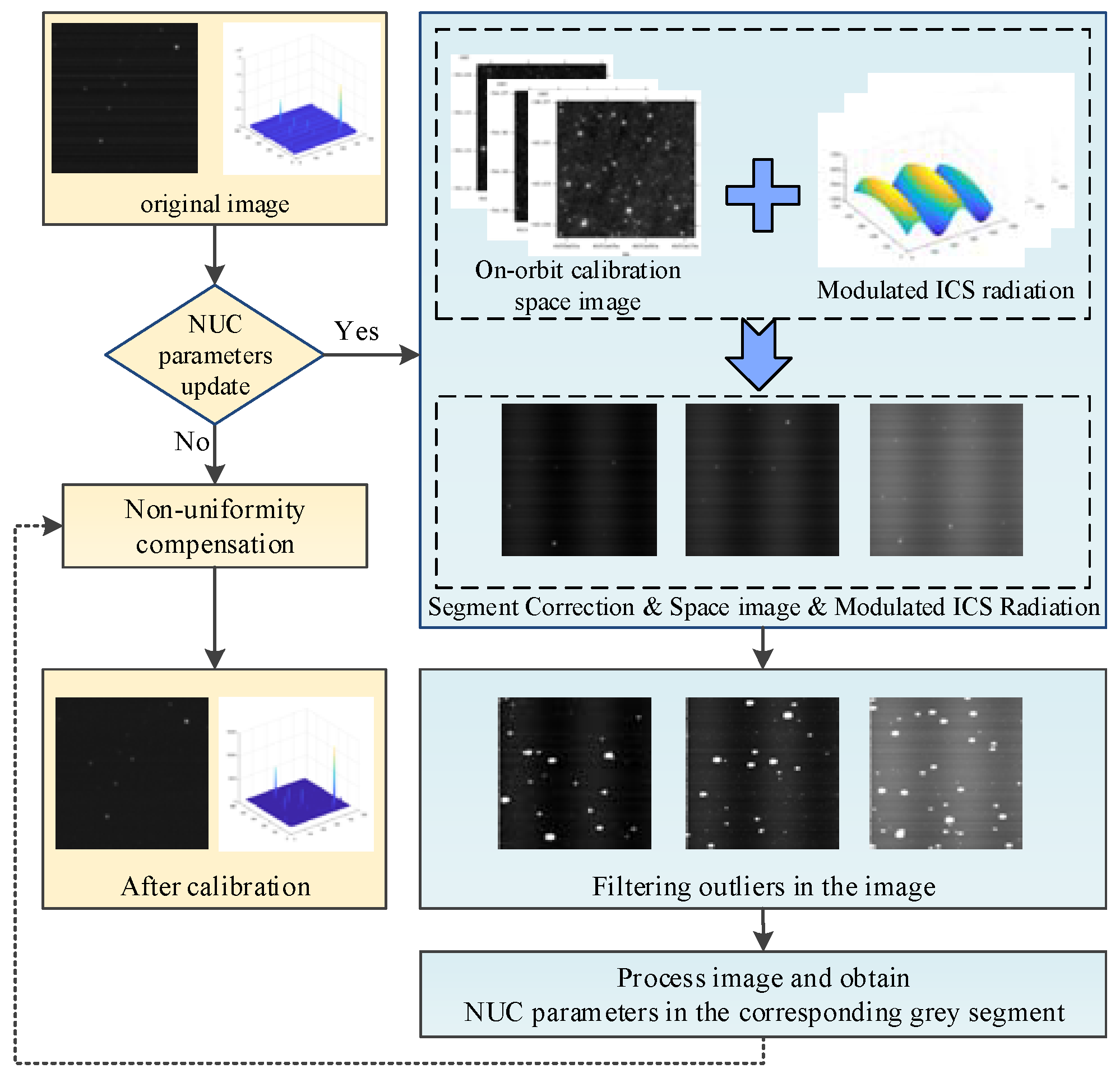
Figure 1 shows a proposed radiometric calibration scheme based on the ICS. The on-board ICS is designed to adjust and control the different grades of radiance. The calibration optics are designed to operate synergistically with the telescope’s optics to produce a uniform and HDR radiance at the IRFPA. In addition, the illumination is combined with the relatively small dynamic space scene radiance acquired through the telescope’s optical path, and these are both projected onto the IRFPA during the calibration process. Thus, a large dynamic range of radiant energy is obtained on the IRFPA during the on-orbit radiometric calibration, which provides the basic radiation for realizing the NUC for each grade of radiance.
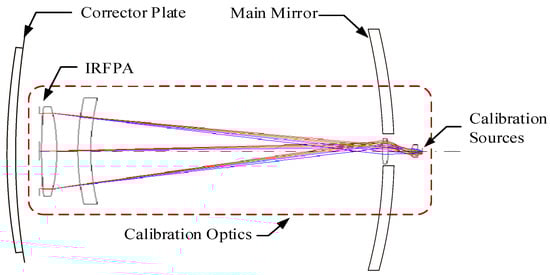
Figure 1.
Schmidt telescope with modulated internal calibration sources (MICS).
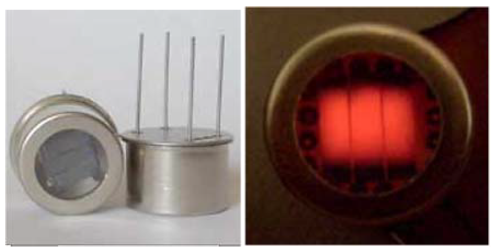
Our internal calibration device design employed a dual-band linear IRFPA. The number of pixels is 2 × 4000 × 12 for 4000-pixel push-broom imaging. The calibration projection area of the IRFPA is 144 mm × 8.6 mm at a central wavelength of short-wave infrared 2.8 μm and medium-wave infrared 4.3 μm. During the calibration procedures, the irradiances at the image plane are from 1.08 × 10⁻⁴ to 8.2 × 10⁻² W/m2 in the short-wave infrared bands, and 1.88 × 10⁻³ to 9.2 × 10⁻² W/m2 in the medium-wave infrared bands. The range of the irradiance is approximately 2 orders of magnitude. The internal calibration source uses a nichrome Helioworks-EF8530 as the calibration black body (Figure 2) [25]. The internal calibration source can operate in the pulsed (modulated) or steady-state mode and consists of three radiating elements. The radiation of each radiating element passes through the calibration optical path to form a substantially uniform illumination on the IRFPA surface. However, approximately 1.5% of the NU remains [26]. The internal calibration source meets requirements associated with temperature stability, repeatability, high precision, HDR, radiance distribution uniformity and other performance indicators and has a short heating and cooling time, small size, low weight, low power consumption and many other advantages.
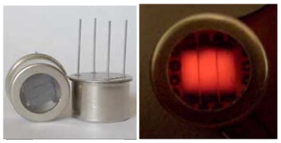
Figure 2.
High-emittance nichrome source EF8530 as a blackbody.
The on-board relative radiometric calibration of the infrared remote sensing system achieves the correction of the IRFPA’s response NU to ensure that high-quality infrared images are obtained around several radiation intensity intervals.
3. Non-Uniformity Correction Method with Modulated Internal Calibration Sources
By considering the characteristics of the infrared remote sensing system and its radiometric calibration, we proposed an on-orbit NUC method for the HDR infrared remote sensing system based on the MICS-NUC method. The modulated illumination (e.g., the dynamic output) provided by the ICS in each grade and the acquired calibration starry scene on-board enable us to obtain a large dynamic sequence image during the on-orbit radiometric calibration. The process filters the image outliers (e.g., relatively bright stars) that violate the statistics assumption due to the unblocking large primary lens. The system can meet the requirements of the SBNUC algorithms in image processing and ensure the effective implementation of the MICS-NUC method. For the sensor’s NU and the illumination’s residual NU in the ICS, the MICS algorithm achieves simultaneous correction by calculating the gain and offset parameters, thus enabling a self-adaptive on-board NUC of the IRFPA.
Figure 3 shows the processing flow chart of the MICS-NUC method. In the following parts, we illustrate the main implementation process of the algorithm.
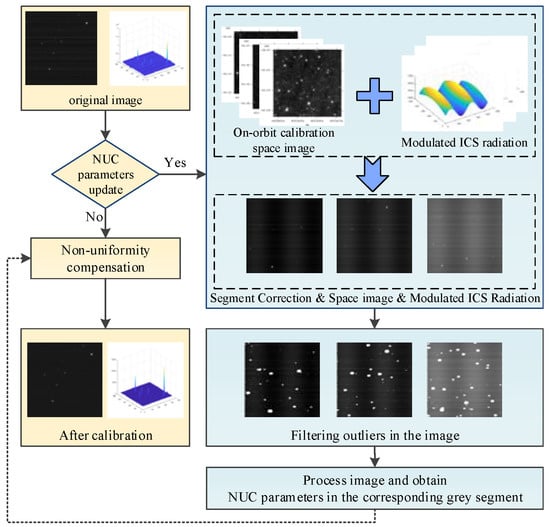
Figure 3.
Processing flow chart of the non-uniformity correction (NUC) method with modulated internal calibration sources.
3.1. Space Scenes Superposition with the Modulated Internal Calibration Source Illumination
In the on-orbit radiometric calibration process, the infrared image obtained by the IRFPA has the following characteristics:
- it contains a small number of bright stars,
- it contains several stars of moderate brightness, and
- it contains a large number of dimmer stars that are distributed almost randomly and that fill in the field of view, which together with the deep-space background form a weak undulating background.
At this point, although the space scene required for the adaptive NUC can be obtained, high-brightness stars are not conducive to HDR calibration, and their influence must be reduced. However, the remaining space scene’s dynamic range can change slightly in the process, and it is challenging to directly obtain different levels of radiation. Thus, we cannot achieve HDR radiometric calibration. Therefore, while obtaining the dynamic space scene, it is also necessary to supplement the corresponding radiation from the on-board calibration device and extend the dynamic range.
Using a modulated ICS with various levels of radiation (even one superposed on the space scene), we can obtain an HDR calibration image during the scan of the IRFPA. This image contains three parts:
- Illuminate the on-board calibration device on the IRFPA so that the radiation uniformity can be supplemented to provide an equivalent radiation output.
- Determine the segmented points and baseline of the radiation: According to the system’s high dynamic range and detection accuracy requirements, the IRFPA’s dynamic range (Rmin, Rmax) is divided into K intervals (Rk−1, Rk) (k = 1, 2, …, K, R0 = Rmin, RK = Rmax). Use the on-board calibration device to provide the reference radiance corresponding to the segmentation interval and obtain the NUC parameters for each segmentation interval. When the IPFPA is in the image capturing process, according to the input radiance from the scene, select the corresponding NUC parameters at each segmentation interval, and complete the corresponding NUC according to the calibration model.
- On-board calibration device modulation output: Within the defined segment, turn on the internal calibration device, set the ICS blackbody to operate in pulse mode, and modulate the reference blackbody in a periodic way (low-to-high or high-to-low changes in the dynamic range of the IRFPA). The device scans across the IRFPA to obtain the periodic changes in the equivalent radiance output (grayscale) on the IRFPA. Finally, a superimposed image of the modulation calibration device and the starry space scene is obtained within the segmentation interval.
This approach shortens the modulation period and facilitates temperature control of the on-board calibration source, thereby improving the calibration accuracy. In addition, this approach reduces the image sequence required by the MICS-NUC algorithm (i.e., it can obtain calibration parameters from a single frame of the space scene) and decreases the time required for radiometric calibration.
3.2. Filter the Image Outliers
The image to be processed by the IRFPA is a radiation-modulated starry image. According to the characteristics of the system (which do not block the entrance pupil), NUC must be performed while the space scene is radiated into the camera. Due to the limitations of the IRFPA’s dynamic range, some bright stars in the deep-space scene do not meet the requirements of the MICS-NUC algorithm and directly affect the estimation of the corrected true value. This fraction of the image points must be filtered out. In addition, the image also contains influencing factors, such as sensor random noise, on-board calibration device illumination NU, and modulation greyscale variation. Therefore, before the calibration parameters are obtained, the filtering method must retain the superimposed modulated radiation in the image while removing the high-irradiance stars and middle-irradiance stars that do not meet the statistical assumptions (such as where the digital number, DN, exceeds the range of the pre-set greyscale segments and other image abnormalities).
The basic idea of the algorithm is as follows. Each point in the image is traversed, a neighborhood Sxy is set for each point, and then the mean and standard deviation of all pixels in the neighborhood are used as local parameters to determine whether the point conforms to the statistical rule. The evaluation method compares the local parameters with the set reasonable thresholds. The point at which the local parameter is less than the threshold is the abnormal point.
The specific steps for using a local threshold-based filtering processing method are as follows. For the scanning of the TDI-IRFPA system, set the way of obtaining an image as the horizontal scanning mode. The neighborhood Sxy is set as the 1 × d area adjacent to the center point, where d = 2r + 1 and r is the number of pixels on both sides of the center point. When the center point is at the border of the image, the outer neighbors are ignored. Let be the modulated space scene acquired by the scanning of the IRFPA, where x = 1, 2, …, M and y = 1, 2, …, N. M is the total number of rows of the scanned image, and N is the total number of columns of the scanned images. Let mxy and σxy denote local parameters. The corresponding local parameter calculation formula at the center point is
Considering the following predicate, an image with outliers can be obtained by determining the point-by-point local parameters of the image and the threshold,
where a and b are the non-negative threshold parameters determined by experiments. In the subsequent process of calculation, the radiance value of the marked point is ignored.
3.3. Determination of Non-Uniformity Correction Parameters in Each Segmentation Interval
Before performing NUC on the IRFPA, it is necessary to analyze the IRFPA’s NU. The internal calibration device is assembled in the infrared remote sensing system. In addition, this configuration also provides the NU of the illumination distribution through the calibration optical system. The NU appears as a low-spatial-frequency FPN with a Gaussian distribution and must be corrected in the NUC algorithm during on-orbit flight. Furthermore, the IRFPA may generate new FPNs according to changes in the operating environment or status, and it is necessary to perform a periodic dynamic NUC. The SBNUC method can meet the requirements. The internal calibration device provides a feasible method for the application of the SBNUC algorithm in the on-orbit radiometric calibration system.
We proposed to obtain the NUC parameters based on the local constant-statistical NUC (LCS-NUC) algorithm. After the scene has been sufficiently random for a certain time, the NU due to the readout electronics is corrected by treating every row of pixels as one channel and normalizing the channel outputs so that each channel produces pixels with the same mean and standard deviation as the median value of the local channels statistics [27,28]. During the IRFPA scan imaging, the modulation output of the internal calibration device and the scene’s radiance change are generated by the same internal standard source. Therefore, after filtering out the image outliers, the mean and standard deviation of the IRFPA naturally meet the requirements of the algorithm for dynamic changes.
According to the IRFPA linear response model, for the linear IRFPA obtained by scanning the size of M × N images, a total of M channels need to be corrected, where N is the number of columns in a scanned image. Assume that the linear IRFPA NUC model is
where and are the gain and offset parameters of the i channel, respectively, is original output image for the IRFPA, and is the output image after NUC for the IRFPA.
First, find the mean and standard deviation for each channel. The statistics for each channel have similar outputs for adjacent channels. The mean and standard deviation of each row of pixels in the image are expressed as
where μ(i) and σ(i) are the mean and standard deviation, respectively, during N columns of scanning the IRFPA for each channel.
Perform median filtering on μ(i) and σ(i) as follows:
where L (an odd number) is the length of the one-dimensional median filter window and is the median filtered output of μ(σ) by the sliding window. The appropriate L is determined by comparison with the performance index beforehand [28]. Thus, we apply the following correction to obtain the estimate of Yi:
The effective gain and offset parameter estimates from Equation (7) are given by
The traditional constant-statistical algorithm is mainly aimed at continuous multi-frame sequences. A single-frame image output is obtained by scanning the linear IRFPA in which each row of pixels is equivalent to the effect of starting the IRFPA consecutive multi-frame sequences, and thus the correction parameters can be obtained within a single frame.
In the process of the IRFPA imaging, the internal calibration device is turned off for imaging and detection. NUC is performed using Equation (4) according to the determined calibration parameters of each interval segment to achieve on-orbit HDR calibration.
4. Verification Test and Results
To verify the processing effectiveness of the MICS-NUC algorithm, the implementation of this algorithm is analyzed and evaluated by simulating the on-board NUC method of the infrared remote sensing system. The verification takes the following steps:
- the system superimposes various influencing factors in the imaging scene based on the star-space scene and generates simulated images for the NUC;
- the system implements the MICS-NUC algorithm on the generated simulated images; and
- we analyze and discuss the NUC results.
4.1. Acquisition of Simulated Images
The simulated NU image is obtained by adding the influencing factors onto the IRFPA during the radiometric calibration process while pointing to a certain area of the space scene. Influencing factors include the ICS illumination NU of a distribution, the sensor FPN, and the sensor random noise.
4.1.1. Space Scenes
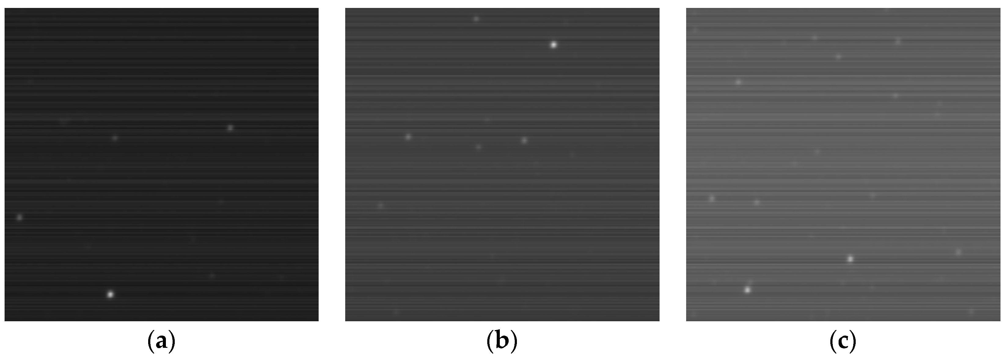
Assuming that the infrared remote sensing system points to the calibration space during the radiometric calibration process and that a small amount of star irradiance exists in the acquired calibration region, we select the actual space scene of the Wide-field Infrared Survey Explorer mission (WISE) in the W2 band (4.36 μm) (NASA/IPAC Infrared Science Archive). The coordinates of the celestial sphere where the image is located are 61.1362, −55.2189 J2000 (Figure 4a,d), 63.5123, −54.5296 J2000 (Figure 4b,e), and 72.9068, −40.0313 J2000 (Figure 4c,f).
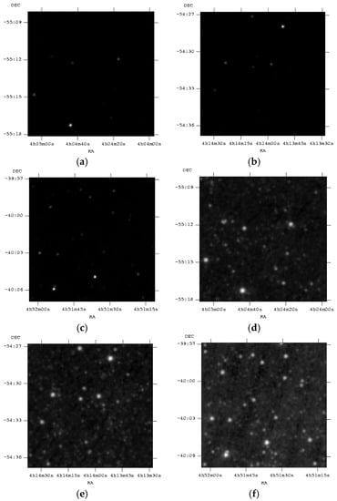
Figure 4.
Actual space scene of the Wide-field Infrared Survey Explorer in the W2 band (4.36 μm): the upper row and lower row figures are the results of linear and logarithmic image compression processing, respectively, of the original space scene. Figure 4 (a,d) are located at 61.1362, −55.2189 J2000; Figure 4 (b,e) are located at 63.5123, −54.5296 J2000; and Figure 4 (c,f) are located at 72.9068, −40.0313 J2000. RA denotes the right ascension, and DEC denotes the declination.
The upper row and lower row figures in Figure 4 are the results of the linear and logarithmic image compression processing, respectively, of the original space scene. The original space scene is a 32-bit flexible image transport system (FITS) format image with a resolution of 436 × 436.
4.1.2. Influence Factors of Radiometric Calibration
Before the simulation process, each influencing factor is added to the original space scene (the following simulated images are all equivalent 14-bit greyscale images). For the channels of IRFPA, the output image of each influencing factor is superimposed on the space scene below K intervals.
where is the illumination NU of the ICS, is the gain NU of the sensor, is the offset NU of the sensor and is the random noise of the sensor.
Assume that follows a Gaussian distribution:
Set the position parameter as μ = 128 and the scale parameter as σ = 410. As a result, the illumination from the ICS causes the radiance at the edge of the IRFPA to be approximately 0.89 times that at the center of the IRFPA.
When the ICS is in the steady-mode, take the ICS equivalent radiance output at 5000 (for example). The ICS radiance distribution is obtained after the scanning of the IRFPA (see Figure 5a). Assume that the sensor gain’s NU follows a Gaussian random distribution with a mean of 1 and a standard deviation of 0.06. The sensor’s offset NU follows a Gaussian random distribution with a mean of 655 and a standard deviation of 370. The sensor’s random noise conforms to a Gaussian random distribution with a mean of 0 and a standard deviation of 10. According to Equation (9), Figure 5b shows the data obtained by superimposing various influential factors and a steady-mode ICS equivalent output at 5000 using a scanning IRFPA.
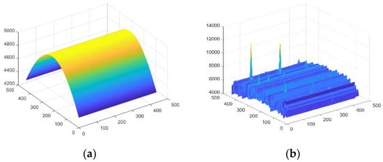
Figure 5.
Data obtained by a scanning infrared focal plane array with a steady-mode internal calibration source output (ICS equivalent output: 5000): (a) steady-mode ICS radiance distribution when the ICS equivalent radiance output is 5000; (b) actual space scene data superposed with a steady-mode ICS output and various influential factors.
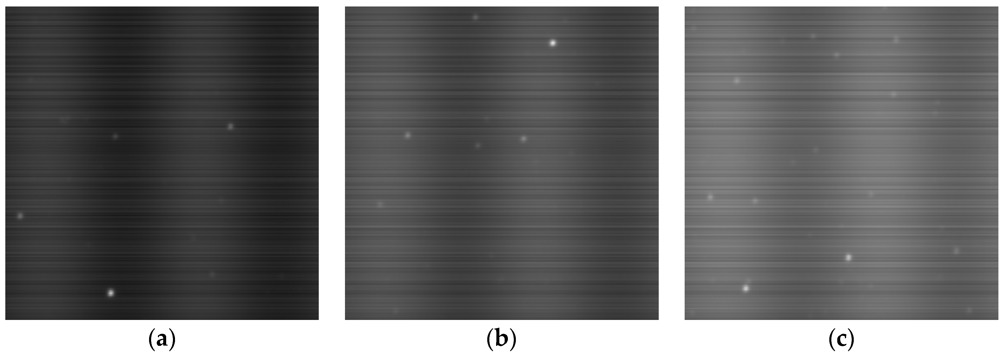
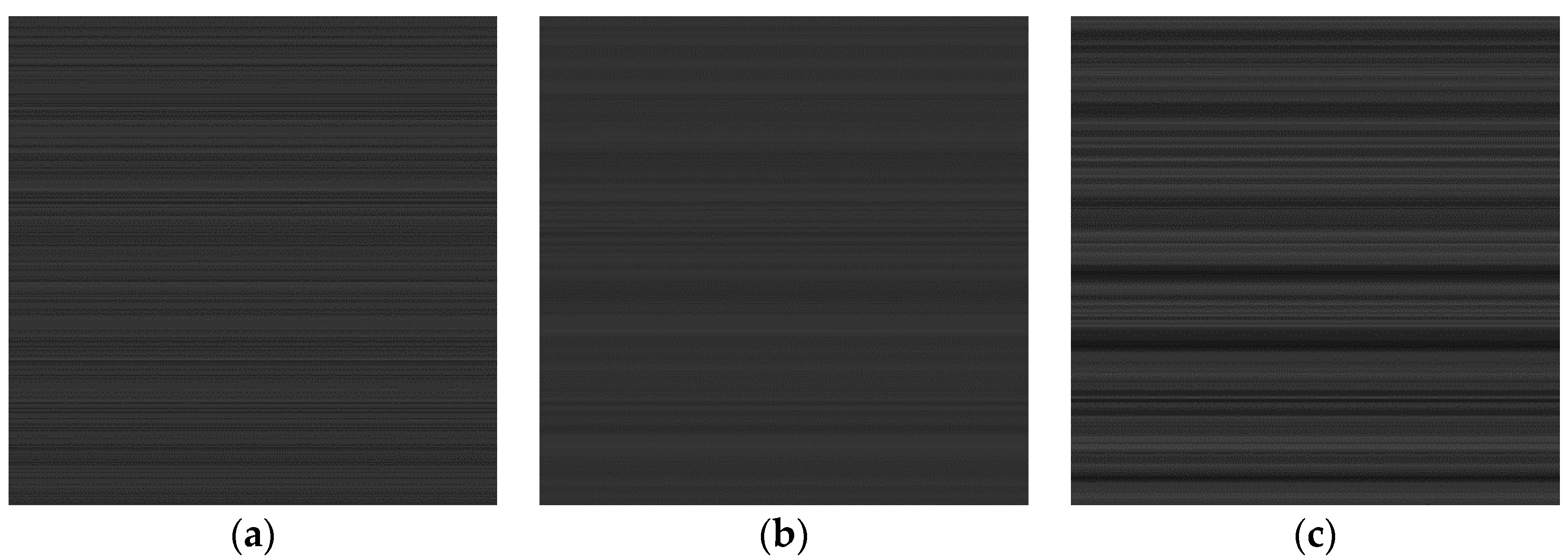
Figure 6 shows the image obtained by superimposing various influential factors and a steady-mode ICS equivalent output at 1000, 3000 and 5000. In the figure, the original space scenes are taken from Figure 4.

Figure 6.
The images obtained before the NUC by superimposing various influence factors and a steady-mode ICS equivalent output at 1000, 3000 and 5000. (a) ICS-1000; (b) ICS-3000; (c) ICS-5000.
4.2. Process and Effects
4.2.1. Segment and Superposed with Modulated Radiation
During the radiometric calibration, the scanning IRFPA can obtain images with the space scene superimposed with a modulated-mode ICS output. These images can conform to the assumption of the MICS-NUC algorithm. First, identify the segmentation point of the equivalent ICS output. Then, set the modulated-mode output of the ICS illumination in the circuit hardware design, such as the sine function modulation output. This output is easier to control assuming that the equivalent radiation intensity A is
where Abase is the baseline reference amplitude, which is set according to the segmentation interval. Astep, the amplitude of the ICS radiation, is combined with the modulation period T so that the output image satisfies the statistical assumption of the MICS-NUC algorithm.
Set Astep as 800 in the modulation image to complete 2 periods within 436 pixels (N columns). Taking the ICS reference amplitude at 5000 as an example, the obtained modulated data are shown in Figure 7a. As a comparison to the steady-mode ICS in Figure 5b, Figure 7b shows the data obtained by superimposing various influential factors and a modulated-mode ICS equivalent output at 5000 using a scanning IRFPA.
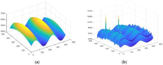
Figure 7.
Data obtained by a scanning IRFPA with a modulated-mode ICS output (ICS equivalent output: 5000): (a) modulated-mode ICS radiance distribution when the ICS equivalent radiance output is 5000; (b) actual space scene data superposed with a modulated-mode ICS output and various influential factors.
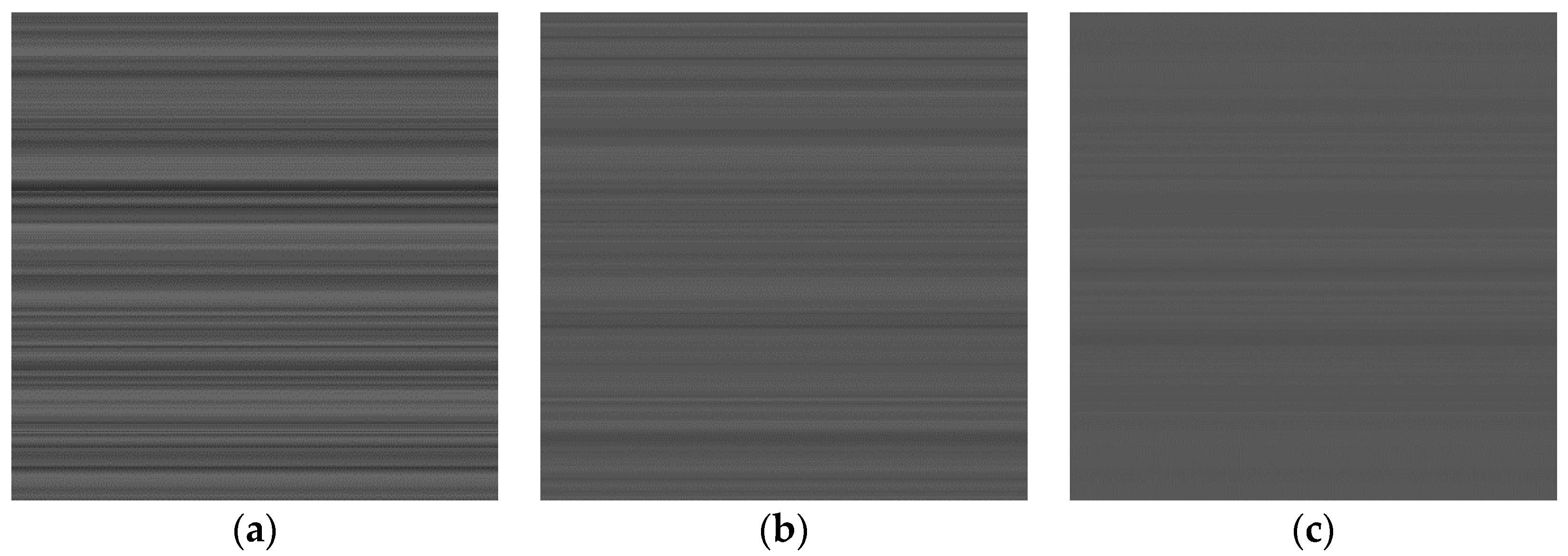
Figure 8 shows the image obtained by the scanning IRFPA after the actual space scene of the corresponding greyscale segment is superimposed on the ICS modulation output (the ICS equivalent reference output Abase is 1000, 3000, and 5000).

Figure 8.
Images obtained before the NUC by superimposing various influence factors and a modulated-mode ICS equivalent output at 1000, 3000 and 5000. (a) ICS-1000; (b) ICS-3000; (c) ICS-5000.
4.2.2. Performing Filter Pre-Treatment on the Image
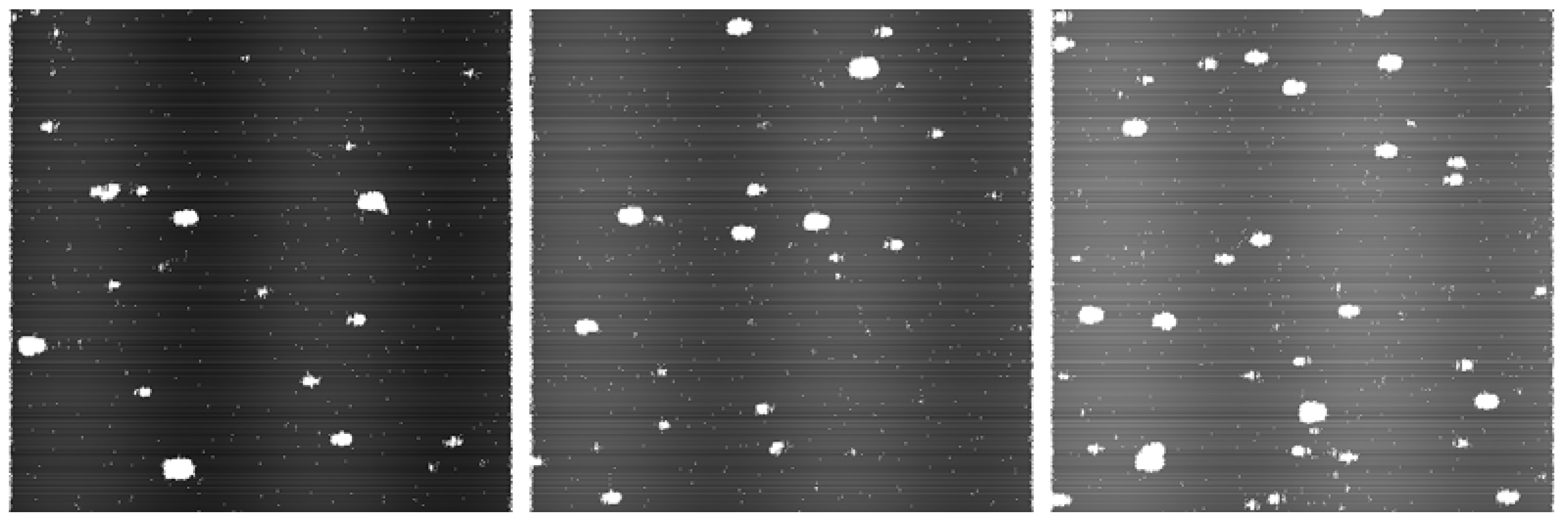
Set the local parameters (the length of the neighborhood d as 9 pixels, a = 30, and b = 100), and perform the filtering processing according to Equation (3). As shown in Figure 9, the outlier in the simulated image Figure 8 is marked. The algorithm can effectively mark most of the stars or nebulas (the white part is an outlier).
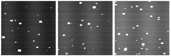
Figure 9.
Figure 8’s outlier is marked during filter processing.
4.2.3. Processing of the Algorithm
This non-uniformity correction algorithm can be used on a single-frame image of the scanning IRFPA output, and the calibration parameters can be obtained in a single-frame. The NUC parameters (i.e., gain and offset parameters) can be obtained after the simulated image is processed by the MICS-NUC algorithm.
The space scene is a non-uniform scene. For evaluating and analyzing the calibration results of the MICS-NUC algorithm, we also simulated a series of test images with the ideal uniform output at the IRFPA. The fixed-pattern noise distribution is the same as that of the simulated images. The test image has the same NUC operation; thus, the change of the test image NU also shows the effect of the MICS-NUC algorithm process. Figure 10 shows two test images with the same FPN distribution as the aforementioned simulation images. The equivalent greyscale output of Figure 10a is 2500, and the NU is 12.99%. In Figure 10b, the equivalent greyscale baseline output is 5000, and the NU is 8.72%.
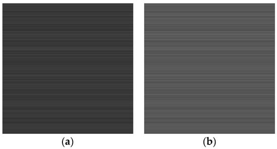
Figure 10.
Evaluation images for the testing process: (a) greyscale baseline equivalent output of 2500, the non-uniformity is 12.99%; (b) greyscale baseline equivalent output of 5000, the non-uniformity is 8.72%.
Note that the non-uniformity (NU) is defined as follows:
where M and N are the number of rows and columns of the IRFPA, respectively; D is the number of dead pixels in the IRFPA, H is the number of overheated pixels in the IRFPA, and Vij is the corresponding pixel out of row i and column j on the IRFPA. Vavg is the average of all effective pixels’ output on the IRFPA. When calculating the sum and NU of the outputs, the values of the invalid pixels are not included.
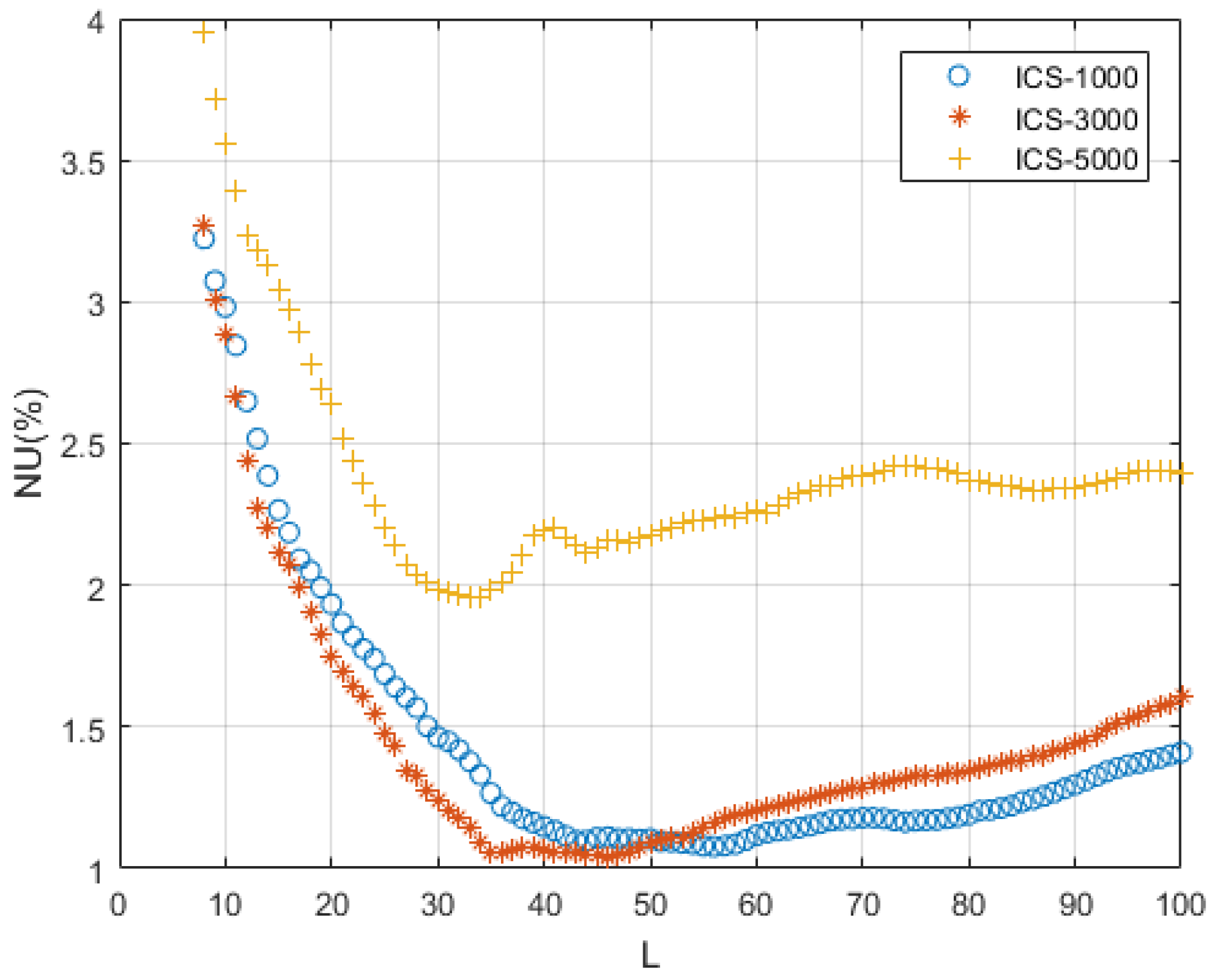
The length of the filter kernel function in the MICS-NUC algorithm is determined by comparing the correction effects in advance. Using the actual space scene superimposed with the modulated ICS output (the ICS equivalent greyscale reference output was 1000, 3000, and 5000), the MICS-NUC algorithm was performed. Figure 11 shows the NUC results of the calibration parameters obtained for the test image 10a using the MICS-NUC algorithm with various filter kernel lengths (L = 8 to 100 pixels). By comparing the NU after the NUC, when the ICS equivalent greyscale reference output is 3000 and L = 35 to 45, the NU is smaller, and the NUC at corresponding greyscale segment can be realized. Therefore, we use L = 35 as the length of the filtering kernel function of the MICS-NUC algorithm.
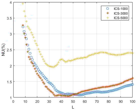
Figure 11.
NUC results of the algorithm with various filtering kernel function lengths L on the test image shown in Figure 10a.
4.3. Non-Uniformity Correction Results
Using the MICS-NUC algorithm, the ICS steady-mode and the ICS modulated-mode outputs were superimposed on the original space scene, and the NUC was applied to the test image of Figure 10 with the same NUC algorithm.
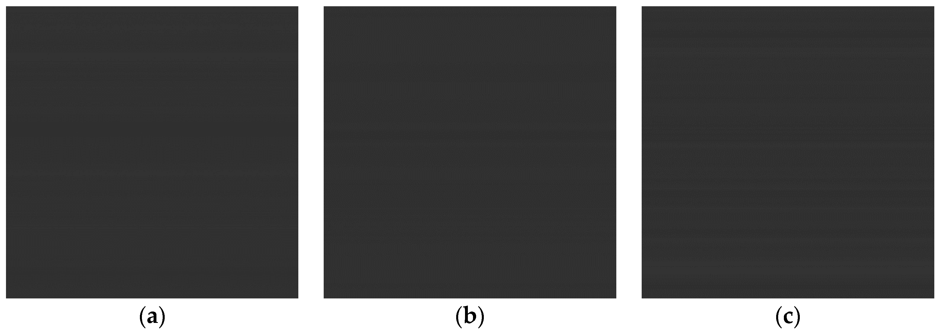
In the ICS steady-mode, first, the original space scene (Figure 4a–c) is superimposed with steady-mode ICS equivalent outputs at 1000, 3000, and 5000, respectively. Secondly, apply the MICS-NUC algorithm to this processed star map to obtain the corresponding three groups of NUC parameters. Finally, the NUC process is performed on the test image based on these correction parameters to obtain a corrected image. The corrected images of Figure 10a with these correction parameters are shown in Figure 12, and the images corrected with the same correction parameters of Figure 10b are shown in Figure 14.
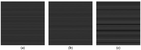
Figure 12.
Correction result image of the evaluation image of Figure 10a with the steady-mode output of various ICS radiation. (a) steady-mode ICS-1000; (b) steady-mode ICS-3000; (c) steady-mode ICS-5000.
Considering that the ICS radiation is in the modulated-mode, only change the superimposed ICS radiation pattern into the modulation output at 1000, 3000, and 5000, respectively. After the same MICS-NUC algorithm processing, the images corrected with these correction parameters of Figure 10a are shown in Figure 13 and the images corrected with these correction parameters of Figure 10b are shown in Figure 15. As a comparison between Figure 12 and Figure 13, as well as Figure 14 and Figure 15, after the MICS-NUC process, the images achieve better uniformity and the image quality is greatly improved.
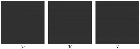
Figure 13.
Correction result image of the evaluation image of Figure 10a with the modulated-mode output of various ICS radiation. (a) modulated-mode ICS-1000; (b) modulated-mode ICS-3000; (c) modulated-mode ICS-5000.
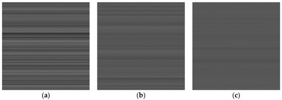
Figure 14.
Correction result image of the evaluation image of Figure 10b with the steady-mode output of various ICS radiation. (a) steady-mode ICS-1000; (b) steady-mode ICS-3000; (c) steady-mode ICS-5000.
Figure 15.
Correction result image of the evaluation image of Figure 10b with the modulated-mode output of various ICS radiation. (a) modulated-mode ICS-1000; (b) modulated-mode ICS-3000; (c) modulated-mode ICS-5000.
5. Discussion
The non-uniformity evaluation results following NUC processing are summarized and shown in Table 1. As indicated in Figure 12, Figure 13, Figure 14 and Figure 15, when the superposed ICS output is in steady-mode, the scene cannot be fully randomized, and the requirements of the SBNUC algorithm cannot be satisfied, making the NUC effect not prominent. However, when the original space scene is superimposed on the ICS modulated-mode output, the FPN is effectively corrected. Furthermore, for different evaluation images with different equivalent radiance, different ICS equivalent reference outputs will provide different results in each mode. For instance, in the space scene represented by Figure 10a, the equivalent radiance DN is 2500. For both modes, an equivalent reference output with DN of 3000 provides the best result. The initial NU of 12.99% is reduced to 5.05% and 1.06% for steady-mode and modulated-mode respectively, as shown in Figure 12b and Figure 13b. Similarly, the space scene represented in Figure 10b has an equivalent radiance DN of 5000. An equivalent reference output with DN of 5000 provides the best result. The initial NU of 8.72% is reduced to 1.90% and 0.79% in the steady-mode and modulated-mode respectively.

Table 1.
Non-uniformity correction results of the evaluation images.
The NUC results in Table 1 prove that the MICS-NUC method is more accurate in estimating the NUC gain and offset parameters following the modulated ICS radiation. In addition, it shows that the segment correction of the MICS-NUC algorithm in Section 4.2.1 is effectual since the NUC parameters obtained in the selected greyscale have a better correction effect than those from other greyscale segments.
To evaluate the MICS-NUC processing effect on the actual space scene, a WISE W2 band (4.36 μm) image (located at 323.841, 1.48141 J2000) is superimposed on the FPN to generate an original image before correction (see Figure 16a). By the MICS-NUC algorithm implementation (the ICS equivalent output is set to 3000, and the ICS is in modulated-mode), calibration parameters are obtained and subsequently the corrected image is obtained (see Figure 16b). As can be seen from Figure 16, the stripe-like and irregular non-uniform noise in the original image is corrected. Note that intensity transformation is implemented to display the corrected image.
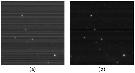
Figure 16.
Implementing the proposed MICS-NUC algorithm to actual space scene. (a) Before NUC; (b) After NUC.
Note that during the MICS-NUC process, only one frame is employed for one group of parameters. The computational load is unquestionably small and the process is straightforward. Furthermore, this approach has various advantages of being highly accurate, highly efficient and self-adaptive. To our best knowledge, the MICS-NUC method, for the first time, fully integrates the system characteristics of a scanning IRFPA into the SBNUC algorithm, providing an effective solution for the NUC of large-aperture high dynamic range on-orbit remote sensing systems. The MICS-NUC algorithm allows the system to periodically implement on-orbit dynamic corrections and update the radiometric calibration parameters, which ensures on-orbit high-quality imaging in a large time scale.
The proposed NUC method in this paper is designed for the remote sensing system operating in the narrower non-atmospheric window band. This kind of scene-based NUC algorithm is also suitable for typical earth imaging thermal remote sensing systems. For a scene that is constantly changing, the correction result should be better. However, the application of different types of scene-based NUC algorithms is conditional to the characteristics of the scene. At present, most scene-based NUC algorithms have been applied to thermal imaging systems with small array sensors. Since most of the scene-based NUC algorithms are highly complex and require real-time image processing performance, the application of these algorithms to space-based platforms with large array detectors is still in the experimental stage.
Regarding the calibration accuracy, there are several ways to improve this, such as further improvement of the internal calibration sources control and optimization of the calibration optics and the NUC algorithm. A comprehensive discussion on the calibration accuracy is beyond the scope of this paper.
6. Conclusions
To solve the problem of infrared remote sensing NUC without blocking the field of view, we have developed a MICS-NUC method. The method implements the algorithm’s steps, including the segmentation, space scene and modulated ICS image acquisition method, the variable threshold function of filtering outliers, the local constant-statistical NUC method and other algorithm implementation steps, to achieve IRFPA on-orbit HDR dynamic self-adaptive NUC. This approach can avoid several problems, such as scene sequence images dissatisfying the algorithm’s assumption under special conditions on the platform and large-aperture telephoto systems that cannot be effectively blocked. The verification with the simulated image shows that the NU of the IRFPA is greatly reduced. Compared to other on-board NUC methods requiring referenced blackbodies (CBNUC methods), this algorithm has the advantages relating to its self-adaptiveness, system miniaturization, and cost savings. We believe the implementation of this calibration method will meet the new high-tech requirements of remote sensing systems in meteorology, defense and plenty of other fields.
Author Contributions
Y.S. and X.D. contributed to this work in designing and performing the research. W.J. and F.Z. contributed to the validation. X.W., F.M. and S.X. contributed to the comparisons and proofread.
Funding
This work was supported by the 13th Five-Year Plan Pre-study Foundation of the Army Armament Department of China (No. 3010204004104).
Acknowledgments
This research has made use of the NASA/ IPAC Infrared Science Archive, which is operated by the Jet Propulsion Laboratory, California Institute of Technology, under contract with the National Aeronautics and Space Administration. http://irsa.ipac.caltech.edu/applications/wise/. Authors are thankful to JPL NASA for providing IR images.
Conflicts of Interest
The authors declare no conflict of interest.
References
- Garlick, D.S.; Greenman, M.E.; Larsen, M.F.; Sargent, S.D.; Hansen, J.S. Algorithms for calibration and point-source extraction for a LWIR space-based sensor. In Signal and Data Processing of Small Targets; International Society for Optics and Photonics: Orlando, FL, USA, 1996; pp. 182–194. [Google Scholar]
- Bartschi, B.Y.; Morse, D.E.; Woolston, T.L. The Spatial Infrared Imaging Telescope III. Johns Hopkins APL Tech. Dig. 1996, 17, 215–225. [Google Scholar]
- Andreas, N.S. Space-Based Infrared System (SBIRS) system of systems. In Proceedings of the Aerospace Conference, Snowmass at Aspen, CO, USA, 13 February 1997; pp. 429–438. [Google Scholar]
- Mooney, J.M.; Shepherd, F.D. Characterizing IR FPA nonuniformity and IR camera spatial noise. Infrared Phys. Technol. 1996, 37, 595–606. [Google Scholar] [CrossRef]
- Black, W.T.; Tyo, J.S. Feedback-integrated scene cancellation scene-based nonuniformity correction algorithm. J. Electron. Imaging 2014, 23, 023005. [Google Scholar] [CrossRef]
- Tansock, J.; Bancroft, D.; Butler, J.; Cao, C.; Datla, R.; Hansen, S.; Helder, D.; Kacker, R.; Latvakoski, H.; Mylnczak, M.; et al. Guidelines for Radiometric Calibration of Electro-Optical Instruments for Remote Sensing; Space Dynamics Lab Publications: Logan, UT, USA, 2015. [Google Scholar]
- Jin, W.; Liu, C.; Xiu, J. Infrared nonuniformity correction and radiometric calibration technology using U-shaped blackbody. In International Symposium on Photoelectronic Detection and Imaging; International Society for Optics and Photonics: Beijing, China, 2011; pp. 819405–819409. [Google Scholar]
- Jin, M.; Jin, W.; Li, Y.; Li, S. An evaluation method based on absolute difference to validate the performance of SBNUC algorithms. Infrared Phys. Technol. 2016, 78, 1–12. [Google Scholar] [CrossRef]
- Barsi, J.; Schott, J.; Hook, S.; Raqueno, N.; Markham, B.; Radocinski, R. Landsat-8 Thermal Infrared Sensor (tTIRS) Vicarious Radiometric Calibration. Remote Sens. 2014, 6, 11607–11626. [Google Scholar] [CrossRef]
- Datla, R.; Shao, X.; Cao, C.; Wu, X. Comparison of the calibration algorithms and si traceability of MODIS, VIIRS, GOES, and GOES-E RABI sensors. Remote Sens. 2016, 8, 126. [Google Scholar] [CrossRef]
- Montanaro, M.; Lunsford, A.; Tesfaye, Z.; Wenny, B.; Reuter, D. Radiometric calibration methodology of the Landsat 8 Thermal Infrared Sensor. Remote Sens. 2014, 6, 8803–8821. [Google Scholar] [CrossRef]
- Montanaro, M.; Levy, R.; Markham, B. On-Orbit Radiometric Performance of the Landsat 8 Thermal Infrared Sensor. Remote Sens. 2014, 6, 11753–11769. [Google Scholar] [CrossRef]
- Huo, L.; Zhou, D.; Wang, D.; Liu, R.; He, B. Staircase-scene-based nonuniformity correction in aerial point target detection systems. Appl. Opt. 2016, 55, 7149–7156. [Google Scholar] [CrossRef] [PubMed]
- Black, W.T.; Tyo, J.S. Improving feedback-integrated scene cancellation nonuniformity correction through optimal selection of available camera motion. J. Electron. Imaging 2014, 23, 053014. [Google Scholar] [CrossRef]
- Hayat, M.M.; Torres, S.N.; Armstrong, E.; Cain, S.C.; Yasuda, B. Statistical algorithm for nonuniformity correction in focal-plane arrays. Appl. Opt. 1999, 38, 772–780. [Google Scholar] [CrossRef] [PubMed]
- Zuo, C.; Chen, Q.; Gu, G.; Sui, X.; Qian, W. Scene-based nonuniformity correction method using multiscale constant statistics. Opt. Eng. 2011, 50, 087006–087011. [Google Scholar] [CrossRef]
- Harris, J.G. Nonuniformity Correction of Infrared Image Sequences Using the Constant-Statistics Constraint. IEEE Trans. Image Process. 1999, 8, 1148–1151. [Google Scholar] [CrossRef] [PubMed]
- Zhang, C.; Zhao, W. Scene-based nonuniformity correction using local constant statistics. JOSA A 2008, 25, 1444–1453. [Google Scholar] [CrossRef] [PubMed]
- Hardie, R.C.; Baxley, F.; Brys, B.; Hytla, P. Scene-Based Nonuniformity Correction with Reduced Ghosting Using a gated LMS Algorithm. Opt. Express 2009, 17, 14918–14933. [Google Scholar] [CrossRef] [PubMed]
- Scribner, D.A.; Sarkady, K.A.; Caulfield, J.T.; Kruer, M.R.; Katz, G.; Gridley, C.; Herman, C. Nonuniformity correction for staring ir focal plane arrays using scene-based techniques. In Applications of Artificial Neural Networks; International Society for Optics and Photonics: Orlando, FL, USA, 1990; pp. 224–233. [Google Scholar]
- Hardie, R.C.; Hayat, M.M.; Armstrong, E.; Yasuda, B. Scene-based nonuniformity correction with video sequences and registration. Appl. Opt. 2000, 39, 1241–1250. [Google Scholar] [CrossRef] [PubMed]
- Kintner, E.C.; Jacobs, E.S.; Hartley, J.M.; Cucchiaro, P.J.; Wall, L. Infrared Internal Calibration Sources developed at SSGPO, inc. In Infrared Spaceborne Remote Sensing; International Society for Optics and Photonics: San Diego, CA, USA, 2003; pp. 42–50. [Google Scholar]
- Kintner, E.C.; Hartley, J.M.; Jacobs, E.S.; Cucchiaro, P.J. Advanced development of internal calibration sources for remote sensing telescopes. In Infrared Spaceborne Remote Sensing; International Society for Optics and Photonics: Denver, CO, USA, 2004; pp. 313–319. [Google Scholar]
- Kintner, E.C.; Wong, W.K.; Jacobs, E.S.; Cucchiaro, P.J.; Koshel, R.J. Efficient and versatile internal reference sources for remote sensing space telescopes. In Infrared Spaceborne Remote Sensing; International Society for Optical Engineering: San Diego, CA, USA, 2006; p. 62970F. [Google Scholar]
- Helioworks. Pulsable IR Source: Model EF-8530. Available online: https://helioworks.com/wp-content/uploads/2016/08/EF-8530.pdf (accessed on 20 October 2017).
- Sheng, Y.; Jin, W.; Dun, X.; Zhou, F.; Xiao, S. A design of an on-orbit radiometric calibration device for high dynamic range infrared remote sensors. In AOPC 2017: Space Optics and Earth Imaging and Space Navigation; International Society for Optics and Photonics: Beijing, China, 2017; p. 104631N. [Google Scholar]
- Cao, Y.; Jin, W.; Liu, C.; Liu, X. Adaptive nonuniformity correction and hardware implementation of IRFPA. Opt. Precis. Eng. 2011, 19, 2985–2991. [Google Scholar]
- Sui, J.; Jin, W.; Dong, L.; Wang, X. A new non-uniformity correction algorithm for infrared line scanners. In Defense and Security Symposium; International Society for Optics and Photonics: Orlando, FL, USA, 2006; pp. 62070Y–62078Y. [Google Scholar]


© 2018 by the authors. Licensee MDPI, Basel, Switzerland. This article is an open access article distributed under the terms and conditions of the Creative Commons Attribution (CC BY) license (http://creativecommons.org/licenses/by/4.0/).