Physical Modeling of Hydrodynamics, Pore-Water Pressures, and Local Scour in a Sandy Seabed Around Pile Groups Under Regular Wave–Current and Irregular Wave Loading

 , , , , , , and
Abstract
1. Introduction
2. Experimental Design
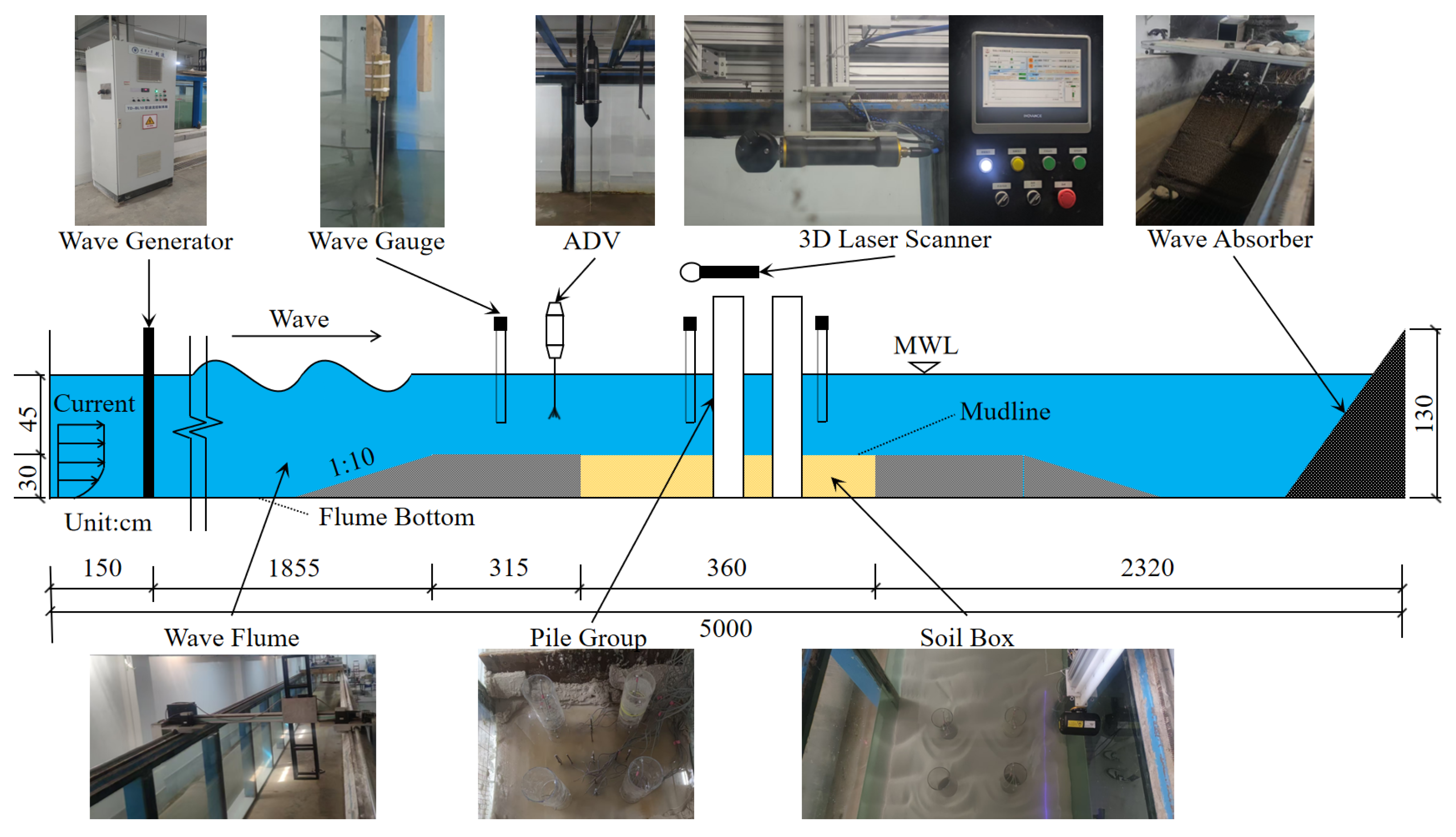
2.1. Experimental Facility
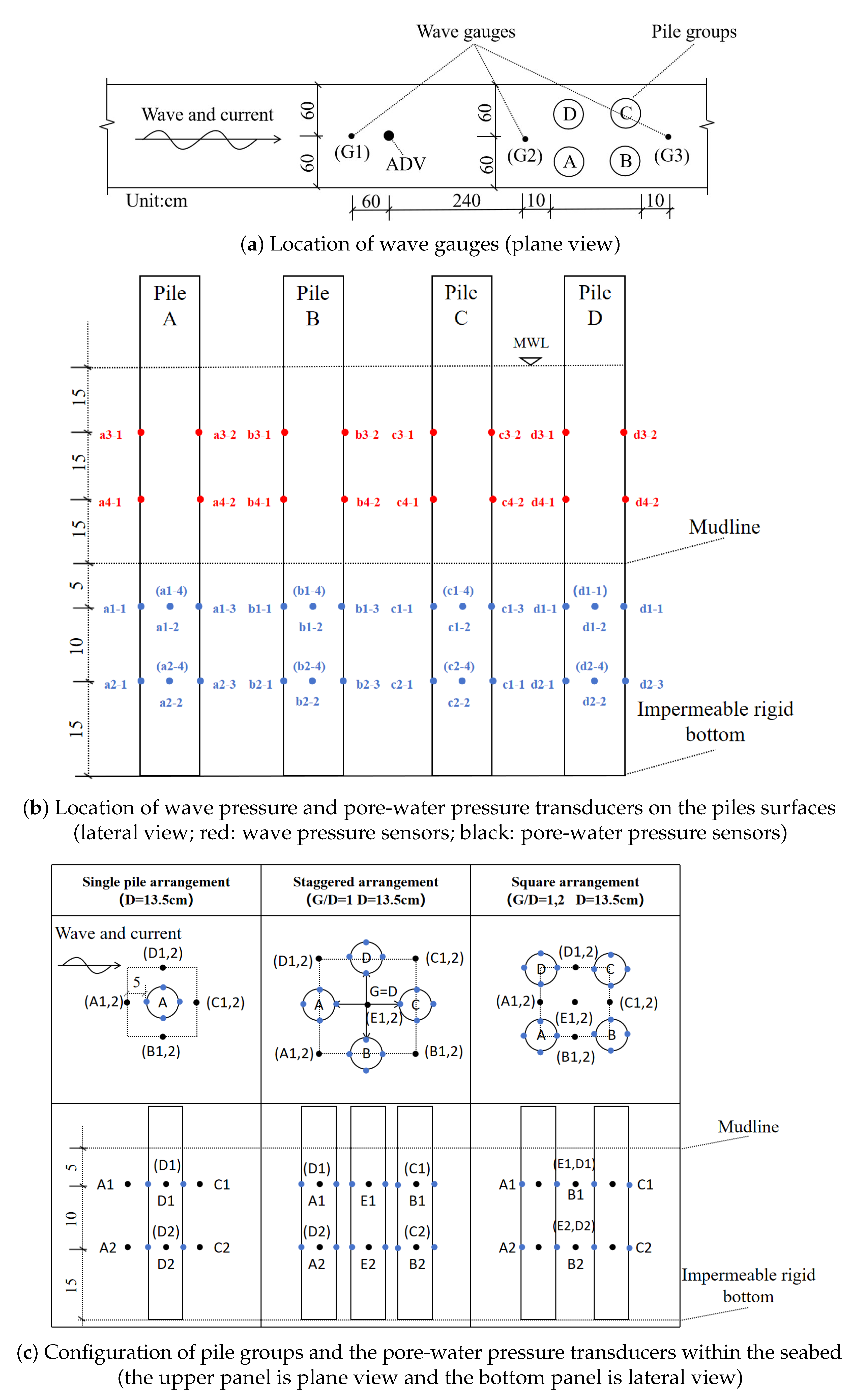
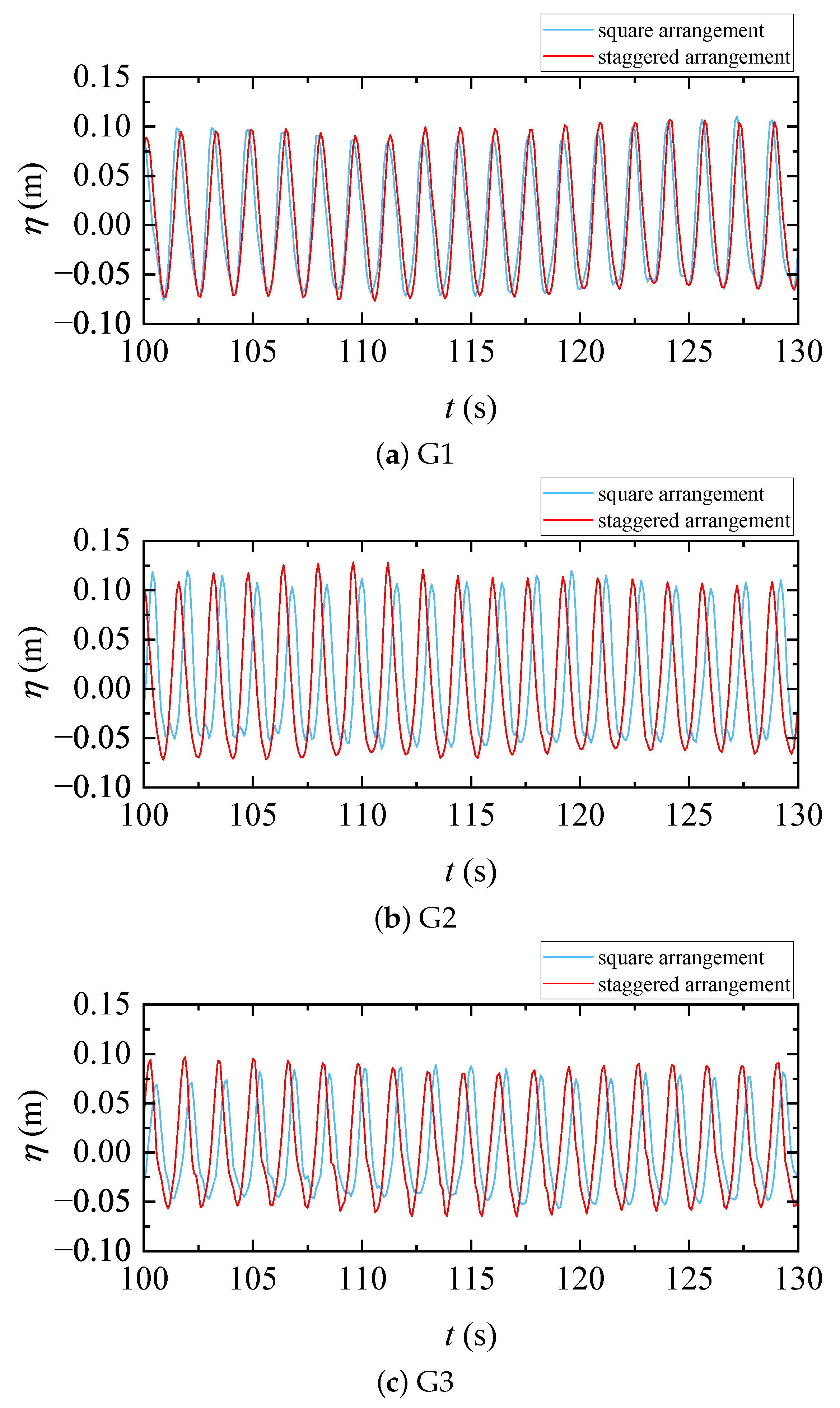
- Wave gauges: Three wave gauges (G1, G2, and G3; Model YWS200-WXX, Chengdu Yufan Technology Co., Ltd., Chengdu, China) were installed to measure the elevation of the water surface in time, as shown in Figure 3a. These wave gauges have a measurement range of 0–0.60 m and an accuracy of ±0.5%. The G1 wave gauge was positioned to measure the height of the incident wave, while other G2 and G3 wave gauges were placed 10 cm upstream and downstream of the pile model, respectively.
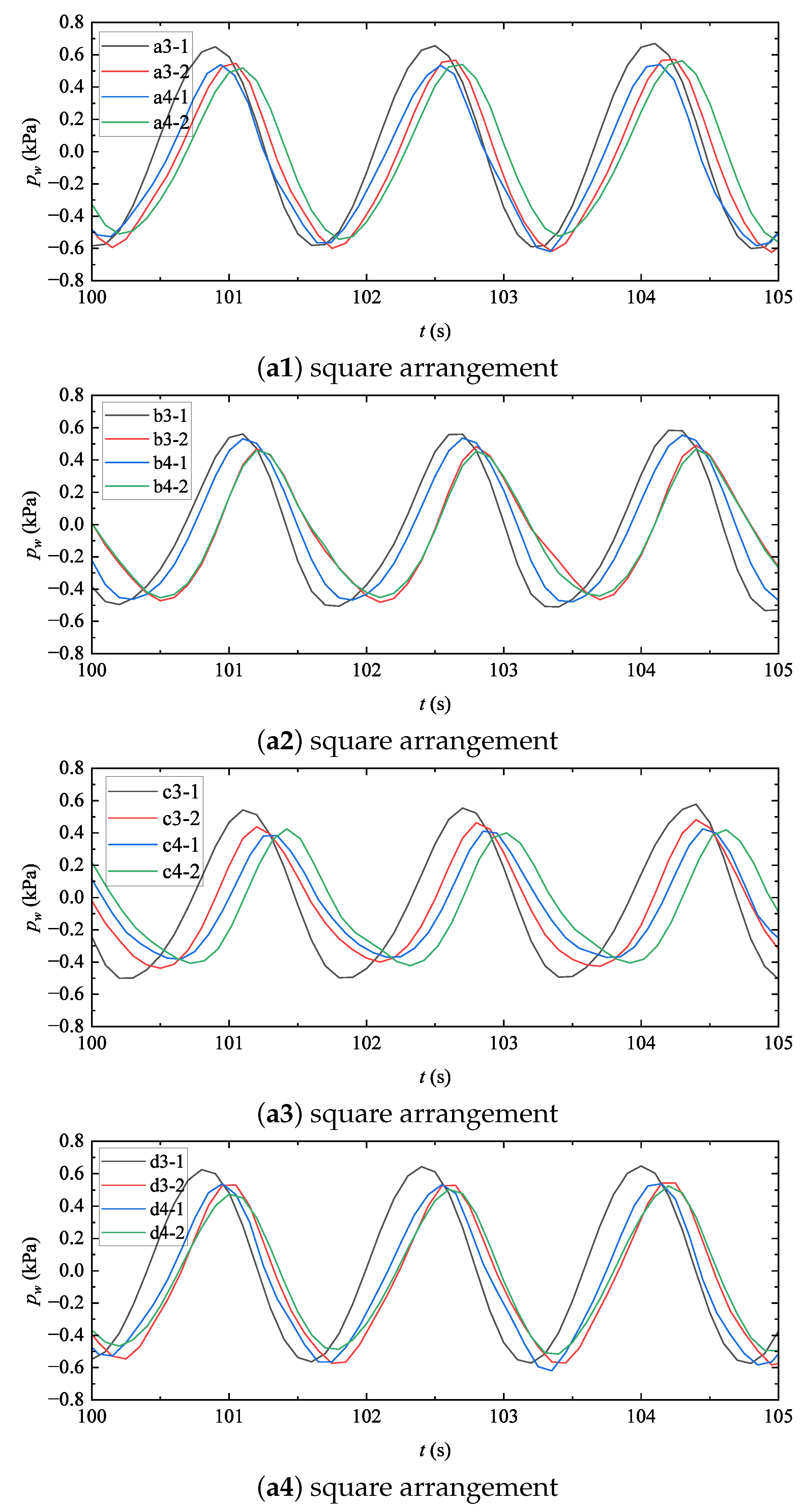
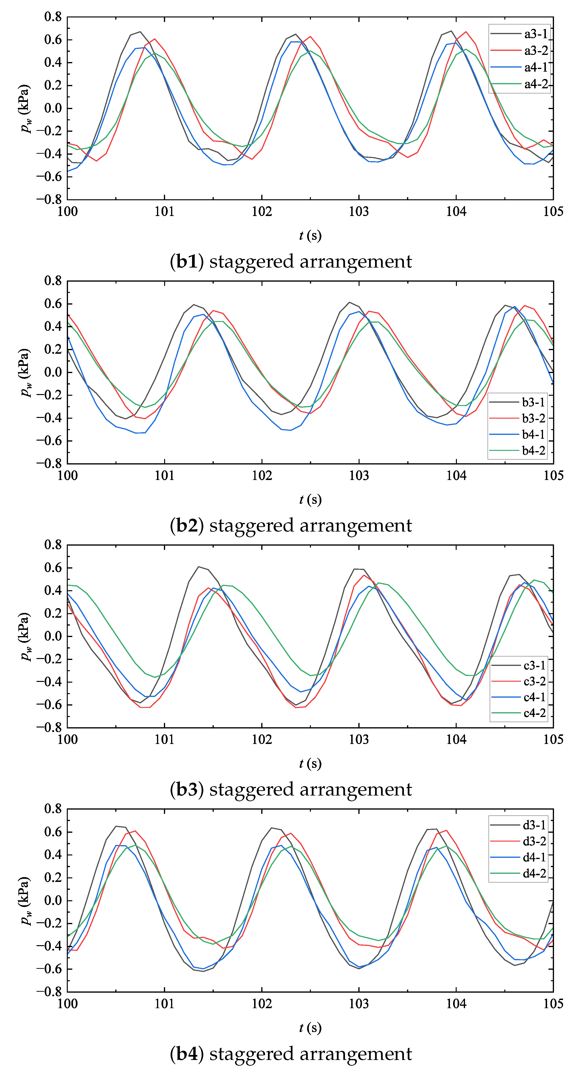
- Wave pressure transducers: Sixteen wave pressure sensors (model CY302, Chengdu Dasheng Yingji Co., Ltd., Chengdu, China; points a3-1 to d4-2) were mounted on the pile surface to measure dynamic wave pressures. These transducers have an outer diameter of 6 mm, a measurement range of 0–20 kPa, and a precision of ±0.01%. As shown in Figure 3b, they were arranged in vertical intervals of 15 cm on both the upstream and downstream sides, starting 15 cm above the surface of the seabed.
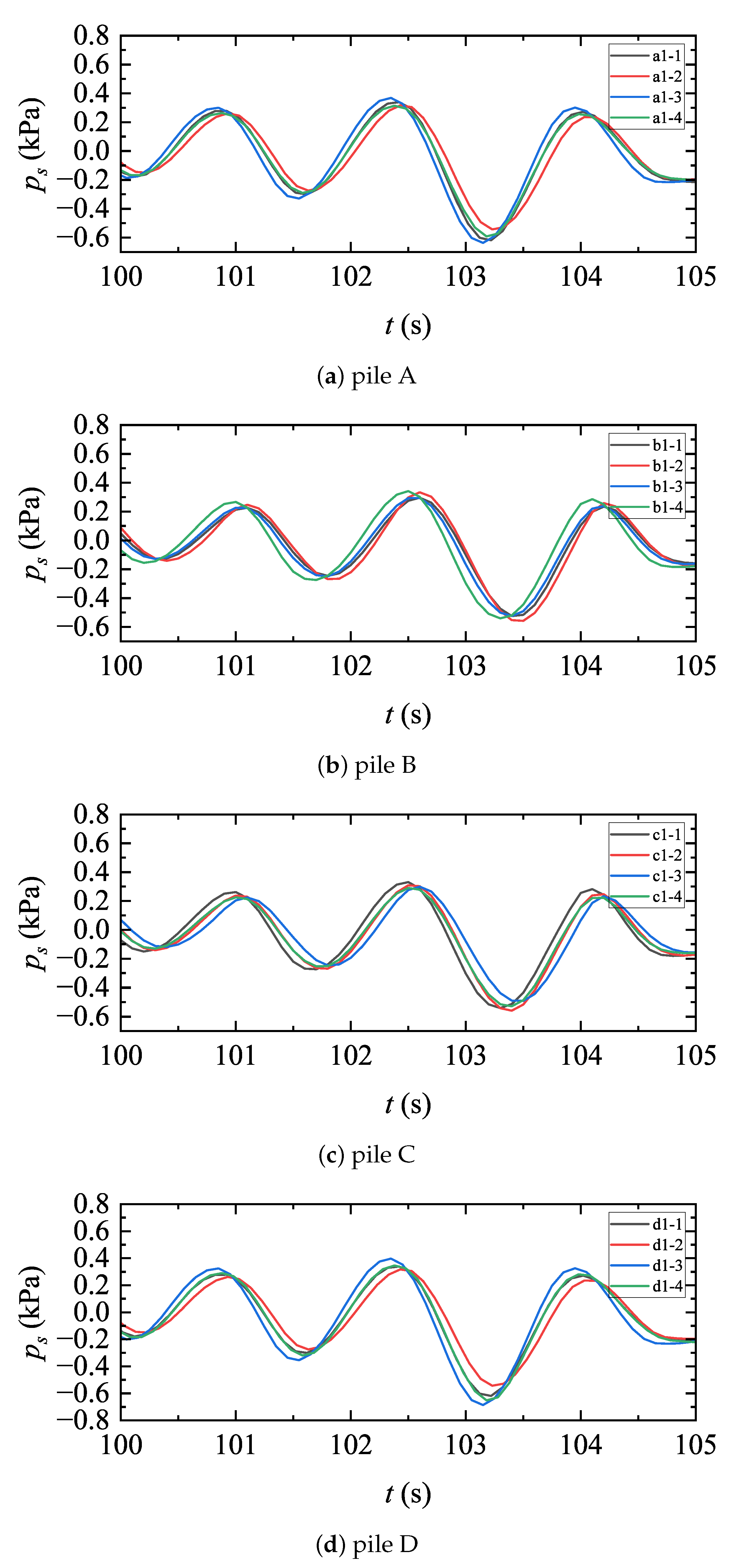
- Pore-water pressure transducers: A total of forty-two pore-water pressure transducers (model CY303, Chengdu Dasheng Yingji Co., Ltd., Chengdu, China) were used to monitor pore-water pressure within the seabed, as shown in Figure 3b. The pore-water pressure transducers have an outer diameter of 8 mm, a measurement range of 0–30 kPa, and an accuracy of ±0.01%. The arrangement consists of the following: (1) ten sensors embedded within the seabed in the gaps between piles, distributed across two layers at depths of 5 cm and 15 cm (denoted as Ai, Bi, Ci, Di and Ei, for which “i” is 1 or 2, referring to the first layer or the second layer); (2) thirty-two sensors mounted on the pile surfaces, arranged in two layers with four sensors per layer, spaced 10 cm apart vertically (denoted as ai–j, bi–j, ci–j, di–j, for which “i” is a similar index to that above, referring to two layers on the pile surface, while “j” is 1, 2, 3 or 4, referring to four different sensors within the same layer). The arrangement is employed to capture the distributions of the pore-water pressures in both horizontal and vertical directions, which has not been carried out in most previous experimental studies due to the limited number of transducers used [23,30,31].
- ADV: An Acoustic Doppler Velocimeter (ADV, Nortek AS, Norway; range—±1.4 m/s; accuracy—±0.5% of the measured value plus ±1 mm/s) was used to measure current velocity .
- Three-dimensional laser scanner: A GoPro camera was used to record the progress of the scouring process. To quantify topographic changes, the sand bed was leveled prior to each test. Following each scouring event, an underwater 3D laser scanner was mounted. The scanner (Model—Insight Nano, Voyis company, Canada; scanning range—0.13–1.0 m; accuracy—0.3 mm in the x- and y-directions, respectively, 0.1 mm in the z-direction, when the water depth is less than 0.5 m) was used to scan and record the seabed morphology.
2.2. Soil Sample
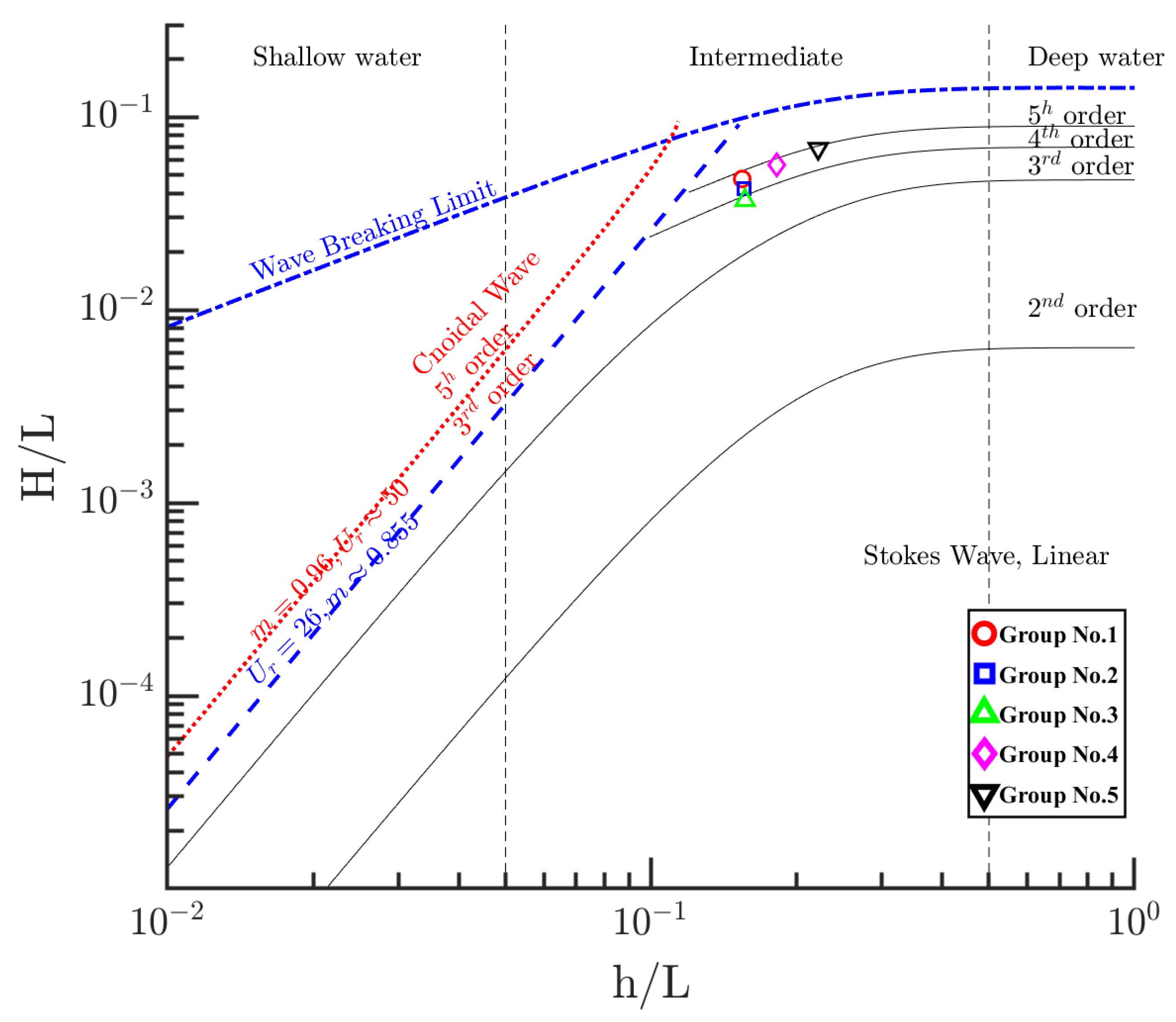
2.3. Hydrodynamic Conditions
2.4. Experimental Procedure
- (1)
- Transducer layout and preprocessing: As shown in Figure 3a, four pile foundation models were placed at the center of the flume, avoiding interference from the flume walls. Instrumentation ports were pre-drilled on the surface of each pile to accommodate wave pressure and pore-water pressure transducers. Ten pore-water pressure transducers were fixed to steel brackets and buried in the seabed at specified depths. A wooden frame was erected above the flume to mount three wave gauges at their designated calibration positions. To ensure data accuracy, all transducers were soaked for at least 24 h prior to the removal of air bubbles and to prevent signal distortion.
- (2)
- Sediment filling and bed preparation: Following the calibration and placement of the piles and transducers, the sediment pit was filled. Pre-screened quartz sand was gradually added in batches to minimize impact forces that could cause transducer displacement or pile tilting. Once filled, water was slowly introduced to submerge the sand bed. The tank was then left to stand for at least 24 h to ensure the complete consolidation of a sandy bed. Upon full consolidation, the sand bed was leveled with a scraper, ensuring that the area around the test piles was at the same level as the entire sand tank.
- (3)
- Water filling: After seabed consolidation, a secondary injection of water was performed. The flow rate was strictly controlled using low-velocity pumping to prevent rapid currents from scouring the seabed or inducing morphological changes. Injection continued until the water level rose to 0.45 m above the bed surface. The subsequent step commenced after the water surface stabilized naturally.
- (4)
- Initiation of wave and current generation: Once the water surface was stable without observable fluctuations, the wave maker and current generation systems were activated according to the design parameters required for the specific test conditions.
- (5)
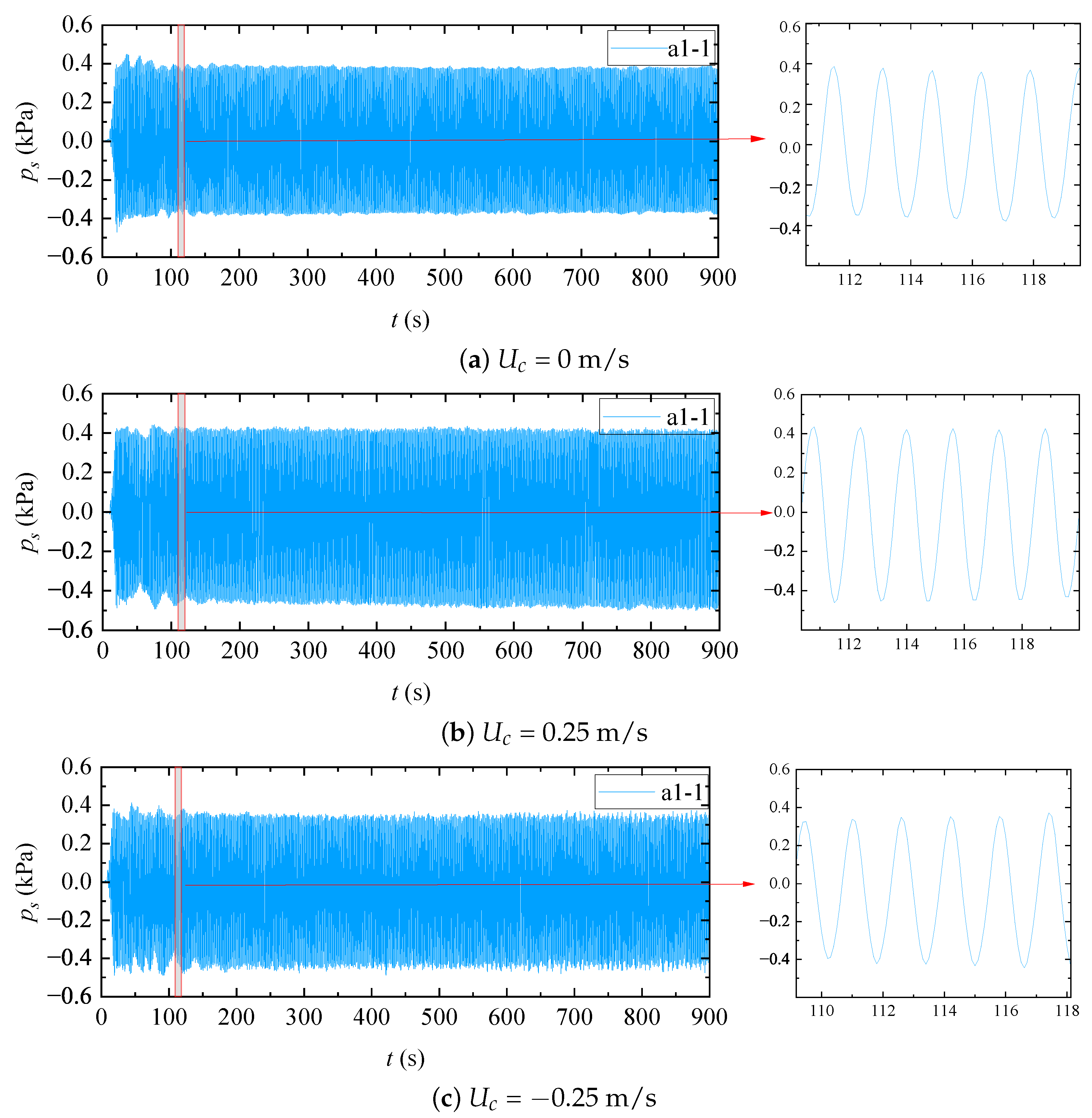
- Data acquisition: Synchronized through activating the wave generator, the data acquisition system was triggered for all transducers. The sampling frequency was uniformly set to 10 Hz for all measurement instruments, including wave gauges, wave pressure sensors, and pore-water pressure transducers. Data transmission was monitored in real time to ensure that there was no loss of data or anomalies. For each test condition, the total duration was 2 h. To minimize the accumulation of wave reflection due to long-term continuous wave generation and to allow scour scanning, the test was divided into eight consecutive runs, each lasting 15 min. At the end of each run, wave generation was stopped and a high-resolution scan of the seabed morphology was performed. This procedure was applied consistently to all experimental cases. In the experimental design phase, considering that a 2-h acquisition period would lead to redundant data processing and be constrained by storage capacity, the sampling frequency was set to 10 Hz.
- (6)
- Seabed morphology scanning: After hydrodynamic loading ceased, the 3D laser scanner was positioned over the measurement area to perform a full-scale scan of the sand bed around the pile groups. Scanner calibration parameters, such as the resolution and scanning range, were pre-configured. The movement speed of the scanner was kept constant, strictly adhering to a pre-set trajectory to ensure data continuity and accuracy. Once the scan was completed and any data gaps were addressed, the scanner was returned to its initial position, and equipment checks were performed in preparation for the next run.
- (7)
- Multi-condition test cycle: Under the same test conditions, steps (4)–(7) were repeated to obtain multiple datasets to improve the reliability and repeatability of the results. When switching to a new test condition, the entire procedure from steps (1)–(7) was re-executed, including transducer re-deployment, seabed leveling, and water level adjustment. This ensured that each test condition remained independent and met the specific design requirements.
2.5. Experimental Uncertainties and Scaling Considerations
3. Experimental Results and Discussion
3.1. Hydrodynamics Around Pile Groups
3.2. Pore-Water Pressure Around Pile Groups
3.3. Local Scour Around the Square Pile Group
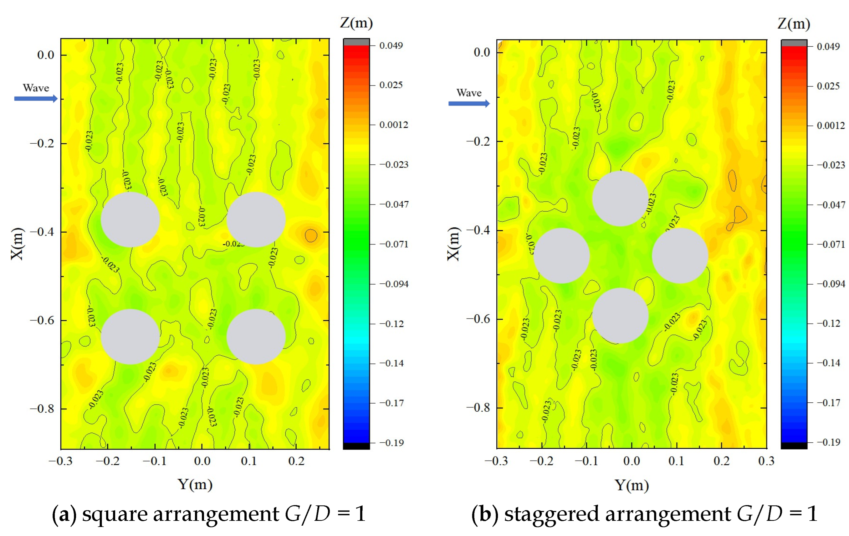
3.4. Local Scour for Various Pile Group Arrangements
- 1.
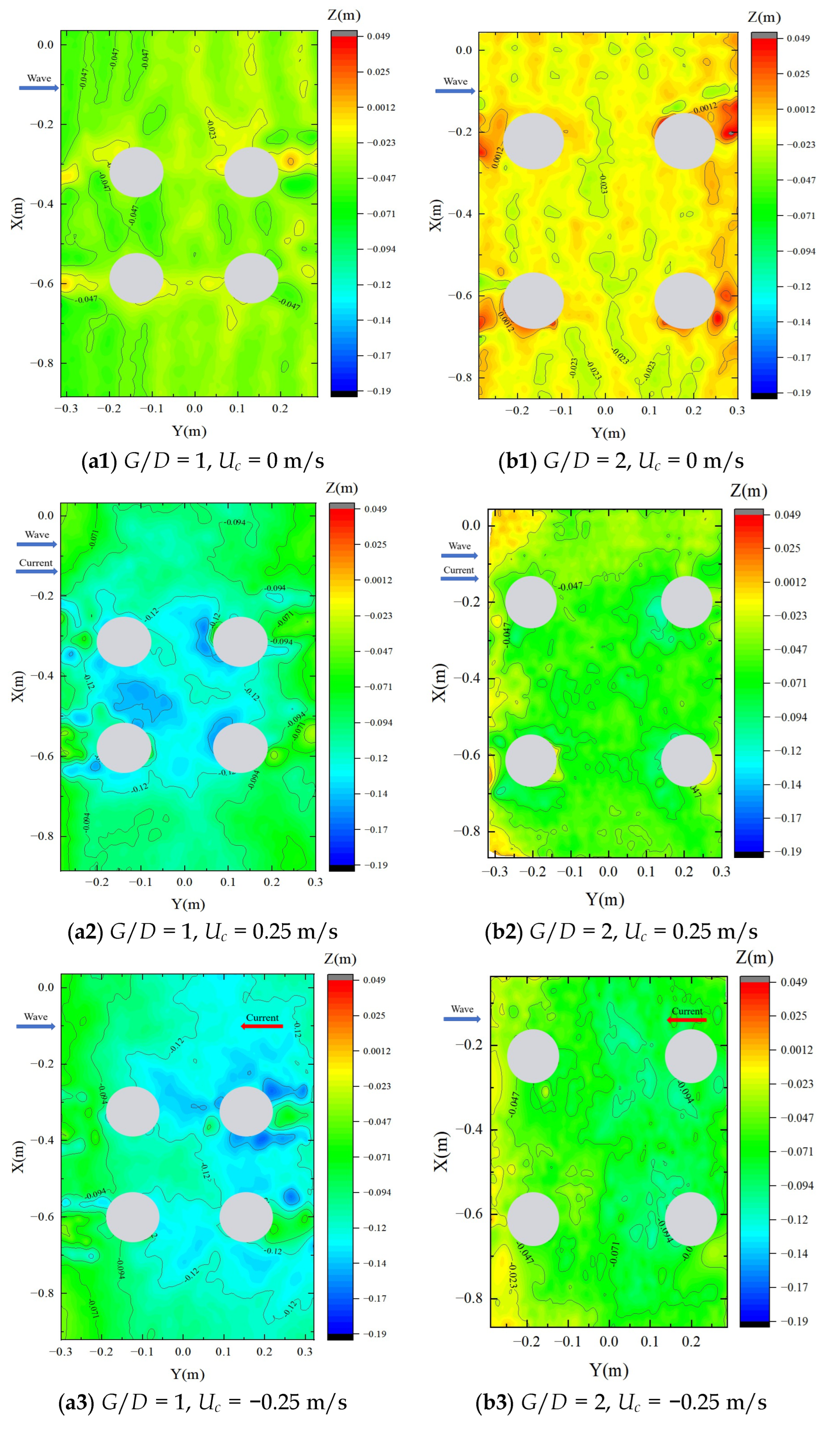
- Increasing the pile spacing can substantially reduce the maximum scour depth and prevent the formation of interconnected scour holes within the pile array, especially when the currents coexist with waves.
- 2.
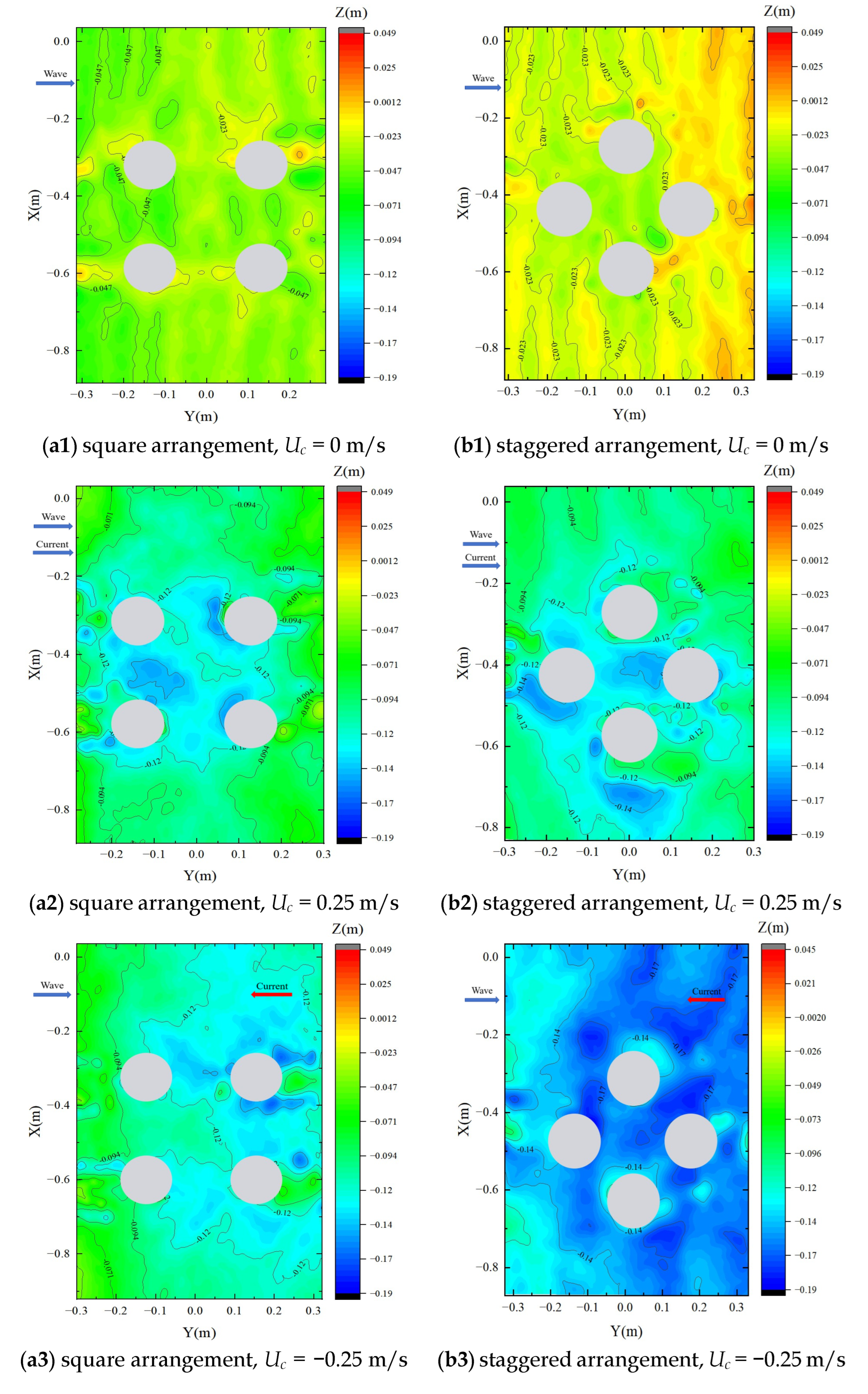
- Although staggered arrangements may improve structural efficiency or load distribution, they tend to have larger and deeper local scour, especially around downstream piles. For cases where downstream scour is critical, a square or more ordered arrangements my be preferable to limit local scour.
- 3.
- The direction of current is the dominant factor that strongly influences the position of maximum scour. Scour protection measurements should be tailored to current direction: the protection should be concentrated on upstream piles for co-directional currents and downstream piles for opposing currents, rather than uniformly applied to the entire pile group.
3.5. Irregular Wave-Induced Pore-Water Pressure and Local Scour Around Pile Groups
4. Conclusions
- 1.
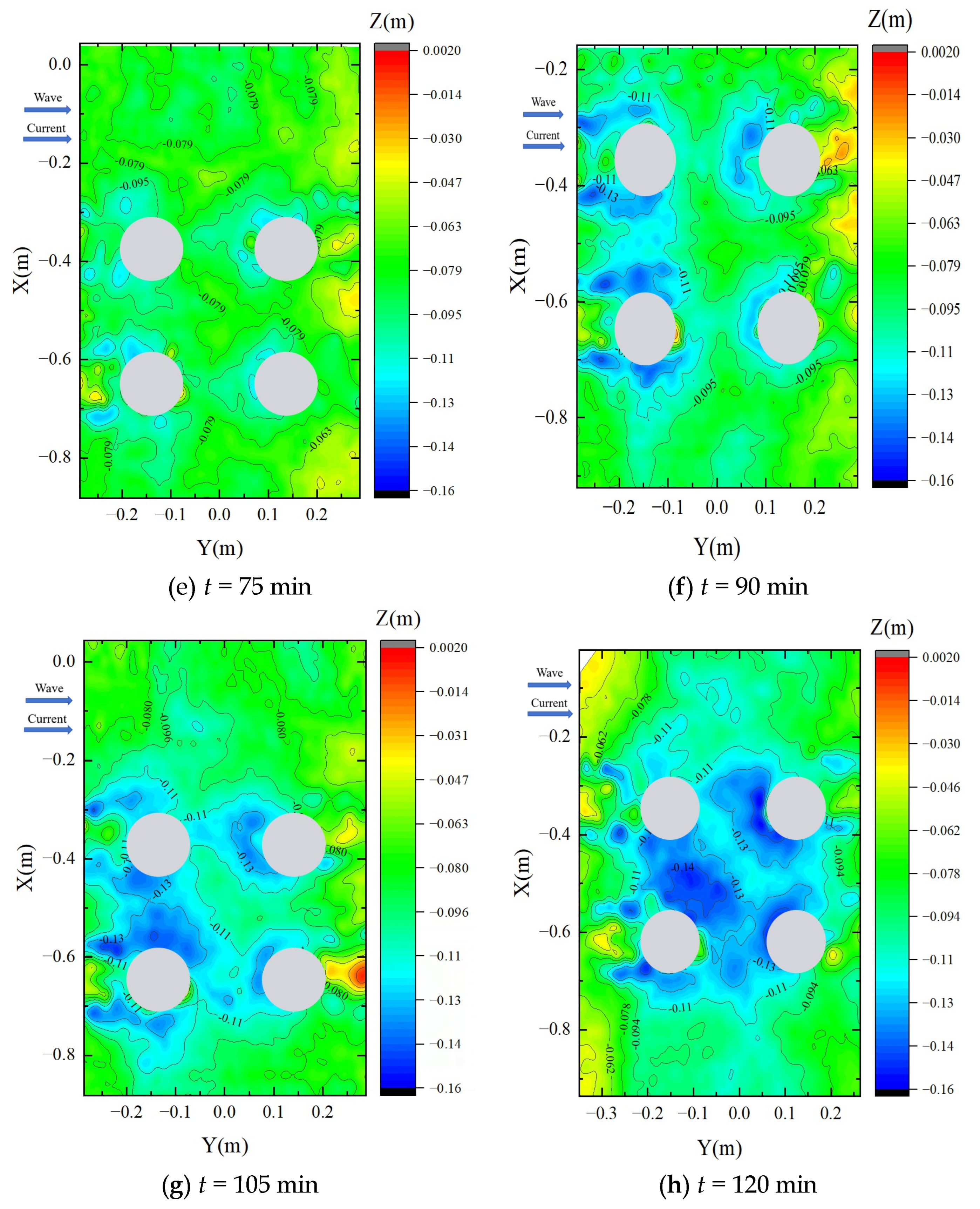
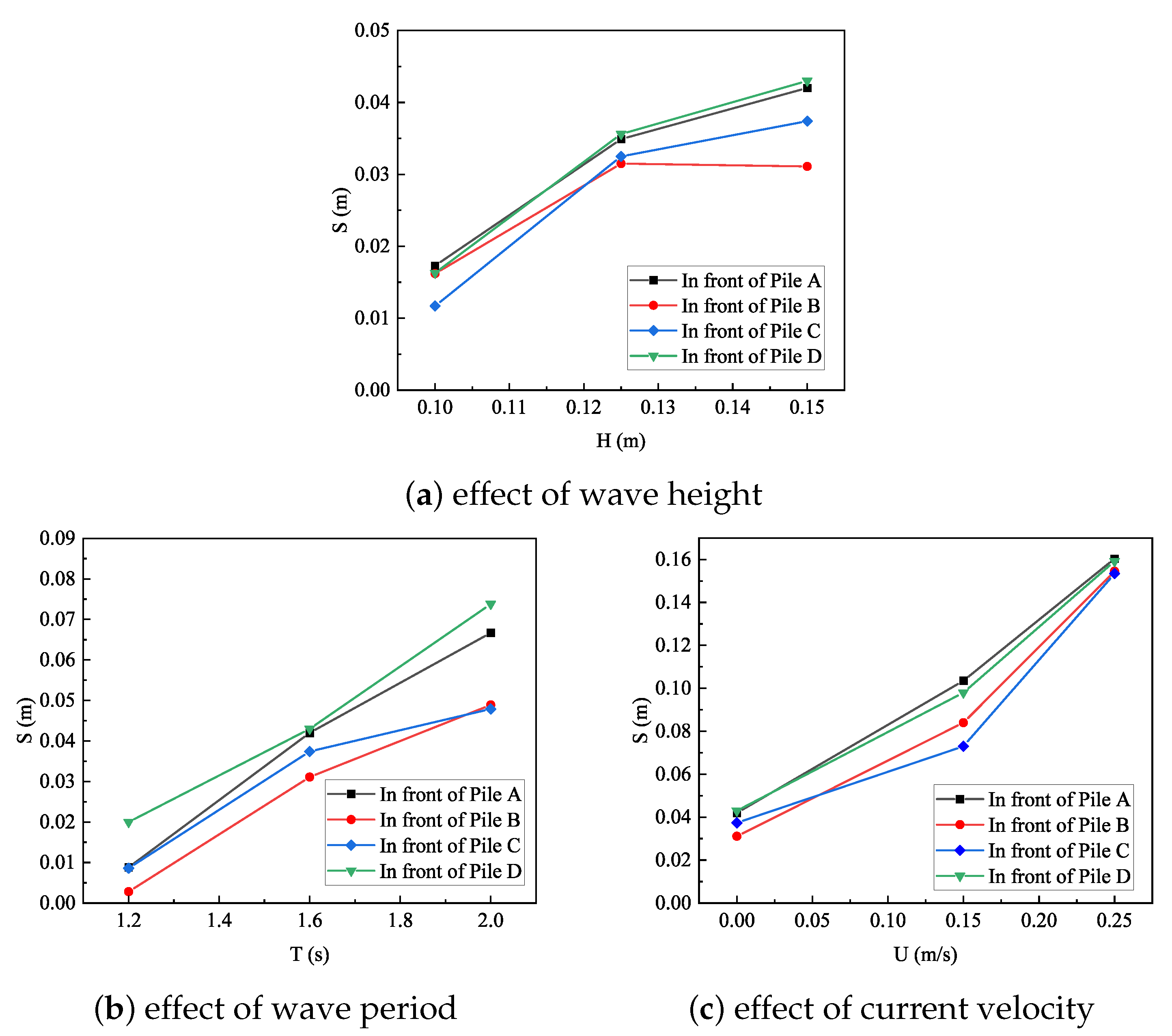
- The combined wave–current loading significantly intensifies the pressures of the pore-water and local scour compared to wave-only conditions. The presence of a steady current increases the maximum scour depth by approximately 3 to 5 times, with peak values reaching 0.16–0.19 m under combined wave–current loading compared to wave loading only. This is attributed to the fact that the presence of a steady current markedly enhances near-bed shear stress and vortex strength, leading to deeper and more spatially extensive local scour. Parametric analyses also demonstrate that the presence and magnitude of the current are the dominant factors in determining the maximum scour depth around pile groups, as both wave height and wave period can enhance the development of local scour depth.
- 2.
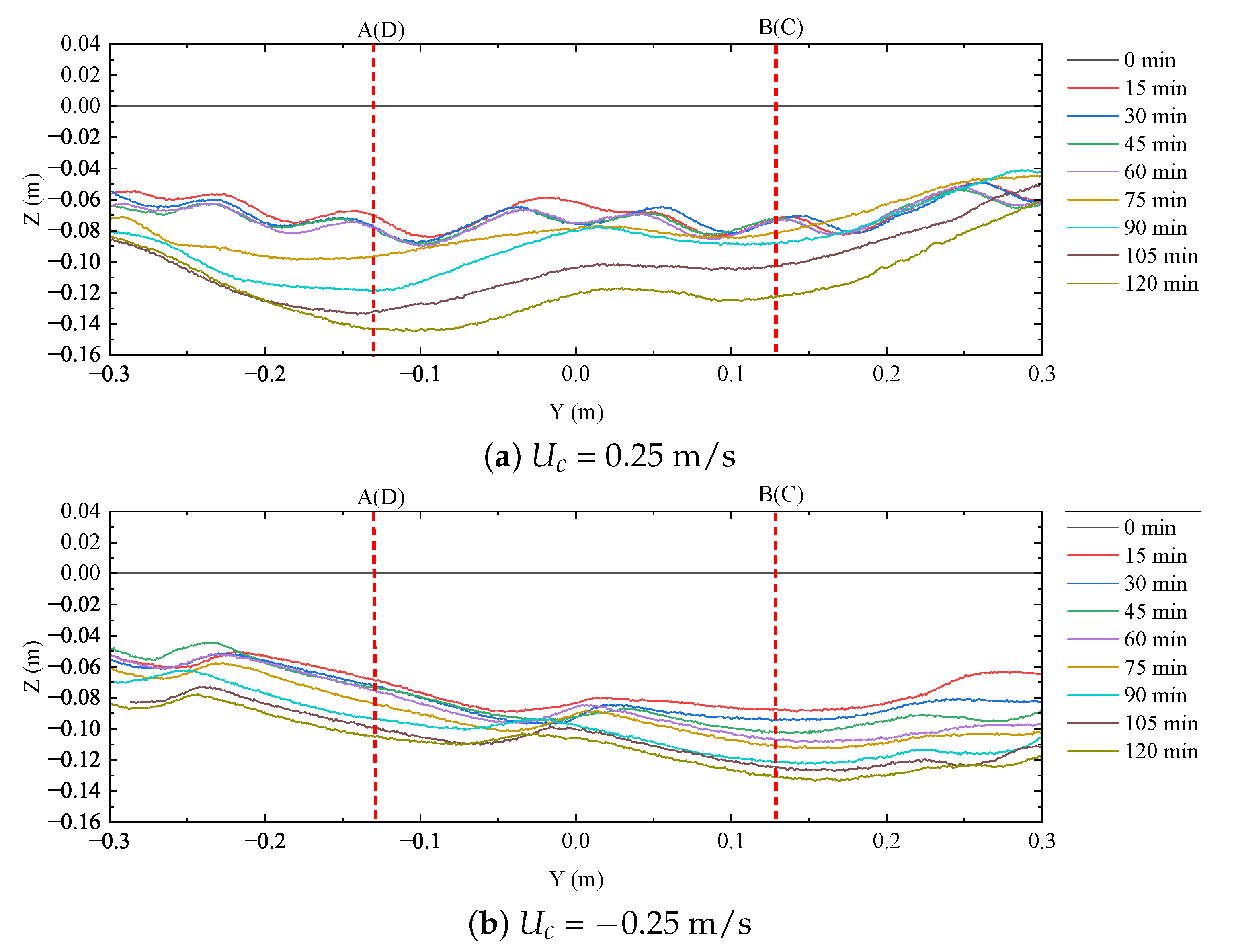
- The direction of the current relative to wave propagation governs the location and evolution rate of maximum scour around pile groups. Under wave–forward current conditions, the deepest scour develops primarily within the interior of the pile array, driven by flow contraction and gap-induced acceleration between piles. In contrast, under wave–opposing current conditions, the maximum scour shifts toward the downstream piles, and scour development proceeds more uniformly in time. These differences highlight the critical role of the current direction in pile group scour processes.
- 3.
- Pile spacing is the dominant geometric parameter controlling the scouring depth under combined wave–current loading. Small-spaced piles ( = 1) exhibit strong hydrodynamic interaction, resulting in an interconnected scour area and significantly larger maximum scour depths, while increasing pile spacing effectively weakens inter-pile interactions, reduces peak scour depth by approximately 30–40%, and confines scour to the vicinity of individual piles.
- 4.
- The arrangement of the pillars primarily influences the spatial distribution of scour rather than the maximum scour depth. Compared with a square arrangement, staggered pile configurations disrupt flow symmetry and enhance wake interaction, leading to downstream-shifted scour patterns. Although the staggered arrangement slightly increases the maximum scour depth, it mainly enlarges the affected area and alters the location of local scour zones.
- 5.
- Under irregular waves ( = 0.15 m, = 1.6 s, = 0 m/s), the maximum scour depth is consistently smaller than those of regular waves with equivalent height and period, while the affected area is more spatially diffuse.
Author Contributions
Funding
Data Availability Statement
Acknowledgments
Conflicts of Interest
References
- Chambel, J.; Fazeres-Ferradosa, T.; Miranda, F.; Bento, A.; Taveira-Pinto, F.; Lomonaco, P. A comprehensive review on scour and scour protections for complex bottom-fixed offshore and marine renewable energy foundations. Ocean Eng. 2024, 304, 117829. [Google Scholar] [CrossRef] [Scilit]
- Sumer, B.M.; Fredsøe, J. The Mechanics of Scour in the Marine Environment; World Scientific: Singapore, 2002. [Google Scholar] [CrossRef] [Scilit]
- Diaz, E.E.M.; Moreno, F.N.; Mohammadi, J. Investigation of common causes of bridge collapse in Colombia. Pract. Period. Struct. Des. Constr. 2009, 14, 194–200. [Google Scholar]
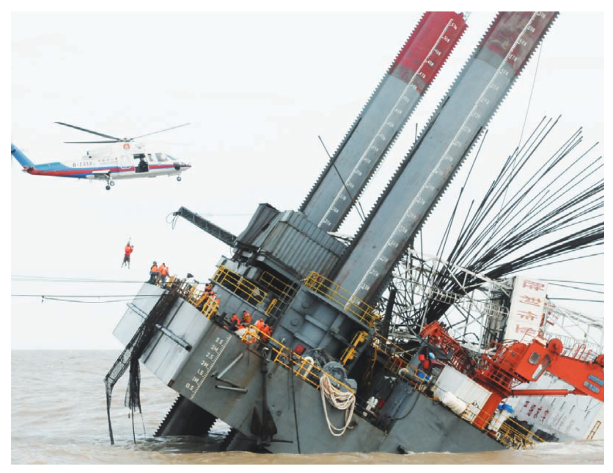
- Zhao, G. Analysis of the “9·7” Tilting Accident of Shengli Operation No. 3 Platform [in Chinese]. Mod. Occup. Saf. 2011, 7, 100–102. [Google Scholar]
- Wang, S.; Wang, P.; Zhai, H.; Zhang, Q.; Chen, L.; Duan, L.; Liu, Y.; Jeng, D.S. Experimental study for wave-induced pore-water pressures in a porous seabed around a mono-pile. J. Mar. Sci. Eng. 2019, 7, 237. [Google Scholar] [CrossRef] [Scilit]
- Yang, L.J.; Qi, W.G.; Li, Y.; Gao, F.P. Wave-current coupling effects on the variation modes of pore pressure response in a sandy seabed: Physical modeling and explicit approximations. J. Geophys. Res. Ocean. 2023, 128, e2022JC019158. [Google Scholar] [CrossRef] [Scilit]
- Zhang, Q.; Zhai, H.; Wang, P.; Wang, S.; Duan, L.; Chen, L.; Liu, Y.; Jeng, D.S. Experimental study on irregular wave-induced pore-water pressures in a porous seabed around a mono-pile. Appl. Ocean Res. 2020, 95, 102041. [Google Scholar] [CrossRef] [Scilit]
- Yu, J.H.; Gao, F.P.; Li, C.F. Response spectra for transient pore-pressure in a sandy seabed under random waves: Frequency-filtering effect. Ocean Eng. 2023, 279, 114490. [Google Scholar]
- Wang, M.Q.; Si, W.Q.; Go, Y.; Cui, L.; Jeng, D.S.; Sun, K.; Chen, B.; Zhao, H.Y. Experimental study of the random wave-induced hydrodynamic characteristic and soil response in a porous seabed around double piles. J. Mar. Sci. Eng. 2024, 12, 1715. [Google Scholar] [CrossRef] [Scilit]
- Qu, L.; An, H.; Draper, S.; Watson, P.; Zhao, M.; Harris, J.; Whitehouse, R.; Zhang, D. A review of scour impacting monopiles for offshore wind. Ocean Eng. 2024, 301, 117385. [Google Scholar] [CrossRef] [Scilit]
- Dey, S. Time-variation of scour in the vicinity of circular piers. Proc. Inst. Civ. Eng.-Water Marit. Energy 1999, 136, 67–75. [Google Scholar]
- Mia, M.F.; Nago, H. Design method of time-dependent local scour at circular bridge pier. J. Hydraul. Eng. ASCE 2003, 129, 420–427. [Google Scholar]
- Hong, J.H.; Goyal, M.K.; Chiew, Y.M.; Chua, L.H. Predicting time-dependent pier scour depth with support vector regression. J. Hydrol. 2012, 468, 241–248. [Google Scholar] [CrossRef] [Scilit]
- Zhai, H.L. Impact of seepage on local scour around bridge foundation in sandy seabed. Ph.D. Thesis, Southwest Jiao Tong University, Chengdu, China, 2023. (In Chinese) [Google Scholar]
- Zhai, H.L.; Jeng, D.-S. Integrated wave-seabed-scour model for local scour around a pipeline: PORO–FSSI–SCOUR–FOAM. Coast. Eng. 2024, 187, 104424. [Google Scholar] [CrossRef] [Scilit]
- Sumer, B.M.; Fredsøe, J.; Christensen, N. Scour around a vertical pile in waves. J. Waterw. Port Coast. Ocean. Eng. ASCE 1992, 118, 15–31. [Google Scholar] [CrossRef] [Scilit]
- Kobayashi, T.; Oda, K. Experimental study on developing process of local scour around a vertical cylinder. In Coastal Engineering 1994; ASCE Library: Reston, VA, USA, 1995; pp. 1284–1297. [Google Scholar]
- Keulegan, G.H.; Carpenter, L.H. Forces on cylinders and plates in an oscillating fluid. J. Res. Natl. Bur. Stand. 1958, 60, 423–440. [Google Scholar] [CrossRef] [Scilit]
- Lin, Z.; Dubravka, P.; Guo, Y.; Liao, C.; Tang, T. Near-trapping effect of wave-cylinders interaction on pore water pressure and liquefaction around a cylinder array. Ocean Eng. 2020, 218, 108947. [Google Scholar] [CrossRef] [Scilit]
- Wei, S.; Liang, Z.; Cui, L.; Zhai, H.; Jeng, D.S. Numerical study of seabed response and liquefaction around the jacket support offshore wind turbine foundation under the combined wave and current loading. Water Sci. Eng. 2022, 15, 78–88. [Google Scholar] [CrossRef] [Scilit]
- Liang, F.; Wang, C.; Huang, M.; Wang, Y. Experimental observations and evaluations of formulae for local scour at pile groups in steady currents. Mar. Georesour. Geotechnol. 2017, 35, 245–255. [Google Scholar]
- Ji, C.; Zhang, J.-f.; Zhang, Q.-h.; Li, M.-x.; Chen, T.-q. Experimental investigation of local scour around a new pile-group foundation for offshore wind turbines in bi-directional current. China Ocean Eng. 2018, 32, 737–745. [Google Scholar]
- Qi, W.G.; Li, Y.X.; Xu, K.; Gao, F.P. Physical modelling of local scour at twin piles under combined waves and current. Coast. Eng. 2019, 143, 63–75. [Google Scholar] [CrossRef] [Scilit]
- Corvaro, S.; Marini, F.; Mancinelli, A.; Lorenzoni, C.; Brocchini, M. Hydro-and morpho-dynamics induced by a vertical slender pile under regular and random waves. J. Waterw. Port Coast. Ocean. Eng. ASCE 2018, 144, 04018018. [Google Scholar] [CrossRef] [Scilit]
- Sumer, B.M.; Fredsøe, J. Scour around pile in combined waves and current. J. Hydraul. Eng. ASCE 2001, 127, 403–411. [Google Scholar]
- Zhao, H.; Lin, F.; Gao, Y.; Wang, Z.; Li, M.; Liu, X.; Han, S.; Jeng, D.S. Effect of clay content on the coupled seabed response and local scour around a free-spanning pipeline under combined waves and currents. Coast. Eng. 2025, 204, 104910. [Google Scholar] [CrossRef] [Scilit]
- Sumer, B.M.; Fredsøe, J. Wave scour around group of vertical piles. J. Waterw. Port Coast. Ocean. Eng. ASCE 1998, 124, 248–256. [Google Scholar]
- Amini, A.; Melville, B.W.; Ali, T.M.; Ghazali, A.H. Clear-water local scour around pile groups in shallow-water flow. J. Hydraul. Eng. ASCE 2012, 138, 177–185. [Google Scholar]
- Bayram, A.; Larson, M. Analysis of scour around a group of vertical piles in the field. J. Waterw. Port Coast. Ocean. Eng. ASCE 2000, 126, 215–220. [Google Scholar]
- Qi, W.G.; Gao, F.P. Physical modeling of local scour development around a large-diameter monopile in combined waves and current. Coast. Eng. 2014, 83, 72–81. [Google Scholar] [CrossRef] [Scilit]
- Wang, H.; Tang, H.; Liu, Q.; Wang, Y. Local scouring around twin bridge piers in open-channel flows. J. Hydraul. Eng. ASCE 2016, 142, 06016008. [Google Scholar]
- Zen, K.; Yamazaki, H. Mechanism of wave-induced liquefaction and densification in seabed. Soils Found. 1990, 30, 90–104. [Google Scholar] [CrossRef] [Scilit]
- Hughes, S.A. Physical Models and Laboratory Techniques in Coastal Engineering; World Scientific: Singapore, 1993. [Google Scholar]
- Palemón-Arcos, L.; Torres-Freyermuth, A.; Pedrozo-Acuña, A.; Salles, P. On the role of uncertainty for the study of wave–structure interaction. Coast. Eng. 2015, 106, 32–41. [Google Scholar] [CrossRef] [Scilit]
- Scaravaglione, G.; Melby, J.A. A comprehensive review of the primary sources of uncertainty in stone armor stability. Coast. Eng. 2026, 205, 104930. [Google Scholar] [CrossRef] [Scilit]
- Dean, R.; Dalrymple, R.A. Water Wave Mechanics for Engineers and Scientists; World Scientific: Singapore, 1984. [Google Scholar]
- Hsu, H.C.; Chen, Y.Y.; Hsu, J.R.C.; Tseng, W.J. Nonlinear water waves on uniform current in Lagrangian coordinates. J. Nonlinear Math. Phys. 2009, 16, 47–61. [Google Scholar] [CrossRef] [Scilit]
- Shields, A. Application of Similitude Mechanics and Research on Turbulence to Bed Load Movement; California Institute of Technology: Pasadena, CA, USA, 1937. [Google Scholar]
- Chien, N.; Wan, Z. Mechanics of Sediment Transport; ASCE: Reston, VA, USA, 1976. [Google Scholar]
- Soulsby, R. Dynamics of Marine Sands; Thomas Telford: London, UK, 1997. [Google Scholar]
- Soulsby, R.L.; Whitehouse, R.J.S. Threshold of sediment motion in coastal environments. In Proceedings of the Pacific Coasts and Ports’97. Proceedings; Centre for Advanced Engineering, University of Canterbury: Christchurch, New Zealand, 1997; Volume 1, pp. 149–154. [Google Scholar]
- Zhao, K.F.; Wang, Y.F.; Liu, P.L.-F. A guide for selecting periodic water wave theories-Le Méhauteé’s graph revisited. Coast. Eng. 2024, 188, 104432. [Google Scholar] [CrossRef] [Scilit]
- Goda, Y. Random Seas and Design of Marine Structures; World Scientific Press: Singapore, 2000. [Google Scholar]







| Reference | Main Content | Comparison |
|---|---|---|
| Sumer et al. [16] | regular wave, mono-pile | no irregular wave, no wave–current, no pore-water pressure, no pile group foundation |
| Kobayashi and Oda [17] | regular wave, mono-pile | no irregular wave, no wave–current, no pore-water pressure, no pile group foundation |
| Liang et al. [21] | steady current, mono-pile, pile group foundation | no wave–current, no pore-water pressure |
| Ji et al. [22] | bidirectional current, pile group foundation | no wave–current, no pore-water pressure |
| Qi et al. [23] | wave–current, twin piles | no irregular wave, no pore-water pressure, no pile group foundation |
| Corvaro et al. [24] | wave–current, mono-pile | no irregular wave, no pore-water pressure, no pile group foundation |
| Sumer and Fredsøe [25] | wave–current, mono-pile | no pore-water pressure, no pile group foundation |
| Sumer and Fredsøe [27] | wave–current, mono-pile | no pore-water pressure, no pile group foundation |
| Amini et al. [28] | wave–current, pile group foundation | no irregular wave, no pore-water pressure |
| Bayram and Larson [29] | wave–current, pile group foundation | no irregular wave, no pore-water pressure |
| This study | regular and irregular wave, wave–current, pore-water pressure, pile groups |
| Soil Properties | Soil Value | Unit |
|---|---|---|
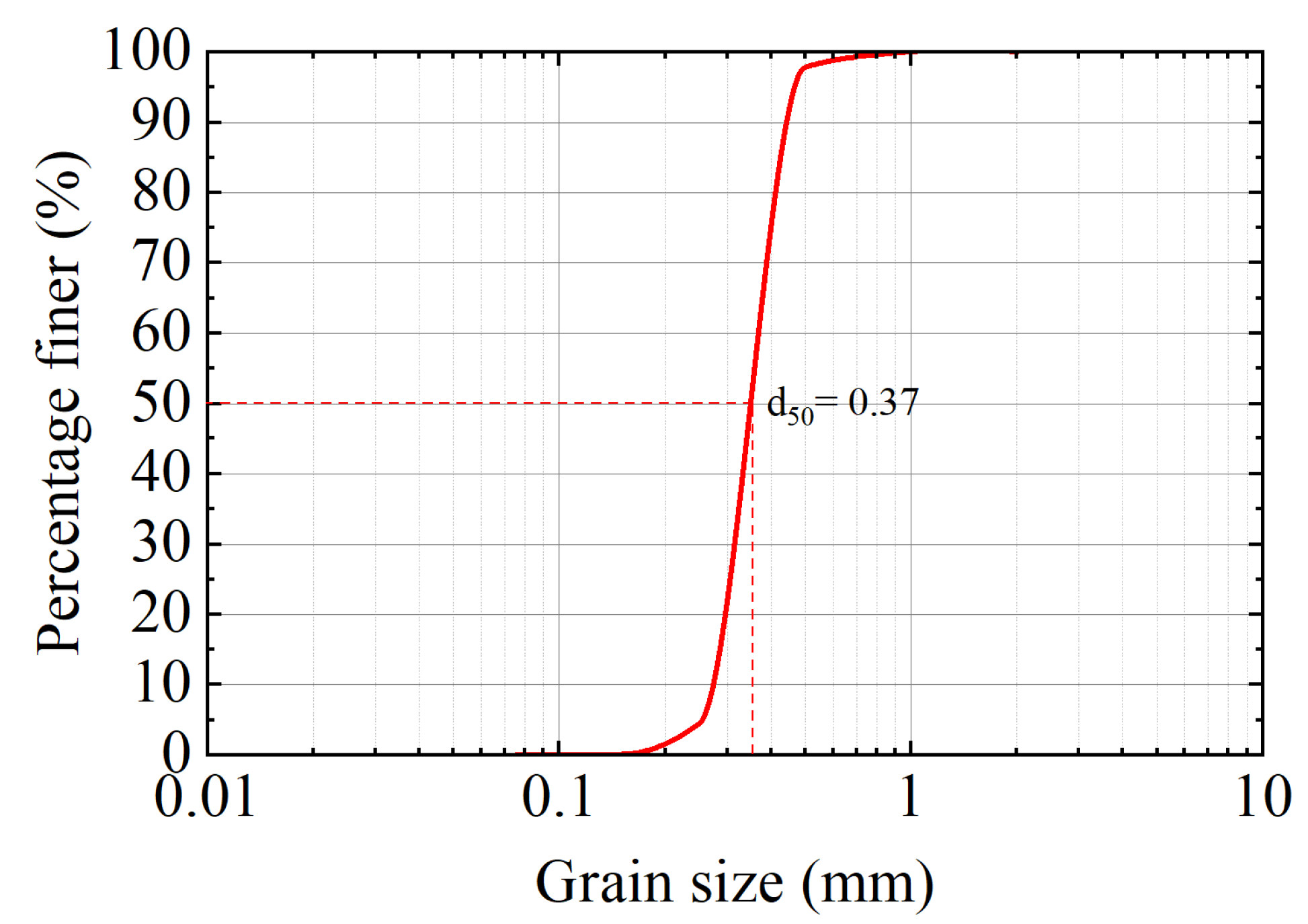
| Median grain size () | 0.37 | mm |
| Coefficient of uniformity () | 1.52 | - |
| Curvature coefficient () | 0.96 | - |
| Dry density () | 1.50 | g/cm3 |
| Maximum dry density () | 1.58 | g/cm3 |
| Minimum dry density () | 1.25 | g/cm3 |
| Specific gravity (s) | 2.65 | - |
| Void ratio (e) | 0.77 | - |
| Porosity (n) | 0.43 | - |
| Permeability coefficient () | 0.30 | cm/s |
| Poisson’s ratio () | 0.30 | - |
| Shear modulus (G) | 12.69 | MN/m2 |
| Relative density () | 0.81 | - |
| Group No. | H (m) | T (s) | (m/s) | (m/s) | KC | Re | ||
|---|---|---|---|---|---|---|---|---|
| 1 | 0.1 | 1.6 | 0.0338 | 0 | 0.1854 | 2.20 | 0.1148 | 25,027.87 |
| 2 | 0.125 | 1.6 | 0.0422 | 0 | 0.2342 | 2.78 | 0.1831 | 31,611.96 |
| 3 | 0.15 | 1.6 | 0.0506 | 0 | 0.2839 | 3.36 | 0.2692 | 38,326.90 |
| 4 | 0.15 | 1.2 | 0.075 | 0 | 0.2071 | 1.84 | 0.1432 | 27,956.38 |
| 5 | 0.15 | 2 | 0.0387 | 0 | 0.3303 | 4.89 | 0.3642 | 44,585.14 |
| 6 | 0.15 | 1.6 | 0.0506 | 0.15 | 0.3762 | 4.46 | 0.2897 | 38,326.90 |
| 7 | 0.15 | 1.6 | 0.0506 | 0.25 | 0.4377 | 5.19 | 0.3263 | 38,326.90 |
| 8 | 0.15 | 1.6 | 0.0506 | −0.25 | 0.1301 | 1.54 | 0.3263 | 38,326.90 |
| 9 * | 0.15 | 1.6 | 0.0506 | 0 | 0.2839 | 3.36 | 0.2692 | 38,326.90 |
Disclaimer/Publisher’s Note: The statements, opinions and data contained in all publications are solely those of the individual author(s) and contributor(s) and not of MDPI and/or the editor(s). MDPI and/or the editor(s) disclaim responsibility for any injury to people or property resulting from any ideas, methods, instructions or products referred to in the content. |
© 2026 by the authors. Licensee MDPI, Basel, Switzerland. This article is an open access article distributed under the terms and conditions of the Creative Commons Attribution (CC BY) license.
Share and Cite
Wang, Z.; Cui, L.; Liang, Z.; Li, M.; Liu, D.; Chang, D.; Sun, K.; Jeng, D.-S. Physical Modeling of Hydrodynamics, Pore-Water Pressures, and Local Scour in a Sandy Seabed Around Pile Groups Under Regular Wave–Current and Irregular Wave Loading. Sustainability 2026, 18, 2252. https://doi.org/10.3390/su18052252
Wang Z, Cui L, Liang Z, Li M, Liu D, Chang D, Sun K, Jeng D-S. Physical Modeling of Hydrodynamics, Pore-Water Pressures, and Local Scour in a Sandy Seabed Around Pile Groups Under Regular Wave–Current and Irregular Wave Loading. Sustainability. 2026; 18(5):2252. https://doi.org/10.3390/su18052252
Chicago/Turabian StyleWang, Zheng, Lin Cui, Zuodong Liang, Mengxiao Li, Dajun Liu, Dayu Chang, Ke Sun, and Dong-Sheng Jeng. 2026. "Physical Modeling of Hydrodynamics, Pore-Water Pressures, and Local Scour in a Sandy Seabed Around Pile Groups Under Regular Wave–Current and Irregular Wave Loading" Sustainability 18, no. 5: 2252. https://doi.org/10.3390/su18052252
APA StyleWang, Z., Cui, L., Liang, Z., Li, M., Liu, D., Chang, D., Sun, K., & Jeng, D.-S. (2026). Physical Modeling of Hydrodynamics, Pore-Water Pressures, and Local Scour in a Sandy Seabed Around Pile Groups Under Regular Wave–Current and Irregular Wave Loading. Sustainability, 18(5), 2252. https://doi.org/10.3390/su18052252