Plastic Damage Analysis and Structural Optimisation of Reinforced-Steel Fibre Concrete Lining for Underground Gas Storage Caverns

 ,
,
Abstract
1. Introduction
2. Numerical Model Establishment of R-SFC Lining
2.1. Geometry and Applicability of the 2D Plane Strain Model
2.1.1. Geometry and Basic Assumptions
- (1)
- The volume of the rock cavern remains constant;
- (2)
- The surrounding rock and steel reinforcement are isotropic materials;
- (3)
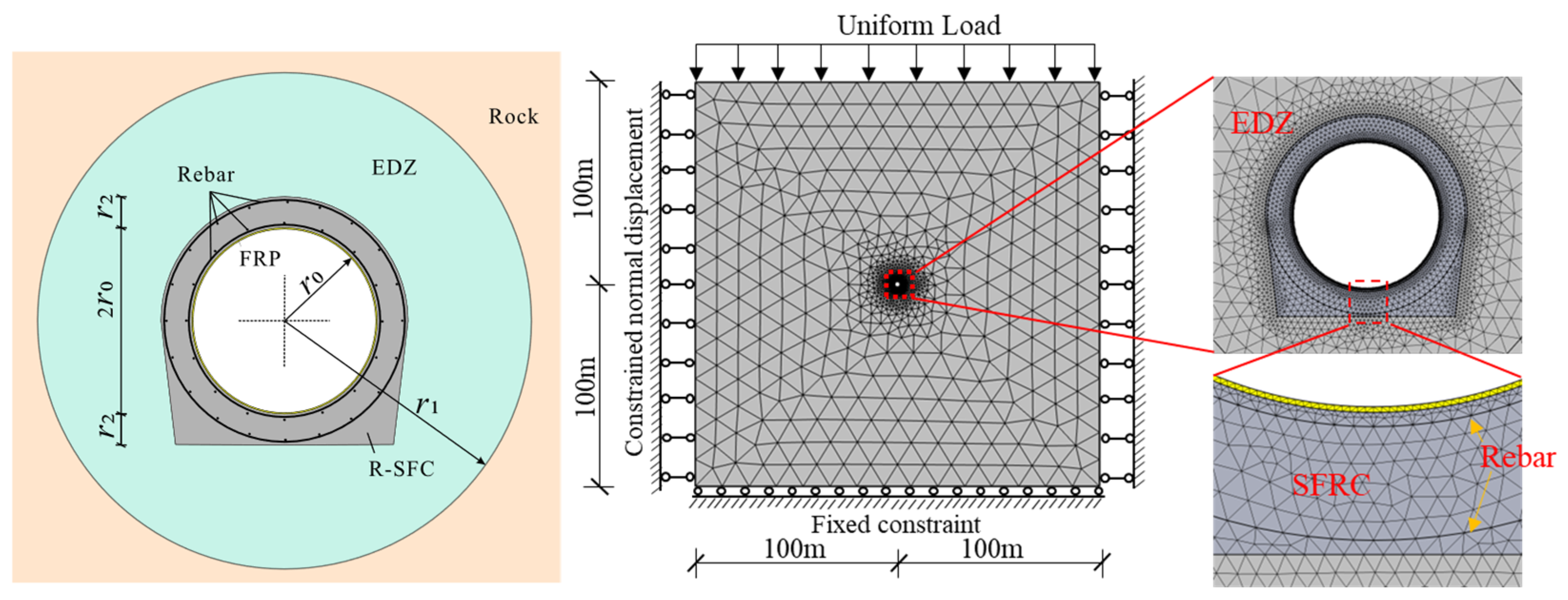
- Due to good contact between the surrounding rock and the lining layer, and between the lining layer and the FRP fibre sealing layer, the thermal resistance is zero;
- (4)
- Air leakage is neglected;
- (5)
- The bond slip between the rebar and SFRC is ignored;
- (6)
- The air inside the cavern is uniformly distributed, so the pressure and temperature on the cavern walls are uniform;
- (7)
- Other parameters are simplified based on the equivalent thickness criterion.
2.1.2. Applicable Conditions for the 2D Plane Strain Model
2.2. Thermodynamic Control Equation
2.3. Constitutive Model for Materials
2.3.1. FRP Sealing Layer and Steel Rebar
2.3.2. Concrete and SFRC Lining Layer
2.3.3. Rock Layer and EDZ
2.4. Building Numerical Models and Boundary Conditions
3. Numerical Simulation Results and Analysis
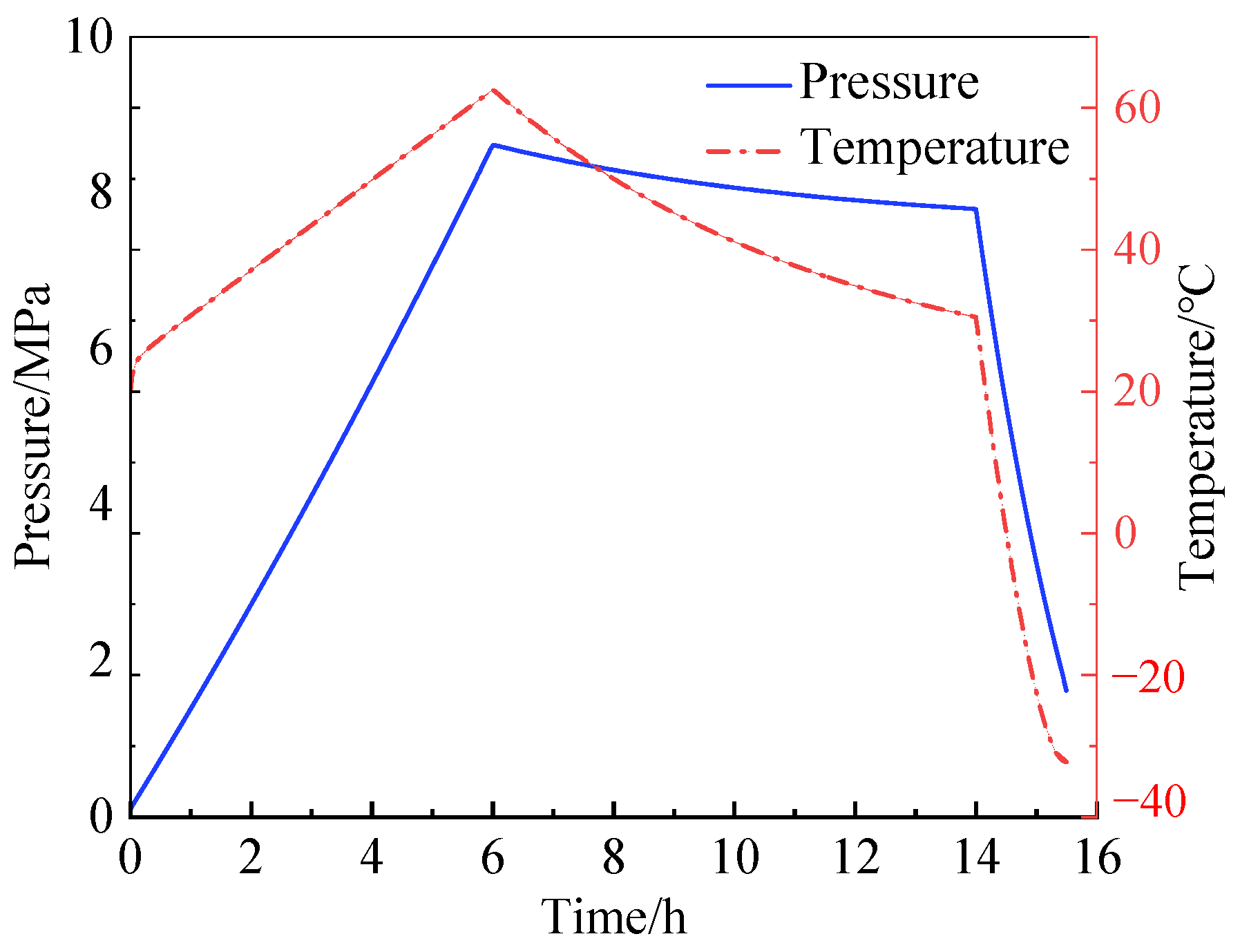
3.1. Temperature and Pressure in the Cavern
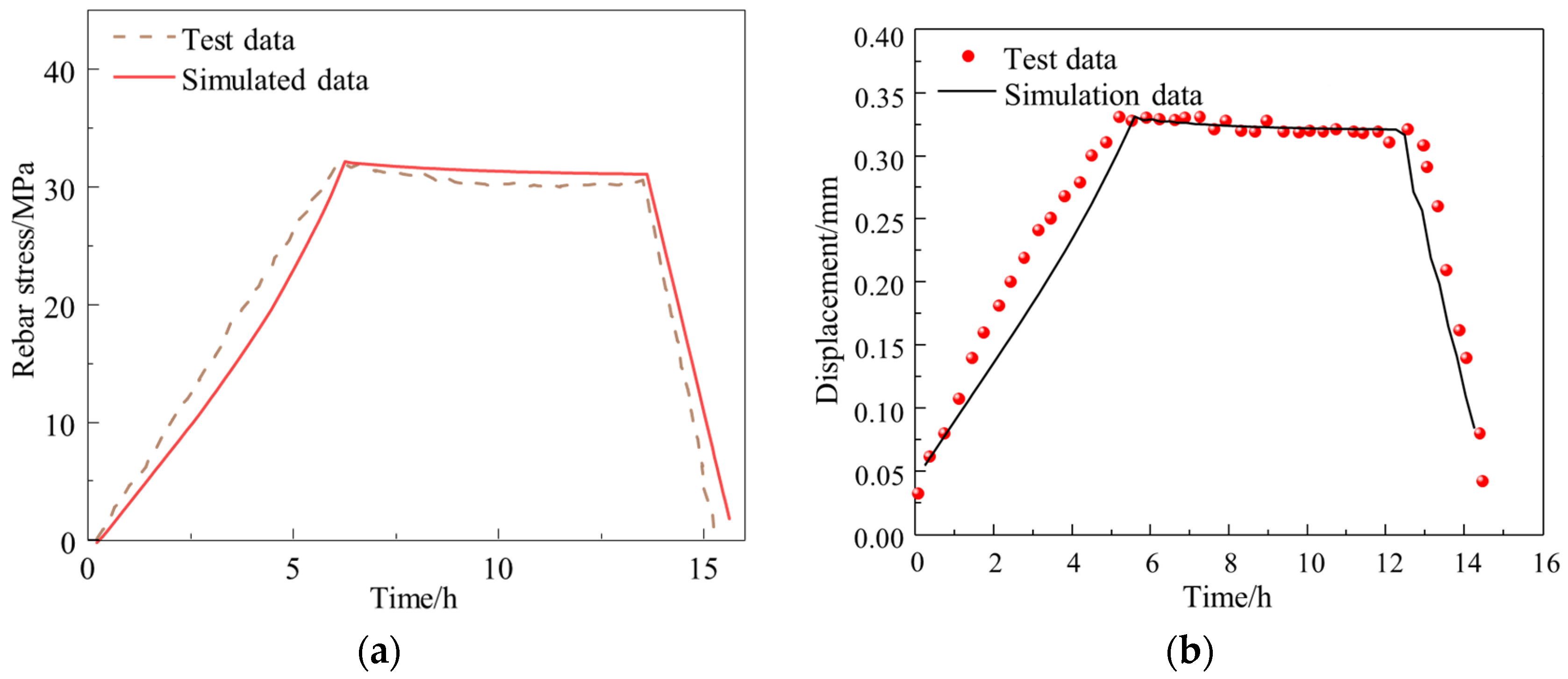
3.2. Model Validation
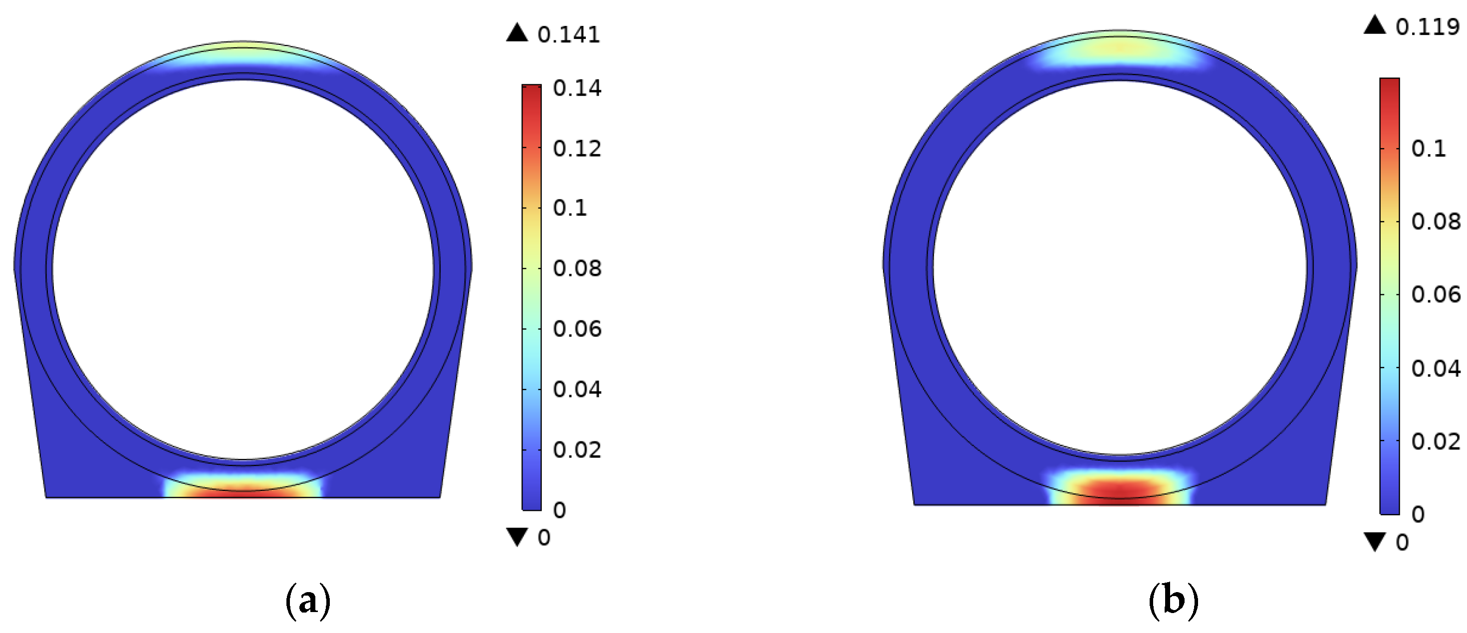
3.3. Performance Analysis of R-SFC Lining
3.4. Structural Parameters Influence Analysis on Plastic Damage of R-SFC Lining
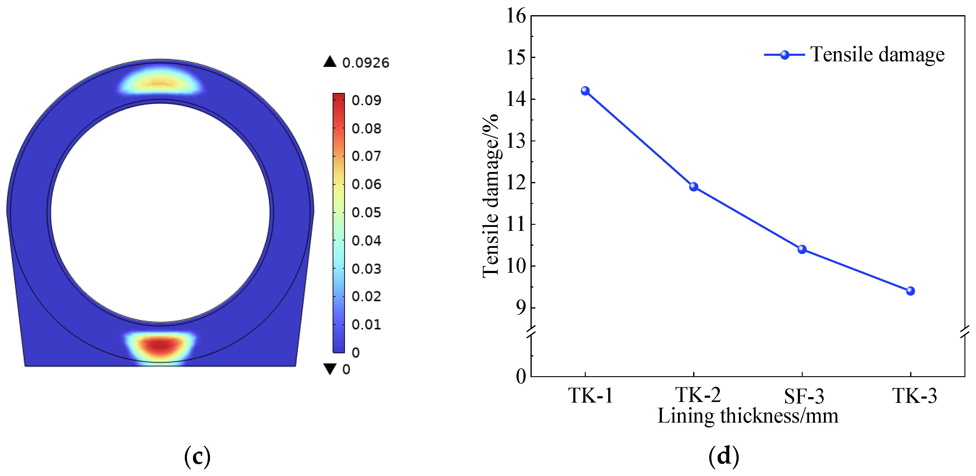
3.4.1. Lining Thickness
3.4.2. Cavern Diameter
3.4.3. Rebar Diameter
3.5. Lining–Rock Internal Pressure Sharing Under Parameter Variations
- (1)
- Function of steel fibre volume fraction: The tensile performance is significantly improved through the bridging effect of steel fibres. Within the volume fraction range of 0.5% to 1.5%, the internal pressure borne by the lining increases from 2.55 MPa to 2.58 MPa, which is a 6.2% to 7.5% improvement compared to plain concrete (2.4 MPa). It demonstrates that enhancing lining strength can bear more internal pressure and indirectly reduce the required surrounding rock strength.
- (2)
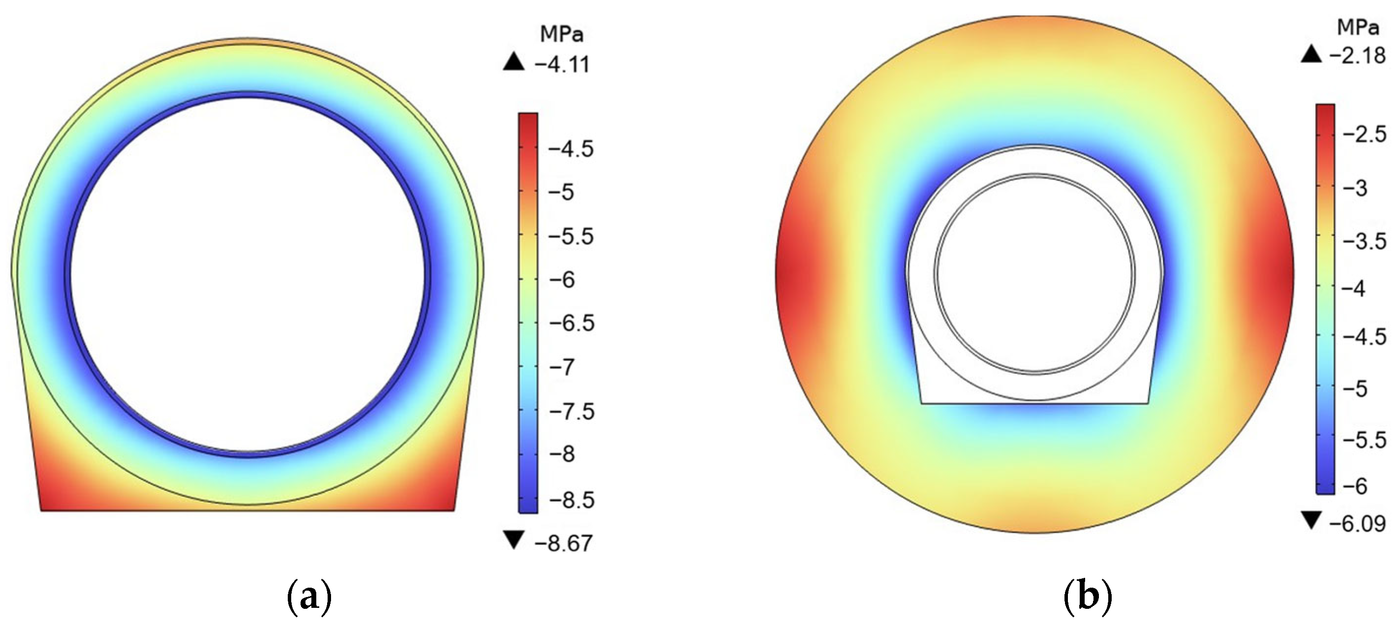
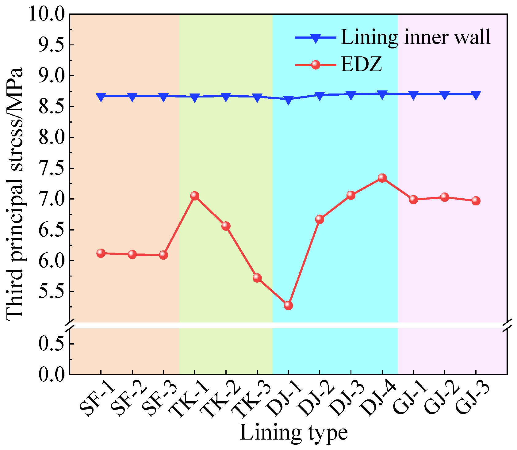
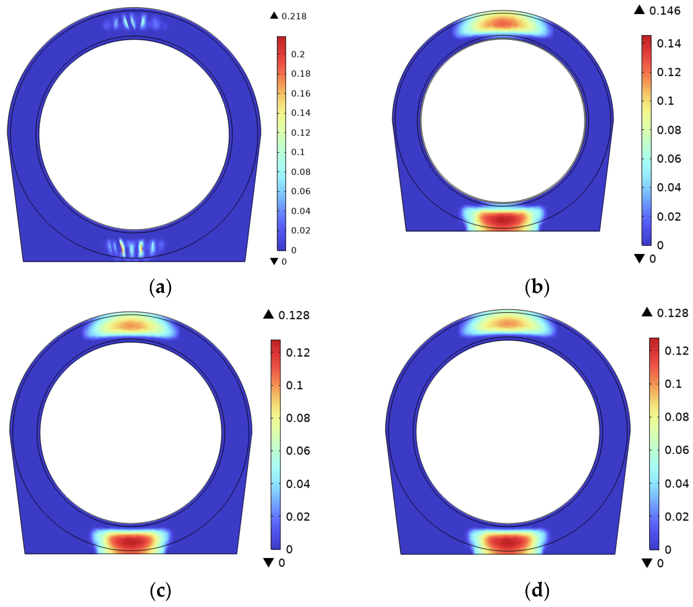
- Regulation of lining thickness: As the lining thickness increases from 300 mm to 600 mm in 100 mm increments, the maximum internal pressure on the EDZ inner wall decreases successively to 7.05 MPa, 6.56 MPa, 6.09 MPa, and 5.72 MPa, with reductions of 7%, 7.16%, and 6.08% between adjacent values. The increase in thickness enhances the section modulus and leads to stress redistribution, so that the lining itself carries a greater share of the internal pressure. The reduction in EDZ pressure becomes smaller beyond 500 mm, indicating that thicknesses in the 400 to 500 mm range provide a favourable balance between damage control and material economy.
- (3)
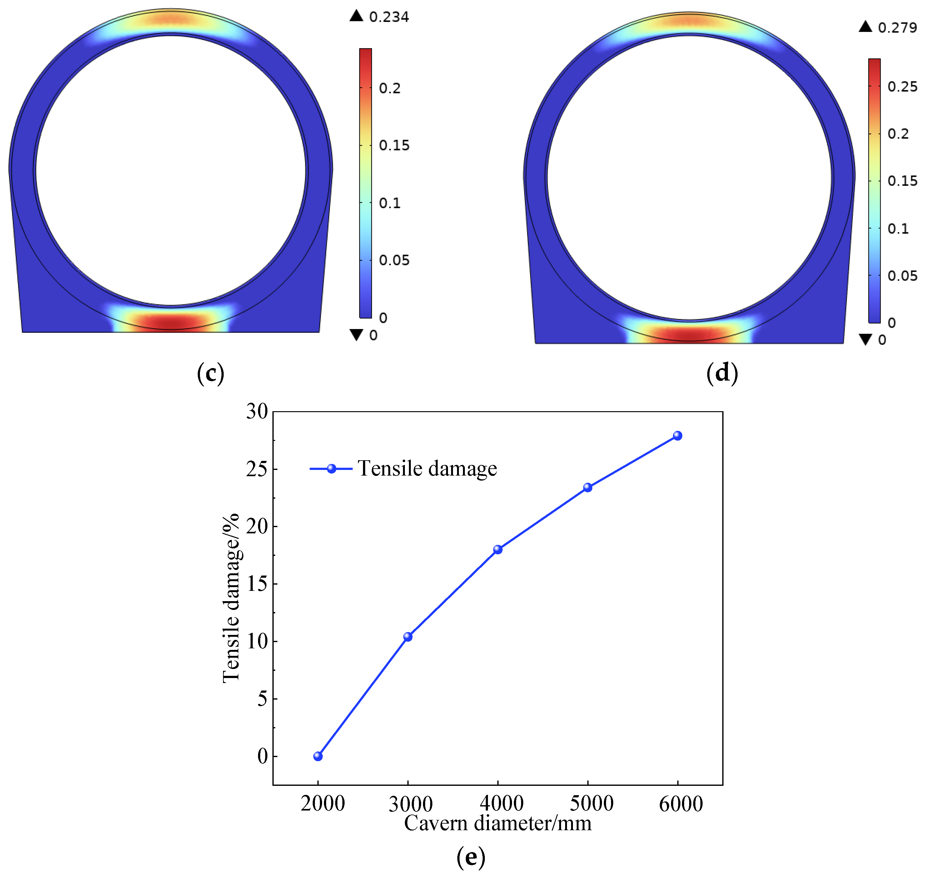
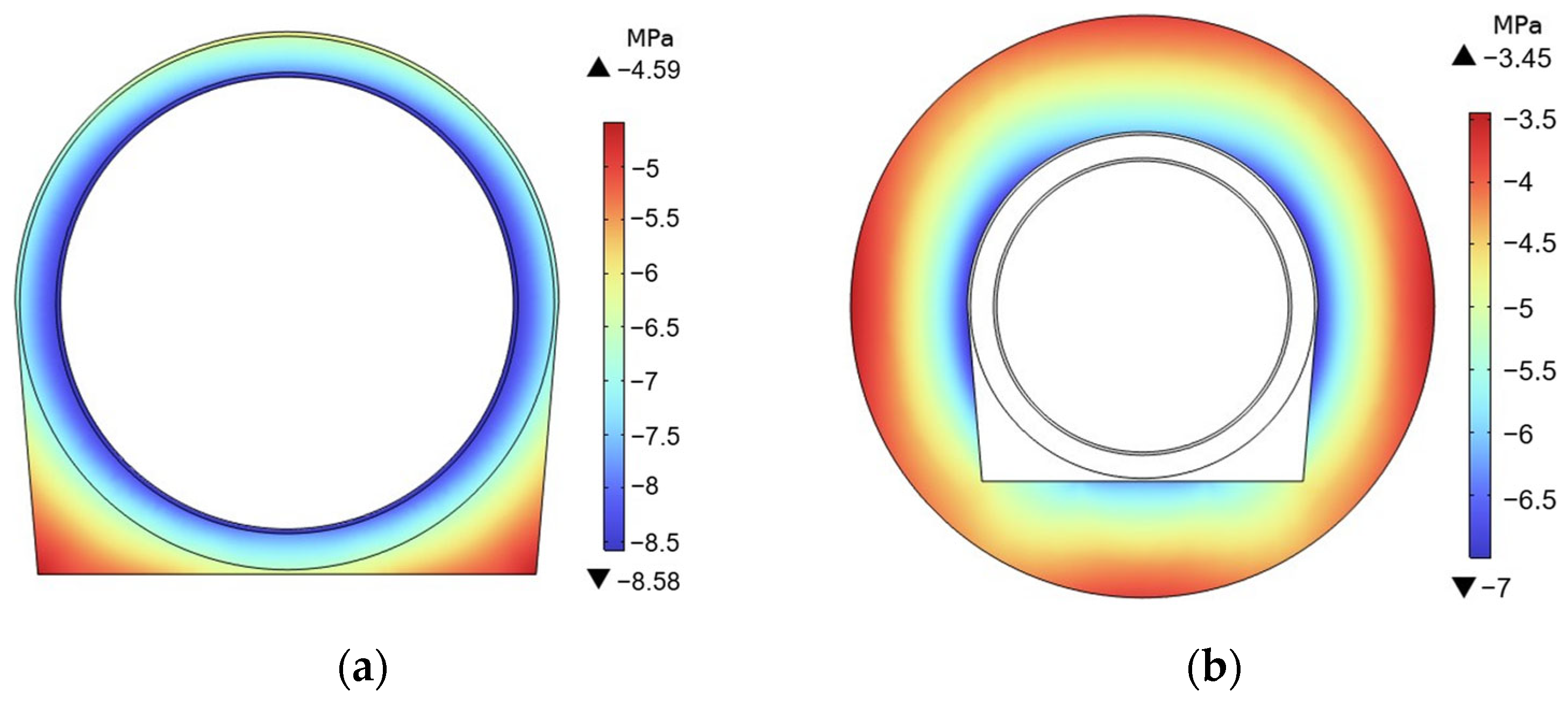
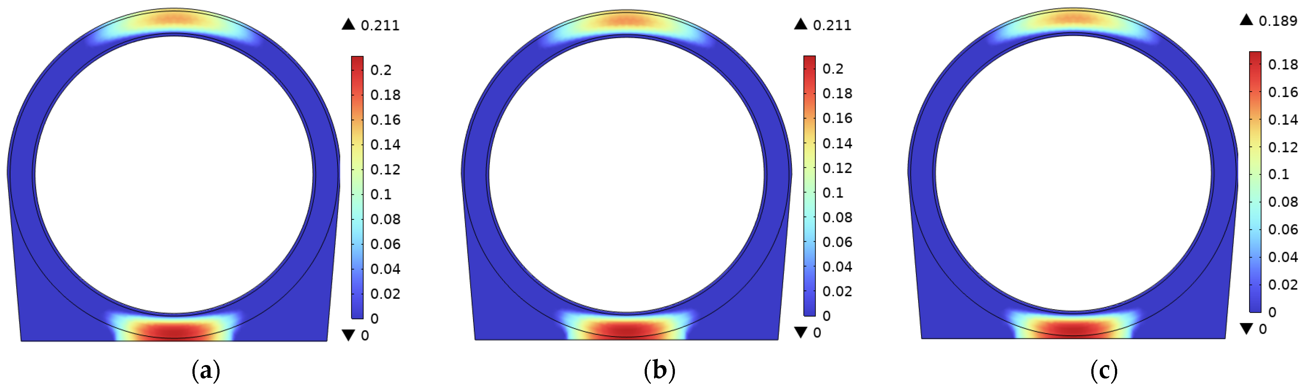
- Effect of cavern diameter: When the cavern diameter increases from 2000 mm to 6000 mm in 1000 mm increments, the maximum internal pressure on the EDZ inner wall rises successively to 5.27 MPa, 6.09 MPa, 6.67 MPa, 7.06 MPa, and 7.34 MPa, with increases of 15.6%, 9.5%, 5.8%, and 4.0%. As the cavern diameter increases at fixed lining thickness, the bending stiffness of the lining ring decreases, transferring more internal pressure to the surrounding rock, while the rate of pressure rise gradually slows. To avoid overloading the surrounding rock and ensure a reasonable storage volume, a cavern diameter of 2000–4000 mm is recommended.
- (4)
- Influence boundary of rebar: Adjustments to the diameter of circumferential rebar have less than a 3% impact on the distribution of radial compressive stress, verifying the mechanical division of labour where R-SFC matrix and surrounding rock primarily bear radial loads, while the steel fibres bear the principal hoop tensile stress and the rebars provide supplementary tensile capacity.
4. PSO-Based Lining Prediction and Multi-Objective Optimisation
4.1. Data Preparation
4.2. Construction and Results of the PSO-BP Prediction Model
4.2.1. PSO-BP Parameter Setting
4.2.2. Forecast Results
4.3. Optimisation of R-SFC Lining by MOPSO Algorithm
5. Conclusions and Future Work
- (1)
- The incorporation of steel fibres significantly enhances the tensile and cracking resistance of concrete linings, with increased fibre volume fraction improving the uniformity of tensile damage distribution. The proposed R-SFC lining is shown to provide a clear structural advantage over the conventional reinforced concrete lining, with simultaneous reductions in maximum tensile damage and steel consumption.
- (2)
- The R-SFC lining shares the internal pressure with the surrounding rock through complementary mechanical roles, in which the concrete lining and the surrounding rock jointly resist the radial compressive load, while the steel fibres bear the principal hoop tensile stress and the rebars provide supplementary hoop tensile capacity. Accordingly, the rebar diameter primarily contributes to hoop tensile reinforcement, with only a limited influence on the radial pressure distribution between the lining and the surrounding rock.
- (3)
- The thickness-to-diameter ratio is identified as the key geometric parameter governing structural response, with larger ratios reducing tensile damage in the lining and decreasing the pressure transmitted to the surrounding rock. Within the parameter range of this study (lining thickness of 300–600 mm, cavern diameter of 2000–6000 mm, steel fibre volume fraction of 0.5–1.5%, and double row steel bar diameter of 18–28 mm), a thickness-to-diameter ratio of 1/8 to 1/5 is recommended for the geometric design of R-SFC lining in horizontal cylindrical CAES caverns at large burial depth, balancing lining damage against surrounding rock loading.
- (4)
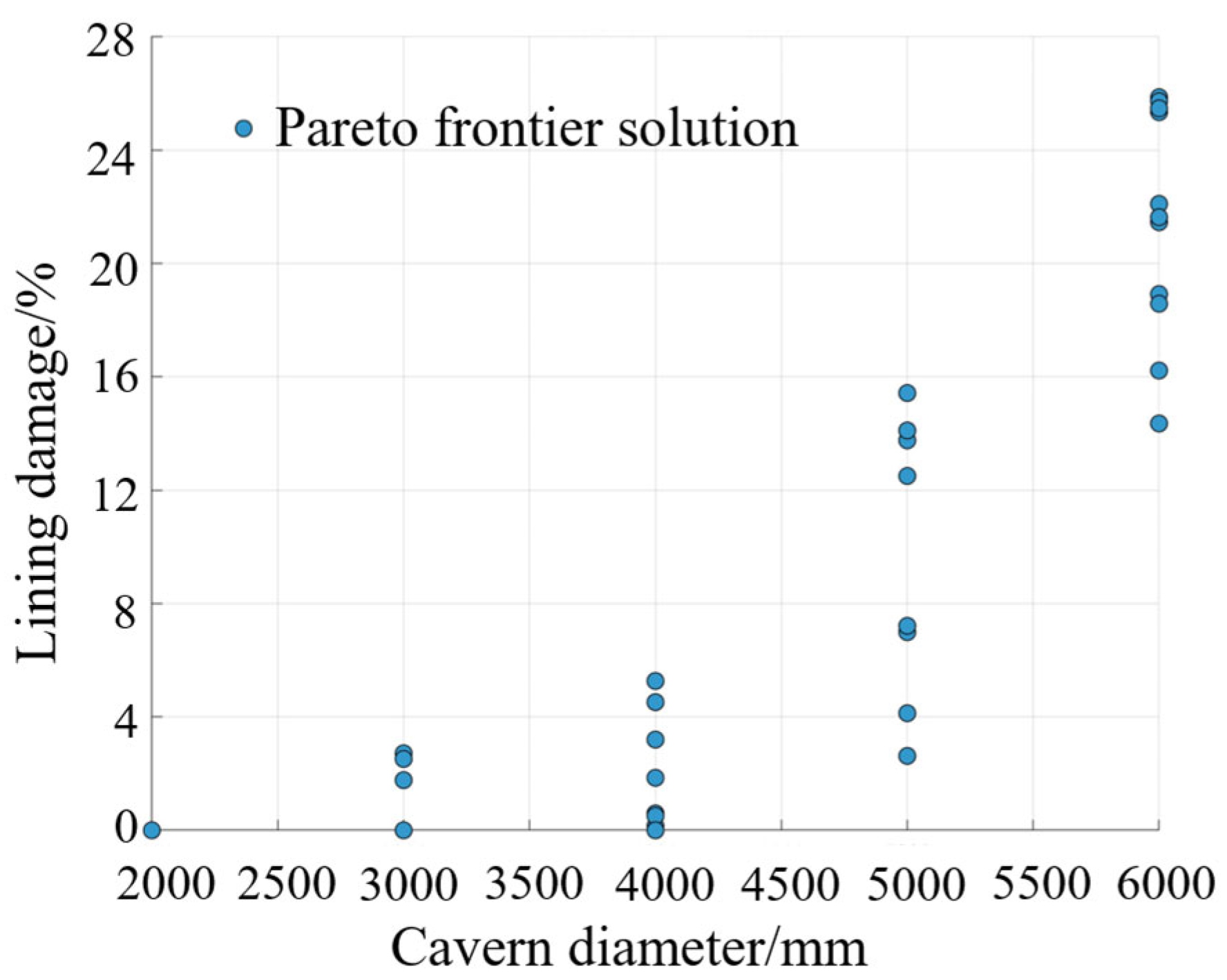
- An MOPSO framework based on PSO-BP surrogate model was implemented to balance lining tensile damage against cavern diameter. The Pareto front confirms that the R-SFC lining is advantageous at cavern diameters around 4 m. From this front, two preferred designs within the recommended thickness-to-diameter range are derived for different engineering priorities, one targeting minimum tensile damage and the other targeting a larger cavern diameter for greater storage capacity.
Author Contributions
Funding
Institutional Review Board Statement
Informed Consent Statement
Data Availability Statement
Conflicts of Interest
Abbreviations
| CAES | Compressed air energy storage |
| EDZ | Excavation-disturbed zone |
| FRP | Fibre-reinforced plastic |
| MOPSO | Multi-objective particle swarm optimisation |
| PSO | Particle swarm optimisation |
| PSO-BP | Particle swarm optimisation-backpropagation |
| R-SFC | Reinforced-steel fibre concrete |
| SFRC | Steel fibre-reinforced concrete |
Appendix A

| Number | Steel Fibre Volume Fraction/% | Lining Thickness/mm | Cavern Diameter/mm | Outer Ring Rebar Diameter/mm | Inner Ring Rebar Diameter/mm | Lining Damage/% |
|---|---|---|---|---|---|---|
| 1 | 0.5 | 300 | 2000 | 18 | 18 | 6.62 |
| 2 | 0.5 | 400 | 4000 | 28 | 25 | 16.2 |
| 3 | 0.5 | 500 | 6000 | 25 | 20 | 26.0 |
| 4 | 0.5 | 600 | 3000 | 22 | 28 | 10.5 |
| 5 | 0.5 | 300 | 5000 | 20 | 22 | 24.8 |
| 6 | 1 | 300 | 6000 | 22 | 25 | 27.5 |
| 7 | 1 | 400 | 3000 | 20 | 20 | 12.3 |
| 8 | 1 | 500 | 5000 | 18 | 28 | 21.9 |
| 9 | 1 | 600 | 2000 | 28 | 22 | 0.0 |
| 10 | 1 | 400 | 4000 | 25 | 18 | 20.4 |
| 11 | 1.5 | 300 | 5000 | 28 | 20 | 23.1 |
| 12 | 1.5 | 400 | 2000 | 25 | 28 | 0.0 |
| 13 | 1.5 | 500 | 4000 | 22 | 22 | 16.2 |
| 14 | 1.5 | 600 | 6000 | 20 | 18 | 26.7 |
| 15 | 1.5 | 500 | 3000 | 18 | 25 | 8.24 |
| 16 | 0.5 | 300 | 4000 | 20 | 28 | 18.1 |
| 17 | 0.5 | 400 | 6000 | 18 | 22 | 28.4 |
| 18 | 0.5 | 500 | 3000 | 28 | 18 | 11.9 |
| 19 | 0.5 | 600 | 5000 | 25 | 25 | 20.8 |
| 20 | 1 | 600 | 2000 | 22 | 20 | 0.389 |
| 21 | 1 | 300 | 3000 | 25 | 22 | 11.9 |
| 22 | 1 | 400 | 5000 | 22 | 18 | 24.6 |
| 23 | 1.5 | 500 | 2000 | 20 | 25 | 0.0 |
| 24 | 1.5 | 600 | 4000 | 18 | 20 | 16.7 |
| 25 | 1.5 | 400 | 6000 | 28 | 28 | 23.6 |
| 26 | 0.5 | 300 | 3000 | 20 | 20 | 14.8 |
| 27 | 0.5 | 400 | 5000 | 25 | 22 | 22.5 |
| 28 | 0.5 | 500 | 5000 | 20 | 20 | 24.5 |
| 29 | 0.5 | 600 | 6000 | 25 | 25 | 28.8 |
| 30 | 1 | 300 | 2000 | 25 | 22 | 1.4 |
| 31 | 1 | 300 | 5000 | 25 | 28 | 22.3 |
| 32 | 1 | 400 | 6000 | 18 | 25 | 27.9 |
| 33 | 1 | 500 | 3000 | 22 | 25 | 9.31 |
| 34 | 1 | 600 | 6000 | 28 | 28 | 22.6 |
| 35 | 1.5 | 300 | 3000 | 18 | 20 | 13.4 |
| 36 | 1.5 | 300 | 4000 | 25 | 22 | 17.0 |
| 37 | 1.5 | 400 | 4000 | 25 | 28 | 14.7 |
| 38 | 1.5 | 500 | 5000 | 20 | 25 | 21.3 |
| 39 | 1.5 | 600 | 5000 | 28 | 20 | 19.7 |
| 40 | 0.5 | 400 | 3000 | 20 | 20 | 13.4 |
| 41 | 0.5 | 500 | 4000 | 25 | 22 | 17.7 |
| 42 | 0.5 | 600 | 4000 | 22 | 18 | 19.8 |
| 43 | 1 | 400 | 2000 | 18 | 18 | 3.36 |
| 44 | 1 | 500 | 6000 | 28 | 22 | 25.0 |
| 45 | 1 | 600 | 4000 | 20 | 25 | 17.1 |
| 46 | 1.5 | 400 | 5000 | 22 | 28 | 21.0 |
| 47 | 1.5 | 500 | 6000 | 28 | 28 | 22.2 |
| 48 | 1.5 | 600 | 3000 | 18 | 18 | 10.4 |
References
- IEA. World Energy Outlook 2022; International Energy Agency (IEA): Paris, France, 2022. [Google Scholar]
- IEA. Renewables 2022; International Energy Agency (IEA): Paris, France, 2022. [Google Scholar]
- Wei, X.X.; Ban, S.N.; Shi, X.L.; Li, P.; Li, Y.P.; Zhu, S.J.; Yang, K.; Bai, W.Z.; Yang, C.H. Carbon and energy storage in salt caverns under the background of carbon neutralization in China. Energy 2023, 272, 127120. [Google Scholar] [CrossRef] [Scilit]
- Denholm, P.; Kulcinski, G.L. Life cycle energy requirements and greenhouse gas emissions from large scale energy storage systems. Energy Convers. Manag. 2004, 45, 2153–2172. [Google Scholar] [CrossRef] [Scilit]
- Chen, Y.Z.; Hill, D.; Billings, B.; Hedengren, J.; Powell, K. Hydrogen underground storage for grid electricity storage: An optimization study on techno-economic analysis. Energy Convers. Manag. 2024, 322, 119115. [Google Scholar] [CrossRef] [Scilit]
- Killer, M.; Farrokhseresht, M.; Paterakis, N.G. Implementation of large-scale Li-ion battery energy storage systems within the EMEA region. Appl. Energy 2020, 260, 114166. [Google Scholar] [CrossRef] [Scilit]
- Minakshi, M.; Nallathamby, K.; Mitchell, D.R.G. Electrochemical characterization of an aqueous lithium rechargeable battery: The effect of CeO2 additions to the MnO2 cathode. J. Alloys Compd. 2009, 479, 87–90. [Google Scholar] [CrossRef] [Scilit]
- Zhao, H.R.; Wu, Q.W.; Hu, S.J.; Xu, H.H.; Rasmussen, C.N. Review of energy storage system for wind power integration support. Appl. Energy 2015, 137, 545–553. [Google Scholar] [CrossRef] [Scilit]
- Fan, C.H.; Li, M.J.; Li, M.J.; Chen, L.J.; Liu, Z.B. Performance analysis and optimization of an adiabatic compressed air energy storage system coupled with the packed-bed thermal energy storage device. Energy 2025, 324, 135939. [Google Scholar] [CrossRef] [Scilit]
- Qiao, M.M.; Hao, R.J.; Zhang, H.S.; Li, H.L.; Zhang, Y.P.; Liu, H.Y.; Duan, C.H.; Qin, J.Y. Energy, exergy, economic and environmental (4E) evaluation of an improved cogeneration system based on compressed air energy storage and absorption heat pump. Energy 2025, 331, 136797. [Google Scholar] [CrossRef] [Scilit]
- Ge, G.Q.; Cai, X.C.; Sun, H.; Zhang, Y.F.; Wang, H.R.; Li, R.X. Optimization design of an adiabatic compressed air energy storage system with sliding pressure operation and packed bed thermal energy storage based on a one-dimensional loss model. Energy Convers. Manag. 2025, 328, 119626. [Google Scholar] [CrossRef] [Scilit]
- Shi, W.J.; Liang, Y.R.; Ding, R.C.; Su, W.; Lin, X.X.; Wang, J.Q. Thermal-economic performance analysis of AA-CAES system with multi-objective optimization. J. Energy Storage 2025, 117, 116177. [Google Scholar] [CrossRef] [Scilit]
- Cheayb, M.; Gallego, M.M.; Tazerout, M.; Poncet, S. A techno-economic analysis of small-scale trigenerative compressed air energy storage system. Energy 2022, 239, 121842. [Google Scholar] [CrossRef] [Scilit]
- Zhang, Y.; Liu, J.X.; Yin, S.Z.; Su, C.Q.; Liu, Z. Design and performance analysis of a novel compressed air–liquid CO2 energy storage. Energy Convers. Manag. 2024, 301, 118068. [Google Scholar] [CrossRef] [Scilit]
- Wallace, L.R.; Cai, Z.; Zhang, H.; Guo, C.B. Numerical investigations into the comparison of hydrogen and gas mixtures storage within salt caverns. Energy 2024, 311, 133369. [Google Scholar] [CrossRef] [Scilit]
- Han, Y.; Ma, H.; Yang, C.; Li, H.; Yang, J. The mechanical behavior of rock salt under different confining pressure unloading rates during compressed air energy storage (CAES). J. Pet. Sci. Eng. 2021, 196, 107676. [Google Scholar] [CrossRef] [Scilit]
- Liu, W.; Jiang, D.Y.; Chen, J.; Daemen, J.J.K.; Tang, K.; Wu, F. Comprehensive feasibility study of two-well-horizontal caverns for natural gas storage in thinly-bedded salt rocks in China. Energy 2018, 143, 1006–1019. [Google Scholar] [CrossRef] [Scilit]
- Wang, X.P.; Wang, J.B.; Zhang, Q.; Song, Z.P.; Liu, X.R.; Feng, S.J. Long-term stability analysis and evaluation of salt cavern compressed air energy storage power plant under creep-fatigue interaction. J. Energy Storage 2022, 55, 105843. [Google Scholar] [CrossRef] [Scilit]
- Ma, Y.; Rao, Q.H.; Huang, D.Y.; Li, P.; Yi, W.; Sun, D.L. A new theoretical model of thermo-gas-mechanical (TGM) coupling field for underground multi-layered cavern of compressed air energy storage. Energy 2022, 257, 124646. [Google Scholar] [CrossRef] [Scilit]
- Lu, M. Finite element analysis of a pilot gas storage in rock cavern under high pressure. Eng. Geol. 1998, 49, 353–361. [Google Scholar] [CrossRef] [Scilit]
- Qin, S.; Xia, C.; Zhou, S. Air tightness of compressed air storage energy caverns with polymer sealing layer subjected to various air pressures. J. Rock Mech. Geotech. Eng. 2023, 15, 2105–2116. [Google Scholar] [CrossRef] [Scilit]
- Jiang, Z.M.; Li, P.; Tang, D.; Zhao, H.B.; Li, Y. Experimental and Numerical Investigations of Small-Scale Lined Rock Cavern at Shallow Depth for Compressed Air Energy Storage. Rock Mech. Rock Eng. 2020, 53, 2671–2683. [Google Scholar] [CrossRef] [Scilit]
- Kim, H.M.; Rutqvist, J.; Ryu, D.W.; Choi, B.H.; Sunwoo, C.; Song, W.K. Exploring the concept of compressed air energy storage (CAES) in lined rock caverns at shallow depth: A modeling study of air tightness and energy balance. Appl. Energy 2012, 92, 653–667. [Google Scholar] [CrossRef] [Scilit]
- Li, P.; Kang, H.; Zhu, Q.; Wu, Y.; Zhang, J.; Fan, L.Y.; Wang, Z. Numerical and experimental investigations of concrete lined compressed air energy storage system. J. Clean. Prod. 2023, 390, 136153. [Google Scholar] [CrossRef] [Scilit]
- Fischer, G.; Li, V.C. Effect of fiber reinforcement on the response of structural members. Eng. Fract. Mech. 2007, 74, 258–272. [Google Scholar] [CrossRef] [Scilit]
- Khan, M.; Cao, M.; Ali, M. Cracking behaviour and constitutive modelling of hybrid fibre reinforced concrete. J. Build. Eng. 2020, 30, 101272. [Google Scholar] [CrossRef] [Scilit]
- Meng, G.; Liu, G.; Su, S.; Li, H.T.; Liang, J.Y.; Zhu, X.; Cai, M.L. Optimization of reinforced-steel fiber concrete secondary lining design for mountain caverns: Field tests and numerical simulations. Constr. Build. Mater. 2025, 477, 141301. [Google Scholar] [CrossRef] [Scilit]
- Geng, X.; Sun, G.H.; Wu, K.; Yao, Y.F.; Ji, W.D.; Yu, X.Y.; Wang, J. Thermodynamic analysis of lined rock caverns for initial inflation and cyclic operational conditions in compressed air energy storage. J. Energy Storage 2024, 99, 113253. [Google Scholar] [CrossRef] [Scilit]
- Rutqvist, J.; Kim, H.M.; Ryu, D.W.; Synn, J.H.; Song, W.K. Modeling of coupled thermodynamic and geomechanical performance of underground compressed air energy storage in lined rock caverns. Int. J. Rock Mech. Min. Sci. 2012, 52, 71–81. [Google Scholar] [CrossRef] [Scilit]
- Wan, F.; Jiang, Z.; Tian, X.; Konietzky, H.; Xiao, Z.Z. A thermo-hydro-mechanical damage model for lined rock cavern for compressed air energy storage. J. Energy Storage 2024, 78, 110186. [Google Scholar] [CrossRef] [Scilit]
- Zhang, X.; Liu, W.; Jiang, D.Y.; Qiao, W.B.; Liu, W.B.; Zhang, N.; Fan, J.Y. Investigation on the influences of interlayer contents on stability and usability of energy storage caverns in bedded rock salt. Energy 2021, 231, 120968. [Google Scholar] [CrossRef] [Scilit]
- Xia, C.; Xu, Y.; Zhou, S.; Qin, S.K.; He, X.H. Fracture initiation and propagation in the lined underground caverns for compressed air energy storage: Coupled thermo-mechanical phase-field modeling. Comput. Geotech. 2023, 157, 105329. [Google Scholar] [CrossRef] [Scilit]
- Liu, X.; Sun, Q.H.; Song, W.; Bao, Y.H. Numerical modeling and parametric study of hybrid fiber-rebar reinforced concrete tunnel linings. Eng. Struct. 2022, 251, 113565. [Google Scholar] [CrossRef] [Scilit]
- Lu, Q.; Xu, Y.; Xia, C.; Liu, S. Mechanical response of fiber reinforced flexible concrete for compressed air energy storage underground caverns. Rock Soil Mech. 2024, 45, 3566–3575. [Google Scholar] [CrossRef] [Scilit]
- Shao, J.; Fan, Z.; Huang, Y.Y.; Zhan, Y.L.; Cai, Q.H. Multi-objective optimization of double-walled steel cofferdams based on response surface methodology and particle swarm optimization algorithm. Structures 2023, 49, 256–266. [Google Scholar] [CrossRef] [Scilit]
- Hu, J.H.; Zhou, X.H.; Liu, J.P.; Shan, W.C.; Qi, H.T.; Chen, W.; Zhang, Y.J. Intelligent design of shear wall structures based on BIM and multi-objective genetic algorithm. J. Build. Eng. 2025, 104, 112284. [Google Scholar] [CrossRef] [Scilit]
- Liu, C.; Sun, Z. Green flexible production and intelligent factory building structure design based on improved ant colony algorithm. Therm. Sci. Eng. Prog. 2024, 53, 102753. [Google Scholar] [CrossRef] [Scilit]
- Huang, D.Y.; Ma, Y.; Rao, Q.H.; Yi, W.; Yang, W.T.; Li, P. A new multi-objective optimization model of multi-layer prestressed lining cavern for compressed air energy storage. J. Cent. South Univ. 2023, 30, 3855–3866. [Google Scholar] [CrossRef] [Scilit]
- Liu, X.Y.; Yang, J.P.; Yang, C.H.; Zhang, Z.Y.; Chen, W.Z. Numerical simulation on cavern support of compressed air energy storage (CAES)considering thermo-mechanical coupling effect. Energy 2023, 282, 128916. [Google Scholar] [CrossRef] [Scilit]
- Kushnir, R.; Dayan, A.; Ullmann, A. Temperature and pressure variations within compressed air energy storage caverns. Int. J. Heat Mass Transf. 2012, 55, 5616–5630. [Google Scholar] [CrossRef] [Scilit]
- Grassl, P.; Xenos, D.; Nyström, U.; Rempling, R.; Gylltoft, K. CDPM2: A damage-plasticity approach to modelling the failure of concrete. Int. J. Solids Struct. 2013, 50, 3805–3816. [Google Scholar] [CrossRef] [Scilit]
- GB/T 50010-2010; Code for Design of Concrete Structures. China Architecture & Building Press: Beijing, China, 2024.
- Zhang, H. Study on Strength and Flexural Toughness of Steel Fiber Reinforced Concrete. Master’s Thesis, Zhengzhou University, Zhengzhou, China, 2011. [Google Scholar]
- Li, F.C. Numerical Simulation and Structural Optimization of Steel Fiber-Reinforced Concrete Lining Structures in Underground Gas Storage Caverns. Master’s Thesis, Xi’an University of Technology, Xi’an, China, 2025. [Google Scholar]
- Kazemi, M.T.; Fazileh, F.; Ebranhiminezhad, M.A. Cohesive crack model and fracture energy of steel-fiber-reinforced-concrete notched cylindrical specimens. J. Mater. Civ. Eng. 2007, 19, 884–890. [Google Scholar] [CrossRef] [Scilit]
- Ren, Z.J.; Wang, T.C.; Wu, S.C.; Cheng, H.Y.; Geng, X.J.; Pu, S.J.; Wang, T. Economic and environmental evaluation of the effectiveness of steel fiber–reinforced concrete lining: A case study. J. Mater. Civ. Eng. 2025, 37, 05025009. [Google Scholar] [CrossRef] [Scilit]
- Cao, J.Z.; Zhang, Y.; Yuan, H.; Mei, N. A Sustainable Approach to Vehicle LNG Tank Design Using MOPSO and 3D Modeling. Sustainability 2025, 17, 9834. [Google Scholar] [CrossRef] [Scilit]








| Limitation | Specific Content | Impact on Results | Subsequent Improvement Direction |
|---|---|---|---|
| Geometric simplification | 2D plane strain assumption, ignoring the end effect of the cavity, and 3D stress redistribution | Underestimating the tensile damage at the end of the lining, the predicted damage value is 5–10% lower than that of 3D | Establish a 3D thermos-mechanical coupling model to quantify end effects |
| Interface simplification | Neglecting the bond slip between the steel lining and the surrounding rock | Overestimating the stress transmission efficiency and damage control capability of the lining | Introduce spring elements to simulate adhesive slip and calibrate slip parameters |
| Material simplification | SFRC homogenization treatment, no micromechanical model; isotropic assumption of the surrounding rock | Unable to characterise the microscale bridging effect of steel fibres, the strength of the surrounding rock is slightly overestimated | Establish the SFRC micromechanical model and introduce rock anisotropy parameters |
| Load simplification | Uniform distribution of pressure/temperature inside the tunnel, ignoring local load fluctuations | Underestimating the damage caused by local stress concentration, suitable for uniform inflation and deflation conditions | Introducing non-uniform load boundaries to analyse the damage effects of local loads |
| Steel Fibre Volume Fraction/% | Compressive Strength Ratio | Tensile Strength Ratio | Elastic Modulus Ratio |
|---|---|---|---|
| 0.0 | 1.00 | 1.00 | 1.00 |
| 0.5 | 1.09 | 1.23 | 1.02 |
| 1.0 | 1.10 | 1.44 | 1.06 |
| 1.5 | 1.08 | 1.63 | 1.08 |
| Lining Thickness /mm | Concrete | 0.5% SFRC | 1% SFRC | 1.5% SFRC |
|---|---|---|---|---|
| 300 | 267 | 2937 | 4005 | 5607 |
| 400 | 376 | 4136 | 5640 | 7896 |
| 500 | 242 | 2662 | 3630 | 5082 |
| 600 | 245 | 2695 | 3675 | 5145 |
| Materials | ρ/kg·m−3 | k/W·m−1·K−1 | chs/J·kg−1·K−1 | α/10−5·K−1 | E/GPa | μ | c/MPa | φ/° |
|---|---|---|---|---|---|---|---|---|
| Rock | 2650 | 2.98 | 773 | 1 | 45 | 0.15 | 3 | 55 |
| EDZ | 2650 | 2.87 | 760 | 1 | 40 | 0.15 | 2.8 | 50 |
| SFRC | 2500 | 1.74 | 800 | 1 | 33.1~35.25 | 0.168 | - | - |
| FRP | 2000 | 0.4 | 384 | 0.55 | 3.9 | 0.20 | - | - |
| Rebar | 7800 | 50 | 465 | - | 200 | 0.3 | - | - |
| Type | Lining Thickness /mm | Rebar Diameter /mm | Cavern Diameter /mm | Steel Fibre Volume Fraction/% | EDZ Radius /mm |
|---|---|---|---|---|---|
| C-0 | 500 | Double ring 32 | 3000 | 0.0 | 4000 |
| SF-1 | 500 | Double ring 18 | 3000 | 0.5 | 4000 |
| SF-2 | 500 | Double ring 18 | 3000 | 1.0 | 4000 |
| SF-3 | 500 | Double ring 18 | 3000 | 1.5 | 4000 |
| Type | Lining Thickness /mm | Steel Fibre Volume Fraction/% | Cavern Diameter /mm | Rebar Diameter /mm | EDZ Radius /mm |
|---|---|---|---|---|---|
| TK-1 | 300 | 1.5 | 3000 | Double ring 18 | 4000 |
| TK-2 | 400 | 1.5 | 3000 | Double ring 18 | 4000 |
| TK-3 | 600 | 1.5 | 3000 | Double ring 18 | 4000 |
| DJ-1 | 500 | 1.5 | 2000 | Double ring 18 | 3500 |
| DJ-2 | 500 | 1.5 | 4000 | Double ring 18 | 4500 |
| DJ-3 | 500 | 1.5 | 5000 | Double ring 18 | 5000 |
| DJ-4 | 500 | 1.5 | 6000 | Double ring 18 | 5500 |
| GJ-1 | 500 | 1.5 | 5000 | Inner ring 25, outer ring 18 | 5000 |
| GJ-2 | 500 | 1.5 | 5000 | Inner ring 18, outer ring 25 | 5000 |
| GJ-3 | 500 | 1.5 | 5000 | Double ring 25 | 5000 |
| Parameter Name | Values Range | Step Size |
|---|---|---|
| Steel fibre volume fraction/% | [0.5, 1.5] | 0.5 |
| Lining thickness/mm | [300, 600] | 100 |
| Cavern diameter/mm | [2000, 6000] | 1000 |
| Outer ring rebar diameter/mm | [18, 28] | Based on existing rebar specifications [42] |
| Inner ring reinforcing bar diameter/mm | [18, 28] | Based on existing rebar specifications [42] |
| Type | Steel Fibre Volume Fraction/% | Lining Thickness/mm | Cavern Diameter/mm | Outer Ring Rebar Diameter/mm | Inner Ring Rebar Diameter/mm | Lining Damage/% |
|---|---|---|---|---|---|---|
| 1 | 0.5 | 400 | 4000 | 25 | 25 | 18.111698 |
| 2 | 1 | 400 | 6000 | 20 | 18 | 26.266937 |
| 3 | 1 | 400 | 6000 | 25 | 22 | 26.066937 |
| 4 | 1 | 600 | 6000 | 20 | 22 | 22.343342 |
| 5 | 1.5 | 500 | 4000 | 28 | 22 | 4.254951 |
| 6 | 1.5 | 600 | 5000 | 25 | 20 | 6.862758 |
| 7 | 1.5 | 500 | 6000 | 28 | 25 | 19.580517 |
| 8 | 1.5 | 500 | 6000 | 28 | 18 | 21.704188 |
| Type | Steel Fibre Volume Fraction/% | Lining Thickness/mm | Cavern Diameter/mm | Outer Ring Rebar Diameter/mm | Inner Ring Rebar Diameter/mm | Optimise the Predicted Value | Numerical Simulation Computed Values |
|---|---|---|---|---|---|---|---|
| Lining Damage/% | Lining Damage/% | ||||||
| 1 | 0.5 | 400 | 4000 | 25 | 25 | 18.111698 | 16.6 |
| 3 | 1 | 400 | 6000 | 25 | 22 | 26.066937 | 23.6 |
| 5 | 1.5 | 500 | 4000 | 28 | 22 | 4.254951 | 3.97 |
Disclaimer/Publisher’s Note: The statements, opinions and data contained in all publications are solely those of the individual author(s) and contributor(s) and not of MDPI and/or the editor(s). MDPI and/or the editor(s) disclaim responsibility for any injury to people or property resulting from any ideas, methods, instructions or products referred to in the content. |
© 2026 by the authors. Licensee MDPI, Basel, Switzerland. This article is an open access article distributed under the terms and conditions of the Creative Commons Attribution (CC BY) license.
Share and Cite
Zhang, S.; Li, F.; Zhu, Y.; Li, Z.; Yang, R.; Shao, Y.; Wang, B. Plastic Damage Analysis and Structural Optimisation of Reinforced-Steel Fibre Concrete Lining for Underground Gas Storage Caverns. Sustainability 2026, 18, 5096. https://doi.org/10.3390/su18105096
Zhang S, Li F, Zhu Y, Li Z, Yang R, Shao Y, Wang B. Plastic Damage Analysis and Structural Optimisation of Reinforced-Steel Fibre Concrete Lining for Underground Gas Storage Caverns. Sustainability. 2026; 18(10):5096. https://doi.org/10.3390/su18105096
Chicago/Turabian StyleZhang, Shuai, Fuchun Li, Yiyun Zhu, Zhe Li, Rong Yang, Yang Shao, and Bingyi Wang. 2026. "Plastic Damage Analysis and Structural Optimisation of Reinforced-Steel Fibre Concrete Lining for Underground Gas Storage Caverns" Sustainability 18, no. 10: 5096. https://doi.org/10.3390/su18105096
APA StyleZhang, S., Li, F., Zhu, Y., Li, Z., Yang, R., Shao, Y., & Wang, B. (2026). Plastic Damage Analysis and Structural Optimisation of Reinforced-Steel Fibre Concrete Lining for Underground Gas Storage Caverns. Sustainability, 18(10), 5096. https://doi.org/10.3390/su18105096