Article

Design Optimization and Field Validation of Industrial Fans with CFD for Cement Production: Performance, Energy Savings, and Environmental Benefits

1
Department of Civil Engineering, Faculty of Engineering, Igdir University, Igdir 76000, Türkiye
2
Department of Mechanical Engineering, Muş Alparslan University, Muş 49250, Türkiye
3
Department of Mechanical Engineering, Bilecik Șeyh Edebali University, Bilecik 11210, Türkiye
4
Alfer Engineering, Ankara 06934, Türkiye
5
Yurt Cement Inc., Muş 49250, Türkiye
*
Author to whom correspondence should be addressed.
Sustainability 2025, 17(22), 10279; https://doi.org/10.3390/su172210279
Submission received: 16 October 2025 / Revised: 13 November 2025 / Accepted: 14 November 2025 / Published: 17 November 2025
(This article belongs to the Special Issue Sustainable Energy: Research on Heat Transfer and Energy Systems)

Abstract

This study presents a computational–experimental assessment of two industrial centrifugal fans used in cement production, focusing on aerodynamic optimization and energy efficiency validation. The first case concerns a Farin Kiln Filter Fan initially constrained by existing inlet duct geometry, which caused vortex formation, flow asymmetry, and a pressure loss exceeding 15%. CFD analyses identified major inlet vortices and asymmetric splitter loading, guiding a redesigned configuration with an expanded fan body (1982–2520 mm), an increased outlet width (1808–1858 mm), and a vortex breaker to stabilize inlet flow. CFD simulations indicated a flow rate of 601,241 m3/h, static pressure of 2200 Pa, and total pressure of 2580 Pa, achieving an 83% efficiency. Field validation confirmed a 34.4% reduction in shaft power, 30% decrease in torque, and 4% gain in efficiency, corresponding to 449 MWh/year energy savings and 180 t CO2/year emission reduction, assuming 8000 operational hours. The second case involves an Induced Draft (ID) Fan designed for 441,643 m3/h flow at 990 rpm. Transient CFD simulations using the SST k–ω model captured rotor–stator interaction and confirmed the effectiveness of the design revisions in suppressing swirl and flow separation. The optimized design achieved 8653 Pa static pressure, 9203 Pa total pressure, and 83% efficiency under design conditions. Field measurements showed a 26.2% drop in shaft power and 19.6% improvement in efficiency, yielding 2527 MWh/year energy savings and an estimated 1011 t CO2/year emission reduction. Overall, the CFD-guided redesign framework demonstrated strong alignment between simulations and field measurements, highlighting the method’s practical relevance for improving fan performance and energy sustainability in industrial systems.

1. Introduction

Fan systems are fundamental components that underpin numerous essential processes within industrial facilities, including fluid transportation, ventilation, cooling, and gas emission management [1]. Industrial-scale centrifugal fans meet high volumetric flow and pressure specifications, thereby directly impacting process efficiency [2]. Particularly in cement manufacturing, fans are key elements in operations such as kiln feeding, filtration systems, and flue gas transfer, which markedly influence both production capacity and energy consumption [3,4]. Globally, cement production encounters significant challenges due to heightened energy requirements and carbon emissions, which are considered primary barriers to sustainability objectives. Consequently, the development of energy-efficient equipment remains a central focus of research and innovation within the sector. Designing fan systems for the cement industry involves complex considerations, including flow resistance, temperature effects, particulate loads, and system pressure demands [5,6]. Recent studies have emphasized that redesigning fan components, especially impellers, can significantly improve efficiency in cement applications, with reported performance gains exceeding 15% when CFD-supported geometry modifications are implemented [7]. Optimizing fan performance reduces energy consumption and improves system reliability, process stability, and product quality. Due to its intensive energy requirements and high carbon emissions, global cement production is considered a significant obstacle to sustainable development goals [8]. The International Energy Agency reports classify cement as one of the most energy-intensive industries. The design of energy-efficient equipment and the optimization of existing systems are among the priority R&D topics in the sector [9]. Fan systems, in particular, account for a significant portion of a facility’s total electricity consumption, so any improvements to this equipment directly translate into energy savings and emissions reductions [10]. The parameters to be considered in the design of fan systems are quite diverse. Flow resistance, temperature effects, particle load, gas density, and system pressure requirements directly impact fan performance [11]. Furthermore, process stability and product quality depend on the constant and uniform flow conditions provided by the fan. For example, raw meal kiln feed fans transport the ground meal mixture to the kiln at a specific flow rate and pressure [12,13]. Flow separations, vortex structures at the inlet, or asymmetric flow distributions in the outlet channel that may occur in these systems reduce fan efficiency and negatively impact kiln performance and increase energy consumption [14,15]. Therefore, one of the primary goals of modern fan design is to develop aerodynamic solutions that minimize flow separation and vortex formation and optimize the inlet and outlet flow profile [16,17]. Energy efficiency policies implemented in recent years also directly impact the industry’s design and selection of fan systems. In Turkey, the National Energy Efficiency Action Plan, implemented by the Ministry of Industry and Technology and the Ministry of Energy and Natural Resources, lists fan systems, pump systems, and motor drive systems among the priority areas for improvement in the industry [17,18]. This has made fan design and modernization a current and strategic issue, particularly in energy-intensive industries like cement. The Industry 4.0 transformation process supports this trend, allowing for closer fan performance monitoring through digitalization, sensor-based monitoring, and numerical modelling [19,20,21]. CFD (Computational Fluid Dynamics)-supported engineering applications are increasingly used in new fan designs and retrofit projects for existing systems. Traditional fan design methodologies are based mainly on empirical correlations and experimental tests. Recent studies show that advanced design strategies such as 3D inverse modeling, free and non-free vortex optimization, and circumferential sweep of blades significantly improve axial and centrifugal fan performance [22,23]. In addition, parametric investigations reveal that geometry alterations on splitter plates, impeller blades, and volute tongues can enhance flow stability and efficiency by minimizing turbulence and flow asymmetry at the rotor–stator interface [24]. However, detailed experimental investigations of flow separation, rotor-stator interactions, turbulent transition zones, and complex vortex structures in high-capacity centrifugal fans are quite costly and often limited [25,26,27]. In this regard, CFD analyses enable detailed modeling of fan geometry, simulation of different operating conditions, and systematic testing of design revisions. Thanks to transient solutions, the complex flow patterns resulting from rotor motion and the interactions at the rotor-stator interface can be calculated with high accuracy [28,29,30]. The success of fan systems in the cement industry depends not only on design capacity but also on the actual operating conditions of the plant. The primary factors that complicate fan design are the high temperature, low density, and particulate matter of kiln exhaust gases. For raw meal kiln feed fans, ensuring a uniform speed profile is a critical requirement, and separation zones that may form in the inlet pocket can significantly reduce fan efficiency [31,32]. Therefore, customized engineering approaches supported by CFD analyses that take into account industry-specific operating conditions are crucial [33]. While studies demonstrate that CFD is a powerful tool in design and optimization processes, field validation of such studies is often limited [34]. However, in industrial applications, observing the gains achieved through numerical simulations under real-world operating conditions increases the reliability and applicability of the method [35]. In this regard, field tests following design optimization with CFD provide a fan demonstration of the impacts on energy consumption and efficiency [36]. The literature also observes the increasing use of CFD in centrifugal fan design in recent years. For example, Liu et al. proposed a geometry revision that increased centrifugal fan efficiency by 3% by modeling the rotational flow effect at the rotor–stator interfaces with the SST k–ω turbulence model. These studies demonstrate that CFD guides design decisions in a scientifically sound and cost-effective manner [37]. In heavy industry applications, the performance of fan systems depends not only on the design capacity but also on the actual operating conditions of the plant. In cement plants, kiln outlet gases, with their high temperature and low-density flow characteristics, make fan design difficult [4]. Furthermore, ensuring a constant and smooth speed profile is critical for raw material feed fans to ensure homogeneous conveyance of the ground material. Separation zones in the suction pocket or asymmetric flow distribution in the outlet channel negatively affect fan efficiency and kiln performance [12]. As a result, fan design in the cement sector necessitates a tailored engineering approach backed by CFD analyses and taking industry-specific operating conditions into account. To guarantee energy efficiency and lower the lifecycle costs of industrial fans, recent research has underlined the necessity of integrated design–simulation workflows [38]. For example, Zhou et al. [39] improved energy efficiency and conservation by developing a machine-learning and CFD-based optimization methodology for a diagonal-flow fan. To investigate fan geometry variations, they used Latin Hypercube Design sampling in conjunction with surrogate models and CFD simulations. Verified by extensive experiments, the optimized fan design showed significant power consumption reductions as well as increases in total pressure and efficiency, demonstrating the potential of hybrid ML-CFD workflows to enhance industrial fan performance. Similarly to this, Zhang et al. [40] compared the distributions of pressure and velocity fields under various operating conditions by running steady and unsteady numerical simulations of a multi-blade centrifugal fan. In order to optimize fan internal flow dynamics and performance, their study compared validated CFD results with experimental measurements. This comparison was especially helpful with regard to the selection of turbulence models and pressure oscillations at monitoring points. In order to enhance the overall pressure gain and efficiency performance of centrifugal fans, Venter et al. [41] created a parametric fan blade geometry study that combined CFD analysis with automated optimization algorithms. The study concentrated on blade pitch, outlet angle, and losses at the rotor-stator interface, including aeroacoustics effects. Cai et al. [42] conducted transient CFD studies on high-flow ID fan applications; they developed design revision recommendations by modeling rotor rotational effects and flow separations and compared these recommendations with field tests and reported concrete gains in energy efficiency and system performance.
Liu et al. developed a fan design that integrates deep neural networks and genetic algorithms, showing how artificial intelligence can effectively assist in axial fan development under multi-objective criteria [43]. Meanwhile, Motamedi Zokae et al. proposed a multi-point aerodynamic optimization framework for backward-curved impeller fans, considering off-design performance and structural constraints across a wide operational envelope [44].
This study applies CFD-based optimization to improve the performance of a raw meal kiln fan and a clinker kiln ID fan in an operational cement plant. Design revisions such as casing expansion, outlet modification, and vortex suppression are proposed for the raw meal kiln fan, while rotor-stator interactions and swirling flow structures are analyzed in detail for the ID fan. Field tests confirm the validity of the CFD predictions, demonstrating that the optimized designs enhance efficiency and reduce energy demand. The specific objectives are to develop and validate CFD models of existing fan systems using the SST k-ω turbulence model and transient rotor-stator interaction approaches, identify performance-limiting flow phenomena including separation zones and vortex formation through detailed flow field analysis, design and evaluate geometric modifications to address identified flow deficiencies while respecting retrofit constraints, conduct field validation by implementing optimized designs and measuring actual performance improvements, quantify energy savings and economic benefits to establish the business case for CFD-driven fan optimization in cement manufacturing, and provide methodological guidance for practitioners seeking to apply similar CFD-based optimization approaches to industrial fan systems. Overall, this study demonstrates that CFD-supported fan design meets mechanical performance requirements and provides practical benefits for energy efficiency and sustainability, offering a methodological framework for similar applications in the cement industry and other energy-intensive sectors.

2. Materials and Methods

In this study, the design development and computational fluid dynamics (CFD) analyses were conducted for two distinct types of industrial fans intended for deployment at the Yurt Çimento facility (Yurt Cement Inc., Muş, Türkiye). These fans were supplied by Alfer Engineering, (Ankara, Turkey) to meet the specific flow, pressure, and efficiency requirements of the raw-meal and clinker kiln processes. Optimization was performed based on experimentally determined flow rate, pressure, and efficiency metrics during the design process, and the design was subsequently evaluated using numerical methods verified.
A comprehensive modelling and analysis process was conducted for two distinct fan types within this study. The first, the “Raw Meal Kiln Filter Fan”, functions in conjunction with the raw meal (flour) kiln during cement manufacturing. This fan is essential for transporting ground cement raw materials to the kiln and must ensure consistent flow at elevated flow rates. In the analysis performed for this fan, the casing was modified by narrowing it to adapt the existing design to the suction pocket, and the impact of this modification on flow performance was assessed through numerical analysis. The results indicated the occurrence of flow separation and pressure losses within the narrowed casing. The objective was subsequently to attain the desired performance metrics through casing expansion and design modifications. The second fan, the “Clinker Kiln ID Fan”, is integral to the clinker kiln system. It is designed to draw in and exhaust gases from the kiln and must be optimized to handle substantial volumetric flow rates reliably. In this study, a comprehensive CFD model was developed to meet the specified high flow rate requirements for the ID fan, allowing detailed examination of flow behaviour, separation phenomena, vortex structures, and pressure distributions at the impeller inlets and outlets. Consequently, solutions that satisfy design criteria, enhance energy efficiency, and fulfil process requirements for both fan types were devised.
Figure 1 illustrates the component delineations employed in the three-dimensional CAD model and Computational Fluid Dynamics (CFD) analysis of the fan system. The components are categorized into the inlet cone (0, 1), the rotor-stator region (A, B), and the outlet channel (2, 3), thereby permitting the individual modelling of each component with distinct boundary conditions. This segmentation is essential for a comprehensive examination of the rotor-stator interaction as well as the inlet and outlet flow characteristics.

2.1. Fan Geometry and Design Criteria

For the flour kiln fan, the existing casing had to be narrowed by 269 mm on both sides to accommodate the suction pocket. The effect of this narrowing on flow performance was analyzed. Furthermore, the performance losses of the narrowed casing were determined, and the casing geometry was revised and optimised. For the clinker kiln ID fan, analyses were conducted based on design targets corresponding to a volumetric flow rate of 441,643 m3/h. Table 1 shows the targeted design values for both fans.
The flow rate, static pressure, total pressure, shaft power, and efficiency values for the flour oven fan and ID fan are design point data obtained from CFD analyses. Calculations were performed for the final designs of both fans, with optimized geometries, under nominal operating conditions. Volumetric flow rates were determined to meet the design process requirements and were optimised as 601,241 m3/h for the flour oven fan and 441,643 m3/h for the ID fan. Static and total pressure values (in Pa) were calculated using fan inlet and outlet boundary conditions and energy equations in the CFD solutions. Shaft power was obtained by dividing the fluid power (flow rate × total pressure) by the fan efficiency, which was calculated considering aerodynamic losses, the effects of flow guidance elements, and rotor-stator interactions. These parameters constituted the fundamental inputs for the verification and optimization process, ensuring that the fan designs met the performance criteria.

2.2. Numerical Modelling Approach

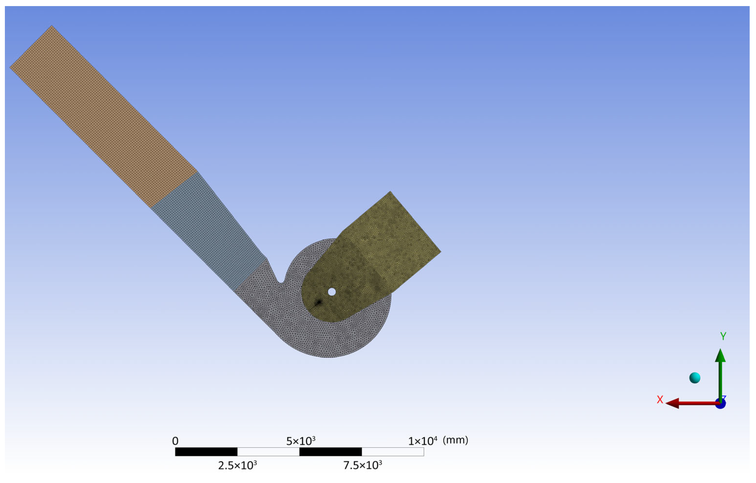
In the study, computational fluid dynamics (CFD) methods were employed to accurately analyze the fan’s fluid dynamics and assess its compliance with design criteria. All analyses were performed using ANSYS CFX 2021 R1 software, and a transient solution approach was adopted. This choice enabled more realistic modelling of the complex and time-dependent flow patterns around the fan blade geometries, particularly in separation regions and turbulent vortex formations. The turbulence model used in the modelling was the Shear Stress Transport (SST) k–ω model. The SST k–ω model was chosen because it offers an accurate solution near the wall at low Reynolds numbers and provides stable results in the free-stream regions at high Reynolds numbers, similar to the k–ε model. This enables a more accurate representation of flow separations around the inlet cone and impeller, as well as interactions between rotating rotor components, and complex turbulent flow patterns in the stator-rotor transition regions. Geometry-specific resolution was applied when creating the mesh. A mesh structure with approximately 17 million elements was designed for the flour kiln fan (Figure 2), while a higher-resolution mesh structure with 28 million elements was used for the ID fan. In the ID fan model, the y+ value was targeted to be approximately 2.8, particularly in the rotor-stator interaction regions and around the impeller, thereby ensuring high accuracy of the turbulence model in near-wall flows. A detailed mesh independence study was carried out by systematically increasing the element count until the changes in total pressure and flow rate at the outlet remained below 1%. This ensured that the numerical results were independent of grid density and validated the mesh resolution. Local mesh refinements were specifically applied around the impeller blade tips, rotor-stator interfaces, and the volute tongue regions, where high velocity gradients and vortex shedding were expected. These refinements improved the accuracy of vortex capturing and separation prediction in the transient simulations. Air was selected as the working fluid considering its relevance to actual operating conditions. The flow was assumed incompressible as the Mach number remained below 0.3 throughout the domain, satisfying the general criterion for neglecting compressibility effects in CFD analyses. The mesh was generated with geometry-specific resolution. An approximate 17 million-element mesh was designed for the flour kiln fan (see Figure 2), whereas a higher-resolution mesh comprising 28 million elements was employed for the ID fan. In the ID fan model, the y+ value was targeted to be approximately 2.8, particularly within the rotor-stator interaction regions and surrounding the impeller, to ensure high accuracy in the turbulence model for near-wall flows. Mesh independence analysis was conducted, and local refinements were implemented in regions with complex geometries. Air served as the fluid medium, and all solutions assumed incompressible flow. This assumption was deemed valid due to the low Mach number characteristic of typical fan operation within a cement plant.
The solution settings employed in the simulations are summarised as follows: The “High Resolution” scheme was selected as the advection method, and the “Second Order Backwards Euler” technique was utilised for time-dependent integration. The interaction between the rotor and stator components was modelled using the Transient Rotor-Stator interface, and the swirling flow patterns generated by the rotor motion were analysed in detail with a solution time step of 0.00050505 s. Two different casing configurations were examined for the flour kiln fan: a narrowed casing and a wide/revised casing. In the narrowed casing model, the impact of reducing the flow area by a total of 269 mm on both sides was evaluated. In this case, the geometry was modelled symmetrically, and half of the total flow rate was defined at the outlet. Due to flow separation and pressure losses observed in the narrow-body analyses, the design was subsequently revised. In the wide-body analysis, the outlet channel width was increased, and a vortex breaker was installed at the inlet pocket to mitigate flow separation and vortex formation, thereby promoting smoother and more efficient flow. Regarding the ID fan analysis, a full-scale model was established based on a volumetric flow rate of 441,643 m3/h (see Figure 3), with the rotor operating at a rotational speed of 990 rpm. A steady flow rate condition was maintained at the outlet boundary, and the total pressure at the inlet was set to 0 Pa. The analysis included the extraction of flow filaments, velocity vectors, and pressure distributions to monitor flow separation and turbulent structures at the impeller inlet and outlet regions. Consequently, the suitability of the fan design relative to the targeted efficiency, pressure, and flow rates was validated through this analysis.

2.3. Boundary Conditions and Solution Parameters

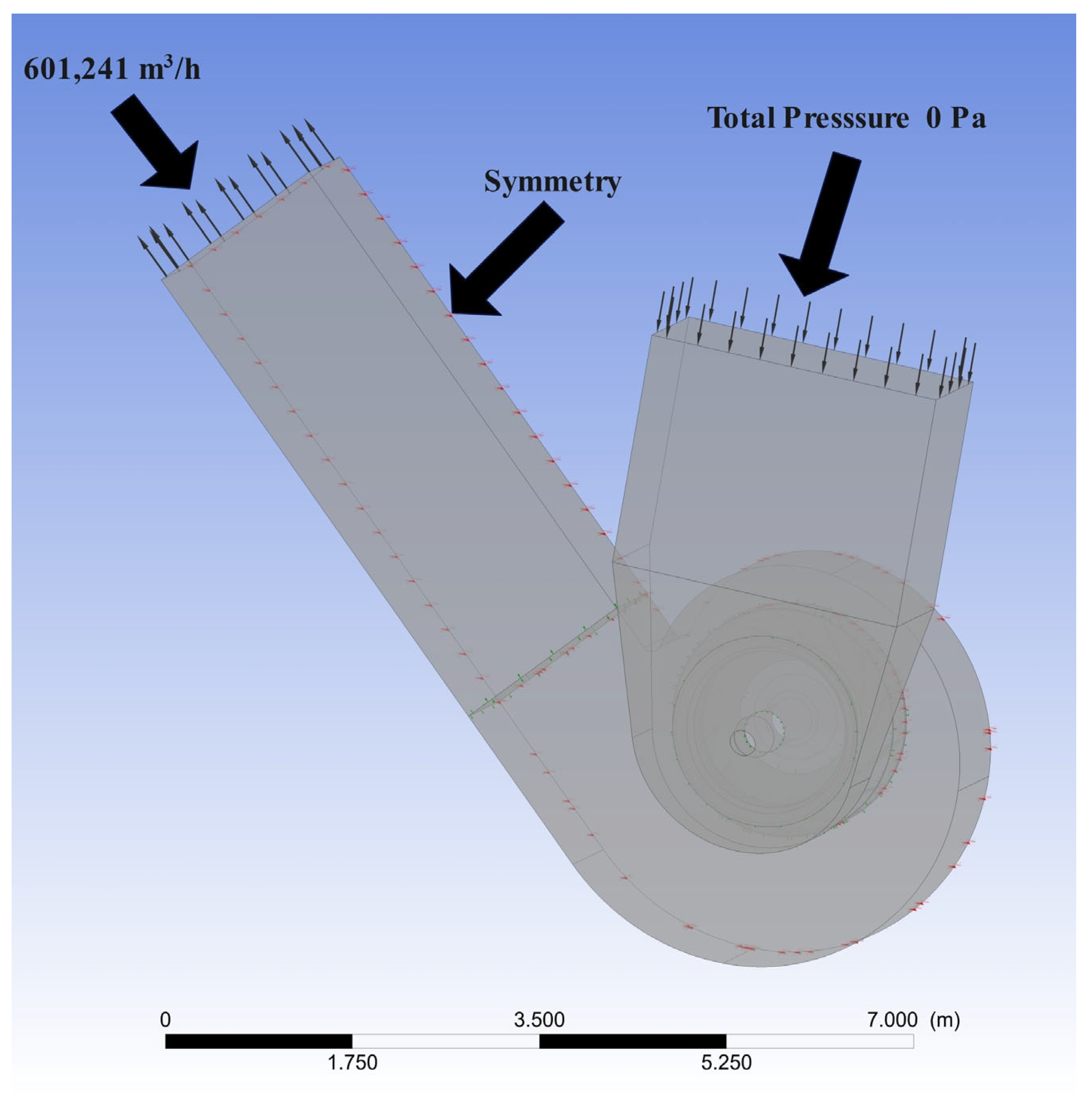
In this study, the boundary conditions and solution parameters for the CFD models were established to accurately represent the operating conditions and design objectives of the fan. Boundary conditions suitable for various flow, pressure, and geometric characteristics were applied to both fan types, with time-dependent solution parameters specified in detail. The boundary conditions for the Flour Kiln Fan are based on fundamental principles pertaining to the narrowed and widened/revised casing configurations and are modelled according to the geometric modifications of the casing. These are illustrated in Figure 4. In the analyses conducted for the Flour Kiln Fan, the total pressure at the inlet boundary was set to 0 Pa. The mass flow rate at the outlet boundary was defined as 61.9612 kg/s. This value was derived from the targeted volumetric flow rate (~601,241 m3/h) and air density (0.745 kg/m3), based on the design requirements. Boundary conditions were selected based on actual design specifications and operating targets. The total pressure at the inlet was fixed at 0 Pa to simulate a suction condition, and the outlet mass flow rate was computed from the required volumetric capacity. This approach ensures repeatability across different fan geometries and enables comparison under standardized flow conditions. Air was employed as the working fluid, and incompressible flow was assumed across all analyses. To further ensure simulation repeatability and mesh quality, the quality metrics such as skewness and orthogonal quality were monitored, with 95% of the elements exhibiting skewness below 0.25. Additionally, the time step for transient analysis was selected based on the blade passing frequency (BPF) to resolve unsteady vortex shedding and rotor–stator interactions accurately. These precautions ensure that both spatial and temporal resolutions were sufficient to capture critical flow physics.
The geometry was modelled symmetrically, with the outlet boundary condition applied solely within half of the area. This methodology facilitated the inclusion of 50% of the total flow rate within the solution, thereby reducing computational effort. A symmetry boundary condition was applied along the fan’s midplane to optimize mesh quality and reduce computational demand without compromising physical accuracy. Although the inlet duct is located asymmetrically in the real system, the internal geometry from the inlet cone to the impeller and outlet is bilaterally symmetric. Previous research [45,46] has demonstrated that symmetry assumptions can yield reliable predictions for flow separation, vortex structures, and pressure profiles in fan analyses where the asymmetric features are localized outside the main blade passage region. This assumption was further supported by preliminary full-domain simulations conducted by the authors, which showed less than 3% deviation in outlet pressure and shaft power estimations. This accurately depicted the global flow structure and separation regions. The solution parameters used in the analyses of the raw clay kiln fan were configured as follows: the Shear Stress Transport (SST) k–ω model was chosen for turbulence modelling, and the High-Resolution method was utilised as the advection scheme. Time-dependent solution integration was performed using the Second Order Backwards Euler method, and the interaction between the rotor and stator components was modelled using the Transient Rotor-Stator interface. The time step in the analyses was set at 0.00050505 s, enabling a detailed examination of the impact of rotational motion on time-dependent flow patterns. These parameters ensure precise capture of the rotating flow patterns and turbulent separations around the fan wheel over time. Additionally, the Transient Rotor-Stator method is crucial for accurately resolving vortex formations and interactions that arise from rotor motion. In the narrow-body fan configuration, the casing exhibited a reduced structural width, with a total casing width of 1982 mm. Because the computational domain was modeled using geometric symmetry, Figure 5 displays the half-width value of 991 mm, representing the lateral extent from the symmetry plane to the outer casing wall. This restricted geometry resulted in a full outlet width of 1808 mm, which contributed to unfavorable flow patterns, including separation near the tongue region and increased recirculation inside the suction pocket. In the optimized wide-body fan, the casing was expanded significantly, reaching a total width of 2520 mm. Accordingly, the dimension shown in Figure 5 represents the half-width of 1260 mm, consistent with the symmetric model. This geometric enlargement increased the outlet width from 1808 mm to 1858 mm, providing a more favorable cross-sectional area for the flow to develop and reducing the intensity of separation zones. In addition to the casing enlargement, the wide-body fan incorporates a vortex breaker sheet and an optimized shaft cone geometry, both highlighted in Figure 5. These features were specifically introduced to suppress vortex formation, stabilize the inlet flow, and enhance the uniformity of velocity distribution at the impeller entrance. Because a symmetric domain was used during CFD analysis, all lateral dimensions depicted in Figure 5 correspond to half of the actual geometric width, and the full dimensions are obtained by doubling the annotated values. The geometric distinctions between the two designs are summarized in Table 2 and clearly demonstrate the structural improvements achieved through the optimization process.
The boundary conditions for the ID fan were modeled to meet the fan’s substantial volumetric flow requirements. A steady volumetric flow rate of 441,643 m3/h was stipulated at the outlet boundary of the ID fan model. The total pressure at the inlet boundary was defined as 0 Pa, with air serving as the working fluid and a density of 0.496 kg/m3. The rotor’s rotational speed was set at 990 rpm, and the flow interactions between the rotational motion and the rotor-stator transition region were computed as a time-dependent process. In the analysis of the ID fan, the solution parameters were characterized using the SST k–ω turbulence model, the transient solution type, the High-Resolution advection scheme, and the Transient Rotor-Stator interface. These configurations ensured the accurate capture of the complex flow patterns induced by the rotor’s rotational motion as a time-dependent phenomenon. A high-resolution mesh consisting of 28 million elements was generated for the ID fan model, with y+ values maintained at approximately 2.8, particularly in near-wall flows at the impeller inlet and outlet regions. This approach facilitated the more precise resolution of separation regions and vortex structures by the wall functions and turbulence model.
For both fans, the incompressible flow assumption was adopted in all analyses, and it was deemed appropriate to neglect temperature changes and compressibility effects. Calculations were performed in parallel on high-core processors, with simulations proceeding until the time-dependent convergence criteria were satisfied. Consequently, for each design configuration, detailed pressure distributions, velocity vectors, flow filaments, and performance parameters were obtained in accordance with the design objectives. In the computational fluid dynamics (CFD) analyses, the solver and calculation settings were configured to accurately represent the complex flow characteristics inherent to the fan geometries. All computations within the study were conducted using the ANSYS CFX software environment, employing a transient solution approach to capture the swirling flow structures around the fan blades. The transient solution methodology facilitates a more realistic modeling of complex turbulent flow fields, rotor-stator interactions, and time-dependent separation phenomena resulting from fan blade motion. As a result, flow behaviors that directly impact performance, such as vortex formations in the inlet cone and suction pocket, as well as flow separation within the outlet channel, were analyzed in detail. The Shear Stress Transport (SST) k–ω model was selected for turbulence modeling. The SST k–ω model provides accurate results in near-wall regions at low Reynolds numbers. In free-stream regions, it combines the robustness of the k–ε model to offer enhanced stability in complex flow conditions. These advantages of the SST model were leveraged to accurately resolve separation regions around the fan blades and near the suction cone. The High-Resolution advection scheme was employed to maintain second-order accuracy while minimizing numerical oscillations, thereby yielding more precise results in regions with steep gradients. This scheme particularly enhances solution stability within separation zones and highly turbulent flow structures. For time integration, the Second-Order Backward Euler method was utilized, providing a more accurate depiction of the temporal evolution of the flow and effectively modeling rotational flow structures during rotor-stator transitions. The interaction between the rotor and stator components was modeled via the Transient Rotor-Stator interface, which explicitly incorporates the dynamic interaction of rotating and stationary components, enabling time-dependent analysis. This approach allows for the detailed capture of vortex structures, shear currents, and harmonic fluctuations induced by rotational motion. The time step for the analysis of the flour kiln fan was set at 0.00050505 s, with convergence controls in place to ensure solution accuracy at each iterative step. This small time step facilitates a stable and detailed examination of the rotational dynamics and turbulent structures surrounding the fan wheel. Both fan models assumed incompressible flow, with air considered to have a constant density. This assumption aligns with engineering practices and is justified by the low Mach numbers typical in cement plant fan applications. The computational mesh was designed in conjunction with the solution settings, comprising approximately 17 million elements for the flour kiln fan and 28 million elements for the ID fan.
In the ID fan model, the y+ value was maintained at approximately 2.8 in the critical regions surrounding the rotor, thus providing the necessary near-wall resolution for the SST k–ω turbulence model. Mesh independence analyses were conducted, and local refinements were implemented to enhance solution accuracy for complex geometries. These solution settings facilitated the acquisition of highly precise pressure, velocity, and turbulence parameters, essential for evaluating the fan design’s compliance with the experimentally established performance targets. Calculations were executed on high-core parallel processors, with the solution progressing until the convergence criteria for time-dependent simulations were satisfied.
Furthermore, the CFD simulations were integrated as part of the design optimization process, where iterative geometric modifications were tested to mitigate flow losses, turbulence, and asymmetries identified in the baseline model. This approach allowed for informed design alterations, validated through both flow field improvements and enhanced pressure/efficiency metrics.

2.4. Experimental Study

This study adopts a field-based experimental approach to evaluate the aerodynamic and energy performance of two different induced draft (ID) fan designs integrated into a cement production line. Unlike laboratory-scale fan test benches, the performance data were gathered directly from the operational environment via the facility’s SCADA (Supervisory Control and Data Acquisition) system. This approach enables real-time monitoring and high-fidelity assessment of fan behavior under actual industrial load conditions, ensuring practical relevance and reliability of the recorded data. The SCADA interface monitors a wide range of operational parameters, including air flow rates, pressure differentials, motor power consumption, temperature distributions, and fan rotational speeds. These parameters are continuously sampled and stored, allowing a thorough examination of transient and steady-state behaviors. The fans investigated in this study operate under thermally intensive and dynamically varying conditions, driven by kiln-induced load demands, process fluctuations, and environmental factors such as raw material variability. Data collection was performed during periods of stable kiln operation, ensuring consistent boundary conditions for comparison. Measurements include the flow dynamics at the fan inlet and outlet, the electric and mechanical characteristics of the drive motor, and pressure losses across critical duct segments. The shaft power input was obtained through integrated power meters, while volumetric flow and total pressure readings were derived from strategically located process sensors connected to the SCADA interface. To ensure data validity, measurements were only evaluated after confirming that both fans had reached thermal and operational equilibrium over sustained intervals.
In the updated configuration, the redesigned fan was monitored under identical process settings to enable a valid performance comparison. The effectiveness of the retrofit was evaluated not only through quantitative readings, but also by observing qualitative indicators such as reduced vibration levels, smoother flow profiles, and improved control response. The field implementation of this experimental method ensures high relevance to industrial applications, and avoids the limitations associated with idealized or scaled-down experimental setups.
Figure 6 presents the system-level view of the fan operation, including air flow paths, power supply, and pressure control loops, serving as the primary interface for experimental monitoring. This SCADA-based approach ensures high fidelity in industrial performance evaluation and provides reliable documentation of energy savings and process enhancements achieved through computational design modifications.

3. Results and Discussion

The CFD analyses in this study were not only used for post-processing flow visualizations but also as a design guidance tool to improve aerodynamic performance. Key design modifications such as widening the outlet channel from 1808 mm to 1858 mm, incorporating a vortex breaker into the suction pocket, and optimizing the shaft cone slope were directly derived from CFD results identifying regions of high turbulence, flow separation, and energy losses in the initial design. Comparative analyses between the narrow-body and revised wide-body configurations demonstrate that these changes led to reduced flow separation, more symmetric velocity profiles, and improved pressure recovery, confirming the active role of CFD in iterative design refinement.

3.1. General Performance Comparison

The numerical analysis results performed to assess whether the fans designed in the study achieved their experimentally determined design objectives are presented comparatively in Table 1 and Table 2.
The design objectives for the Flour Kiln Fan were established by considering process requirements and system operating conditions. The parameters outlined in Table 2 include the desired flow capacity of the fan, the necessary static and total pressure values, the estimated shaft power, and the targeted efficiency. The flow rate was determined based on the gas flow requirements within the process line, while pressure values were calculated by accounting for system resistance and process-induced pressure losses. The shaft power was estimated utilizing energy equations grounded in the specified flow and pressure figures, whereas the efficiency was aimed at minimizing aerodynamic losses. When evaluating the design objectives presented in Table 3 alongside the CFD analysis results, it is observed that the designated flow rate for the Flour Kiln Fan was fully maintained. The CFD analysis also produced the anticipated design flow rate of 601,241 m3/h. Static pressure increased from 2156 Pa to 2200 Pa, corresponding to an approximate increase of 2%. Total pressure rose from 2447 Pa to 2580 Pa, reflecting an approximate increase of 5.4%. These increments are attributable to improved inlet flow, diminished flow separation, and reduced aerodynamic losses. The shaft power, initially projected at 490.1 kW, was computed as 520 kW during the CFD analysis. This approximately 6% elevation aligns with the increase in total pressure and, with the efficiency remaining constant, indicates that the additional power demand is directly associated with the production of useful work. The efficiency was maintained at 83% in both the design and CFD results, demonstrating that the aerodynamic enhancements increased pressure values without compromising performance. The positive deviations observed in the CFD analyses result from the suppression of vortices at the inlet, flow symmetry, and the reduction in losses within the spiral and outlet duct. Because the ideal conditions assumed in the analyses do not account for additional in-field losses—such as surface roughness, leaks, dust load, temperature-dependent gas properties, and manufacturing tolerances—it is typical for CFD to predict slightly higher-pressure values compared to field measurements. These increases, ranging from 5% to 6%, are considered realistic. The elevation in power correlates with the pressure increases, and the preservation of efficiency indicates that this rise translates into useful work. It is prudent to include a safety margin in motor and drive selection to accommodate this discrepancy. Values exceeding the design pressure should also be evaluated in terms of filter elements, duct resistance, and noise levels. If necessary, operating points can be optimized through the use of dampers or bypass lines. Ensuring reliability of CFD analyses through mesh independence testing, y+ checks, and boundary layer resolution is essential. Moreover, additional scenarios incorporating the effects of surface roughness, leaks, and dust loadings can be studied to approximate field conditions more closely. Overall, while the flow target was fully achieved, CFD analyses indicated increases in total and static pressure of approximately 5.4% and 2%, respectively, alongside a power increase of approximately 6%. The fact that the efficiency remained constant confirms that the design optimization enhanced pressure generation while maintaining performance standards. When validated through field testing, these findings support the confident implementation of the design.
When evaluating the design objectives outlined in Table 4 alongside the results of the CFD analysis, it is evident that the flow rate specified for the ID fan has been fully preserved. The CFD analysis confirms the attainment of the designated flow rate of 441,643 m3/h. The static pressure value experienced a minor decline from 8744 Pa to 8653 Pa, reflecting an approximate reduction of 1%. Conversely, the total pressure increased from 8544 Pa to 9203 Pa, indicating an enhancement of roughly 7.7%. This augmentation can be attributed to improved rotor-stator interactions, streamlined flow towards the impeller inlet, and the mitigation of flow separation. Although the predicted shaft power was 1217 kW, the CFD analysis calculated it as 1356 kW. The resulting approximately 11.4% increase aligns with the 7.7% rise in total pressure, illustrating that the additional power requirement is directly correlated with increased useful work output, facilitated by the preservation of efficiency. Regarding efficiency, the design target was 83%, whereas the CFD analysis computed an efficiency of 83.24%. The minimal discrepancy underscores that the analysis results uphold the intended efficiency level. The observed increase in total pressure via CFD analysis can be advantageous, particularly for providing the requisite flow and pressure characteristics for the process. Nonetheless, the increase in shaft power should be factored into the selection of motors and drives, with an appropriate safety margin incorporated during the design process. The slight decrease in static pressure is unlikely to significantly impair performance in practical applications. Overall, the CFD analyses exhibit strong concordance with the design objectives, with minor deviations that are predominantly beneficial. Achieving the full flow rate, elevating total pressure, and maintaining efficiency affirm that the design optimization has effectively fulfilled the performance criteria and is suitable for field implementation.
Analyses conducted for the flour kiln fan evaluated the effects of casing narrowing and subsequent revisions on flow performance. For the ID fan, a performance analysis was conducted under high volumetric flow conditions on a full-scale model. For both fan types, CFD analysis results were found to be close to the design target values, and, in particular, the revised geometries achieved the desired efficiency levels.

3.2. White Oven Fan Analysis Results

The analyses conducted for the flour kiln fan involved a detailed examination of the flow characteristics resulting from the casing being narrowed by a total of 269 mm on both sides. The velocity vectors and flow filaments observed in the narrow casing configuration demonstrated significant vortex formations within the inlet pocket and indicated flow impingement on inappropriate points in the separation zone. These phenomena contributed to pressure losses that adversely affected the fan’s efficiency.
Figure 6 illustrates the velocity vectors of the flow within the YZ plane of the fan in the narrow casing design. The color scale indicates that blue and light green hues (~5–15 m/s) correspond to low-speed flow regions in the lower areas of the inlet pocket, whereas yellow and orange hues (~30–40 m/s) near the rotor signify regions of higher flow velocity. The image reveals that the flow lines extending from the inlet pocket to the impeller are compressed and deflected due to the narrowing of the casing. This strain amplifies the velocity gradients, particularly near the inlet cone. Consequently, instead of flowing smoothly around the rotor, the flow bends and separates prior to reaching the impeller, leading to a heterogeneous velocity profile at the impeller inlet and potential pressure losses. The acceleration of the flow attributable to compression within the confined geometry has been identified as a key factor in diminishing the fan’s efficiency.
Figure 7 provides a detailed visualization of the velocity vector field in the YZ plane of the ID fan’s narrow casing configuration. The simulation employs a high-resolution mesh consisting of 28 million elements, which, in combination with a target y+ value of approximately 2.8, allows for accurate resolution of near wall phenomena, particularly at the impeller inlet and outlet surfaces. This meshing strategy is crucial for capturing the intricacies of boundary layer development, separation onset, and small scale vortex generation, phenomena that standard coarse meshes often fail to resolve with fidelity. The velocity contours indicate a heterogeneous flow field, with high velocity streams concentrated along the upper regions of the rotor, while low velocity recirculation pockets (~<15 m/s) persist near the bottom of the inlet pocket. These features suggest the presence of premature boundary layer detachment and flow separation, especially around the converging casing region, where excessive acceleration due to geometric confinement induces adverse pressure gradients. Moreover, maintaining a low y+ regime ensures that the SST k–ω turbulence model operates within its optimal range, enhancing near-wall shear stress prediction and resolving transitional vortex structures. As confirmed by prior CFD validation studies [42,44,47], such localized phenomena significantly affect the pressure rise and total efficiency of centrifugal fans. The clearly observed bending and deflection of streamlines before impeller entry, even under a symmetric domain assumption, highlights the geometric inadequacy of the narrowed casing. The acceleration of the flow attributable to compression within the confined geometry has been identified as a key factor in diminishing the fan’s efficiency.
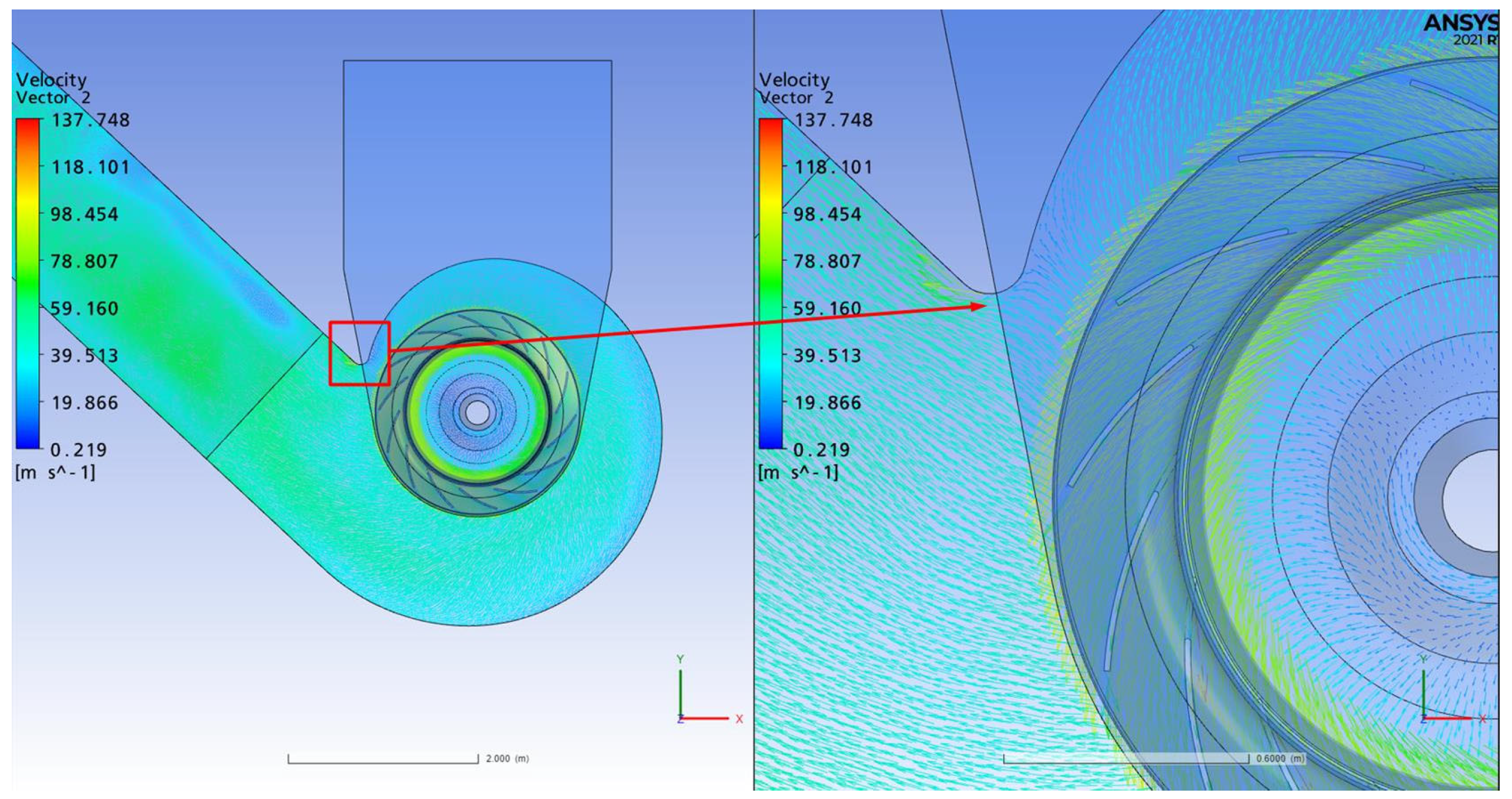
Figure 8 presents a detailed visualization of the velocity vector distribution in the XY plane of the narrow casing configuration. The velocity color contours show a clear stratification, where low-speed peripheral regions are indicated by blue and green shades (approximately 0–20 m/s), whereas higher velocity zones in proximity to the impeller outlet are visualized through yellow to red gradients (approaching 80–130 m/s). A prominent observation is the oblique impact of the high-speed flow on the splitter plate, where the vectors do not align centrally but impinge asymmetrically from the sides. This misalignment gives rise to localized separation bubbles along the inner wall of the outlet channel, a phenomenon that exacerbates static pressure loss and secondary flow instabilities [48]. These separation zones are particularly detrimental in centrifugal fan systems, as they reduce aerodynamic efficiency and lead to energy wastage [49]. Moreover, the vortex stretching observable in the outlet channel suggests enhanced turbulence intensity due to sharp directional changes, especially where the flow redirects after interacting with the volute geometry. Similar behavior has been reported in studies examining volute-induced asymmetries in single-inlet centrifugal fans, where flow misalignment led to reduced pressure recovery and intensified unsteadiness in the discharge region [50]. The narrow casing’s geometric constraint appears to constrain the natural swirl development, limiting the impeller’s ability to convert dynamic pressure into static pressure efficiently. Such limitations were also identified by Cai et al. [42], who emphasized the critical role of volute design in ensuring uniform pressure distribution and reducing performance degradation under constrained geometries. Furthermore, the clear discrepancy between the inflow direction and the volute’s curvature suggests a lack of flow guidance at the transition zone, leading to localized recirculation zones that not only decrease performance but may also increase structural fatigue risks due to fluctuating pressure loads [51]. Figure 7 not only visualizes the aerodynamic inefficiencies but also underlines a core design flaw: the splitter plate receives skewed, high-momentum flow jets, which cause uneven loading and compromise downstream flow uniformity. This reinforces the necessity for a re-engineered volute and splitter interface, possibly incorporating a vortex control element or modified blade trailing geometry to mitigate separation [44].
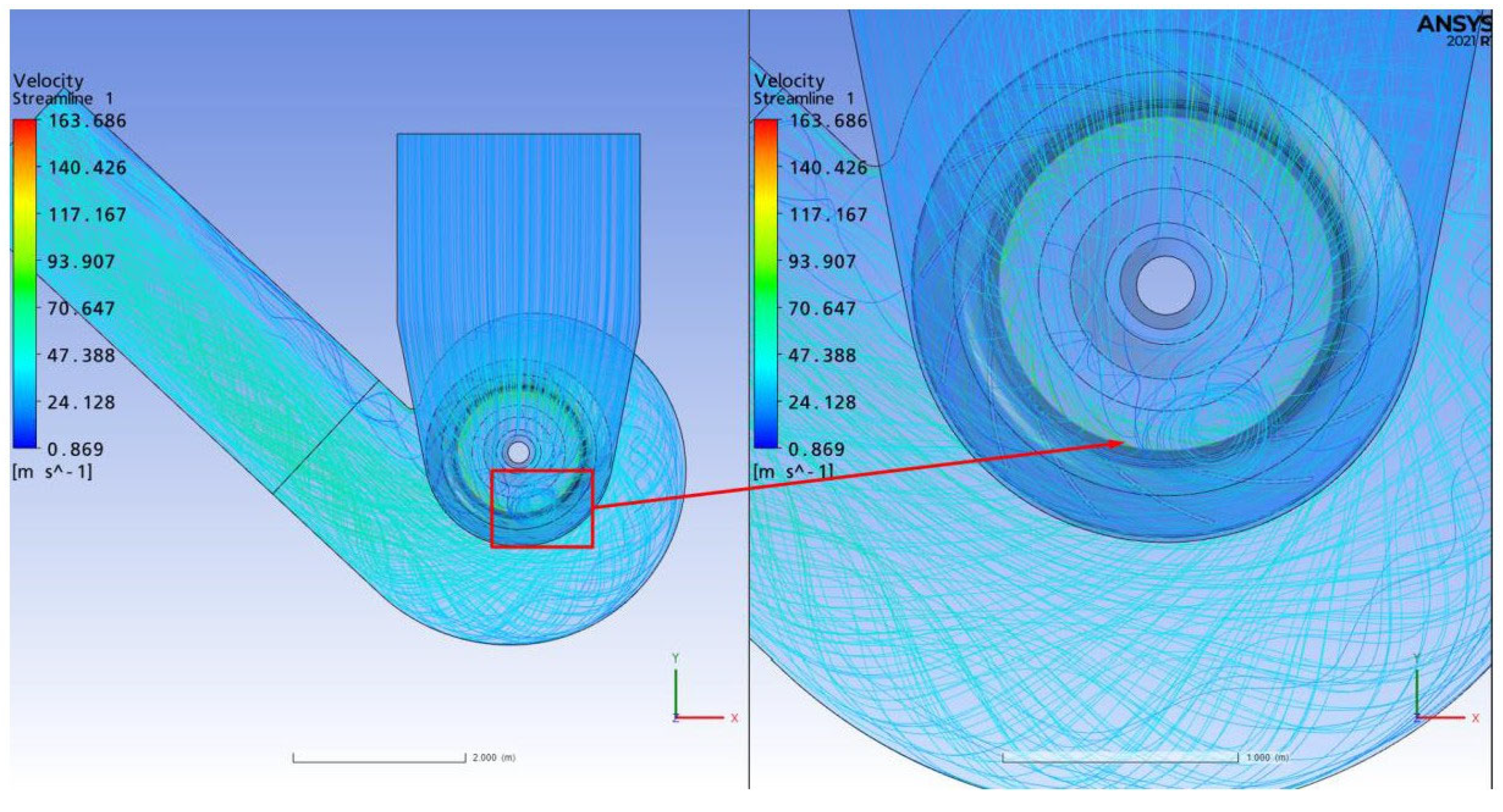
Figure 9 presents the three-dimensional streamlines of the airflow in the XY plane for the narrow-body fan configuration, providing a detailed view of the vortex structure in the inlet pocket region. The color scale reveals low-velocity regions in the range of approximately 0.8–25 m/s, represented by blue to green hues, and high-velocity regions ranging from 47 to 163 m/s, indicated by yellow to red tones. A pronounced vortex structure is distinctly visible at the lower region of the inlet pocket, characterized by a swirling motion of the incoming flow before it reaches the impeller blades. This vortex is primarily caused by geometric confinement and abrupt directional changes, which induce flow separation and energy dissipation. This recirculating zone not only delays the progression of the suction flow but also introduces non-uniform velocity profiles across the impeller inlet, leading to pressure instabilities and an uneven loading distribution on the rotor blades. Such conditions are known to result in performance degradation and increased mechanical stress on the impeller, which may elevate the risk of fatigue-induced failure over prolonged operational cycles [52]. Furthermore, the proximity of the vortex core to the impeller accentuates the asymmetric inflow conditions, adversely affecting the fan’s aerodynamic performance and reducing overall static pressure rise [53]. The high-resolution CFD model used in this study (163.6 m/s maximum velocity) allows the accurate capture of this vortex structure, validating the necessity of using fine near-wall resolution (y+ ≈ 2.8) and transient analysis for identifying these dynamic flow phenomena. Comparable studies, such as those by Liu et al. [54] and Ottersten et al. [55], have emphasized the detrimental effect of large-scale inlet vortices on fan efficiency and noise levels. Moreover, the presence of such a vortex, rotating in the opposite direction to the impeller, contributes to secondary flows that amplify turbulence intensity and may lead to aerodynamic noise emission, a concern increasingly addressed in industrial fan design frameworks. The observed vortex structure in the inlet pocket of the narrow casing geometry presents a critical aerodynamic defect, reinforcing the need for geometry modifications such as inlet cone smoothing, vortex breakers, or widened cross-sections, which have been shown to significantly mitigate these flow irregularities in recent optimization-focused research.
Analysis results indicated that the narrow casing design increased pressure loss due to a large shaft-induced vortex in the inlet pocket, creating irregularities in the flow direction towards the impeller. These vortices were identified as the primary factors that increased the fan’s energy consumption and reduced total pressure generation. In light of these findings, design revisions were made, including a casing width of 2520 mm, an outlet width of 1808 mm to 1858 mm, and the installation of a vortex breaker in the inlet pocket.
Figure 10 presents the velocity vectors in the YZ plane for the revised industrial fan casing configuration. According to the updated velocity scale extracted from the CFD results, the flow velocities range from approximately 0.66 m/s to 131.7 m/s, with blue and green shades (0.66–56.8 m/s) denoting the low-velocity zones predominantly located in the lower inlet region. In contrast, higher flow velocities (up to 131.7 m/s), represented in yellow to red, are concentrated near the impeller periphery. Compared to the narrow-body design, the enlarged casing geometry in this revised configuration facilitates a more gradual acceleration and a streamlined flow trajectory into the rotor region. The expansion of the casing’s inlet section minimizes abrupt contractions, thereby reducing velocity gradients and potential recirculation pockets. This effect is particularly visible in the rotor’s root region, where the previous case exhibited intense flow bending and separation. Now, the velocity vectors maintain alignment and coherence through the impeller, supporting a more uniform pressure build-up across the blade span. Furthermore, the increased slope of the shaft cone appears to play a crucial role in smoothing the inlet flow angle and mitigating secondary flow effects at the blade hub. These improvements are essential, as flow uniformity at the impeller inlet is directly linked to pressure rise efficiency and blade loading balance [56,57].
The observed elimination of major separation zones in this configuration not only contributes to improved aerodynamic efficiency but also reduces unsteady aerodynamic loading and potential vibration-induced fatigue in rotor components. Recent investigations on similar centrifugal fan optimizations also underscore that smooth, tangential inlet flow and geometric tapering substantially enhance fan operational stability [58,59].
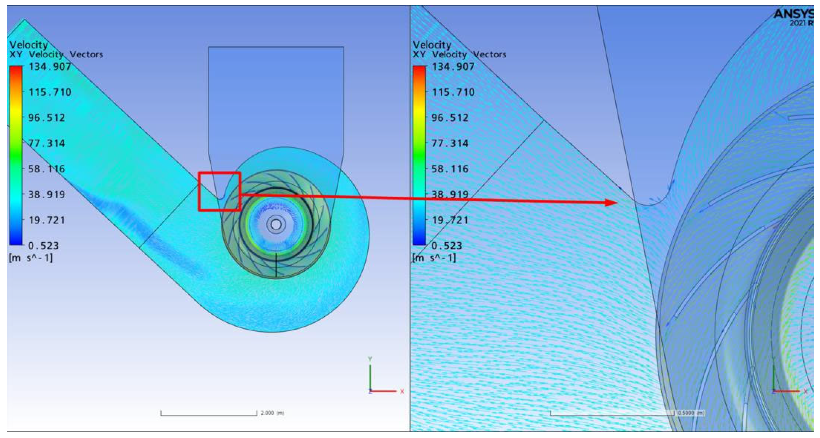
Figure 11 presents the velocity vectors within the XY plane of the revised casing configuration, revealing a substantially improved flow structure compared to the narrow-body design. The updated velocity color scale demonstrates that blue regions (~0.5–10 m/s) are concentrated near the casing wall, while green to yellow tones (~38–77 m/s) dominate the primary flow pathway. The highest velocity observed reaches approximately 134.9 m/s, particularly near the impeller outlet, as indicated by the red zones in the flow channel. These values confirm a significant acceleration of the flow while maintaining directional stability. One of the key improvements lies in the outlet geometry modification, where the outlet channel width was increased from 1808 mm to 1858 mm. This geometrical change was implemented to mitigate the asymmetric flow impingement observed in the earlier design, allowing the flow to strike the splitter plate (parting tongue) centrally and symmetrically. The result is a markedly more homogeneous velocity distribution across the outlet, as evidenced by the aligned vectors in the figure. The balanced interaction between the flow and the splitter plate reduces separation zones and suppresses the formation of recirculation regions that were previously responsible for turbulence and static pressure losses. Such improvements in outlet aerodynamics directly enhance the total pressure recovery and fan efficiency, aligning with findings from recent CFD-based fan optimization studies [60,61,62]. Furthermore, the observed flow behavior suggests that the revised casing design effectively redirects high-speed flow away from the volute walls, reducing shear-induced turbulence. This redirection and symmetric discharge condition are known to be critical for improving the stability and service life of industrial fans [63]. The updated outlet channel width and associated geometric adjustments lead to a more orderly and energy-efficient flow structure. The design revisions address prior deficiencies in splitter interaction and outlet channel symmetry, thereby enhancing pressure recovery, reducing turbulence intensity, and improving operational performance.
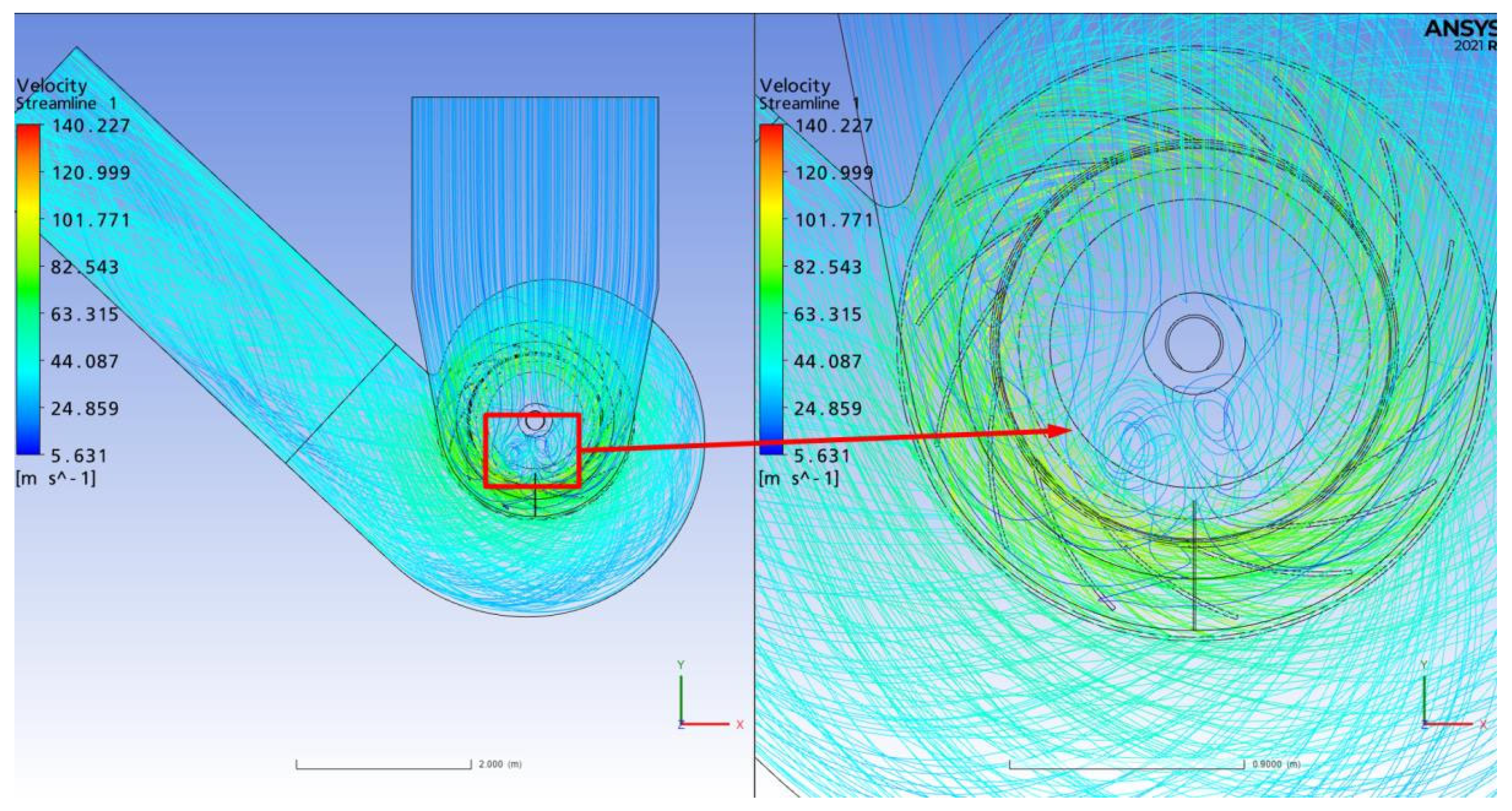
Figure 12 depicts the three-dimensional streamlines of the flow in the wide-body fan configuration, emphasizing the effect of the vortex breaker positioned in the inlet pocket. According to the updated velocity scale, the flow velocities range from approximately 5.6 m/s in the low-speed regions (shown in blue and green tones) to about 140.2 m/s in the high-velocity core near the impeller outlet (displayed in yellow-red). This broader velocity distribution reflects a more energetic but better-organized flow field compared with the narrow-body case. The integration of the vortex breaker substantially alters the internal aerodynamics of the inlet pocket, suppressing the large coherent vortex that dominated the narrow-body configuration and replacing it with two smaller, symmetric counter-rotating vortices. This dual-vortex system diffuses the swirl intensity, creating a more balanced distribution of momentum and kinetic energy before the flow reaches the impeller. As a result, the airflow follows a steadier, tangential trajectory toward the impeller eye, minimizing separation and stabilizing the pressure field across the inlet cone. Similar findings have been reported in industrial fan studies where flow-control devices reduced recirculation and turbulence intensity by more than 20% [64].
This geometric improvement yields three major aerodynamic benefits. A reduction in total pressure loss in the inlet cone due to the suppression of backflow zones. A more uniform velocity distribution at the impeller face, ensuring balanced aerodynamic loading on the blades. Enhanced overall fan efficiency, as the energy of the inlet flow is converted more effectively into useful pressure rise. The observed flow organization confirms that the wide-body design improves not only efficiency but also operational stability and mechanical reliability, since the balanced inlet conditions lower vibration and noise levels [65]. The analysis in Figure 12 thus illustrates how strategically positioned flow-control elements, such as vortex breakers, can transform the internal aerodynamics of centrifugal fans, aligning with the broader trend of CFD-driven geometric optimization in heavy-duty process ventilation [66,67].
Wide-body analyses detailed the effects of the design revisions on fan flow performance. The changes, particularly the increase in the outlet channel width from 1808 mm to 1858 mm, optimized the point at which the flow impinges on the fan blade. As shown in Figure 10, the velocity vectors are directed symmetrically and centrally towards the fan blade, preventing the asymmetric separation zones observed in the previous narrow-body design. This reduces static pressure losses and ensures linear direction of the outlet flow. The vortex breaker added to the inlet pocket (Figure 11) controls the large, energy-wasting vortex, which is evident in the narrow-body design, and divides it into two smaller, more regular vortices. This structure ensures a homogeneous distribution of flow energy within the inlet cone, allowing the flow to reach the impeller inlet with a smooth and balanced velocity profile. The flow filaments in the analysis indicate that this vortex breaker effect significantly reduces turbulence levels in the fan intake line and reduces total pressure loss. Furthermore, the velocity vectors obtained in the YZ plane (Figure 9) demonstrate that the optimization of the shaft cone slope minimizes flow separation in the rotor root region. The high velocity gradients (~30–40 m/s) and directional changes observed in the inlet region of the previous narrow-body design have been significantly reduced, and the flow lines exhibit a smoother velocity increase (~5–134 m/s) from inlet to outlet. This homogeneous velocity distribution improves load balance around the rotor blades, reducing potential vibration risks and increasing energy efficiency. Performance results from numerical analyses also confirm that the design objectives have been met. In the revised wide-body design, according to CFD analysis results, the fan can produce 2200 Pa static pressure and 2580 Pa total pressure at a flow rate of 601,241 m3/h, and shaft power is calculated at 520 kW. These values, when compared to the desired design target of 2156 Pa static pressure and 2447 Pa total pressure, show that the targets are met with a safe margin and 83% efficiency level can be maintained.
Consequently, the geometric modifications successfully managed flow separation and vortex formation within the inlet pocket, thereby establishing a more stable flow field between the impeller inlet and outlet. This ensures the smooth alignment of the separation tongue in the outlet channel and enhances fan performance in accordance with specified design objectives. These enhancements provide engineering advantages that are expected to beneficially influence both energy consumption and overall system efficiency.

3.3. ID Fan Analysis Results

In the ID fan analysis, a time-dependent solution of the rotor-stator interactions and the complex flow structures around the impeller was performed at a volumetric flow rate of 441,643 m3/h. The flow filaments and velocity vectors indicate that a smooth flow is maintained within the fan and that no large separations occur between the impeller inlet and outlet regions.
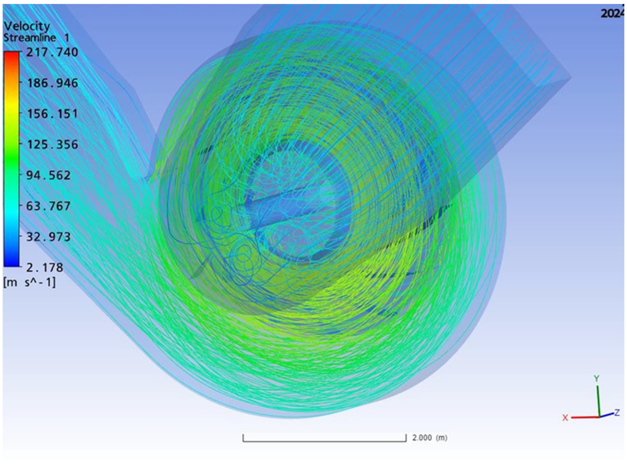
Figure 13 presents the three-dimensional flow streamlines obtained in the time-dependent solution of the ID fan model. The image details the rotational flow structure generated by the rotor operating at 990 rpm, with streamlines clearly illustrating the directional motion from the intake cone toward the impeller blades. These flow streamlines exhibit a smooth spiral trajectory, progressing continuously from the fan inlet region along the blade surfaces and extending through to the outlet channel. According to the updated color scale in the figure, velocity magnitudes in the intake region are observed within the range of 2.1–32.9 m/s, while the rotor region and the impeller blade exit reach significantly higher velocities of up to 217.7 m/s. The appearance of red and yellow tones around the rotor indicates high-energy zones, which confirms the effective transfer of rotational kinetic energy to the flow. This outcome signifies that the design has succeeded in minimizing turbulence and separation effects while promoting a stable, coherent velocity field. The largely uniform and parallel structure of the flow streamlines reinforces the fan’s capability to meet system pressure requirements efficiently. As validated by recent studies [62,66], such uniform streamline behavior in centrifugal fan systems directly correlates with enhanced aerodynamic performance and reduced energy dissipation. Moreover, the smooth progression of these streamlines through the blade passage supports the theoretical prediction of increased static pressure rise, in line with the operational goals of the wide-body fan design. The suppression of recirculation zones and the conservation of angular momentum within the impeller confirms the effectiveness of the applied design revisions, particularly regarding intake geometry and flow alignment.
Figure 14 illustrates the velocity vectors and magnitude distribution of the fan flow within the Y–Z plane, emphasizing the aerodynamic performance characteristics of the wide-body configuration. According to the updated color scale shown in the figure, blue and green hues (~0.5–50 m/s) denote the low-velocity regions concentrated around the inlet cone and upstream diffuser surfaces, whereas the velocity values increase to orange and red hues (~130–180 m/s) as they approach the rotor and blade exit area. This gradient indicates a significant pressure energy conversion process taking place across the impeller domain. The funnel-shaped orientation of the velocity vectors at the inlet, smoothly directed toward the impeller, confirms that the inlet geometry has been optimized to suppress flow separation and minimize recirculation zones. As the rotor rotates, the flow streamlines bend and accelerate, forming a well-defined spiral structure, a characteristic of controlled swirl generation that is essential for total pressure build-up in centrifugal fans [68]. The uniform directionality and magnitude of the flow streamlines in this section also confirm that the rotor–stator interaction has been accurately modeled using transient (time-dependent) CFD analysis, which is necessary to capture the unsteady nature of flow separation and tip leakage effects. The smooth velocity contours and reduced turbulence intensity near the stator sidewalls indicate a highly efficient energy transfer process, validating the integrity of the design improvements made in the wide-body revision. This behavior is consistent with design guidelines presented in recent CFD-based fan performance optimization studies, which emphasize the importance of minimizing radial velocity deviation and maximizing tangential velocity near the rotor tips to enhance aerodynamic stability and reduce vibration-induced failure risks [69,70].
The CFD results reveal that the rotor’s 990 rpm rotation effectively captures the complex rotational and turbulent flow structures inside the fan. As illustrated in Figure 11, the flow streamlines form a smooth spiral starting from the inlet cone and wrapping around the rotor, indicating controlled high-speed vortex generation in the rotor–stator transition region. According to the updated color scale, velocity magnitudes increase from ~2–20 m/s at the inlet to over 180 m/s near the rotor, confirming efficient energy transfer and swirl formation. Figure 12 further supports this by showing that the velocity vectors follow a uniform path toward the outlet channel. This directional coherence indicates that the rotor imparts a well-balanced velocity profile to the incoming flow, minimizing turbulence and mechanical vibration risks. The gradual and stable acceleration across the domain confirms low flow separation, demonstrating that the design meets aerodynamic performance expectations. These findings validate that the wide-body fan geometry has been successfully optimized for minimizing pressure loss and achieving high-efficiency flow delivery under industrial operating conditions. This reduces the total pressure loss in the fan suction line, increasing the fan’s system efficiency. Performance results obtained from the numerical analyses support the successful achievement of the design objectives. The designed flow rate for the ID fan is 441,643 m3/h, and analyses yielded approximately 8653 Pa static pressure and 9203 Pa total pressure at this flow rate. Shaft power was calculated at 1356 kW, and total efficiency was determined to be 83.24%. These values demonstrate that the fan can provide the required pressure generation against system resistance while maintaining the targeted 83% efficiency level and meeting the design criteria for energy efficiency.
Consequently, CFD analyses enabled the successful modeling of the complex turbulent structures and rotational flow characteristics in the rotor rotational flow field. They confirmed that the fan design was optimized for both flow separation and pressure loss, ensuring performance that met the cement plant’s process requirements.

3.4. Field Tests and Comparative Performance Analysis

Following the CFD-based design and optimization process, the newly produced fans (ID Fan and Flour Oven Bag Filter Fan) were tested under field conditions. The tests were conducted in accordance with the ISO 5802 standard [71], and the measurement results were within the tolerance criteria of DIN 24,166 Cl.2 [72]. To make the new fan tests (8 May 2025) comparable to the old fan tests (15 November 2023), the measured values were corrected to the same speed and temperature conditions using fan laws.

3.4.1. ID Fan Performance Comparison

Table 5 clearly demonstrates the effects of CFD-based design changes on the ID fan. Firstly, the volumetric flow rate was maintained at 401,494 m3/h in both cases. This demonstrates that the aerodynamic improvements met the system requirements without changing capacity. Total pressure was measured at 656.0 mm3/h in the new design, compared to 742.7 mm3/h in the old design, resulting in an approximately 11.7% reduction. This reduction is due to the elimination of flow separation and a smoother inlet flow, resulting in less pressure required to achieve the same flow rate. The most significant improvement is seen in shaft power. The shaft power of the old fan, 1204.9 kW, has decreased to 889.0 kW in the new design, representing a 26.2% reduction. This difference translates to an energy saving of approximately 2527 MWh based on an annual operating time of 8000 h. Total efficiency increased from 67.4% to 80.6%, representing an absolute increase of 13.2 percentage points and a relative improvement of 19.6%. When all this data is evaluated together, it can be concluded that the CFD-supported design changes are effective under field conditions, achieving the same capacity with lower pressure and energy consumption, while also achieving a significant efficiency increase. These improvements reduce operating costs and contribute significantly to energy efficiency and environmental sustainability. Measurements corrected for 900 rpm and an inlet temperature of approximately 297 °C are provided below.
The new design reduced shaft power by 26.2% and increased total efficiency by 19.6% at the same flow rate. This demonstrates that the effects of eliminating flow separation and homogenizing the inlet flow predicted by CFD analyses have been confirmed in the field.

3.4.2. White Oven Fan (19494) Performance Comparison

Table 6 demonstrates the effects of CFD-based design revisions on the Flour Kiln Bag Filter Fan. Firstly, the volumetric flow rate was measured as 331,880 m3/h in the new design, compared to 388,681 m3/h in the old design, representing a 14.6% reduction. This decrease in flow rate could be due to differences in operating conditions or adjustments made to adapt to system requirements. However, the constant pressure (102.4 mm SS in both cases) indicates that the new design operates at the required pressure. In terms of shaft power, the old fan’s 162.9 kW power output has decreased to 106.8 kW in the new design, representing a 34.4% reduction. This translates to lower energy consumption when operating at the same pressure. Considering an annual operating time of 8000 h, this difference translates to energy savings of approximately 449 MWh/year, significantly reducing operating costs. Overall efficiency increased from 66.5% for the old fan to 86.7% for the new design, representing an absolute increase of 20.2 percentage points and a relative increase of 30.4%. This represents a significant efficiency gain achieved by improving inlet flow, reducing flow separation, and minimizing aerodynamic losses. Overall, these results demonstrate that the CFD-assisted design optimization significantly reduces energy consumption and significantly increases efficiency by maintaining system pressure despite the reduced flow rate. This provides a sustainable solution in terms of both energy efficiency and operating economics. Measurements corrected for 640 rpm and an inlet temperature of approximately 155 °C are presented below.
Despite operating at a 14.6% lower flow rate, the new filter fan achieved a 34.4% reduction in shaft power and a 30.4% increase in overall efficiency. This result demonstrates that design improvements can significantly increase energy efficiency even under low load conditions.
For both fan types, CFD-driven design changes resulted in significant reductions in energy consumption and significant increases in efficiency by eliminating flow separation, symmetrical inlet flow, and reducing aerodynamic losses. Shaft power reductions of 315.9 kW for the ID Fan and 56.1 kW for the Filter Fan offer significant electricity savings and carbon emission reduction potential when scaled to annual operating hours. These results strongly support the economic and environmental benefits of CFD-based design optimization in heavy industry applications.

4. Conclusions

In this investigation, design optimization and computational fluid dynamics (CFD) analyses were performed for two distinct types of industrial fans utilized at the Yurt Cement facility. One fan was engineered for a flour mill filter and underwent a revised design process due to the necessity for casing narrowing. The other, an ID fan for the clinker kiln, was intended to validate full-scale performance under conditions of high volumetric flow, including rotor-stator interactions.
Analyses of the flour mill fan revealed that the casing was narrowed by a total of 269 mm on both sides, resulting in large-scale vortex formations and flow separation in the inlet pocket. Computational Fluid Dynamics (CFD) results demonstrated that the narrow casing design caused irregular velocity distribution within the inlet cone, led to asymmetric impingement of the flow on the separation tongue at an inappropriate location, and induced substantial static pressure losses in the outlet channel. Consequently, the total pressure rise was diminished, thereby reducing fan efficiency below the targeted level. Design modifications encompassed increasing the casing width, optimizing the outlet channel dimensions, and incorporating a vortex breaker within the inlet pocket. The revised design ensures a streamlined flow path from the inlet to the impeller, accurately centers the impact point on the separation fin, and decomposes the vortex structures within the inlet pocket into two smaller, more uniform vortices. Numerical analysis outcomes confirmed that the modifications to the wide-body design enabled the fan to surpass the originally specified static pressure of 2156 Pa and total pressure of 2447 Pa (achieving 2200 Pa and 2580 Pa, respectively) at a flow rate of 601,241 m3/h, while maintaining an efficiency level of 83%.
In the design of the ID fan, the swirling flow patterns, turbulent regions, and transitions at the rotor-stator interface occurring at a rotor speed of 990 rpm were modeled over time. Flow filaments and velocity vectors indicated that the flow directed from the inlet cone to the impeller progressed uniformly without separation or large-scale vortex structures and entered the rotor blades with a smooth velocity profile. The velocity distribution in the Y-Z and Y-X planes exhibited a gradual and symmetrical increase, reaching 40–50 m/s at the rotor exit, thereby demonstrating that the total pressure increase was adequate to counteract the system resistance. Numerical analysis results revealed that, at a flow rate of 441,643 m3/h, static pressure values of approximately 8653 Pa and total pressure of 9203 Pa were achieved, and the fan was estimated to operate at an efficiency level of 83.24%.
These CFD analyses conducted on both fan types facilitated a dependable verification of whether the design objectives were achieved and enabled the formulation of revision recommendations through an engineering-based methodology. The findings illustrate that geometry optimization is essential to prevent flow separation and vortex formations that may occur within the inlet pocket. Ensuring a smooth flow directed towards the outlet channel’s separation tongue will mitigate static pressure losses. Detailed modeling of rotor-stator interactions using a time-dependent solution enhances overall design quality.
This study underscores the significance of CFD-based design methodologies in enhancing the performance of fan systems within energy-intensive industries such as the cement sector. Future research endeavors, including comparative analyses of various turbulence models in fan design, investigations into compressibility effects, and comprehensive validation studies utilizing data collected under real-world conditions, will further advance engineering solutions in this domain. Field test results have validated the CFD-based design improvements for both the ID and Filter fans under comparable operational conditions, demonstrating notable operational advantages. For the ID fan, the redesign achieved a 26.2% reduction in shaft power and a 19.6% increase in efficiency, translating to an annual energy savings of approximately 2527 MWh and a reduction of about 1011 tCO2 emissions, based on 8000 operating hours per year. Regarding the Filter fan, shaft power decreased by 34.4% with an efficiency gain of 30.4%, leading to approximately 449 MWh of energy savings annually and a reduction of 180 tCO2 emissions per year. These empirical gains confirm that vortex suppression, enhanced inlet flow uniformity, and optimized geometry directly improve operational efficiency. The combined annual savings from both fans amount to 2976 MWh and 1190 tCO2. The concordance between simulation data and field measurements reinforces the reliability of CFD-driven aerodynamic optimization, emphasizing its dual benefit of improving mechanical performance and significantly contributing to cost reduction and sustainability objectives within heavy industry.

Author Contributions

Conceptualization, F.D. and S.Ö.; methodology, F.D. and U.D.; software, U.D.; validation, F.D., K.K. and M.Ş.E.; formal analysis, F.D.; investigation, F.D. and H.O.; resources, K.K. and H.O.; data curation, U.D.; writing—original draft preparation, F.D.; writing—review and editing, U.D. and S.Ö.; visualization, F.D. and U.D.; supervision, S.Ö.; project administration, F.D.; funding acquisition, H.O. All authors have read and agreed to the published version of the manuscript.

Funding

This research received no external funding.

Institutional Review Board Statement

Not applicable.

Informed Consent Statement

Not applicable.

Data Availability Statement

The CFD models, simulation datasets, and field measurement records supporting the findings of this study are available from Alfer Engineering, upon reasonable request. All raw data are stored in the project archive of Yurt Cement Inc. for collaborative research use.

Acknowledgments

The authors gratefully acknowledge the technical assistance provided by Yurt Cement Inc. during on-site fan performance measurements and Alfer Engineering for their contribution to the prototype design and CFD validation.

Conflicts of Interest

Author Kadir Körükçü is employed by Alfer Engineering company. Author Hamza Oduncu and Mehmet Şirin Eken are employed by Yurt Cement Inc. The remaining authors declare that the research was conducted in the absence of any commercial or financial relationships that could be construed as a potential conflict of interest.

References

  1. Lakshminarayana, B. Fluid Dynamics and Heat Transfer of Turbomachinery; John Wiley & Sons: Hoboken, NJ, USA, 2007; pp. 1–809. [Google Scholar] [CrossRef]
  2. Moczko, P.; Odyjas, P.; Pietrusiak, D.; Więckowski, J.; Scholz, P.; Dix, M.; Osiecki, T.; Timmel, T.; Kroll, L. Enhancing efficiency of industrial centrifugal fans using blade adjustment mechanism. Energies 2022, 15, 893. [Google Scholar] [CrossRef]
  3. Ray, A.L.; Couse, D. Cement plant fan efficiency upgrades. IEEE Trans. Ind. Appl. 2017, 53, 1562–1568. [Google Scholar] [CrossRef]
  4. Fortini, A.; Suman, A.; Zanini, N. An experimental and numerical study of the solid particle erosion damage in an industrial cement large-sized fan. Eng. Fail. Anal. 2023, 146, 107058. [Google Scholar] [CrossRef]
  5. Choudhary, P.K.; Dubey, S.P. Energy efficient operation of induction motor drives: Economic and environmental analysis in cement manufacturing. Environ. Prog. Sustain. Energy 2019, 38, 672–679. [Google Scholar] [CrossRef]
  6. Cantini, A.; Leoni, L.; De Carlo, F.; Salvio, M.; Martini, C.; Martini, F. Technological energy efficiency improvements in cement industries. Sustainability 2021, 13, 3810. [Google Scholar] [CrossRef]
  7. Corsini, A.; Delibra, G.; Sheard, A.G. A critical review of computational methods and their application in industrial fan design. ISRN Mech. Eng. 2013, 2013, 625175. [Google Scholar] [CrossRef]
  8. Barbhuiya, S.; Kanavaris, F.; Das, B.B.; Idrees, M. Decarbonising cement and concrete production: Strategies, challenges and pathways for sustainable development. J. Build. Eng. 2024, 86, 108861. [Google Scholar] [CrossRef]
  9. Sahoo, N.; Kumar, A. Samsher Review on energy conservation and emission reduction approaches for cement industry. Environ. Dev. 2022, 44, 100767. [Google Scholar] [CrossRef]
  10. Catrini, P.; La Villetta, M.; Kumar, D.M.; Morale, M.; Piacentino, A. Analysis of the operation of air-cooled chillers with variable-speed fans for advanced energy-saving-oriented control strategies. Appl. Energy 2024, 367, 123393. [Google Scholar] [CrossRef]
  11. Yu, J.; Fu, W.; Wang, W.; Sun, P. Non-Axisymmetric Design and Flow Field Analysis of Boundary Layer Ingesting Fans. Aerosp. Sci. Technol. 2023, 140, 108429. [Google Scholar] [CrossRef]
  12. Zanoli, S.M.; Pepe, C.; Astolfi, G. Advanced Process Control for Clinker Rotary Kiln and Grate Cooler. Sensors 2023, 23, 2805. [Google Scholar] [CrossRef]
  13. Amarasinghe, W.S.; Husum, I.; Tokheim, L.A. Waste Heat Availability in the Raw Meal Department of a Cement Plant. Case Stud. Therm. Eng. 2018, 11, 1–14. [Google Scholar] [CrossRef]
  14. Tang, G.; Liang, F.; Ma, Z.; Wang, Z.; Chen, J.; Zhu, Y.; Jin, M. Investigation of Cold Tube Structure on Flow Characteristics and Energy Separation in Vortex Tube Based on Numerical and Thermodynamic Analyses. Appl. Therm. Eng. 2024, 254, 123893. [Google Scholar] [CrossRef]
  15. Wang, J.; Kruyt, N.P. Design for High Efficiency of Low-Pressure Axial Fans with Small Hub-to-Tip Diameter Ratio by the Vortex Distribution Method. J. Fluids Eng. 2022, 144, 081201. [Google Scholar] [CrossRef]
  16. Maghsoudi, I.; Vaziry, M.A.; Mahmoodi, M. Experimental Investigation of Flow and Distortion Mitigation by Mechanical Vortex Generators in a Coupled Serpentine Inlet-Turbofan Engine System. Chin. J. Aeronaut. 2020, 33, 1375–1391. [Google Scholar] [CrossRef]
  17. Ryu, S.Y.; Cheong, C.; Kim, J.W.; Park, B.I. Analysis of Aerodynamic and Aeroacoustic Performances of Axial Flow Fans with Variable Winglet Curvature in Chordwise Direction. Results Eng. 2024, 21, 101857. [Google Scholar] [CrossRef]
  18. De Keulenaer, H. Energy Efficient Motor Driven Systems. Energy Environ. 2004, 15, 873–905. [Google Scholar] [CrossRef]
  19. Afkhami, B.; Akbarian, B.; Beheshti, A.N.; Kakaee, A.H.; Shabani, B. Energy Consumption Assessment in a Cement Production Plant. Sustain. Energy Technol. Assess. 2015, 10, 84–89. [Google Scholar] [CrossRef]
  20. Bae, Y.S.; Islam, M.D.; Choi, Y.D.; Kang, H.J.; Tae, S.J.; Kim, H.H. Back-Turn Approach for Optimal Operation of Booster Pump Systems. J. Appl. Fluid Mech. 2025, 18, 2202–2211. [Google Scholar] [CrossRef]
  21. Rakibuzzaman, M.; Kim, H.H.; Kim, K.W.; Suh, S.H.; Bae, Y.S. A Study on Booster Pump System with Flow Sensor for Individual Flow Control Method. J. Appl. Fluid Mech. 2022, 15, 889–900. [Google Scholar] [CrossRef]
  22. Van Rooij, M.; Medd, A. Reformulation of a Three-Dimensional Inverse Design Method for Application in a High-Fidelity CFD Environment. In Proceedings of the ASME Turbo Expo 2012: Turbine Technical Conference and Exposition, Copenhagen, Denmark, 11–15 June 2012; Volume 8, pp. 2395–2403. [Google Scholar] [CrossRef]
  23. Zhang, J.; Zangeneh, M. Multi-Point, Multi-Objective Optimisation of Centrifugal Fans by 3D Inverse Design Method. Int. J. Turbomach. Propuls. Power 2023, 8, 8. [Google Scholar] [CrossRef]
  24. Watanabe, H.; Zangeneh, M. Design of the Blade Geometry of Swept Transonic Fans by 3D Inverse Design. In Proceedings of the ASME Turbo Expo 2003, Collocated with the 2003 International Joint Power Generation Conference, Atlanta, GA, USA, 16–19 June 2003; Volume 6A, pp. 603–612. [Google Scholar] [CrossRef]
  25. Namazizadeh, M.; Gevari, M.T.; Mojaddam, M.; Vajdi, M. Optimization of the Splitter Blade Configuration and Geometry of a Centrifugal Pump Impeller Using Design of Experiment. J. Appl. Fluid Mech. 2020, 13, 89–101. [Google Scholar] [CrossRef]
  26. Xie, X.; Li, Z.; Zhu, B.; Wang, H.; Zhang, W. Multi-Objective Optimization Design of a Centrifugal Impeller by Positioning Splitters Using GMDH, NSGA-III and Entropy Weight-TOPSIS. J. Mech. Sci. Technol. 2021, 35, 2021–2034. [Google Scholar] [CrossRef]
  27. Heo, M.W.; Kim, J.H.; Cha, K.H.; Kim, K.Y. Parametric Study on Aerodynamic Performance of a Centrifugal Fan with Additionally Installed Splitter Blades. In Proceedings of the ASME 2013 Fluids Engineering Division Summer Meeting, Incline Village, NV, USA, 7–11 July 2013; Volume 1B. [Google Scholar] [CrossRef]
  28. Rivera, E.D.J.; Besem-Cordova, F.; Bonaccorsi, J.C. Optimization of a High Pressure Industrial Fan. In Proceedings of the ASME Turbo Expo 2021: Turbomachinery Technical Conference and Exposition, Virtual, Online, 7–11 June 2021; Volume 1. [Google Scholar] [CrossRef]
  29. Zhang, J.; Chen, Y.; Jin, L.; Chen, D. Performance and Flow Evolution of Windmilling Utilizing a Combination of Semi-Empirical Speed and CFD Models during Mode Transition of the Wide-Chord Fan. Aerosp. Sci. Technol. 2022, 123, 107468. [Google Scholar] [CrossRef]
  30. Zelenský, P.; Barták, M.; Zavrel, V.; Zmrhal, V.; Krupa, R. Numerical Analysis of Air Flow in a Modular Fan Unit Using CFD Simulation. E3S Web Conf. 2019, 111, 01008. [Google Scholar] [CrossRef]
  31. Darmanto, P.S.; Syahlan, A.; Wibowo, M.A. Redesign and Implementation of Big Fan Impellers for Enhancing Its Efficiency. Int. J. Fluid Mach. Syst. 2022, 15, 246–255. [Google Scholar] [CrossRef]
  32. McKervey, G.W.; Perry, B. Fan Applications in the Cement Industry. In Proceedings of the 35th IEEE Cement Industry Technical Conference, Toronto, ON, Canada, 23–27 May 1993; pp. 467–476. [Google Scholar] [CrossRef]
  33. Szpicer, A.; Bińkowska, W.; Stelmasiak, A.; Zalewska, M.; Wojtasik-Kalinowska, I.; Piwowarski, K.; Piepiórka-Stepuk, J.; Półtorak, A. Computational Fluid Dynamics Simulation of Thermal Processes in Food Technology and Their Applications in the Food Industry. Appl. Sci. 2025, 15, 424. [Google Scholar] [CrossRef]
  34. Oberkampf, W.L.; Trucano, T.G. Verification and Validation in Computational Fluid Dynamics. Prog. Aerosp. Sci. 2002, 38, 209–272. [Google Scholar] [CrossRef]
  35. Ahmad, R.; Kamaruddin, S. An Overview of Time-Based and Condition-Based Maintenance in Industrial Application. Comput. Ind. Eng. 2012, 63, 135–149. [Google Scholar] [CrossRef]
  36. da Silva, E.R.; Kyprianidis, K.G.; Camacho, R.G.R.; Säterskog, M.; Angulo, T.M.A. Preliminary Design, Optimization and CFD Analysis of an Organic Rankine Cycle Radial Turbine Rotor. Appl. Therm. Eng. 2021, 195, 117103. [Google Scholar] [CrossRef]
  37. Liu, X.; Dang, Q.; Xi, G. Performance Improvement of Centrifugal Fan by Using CFD. Eng. Appl. Comput. Fluid Mech. 2008, 2, 130–140. [Google Scholar] [CrossRef]
  38. Martin, V.; Falk, M. Optimizing the Performance and Reliability of Process Fans: Achieve Success and Avoid Problems by Implementing the Right Strategy. In Proceedings of the IEEE Cement Industry Technical Conference, Phoenix, AZ, USA, 9–14 April 2006; Volume 2006, pp. 345–358. [Google Scholar] [CrossRef]
  39. Zhou, S.; Luo, Y.; Mao, Z.; Lu, L.; Feng, W. Machine-Learning and CFD Based Optimization and Comprehensive Experimental Study on Diagonal Flow Fan for Energy Conservation and Efficiency Enhancement. Eng. Appl. Comput. Fluid Mech. 2024, 18, 2310608. [Google Scholar] [CrossRef]
  40. Zhang, Y.; Chen, Q.; Zhang, Y.; Jia, X. Numerical Simulation and Experiment Research on Aerodynamic Characteristics of a Multi-Blade Centrifugal Fan. Adv. Mater. Res. 2011, 317–319, 2157–2161. [Google Scholar] [CrossRef]
  41. Venter, A.J.; Owen, M.T.F.; Muiyser, J. Benchmarking the Performance of the Actuator-Disk Method for Low-Pressure Axial Flow Fan Simulation. J. Fluids Eng. 2025, 147, 011001. [Google Scholar] [CrossRef]
  42. Cai, J.C.; Zhang, J.Q.; Yang, C. Numerical Study of the Unsteady Flow Inside a Centrifugal Fan and Its Downstream Pipe Using Detached Eddy Simulation. In Proceedings of the ASME 2020 International Mechanical Engineering Congress and Exposition, Virtual, Online, 16–19 November 2020; Volume 10. [Google Scholar] [CrossRef]
  43. Liu, Y.-L.; Nisa, E.C.; Kuan, Y.-D.; Luo, W.-J.; Feng, C.-C. Combining Deep Neural Network with Genetic Algorithm for Axial Flow Fan Design and Development. Processes 2023, 11, 122. [Google Scholar] [CrossRef]
  44. Zoka, H.M.; Tabor, G.; Moxey, D.; Page, M.; Stokes, M. Multi-Point Aerodynamic Optimization of a Backward-Curved Impeller Fan. In Proceedings of the ASME Turbo Expo 2024: Turbomachinery Technical Conference and Exposition, London, UK, 24–28 June 2024; Volume 6. [Google Scholar] [CrossRef]
  45. Demkowicz, L. A Note on Symmetry Boundary Conditions in Finite Element Methods. Appl. Math. Lett. 1991, 4, 27–30. [Google Scholar] [CrossRef]
  46. Liu, Q.; Sun, Z.; Sun, Y.; Zhang, K.; Xi, G. Symmetric Boundary Condition for the MPS Method with Surface Tension Model. Comput. Fluids 2022, 235, 105283. [Google Scholar] [CrossRef]
  47. Zhang, H.; Yang, J.; Li, B.; Xia, C.; Zhang, Y. Noise Reduction and Aerodynamic Performance Improvement of a Multi-Blade Centrifugal Fan. Phys. Fluids 2024, 36, 125168. [Google Scholar] [CrossRef]
  48. Le Floch, A.; Weiss, J.; Mohammed-Taifour, A.; Dufresne, L. Measurements of Pressure and Velocity Fluctuations in a Family of Turbulent Separation Bubbles. J. Fluid Mech. 2020, 902, A13. [Google Scholar] [CrossRef]
  49. Mollicone, J.P.; Battista, F.; Gualtieri, P.; Casciola, C.M. Effect of Geometry and Reynolds Number on the Turbulent Separated Flow behind a Bulge in a Channel. J. Fluid Mech. 2017, 823, 100–133. [Google Scholar] [CrossRef]
  50. Chen, Z.; He, H.; Yang, H.; Wei, Y.; Zhang, W. Asymmetric Flow in a Double-Suction Centrifugal Fan Induced by an Inclined Impeller. Phys. Fluids 2024, 36, 017113. [Google Scholar] [CrossRef]
  51. Bian, T.; Shen, X.; Feng, J. Numerical Study of the Influence of Splitter Geometry on Secondary Flow Control. Proc. Inst. Mech. Eng. Part A J. Power Energy 2021, 235, 643–650. [Google Scholar] [CrossRef]
  52. Liśkiewicz, G.; Kabalyk, K.; Jaeschke, A.; Grapow, F.; Kulak, M.; Stajuda, M.; Kryłłowicz, W. Unstable Flow Structures Present at Different Rotational Velocities of the Centrifugal Compressor. Energies 2020, 13, 4146. [Google Scholar] [CrossRef]
  53. Pretorius, J.P.; Erasmus, J.A. Effect of Tip Vortex Reduction on Air-Cooled Condenser Axial Flow Fan Performance: An Experimental Investigation. J. Turbomach. 2022, 144, 031001. [Google Scholar] [CrossRef]
  54. Liu, Z.; Huang, G.; Chen, J.; Yu, Z. Coupling Effect between Inlet Distortion Vortex and Fan. J. Therm. Sci. 2023, 32, 1089–1104. [Google Scholar] [CrossRef]
  55. Ottersten, M.; Yao, H.D.; Davidson, L. Inlet Gap Effect on Aerodynamics and Tonal Noise Generation of a Voluteless Centrifugal Fan. J. Sound Vib. 2022, 540, 117304. [Google Scholar] [CrossRef]
  56. Chelabi, M.A.; Hamidou, M.K.; Hamel, M. Effects of Cone Angle and Inlet Blade Angle on Mixed Inflow Turbine Performances. Period. Polytech. Mech. Eng. 2017, 61, 225–233. [Google Scholar] [CrossRef]
  57. Leonard, T.; Spence, S.; Starke, A.; Filsinger, D. Numerical and Experimental Investigation of the Impact of Mixed Flow Turbine Inlet Cone Angle and Inlet Blade Angle. J. Turbomach. 2019, 141, 081001. [Google Scholar] [CrossRef]
  58. Zhou, S.; Wang, T.; Mao, Z.; Lu, L. Analysis and Optimization Design of Internal Flow Evolution of Large Centrifugal Fans Under Inlet Distortion Effects. Appl. Sci. 2025, 15, 3521. [Google Scholar] [CrossRef]
  59. Ottersten, M.; Yao, H.D.; Davidson, L. Inlet Gap Influence on Low-Frequency Flow Unsteadiness in a Centrifugal Fan. Aerospace 2022, 9, 846. [Google Scholar] [CrossRef]
  60. Avşar, G.; Ezertaş, A.A.; Perçin, Ö.B. Aerodynamic Design and Performance Optimization of a Centrifugal Fan Impeller. In Proceedings of the ASME Turbo Expo 2023: Turbomachinery Technical Conference and Exposition, Boston, MA, USA, 26–30 June 2023; Volume 13D. [Google Scholar] [CrossRef]
  61. Xiong, J.; Guo, P.; Li, J. Multi-Objective Multi-Variable Large-Size Fan Aerodynamic Optimization by Using Multi-Model Ensemble Optimization Algorithm. J. Therm. Sci. 2024, 33, 914–930. [Google Scholar] [CrossRef]
  62. Yin, H.; Zhao, H.; Li, Y.; Zhao, J.; Zhang, K. Airfoil Design and Flow Analysis of a Multi-Blade Centrifugal Fan: An Experimental and Simulation Study. Appl. Sci. 2024, 14, 11229. [Google Scholar] [CrossRef]
  63. Zhang, W.; Vahdati, M. A Parametric Study of the Effects of Inlet Distortion on Fan Aerodynamic Stability. J. Turbomach. 2019, 141, 011011. [Google Scholar] [CrossRef]
  64. Ren, F.; Rabault, J.; Tang, H. Applying Deep Reinforcement Learning to Active Flow Control in Weakly Turbulent Conditions. Phys. Fluids 2021, 33, 037121. [Google Scholar] [CrossRef]
  65. Zhang, X.; Ju, Y.; Li, Z.; Liu, F.; Zhang, C. Optimization of Three-Dimensional Blade and Variable Stators for Efficiency and Stability Enhancement of Multistage Axial Flow Compressor at Variable Speeds. J. Turbomach. 2024, 146, 041004. [Google Scholar] [CrossRef]
  66. Zhou, S.; Zhou, H.; Yang, K.; Dong, H.; Gao, Z. Research on Blade Design Method of Multi-Blade Centrifugal Fan for Building Efficient Ventilation Based on Hicks-Henne Function. Sustain. Energy Technol. Assess. 2021, 43, 100971. [Google Scholar] [CrossRef]
  67. Bamberger, K.; Carolus, T.; Belz, J.; Nelles, O. Development, Validation, and Application of an Optimization Scheme for Impellers of Centrifugal Fans Using Computational Fluid Dynamics-Trained Metamodels. J. Turbomach. 2020, 142, 111005. [Google Scholar] [CrossRef]
  68. Liu, R.; Zhang, W.; Yang, H.; Wei, Y. Optimization Design and Experiment of a Double-Suction Centrifugal Fan with Flow Physics Analysis. Phys. Fluids 2025, 37, 027183. [Google Scholar] [CrossRef]
  69. Danieli, P.; Masi, M.; Delibra, G.; Corsini, A.; Lazzaretto, A. Assessment of MULTALL as Computational Fluid Dynamics Code for the Analysis of Tube-Axial Fans. J. Turbomach. 2021, 143, 071005. [Google Scholar] [CrossRef]
  70. Ma, T.; Lu, H.; Li, Q. Optimization Design Method Based on Parameter Reduction and Active Subspaces: Redistribution of Chordwise Loading at Blade Tips in a Transonic Axial-Flow Fan. Phys. Fluids 2024, 36, 095103. [Google Scholar] [CrossRef]
  71. ISO 5802; Industrial Fans—Performance Testing Using Standardized Airways. International Organization for Standardization: Geneva, Switzerland, 2001.
  72. DIN 24166; Industrial Fans—Technical Specifications. Deutsches Institut für Normung (DIN): Berlin, Germany, 1987.
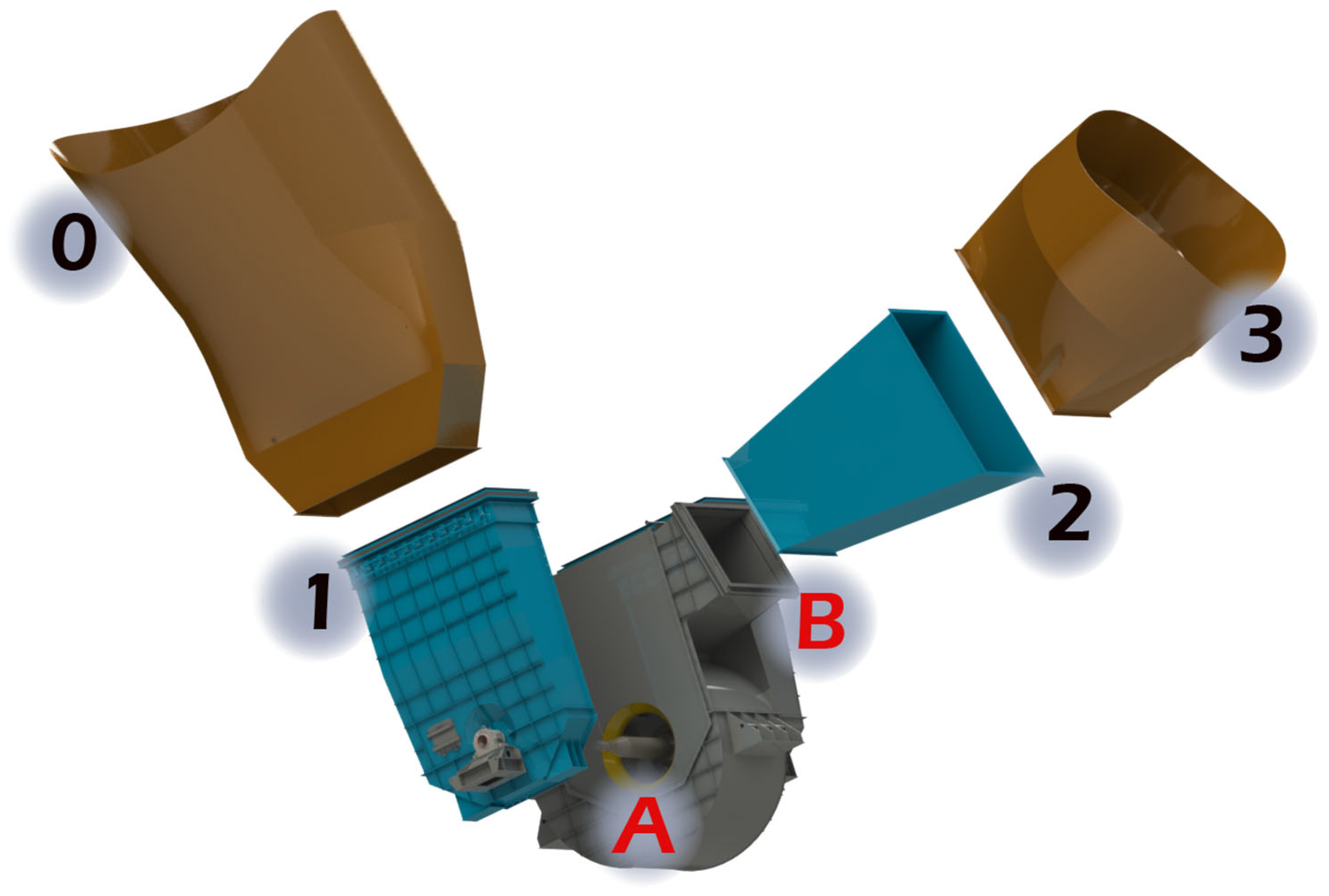
Figure 1. Components and connection points in the three-dimensional model of the fan system.
Sustainability 17 10279 g001
Figure 2. The mesh structure of the narrow-body CFD analysis model of the flour kiln fan in the XY plane.
Sustainability 17 10279 g002
Figure 3. ID Fan Solution Network View.
Sustainability 17 10279 g003
Figure 4. Boundary Conditions for the Raw Kiln Fan CFD Analysis Model.
Sustainability 17 10279 g004
Figure 5. Geometric comparison of the narrow-body and wide-body fan configurations.
Sustainability 17 10279 g005
Figure 6. Raw Kiln Fan and ID Fan field visual and manufacturing stages.
Sustainability 17 10279 g006
Figure 7. Reduced body velocity vectors in the XY plane.
Sustainability 17 10279 g007
Figure 8. Velocity vectors in the narrowed body in the XY plane.
Sustainability 17 10279 g008
Figure 9. Narrowed body flow streamline.
Sustainability 17 10279 g009
Figure 10. Wide and revised body velocity vectors in the YZ plane.
Sustainability 17 10279 g010
Figure 11. Wide and revised body velocity vectors in the XY plane.
Sustainability 17 10279 g011
Figure 12. Wide and revised body flow streamline.
Sustainability 17 10279 g012
Figure 13. Flow streamline in the ID fan model.
Sustainability 17 10279 g013
Figure 14. Velocity vectors in the Y-Z plane of the ID fan model.
Sustainability 17 10279 g014
Table 1. Targeted Fan Values.
Fan TypeFlow Rate (m3/h)Static Pressure (Pa)Total Pressure (Pa)Shaft Power (kW)Efficiency (%)
Flour Kiln Fan601,24121562447490.183
ID Fan441,64387448544121783
Table 2. Comparative Summary of Fan Geometry.
Design ParameterNarrow-Body FanWide-Body Fan
Total Casing Width1982 mm2520 mm
Outlet Width1808 mm1858 mm
Vortex BreakerNot presentIncluded
Shaft Cone GeometryUnoptimizedOptimized
Separation ObservedYes (in tongue)Minimized
Expected Flow UniformityLowHigh
Table 3. Comparison of flour kiln fan design objectives and CFD results.
ParametersDesign ValueCFD Analyses Results
Flow rate (m3/h)601,241601,241
Static Pressure (Pa)21562200
Total Pressure (Pa)24472580
Shaft Power (kW)490.1520
Efficiency (%)8383
Table 4. Comparison of ID fan design objectives and CFD results.
ParametersDesign ValueCFD Analyses Results
Flow rate (m3/h)441,643441,643
Static Pressure (Pa)87448653
Total Pressure (Pa)85449203
Shaft Power (kW)12171356
Efficiency (%)8383.24
Table 5. Comparison of results measured with the old and new fan.
ParameterOld Fan (15 November 2023)New Fan (8 May 2025, Corrected)Difference (New-Old)% Change
Volumetric Flow Rate (m3/h)401,494401,49400.0
Total Pressure (mmSS)742.7656.0−86.7−11.7
Shaft Power (kW)1204.9889.0−315.9−26.2
Total Efficiency (%)67.480.6+13.2 pp+19.6
Table 6. Comparison of the results measured with the old and new flour kiln fans.
ParameterOld Fan (15 November 2023)New Fan (8 May 2025)Difference (New-Old)% Rate of Change
Flow Rate (m3/h)388,681331,880−56,801−14.6
Total Pressure (mmSS)102.4102.40.00.0
Shaft Power (with kiln) (kW)162.9106.8−56.1−34.4
Total Efficiency (%)66.586.7+20.2+30.4
Disclaimer/Publisher’s Note: The statements, opinions and data contained in all publications are solely those of the individual author(s) and contributor(s) and not of MDPI and/or the editor(s). MDPI and/or the editor(s) disclaim responsibility for any injury to people or property resulting from any ideas, methods, instructions or products referred to in the content.