Article

Thermal Performance Analysis of Borehole Heat Exchangers Refilled with the Use of High-Permeable Backfills in Low-Permeable Rock Formations

1
National Center for International Research on Deep Earth Drilling and Resource Development, Faculty of Engineering, China University of Geosciences (Wuhan), Wuhan 430074, China
2
Key Laboratory of Shallow Geothermal Energy, Ministry of Natural Resources of the People’s Republic of China, Beijing 100195, China
*
Author to whom correspondence should be addressed.
Sustainability 2025, 17(19), 8851; https://doi.org/10.3390/su17198851
Submission received: 26 August 2025 / Revised: 27 September 2025 / Accepted: 29 September 2025 / Published: 3 October 2025
(This article belongs to the Section Sustainable Engineering and Science)

Abstract

It is well known that the operation of a Borehole Heat Exchanger (BHE) can thermally induce groundwater convection in aquifers, enhancing the thermal performance of the BHE. However, the effect on the thermal performance of BHEs installed in low-permeable rock formations remains unclear. In this study, two BHEs were installed in a silty sandstone formation, one backfilled with high-permeable materials and the other grouted with sand–bentonite slurry. A Thermal Response Test (TRT) showed that the fluid outlet temperature of the high-permeable-material backfilled BHE was about 2.5 °C lower than that of the BHE refilled with sand–bentonite slurry, implying a higher thermal efficiency. The interpreted borehole thermal parameters also show a lower borehole thermal resistance in the high-permeable-material backfilled BHE. Physical model tests reveal that groundwater convective flow was induced in the high-permeable-material backfilled BHE. A test of BHEs with different borehole diameters shows that the larger the borehole diameter, the higher the thermal efficiency is. Thus, the thermal performance enhancement was attributed to two factors. First, the induced groundwater flow accelerates heat transfer by convection. Additionally, the increment of the thermal volumetric capacity of the groundwater stored inside a high-permeable-material refilled borehole stabilized the borehole’s temperature, which is key to sustaining high thermal efficiency in a BHE. The thermal performance enhancement demonstrated here shows potential for reducing reliance on fossil-fuel-based energy resources in challenging geological settings, thereby contributing to developing more sustainable geothermal energy solutions. Further validation in diverse field conditions is recommended to generalize these findings.

1. Introduction

Amid the accelerating global transition toward low-carbon energy systems, ground-source heat pump (GSHP) technology has become a highly efficient and environmentally sustainable solution for building air-conditioning systems [1]. Borehole heat exchangers (BHEs) are the primary component facilitating heat exchange between the subsurface environment and the heat pump unit of GSHP systems [2]. In conventional BHE installations, low-permeability bentonite or cementitious materials are typically used as backfills, forming a multi-stage thermal resistance path: convective heat transfers from the working fluid to the pipe wall and conducts through the pipe, through the backfill materials, and finally into the surrounding soil or rock. This conduction-dominated mechanism substantially increases the borehole thermal resistance (Rb), leading to thermal accumulation around the borehole that degrades the system’s efficiency over time [3,4]. This issue remains a major technical bottleneck limiting the wider application of GSHP systems [5,6].
To address this concern, materials such as steel slag and graphite have been introduced to enhance the thermal conductivity of the refilling materials by 15–30% [7]. However, such materials incur higher costs and yield only marginal short-term improvements. Beyond conductivity optimization, researchers have explored methods to reduce Rb by leveraging groundwater flow [8,9]. Gustafsson [10] observed nonlinear Rb behavior in groundwater-filled BHEs subjected to thermal cycling and proposed a segmented evaluation method. Through multi-injection rate thermal response tests (MIR-TRT), they demonstrated that heat-induced natural convection could reduce Rb by 46% and increase the effective thermal conductivity by 34% in fractured rock formations [11]. Further CFD simulations confirmed that local convection could significantly reduce Rb even without ambient groundwater flow [12]. Johnsson et al. [13] integrated natural convection correlations into BHE performance models, reducing Rb prediction errors by nearly 50%. Chiasson [14] and Spitler et al. [15] developed aquifer-coupled heat transfer models and highly accurate universal dimensionless correlations (errors < 10%) to account for seepage-induced enhancements. Wang et al. [16] further validated these findings in field TRT measurements, showing an average 11.35% increase in BHE heat transfer efficiency under natural groundwater flow conditions. Groundwater movement also attenuates thermal buildup and reduces temperature amplitude near the borehole [17]. Luo et al. [18] reported a 25.9% thermal performance deficit in aquitard settings compared to aquifers, attributing the difference to contrasts in hydraulic conductivity. Using gravel to backfill BHE in aquifers reduced fluid outlet temperatures by 2.0 °C to 2.4 °C [19,20].
While significant research has focused on enhancing BHE performance in aquifer-rich or fractured rock formations through groundwater advection, the potential of engineered high-permeable backfills in low-permeable geological settings (e.g., clay or siltstone strata) has been insufficiently explored. This gap is critical, as such formations lack natural groundwater flow to mitigate thermal accumulation. Therefore, the main purpose of this study is to investigate whether artificially creating a permeable zone inside a borehole using novel high-permeable materials can induce and sustain convective heat transfer, thereby improving thermal performance. To achieve this goal, this study will (1) conduct field TRTs on two contrasting BHEs—one backfilled with high-permeable materials and another grouted with traditional low-permeable slurry—in a low-permeable rock formation; (2) develop physical models to evaluate the influence of borehole diameter on thermal performance and visualize convective flow patterns within the borehole. The findings provide insights into heat transfer mechanisms and offer practical strategies for enhancing the performance of GSHP systems in low-permeable geological settings.
As mentioned above, most previous studies have focused on aquifer-rich or fractured rock under groundwater flow conditions. In low-permeable geological settings such as clay or siltstone strata, the use of these types of backfills has been insufficiently explored. To better understand this concern, two BHEs were backfilled with high-permeable materials, and the other grouted using non-permeable slurry in low-permeable rock formations. Field thermal response tests (TRT) were conducted to examine the thermal performance of these BHEs. Physical model tests were implemented to evaluate the influence of borehole diameter on thermal performance and to visualize the behavior of convective flow in boreholes. This work introduces three key novelties: (1) the application of a novel engineered high-permeable hollow material as a backfill, designed to create a stable and sustainable flow path for convection; (2) a focus on enhancing BHE performance in low-permeable silty sandstone formations, where the conventional systems suffer from thermal accumulation; (3) a systematic evaluation of the synergistic effect of borehole diameter with such backfills, providing new insights for design optimization. By combining field TRTs with controlled laboratory experiments, this study aims to establish a new strategy for developing efficient GSHP systems in such geological settings. The remainder of this paper is organized as follows: Section 2 presents the site-specific geological conditions, TRT methodology, and physical model test setup. Section 3 discusses the experimental results, focusing on the heat transfer mechanisms of BHE. Finally, Section 4 summarizes this study’s key findings and engineering implications.

2. Materials and Study Methodology

2.1. Geological Setting

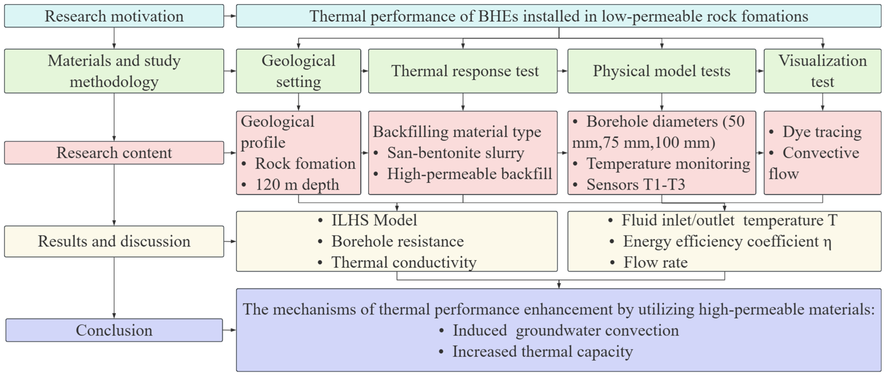
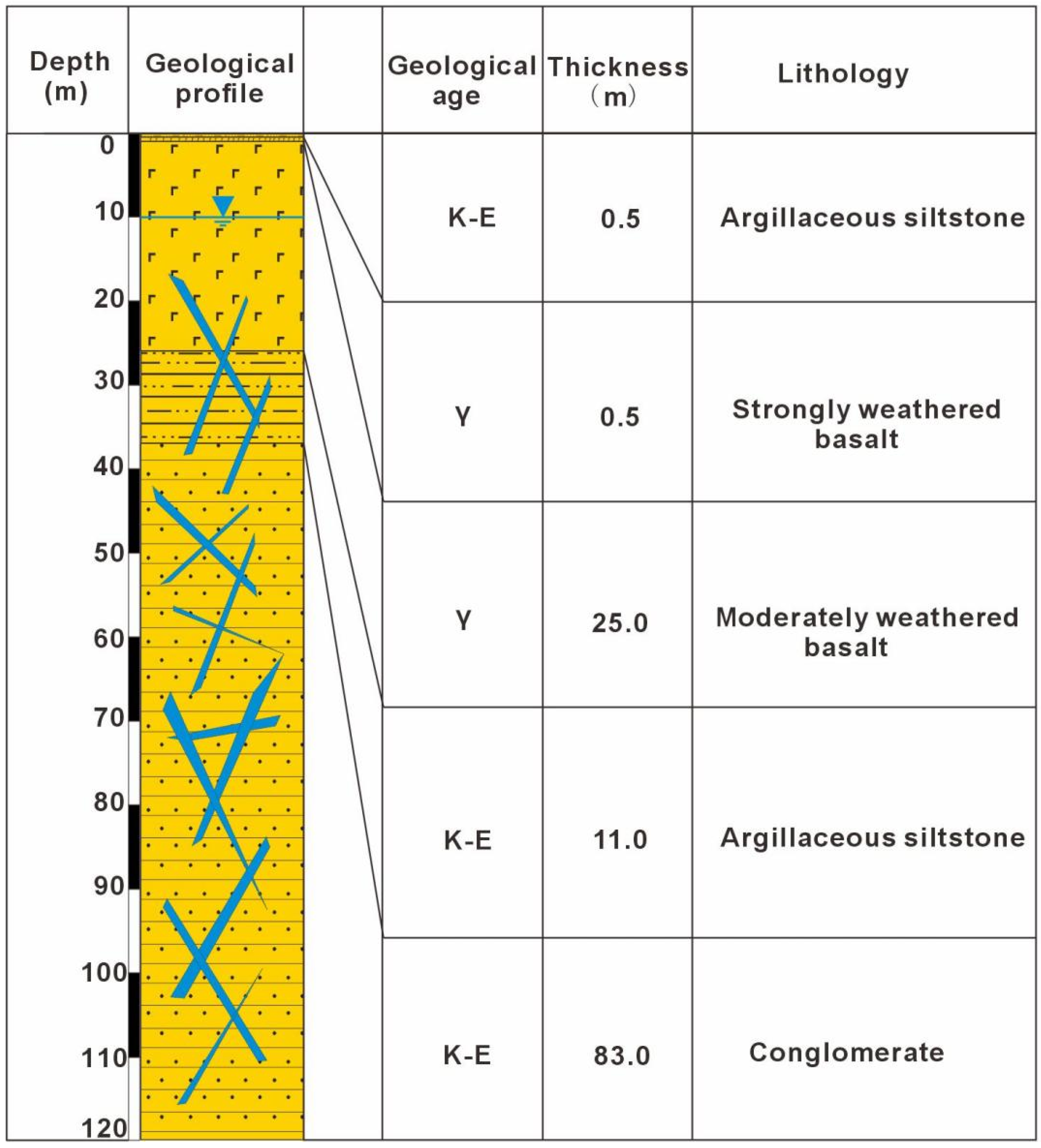
Figure 1 shows the diagram of the experimental process design. The study area was located in Ezhou City, Hubei Province, China (longitude 114°32′–115°05′ E, latitude 30°00′–30°06′ N), which is situated in the middle reaches of the Yangtze River in the subtropical monsoon climate zone. The geological layers within a 120 m depth below the surface, as revealed by the drilling logs presented in Figure 2 of this study, were mainly composed of argillaceous siltstone, basalt, and conglomerate. The groundwater types comprised perched water in the ground surface with a very thin Quaternary deposit and bedrock fissure water. Bedrock fissure water is mainly found in tectonic and weathering fissures in argillaceous siltstone, conglomerate, and basalt. This geological and hydrogeological condition caused the borehole to be filled with groundwater after it was drilled.
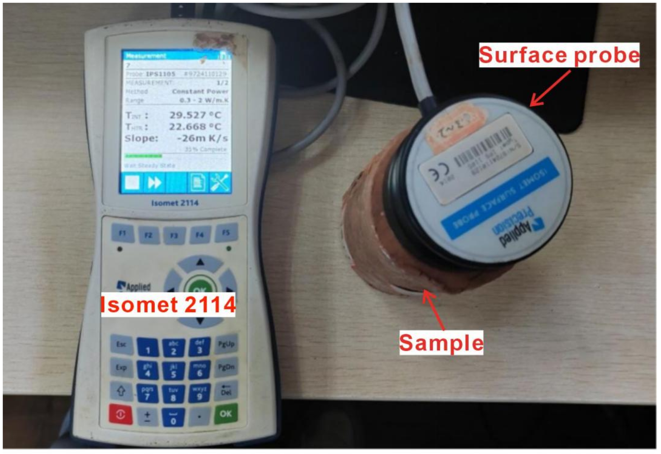
Thermophysical parameters, including thermal conductivity (λ), volumetric heat capacity (), and thermal diffusion coefficient (α), were measured in the collected drilling cores. To ensure the accuracy and reliability of the measurement data, all the geotechnical samples to be measured were rigorously cut and surface polished, as shown in Figure 3. This is to eliminate surface unevenness to reach perfect thermal contact between the sample and the probe. The specific values measured by the device are fully documented and summarized in Table 1.

2.2. Field Thermal Response Test

2.2.1. BHE Installation

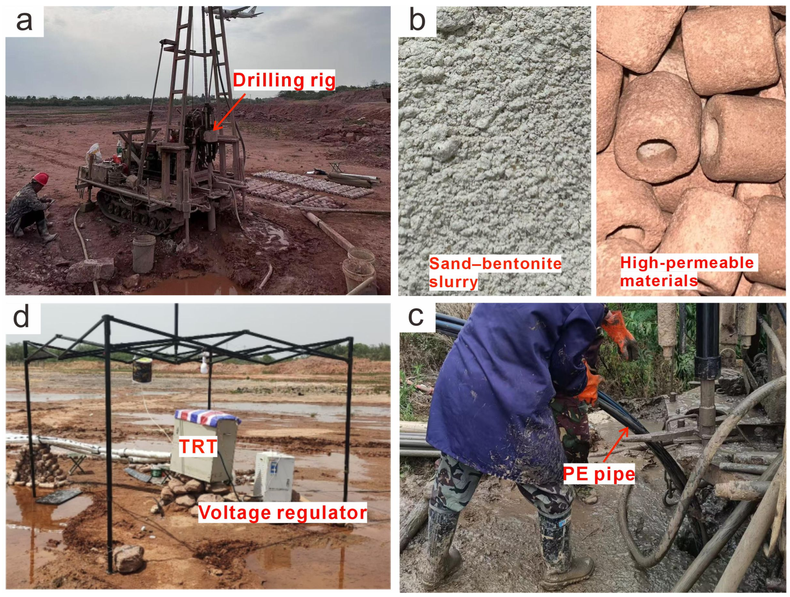
Two boreholes were drilled with the same diameter of 150 mm and a depth of 120 m, as shown in Figure 4. A single U-type PE pipe was inserted into the borehole with a nominal diameter of 32 mm, a wall thickness of 3 mm, and a thermal conductivity of 0.42 W/(m·K). The space between the PE pipe and the surrounding rock was backfilled. One borehole was grouted with a sand–bentonite slurry, with a ratio of sand to bentonite of 1:5. The other borehole was backfilled with high-permeable column-shaped hollow materials, as shown in Figure 3. The high-permeable backfill material used in this study was composed of concrete, specifically designed to be highly porous and durable. The units were fabricated as column-shaped hollow cylinders with an outer diameter of approximately 20 mm, an inner diameter of 15 mm, and a length of 30 mm. This geometry creates a large surface area and an interconnected pore network conducive to fluid flow. The packed bulk material exhibited a porosity of 44% and an estimated hydraulic conductivity (K) in the order of 10−2 m/s, classifying it as a high-permeable medium capable of facilitating strong convective flow. While the material showed no signs of degradation during the testing period, it should be noted that its long-term chemical and mechanical stability under continuous thermal cycling and in various groundwater chemistries remains an important consideration for future field applications and should be determined in subsequent investigations.

2.2.2. Monitoring of the Temperature Response

To test the BHE’s heat transfer performance with two different types of backfill materials, TRT was implemented as shown in Figure 5. The TRT instrument (Model: TRTDV 2.0) was designed by the Geological Engineering Experimental Center of China University of Geosciences (Wuhan). The TRT has a heating tube, flow meter, temperature sensor, and paperless recorder. The heating tube can achieve three heating powers of 3 kW, 6 kW, and 9 kW, with an accuracy of ±1%. The flow meter has a measurement range of 0–2 m3/h, with an accuracy of ±1%. The temperature sensor has a measuring range of 0–100 °C and an accuracy of ±0.2 °C. In this study, two BHEs were tested using pure water as the heat transfer fluid under a constant heating power of 6 kW and a flow rate of 1.4 m3/h. The inlet and outlet fluid temperatures, the flow rate, and the heating power were automatically logged with a minute interval.

2.2.3. Thermal Performance Analysis of BHE

The energy efficiency coefficient η is one of the main parameters used to measure the heat transfer performance of BHE, which is calculated as follows [21]:
η = T i n T o u t T i n T 0
where η denotes the energy efficiency coefficient of BHE (−), Tin denotes the fluid inlet temperature of the fluid in the ground source heat pump system (°C), Tout denotes the fluid outlet temperature of the fluid in the ground source heat pump system (°C), and T0 denotes the initial ground temperature (°C).
In this study, the TRT recorded the data and analyzed it using the Infinite-Line-Heat-Source (ILHS) model, and the average fluid temperature of the heat-carrying fluid was obtained [22,23].
To quantify the enhancement of convective heat transfer relative to pure heat conduction, the Nusselt number (Nu) was referred to, and it is given as follows:
N u = h L c λ
Q a = m C p ( T i n T o u t )
Q a = h A ( T w a l l T )
where Q a is the actual heat transfer rate of the BHE (W), m is the mass flow rate of water (kg/s), C p is the specific heat capacity of water (J/(kg·K)), T i n is the inlet temperature of water in the BHE (°C), T o u t is the outlet temperature of water in the BHE (°C), h is the convective heat transfer coefficient for the borehole backfilling (W/(m2·K)), A is the heat transfer area of the outer wall of the BHE (m2), T w a l l is the borehole wall temperature (°C), T is the initial temperature (°C), L c is the characteristic length (m), and λ is the thermal conductivity of water (W/(m·K)) [24].

2.3. Heat and Flow Transfer in Weakly Permeable Ground

2.3.1. Heat Transfer of High-Permeable Materials

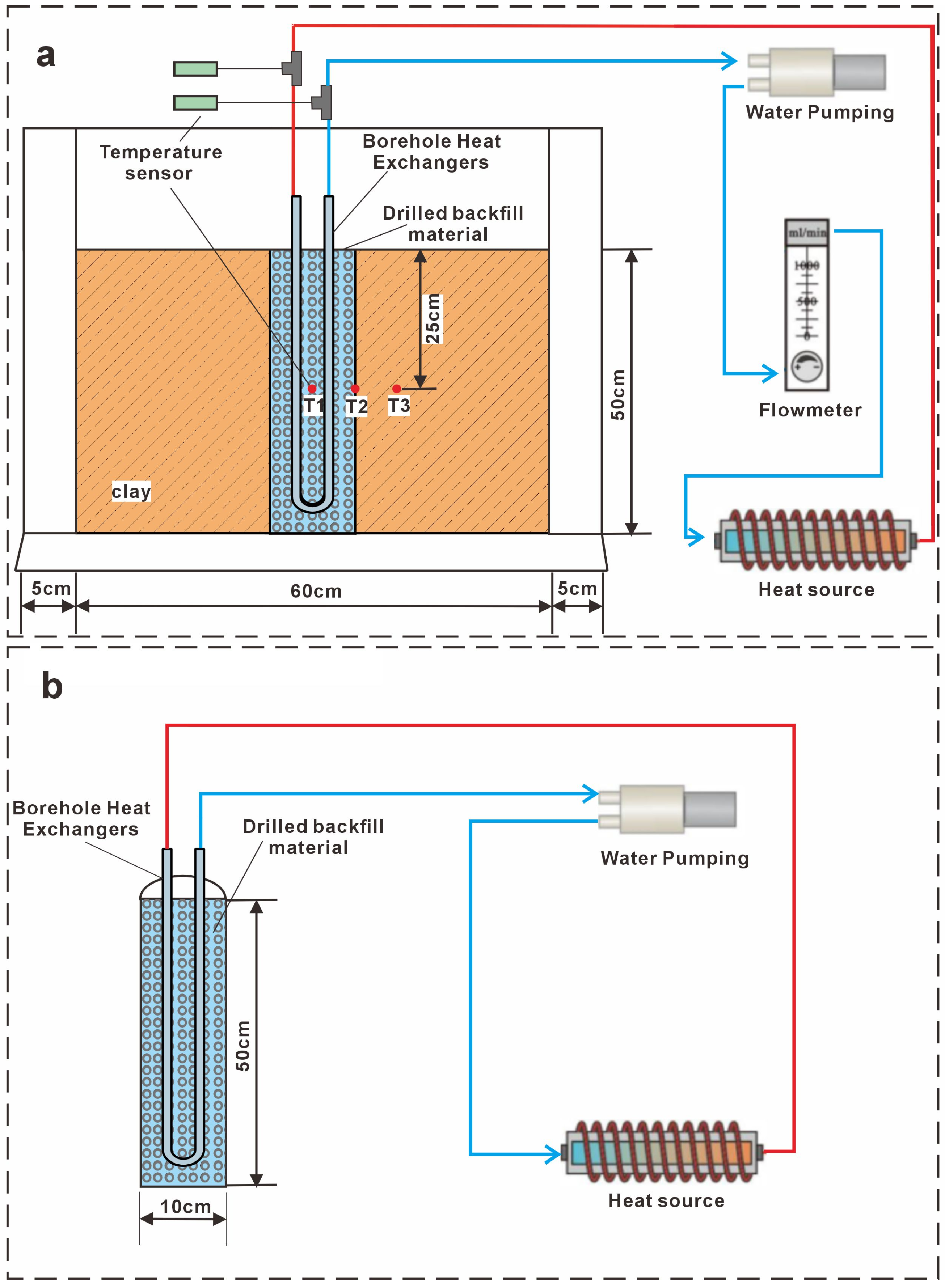
Physical model tests were conducted under varying borehole diameters to further investigate the effects of groundwater volume inside a borehole on the heat transfer performance of BHE in weakly permeable strata. The test apparatus comprised an acrylic plexiglass box with a length of 700 mm, 400 mm in width, and 600 mm in height. A 500 mm thick clay layer was compacted into the box to simulate a weakly permeable formation. A vertical BHE was centrally embedded within the clay layer, and the surrounding annulus was filled with designated backfill materials. The system was connected to a circulation loop comprising a pump, heater, rotor flowmeter, and temperature sensors, as illustrated in Figure 6a. Two backfills were employed: sand–bentonite slurry and a high-permeable hollow material. This is to investigate the impact of high-permeable materials on the thermal performance enhancement of BHE. Three saturated boreholes with diameters of 50 mm, 75 mm, and 100 mm were tested to understand the mechanism better. The detailed experimental matrix is listed in Table 2.
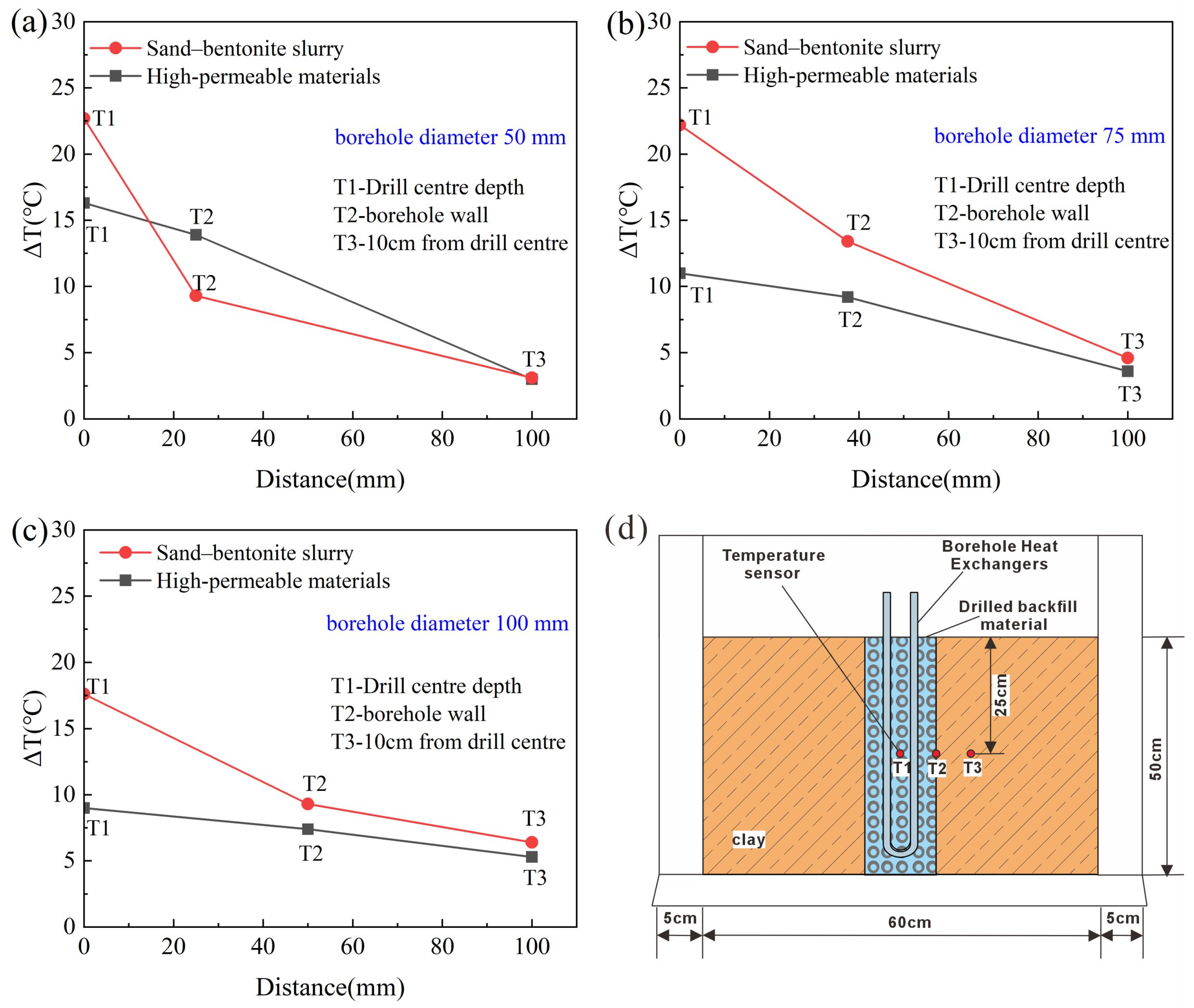
To further elucidate the convective flow effects on the heat transfer performance of a BHE, soil temperature response during the heating was monitored at a depth of 25 cm. Sensors were installed in three positions: the borehole center, the borehole wall, and the surrounding formation 10 cm from the center. The sensor layout is also depicted in Figure 6a. The experimental setup is summarized in Table 3.

2.3.2. Heat and Flow Transfer of a BHE in a Borehole

To understand the heat transfer enhancement of the boreholes backfilled with high-permeable materials compared to those grouted with sand–bentonite slurry. A semi-cylindrical model was built to simulate a borehole with a diameter of 10 cm and a height of 50 cm. A U-shaped pipe was placed inside the cavity, connected to a circulating loop consisting of a water pump and heater. The annular space was backfilled with high-permeable material or sand–bentonite slurry, and the borehole interior was saturated with groundwater.
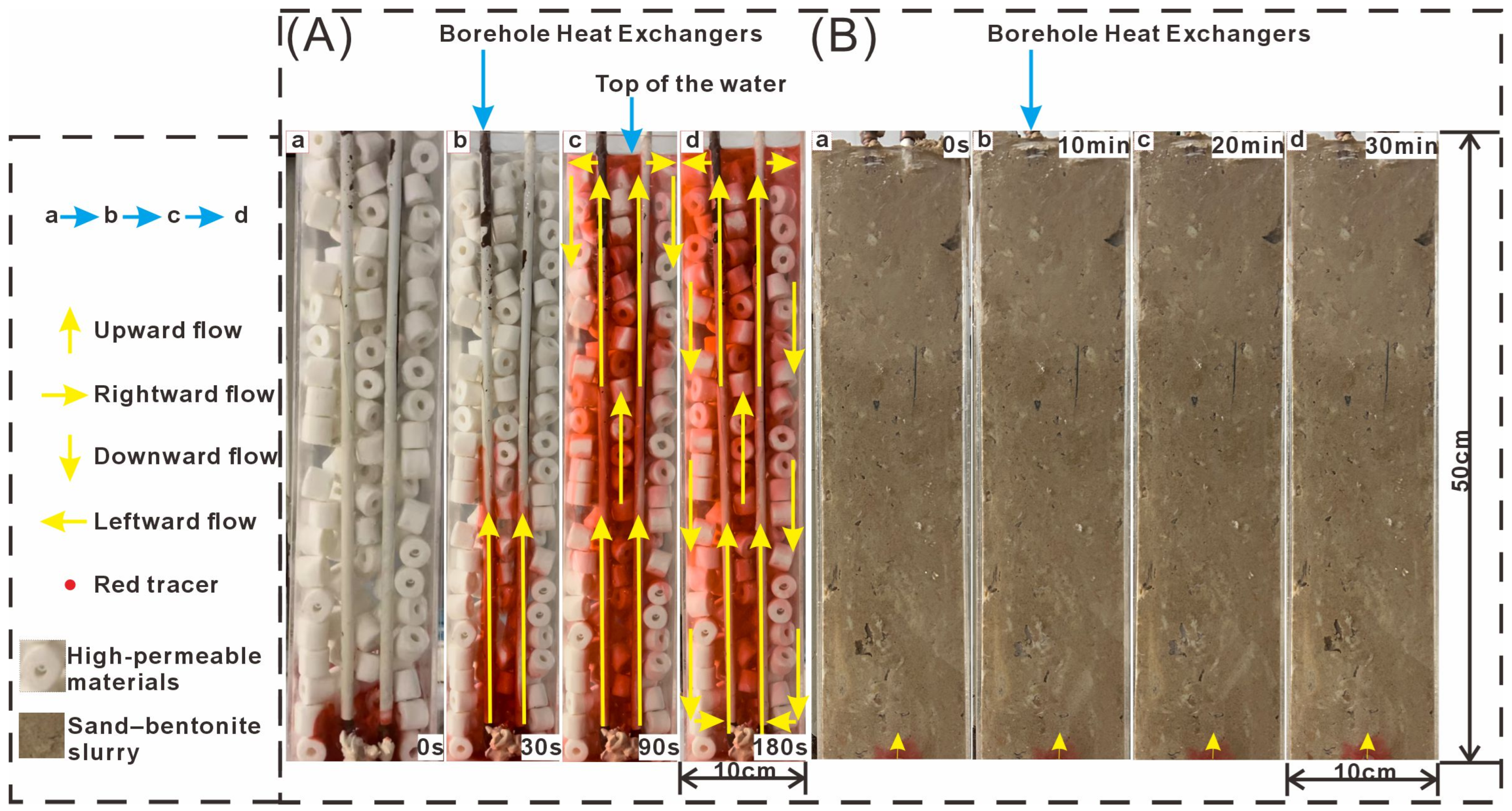
To visualize the behavior of thermally induced convective flow inside a borehole, red dye was deployed to trace the groundwater movement during the heating process. A camera was placed in front of the container to record the dye’s movement within a certain time interval, as illustrated in Figure 6b.
The physical model experiments were designed to provide qualitative insights into heat transfer mechanisms and enable visualization of flow processes rather than to achieve strict geometric or dynamic similarity for direct quantitative scaling to full-field conditions. The primary objectives were to (1) visually confirm the establishment of thermally driven convection within the borehole annulus; (2) analyze the relative performance of different backfill materials and borehole diameters under controlled conditions. While scale effects prevent the direct extrapolation of absolute values (e.g., temperature reductions, Nusselt numbers), the consistent trends observed indicate the fundamental mechanisms. The field thermal response tests provide the necessary complementary data at the engineering scale, while the laboratory model provides the mechanistic explanation for the field observations.

3. Results and Discussion

3.1. Heat Transfer Performance

Two TRTs were implemented, and the temperature development of the heat-carrier fluid was recorded as shown in Figure 7a. The fluid outlet temperatures of the BHEs with high-permeable-material-filled boreholes were lower than those of the BHEs with sand–bentonite slurry. After 42 h of operation of the system, the fluid outlet temperature of the BHEs backfilled with sand–bentonite reached 29 °C. In contrast, the fluid outlet temperature of the BHEs backfilled with high-permeable materials increased to 27 °C, with a mean temperature of 2.5 °C lower. This implies that the heat transfer efficiency of BHE backfilled with sand–bentonite slurry can be improved by refilling it with high-permeable materials.
The energy efficiency coefficient of these two BHEs was calculated and demonstrated in Figure 7b. The energy efficiency coefficient decreased rapidly with time at the beginning of the test and maintained a nearly constant value after a 9-h testing period. Finally, the energy efficiency coefficient of the high-permeable-material backfilled BHE remained constant at 0.33, while the other one was 0.27, which was 22% higher. The coefficient of the high-permeable-material backfilled BHEs was much higher than that of the BHEs that were sand–bentonite-slurry-grouted, resulting in higher thermal performance.

3.2. Borehole Thermal Parameters

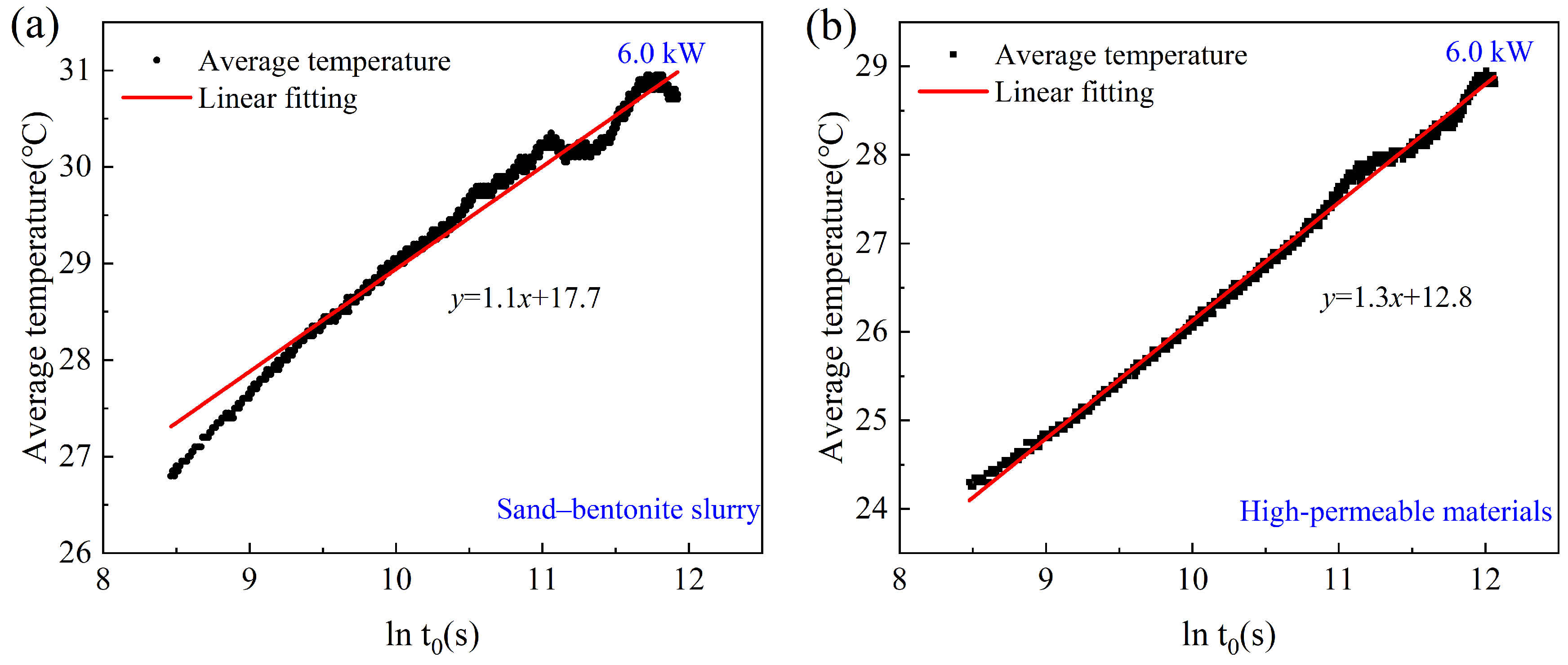
The arithmetic mean temperature of the heat-carrier-fluid and the logarithmic time were linearly fitted by following the Line Heat Source (LHS) model, as shown in Figure 8. The interpreted thermal conductivity and borehole thermal resistance of the two types of backfills are listed in Table 4. The high-permeable-material backfilled BHE had a borehole thermal resistance of 0.06 (m·K)/W, which is nearly half that of the sand–bentonite-slurry-grouted BHE, which was 0.11 (m·K)/W. Using high-permeable materials caused a drastic reduction of 45.5% in borehole thermal resistance.
On the other hand, the effective thermal conductivity of the ground was also interpreted, and the results showed that the BHE grouted using sand–bentonite slurry had an higher thermal conductivity. This means that this BHE could achieve a better thermal performance even if the setup of the other borehole’s materials and configuration remained the same. The initial ground temperature was measured at both borehole locations, equal to 20 °C.
The apparent paradox of a higher-interpreted effective thermal conductivity (λeff) yet poorer thermal performance for the sand–bentonite backfill can be explained by the limitations of the conduction-based interpretation model when applied to a system with internal convection. The Infinite Line Heat Source model attributes all heat transfer efficiency to the borehole resistance (Rb) and ground conductivity (λeff). Vigorous convection within the borehole provides an additional, unmodeled heat transfer mechanism in the high-permeable backfill. The model compensates for this enhanced efficiency by interpreting it as a very low Rb and a moderately high λeff combination. In the sand–bentonite case, which aligns with the model’s conductive assumption, the interpreted λeff is likely a more accurate representation of the true formation conductivity. Thus, the higher λeff value alongside poorer performance is not an inconsistency but a hallmark of the convective process, with the drastic reduction in Rb being the true indicator of performance enhancement.
To improve the reliability of the interpreted borehole thermal parameters, an error propagation analysis was carried out by considering the uncertainties of the temperature sensors (±0.1 °C), flowmeter (±2%), and power input stability (±1%). The uncertainties reported in Table 4 represent one standard deviation. Even when these uncertainties are accounted for, the reduction in borehole thermal resistance by 45.5% in the high-permeable backfilled BHE remains statistically significant, reinforcing the robustness of the observed performance enhancement.

3.3. Heat Transfer of BHE in Physical Model Test

3.3.1. Heat Transfer of BHE with Different Refilling Materials

As illustrated in Figure 9, the fluid outlet temperature with high-permeable materials was 41.0 ± 0.2 °C with a 100 mm borehole diameter, which is notably lower than that of a sand–bentonite slurry refilled borehole, which has a 52.7 ± 0.3 °C fluid outlet temperature. Concurrently, the energy efficiency coefficient increased from 0.153 to 0.299 with a 100 mm diameter borehole, accounting for a 95.4% improvement. Including propagated uncertainties from sensor precision (±0.1 °C) and power input stability (±1%) yields η values of 0.299 ± 0.01 and 0.153 ± 0.01, respectively. ANOVA analysis across replicate runs confirmed that these differences are statistically significant (p < 0.01), demonstrating that the observed enhancement is not attributable to measurement error. The physical model tests were consistent with the results observed in the field TRT.

3.3.2. Heat Transfer Performance of BHE with Different Borehole Diameters

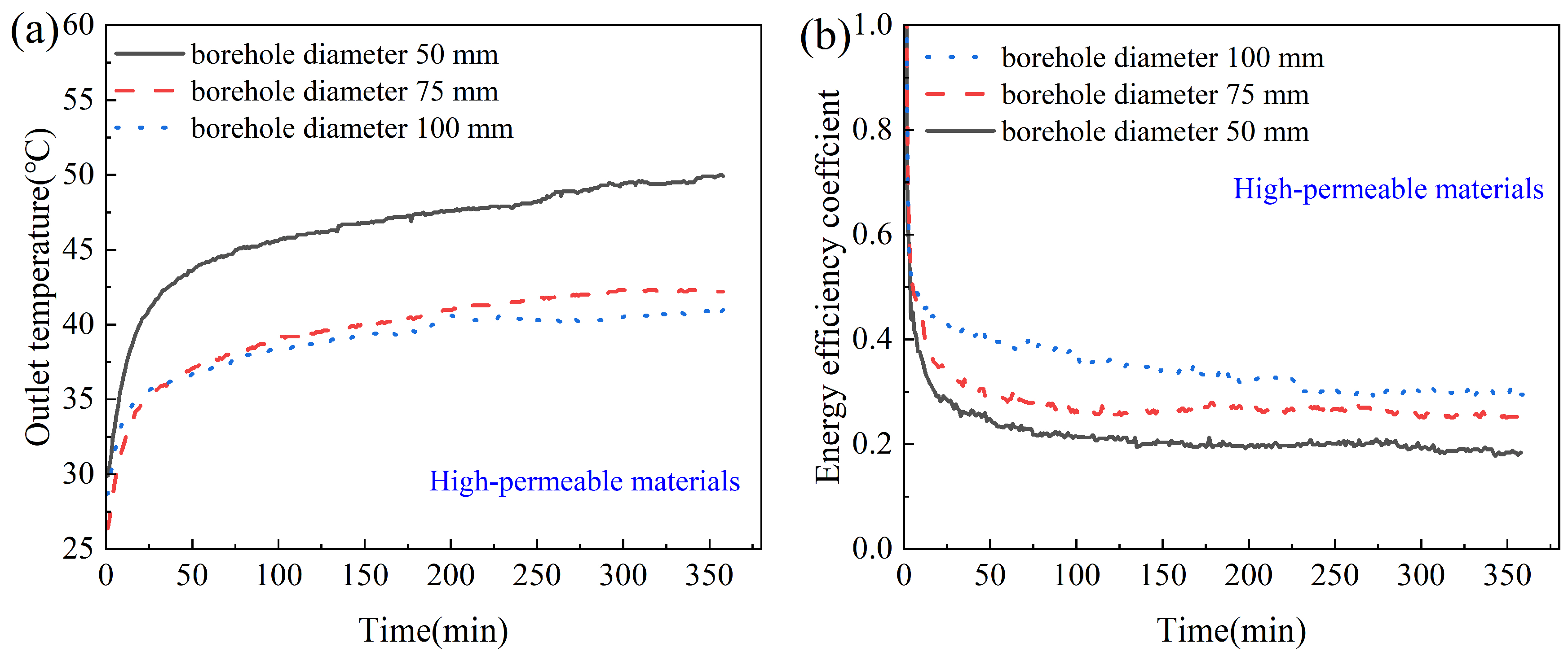
To better understand the effects of groundwater inside boreholes on the thermal performance of BHE, boreholes with three different diameters were prepared, with an increase in borehole diameter from 50 mm to 75 mm to 100 mm. A decreasing trend of fluid outlet temperature from 49.9 °C to 42.2 °C, and then to 41.0 °C was observed when the high-permeable materials were applied. The corresponding energy efficiency coefficient gradually increased from 0.184 to 0.252 to 0.299, as shown in Figure 10. The energy efficiency coefficient of the borehole with a 100 mm diameter increased by 62.5% compared with that of the 50 mm diameter.
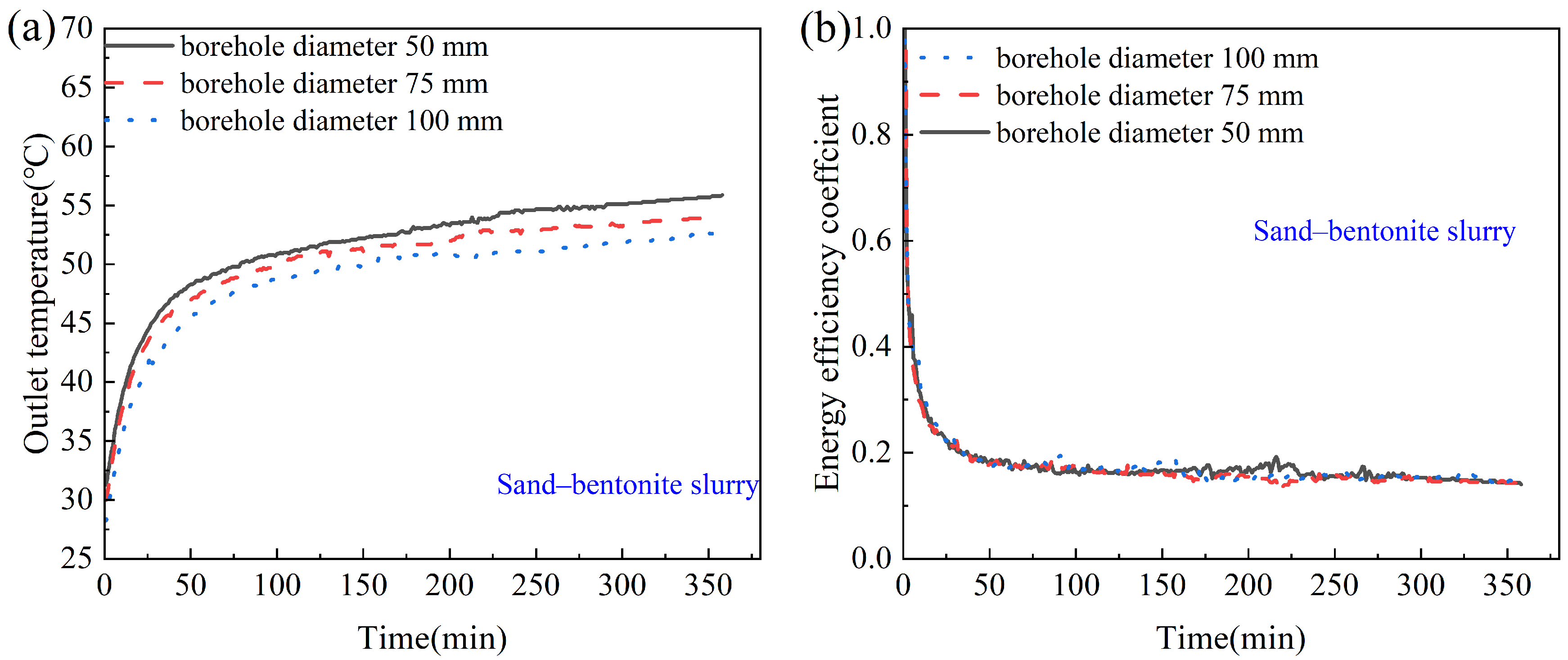
On the other hand, the fluid outlet temperature decreased from 55.9 °C to 54.0 °C, then to 52.7 °C for the BHE refilled with sand–bentonite slurry, with energy efficiency coefficients increasing from 0.140 to 0.143, and then to 0.153, as shown in Figure 11. The energy efficiency coefficient improved by only 9.3% when the borehole diameter was increased from 50 mm to 100 mm.
Figure 10 and Figure 11 provide further insight into the diameter effect. For high-permeable backfills, enlarging the borehole from 50 mm to 100 mm reduced outlet temperature from 49.9 ± 0.2 °C to 41.0 ± 0.2 °C and raised η from 0.184 ± 0.01 to 0.299 ± 0.01, an increase of 62.5% with uncertainties considered. By contrast, the sand–bentonite slurry cases showed only minor improvements (η rising from 0.140 ± 0.01 to 0.153 ± 0.01, or 9.3%), which falls within the propagated error range, indicating the effect of diameter increase is not statistically significant for low-permeable backfills. These findings highlight that the synergistic effect of increased groundwater volume and induced convection dominates the performance improvement, whereas conduction-dominated systems remain relatively insensitive to diameter changes.
The energy efficiency coefficient (η) in Equation (1) is employed in this study as a system-level performance metric to directly compare the heat exchange efficiency between the two BHE designs under identical operational conditions. While η depends explicitly only on temperatures, it implicitly captures the integrated effect of all heat transfer processes within the borehole, including the critical influence of backfill permeability. A high-permeability backfill enhances convective heat transfer, resulting in a lower outlet temperature (Tout) for a given inlet temperature (Tin), yielding a higher η value. Thus, the difference in η is a direct consequence of the difference in permeability. It is important to note that η is a comparative metric for a fixed set of operational conditions. It is most meaningful when used alongside fundamental parameters like borehole thermal resistance (Rb).
The findings mentioned above indicate that the increase in borehole diameter refilled with high-permeable materials effectively enhanced the thermal performance of BHE. It has been reported that the increased thermal capacity inside a borehole can improve the thermal performance of BHE. In this study, thermal capacity inside a borehole was increased by enlarging the groundwater volume inside the borehole. Thus, using high-permeable backfills can also enhance thermal capacity inside a borehole, sustaining thermal performance by stabilizing the temperature inside a borehole.
In summary, when error propagation and statistical testing are incorporated, the improvements observed in Figure 8, Figure 9, Figure 10 and Figure 11 remain significant and robust. This confirms that the deployment of high-permeable backfills not only reduces borehole thermal resistance but also magnifies the positive impact of increasing borehole diameter, establishing a dual mechanism of convective enhancement and thermal capacity stabilization.

3.3.3. Temperature Response of BHE in Constant Heat Power

The temperature response at borehole center T1, wall T2, and surrounding stratum T3 was monitored during the heating process as shown in Figure 12. It shows that the temperature at the center of the borehole, T1, filled with high-permeability material, was lower than that of the sand–bentonite-slurry-backfilled BHE for all three diameters. In T2, at the borehole wall, the borehole with a 50 mm diameter had a higher temperature, but the other two diameters showed a similar trend to that in the borehole center. This could be attributed to the fact that the temperature at the borehole wall can be affected by the effective heat transfer coefficient and thermal capacity. In a high-permeability-material-backfilled borehole with a small diameter, the very fast increase in borehole wall temperature was mainly due to the convective heat transfer. The temperature can also be lowered when the thermal capacity inside a borehole is much higher, as is observed in Figure 12b,c. In T3, all three soil temperatures are similar, which indicates that the heat was not transferred to the monitored position during the test. The results demonstrate that using high-permeable materials can significantly reduce thermal accumulation inside a borehole and, in turn, improve the thermal performance of a BHE.

3.4. Heat Transfer Process of BHE Inside a Borehole

Dye visualization experiments were carried out to capture flow patterns of the thermally induced convective flow in the high-permeable-material-refilled BHE. As depicted in Figure 13A, the heated fluid flowed inside the borehole, spread radially when it touched the borehole top, and later descended along the walls and returned to the heat source at the bottom, forming a flow circuit. By considering the borehole diameter of 50 mm as a characteristic length L c , the heat exchange area A of the outer wall of the pipe is 0.01256 m2, the initial fluid temperature T of the BHE is 29.3 °C, the fluid inlet temperature T i n is 46.2 °C, and the fluid outlet temperature T o u t is 41 °C. The flow rate V is 200 mL/min, the wall temperature T w a l l after 6 h of heating is 36.7 °C, the density C p of water at 40 °C is 4178 J/(kg·K), and the λ of water is 0.63 W/(m·K). Then, the Nusselt number of 61.27 can be calculated for this system. A comparative analysis in Figure 13B confirms sand–bentonite slurry systems rely on conduction-dominated heat transfer, whereas high-permeable materials rely on convection-dominated heat transfer.
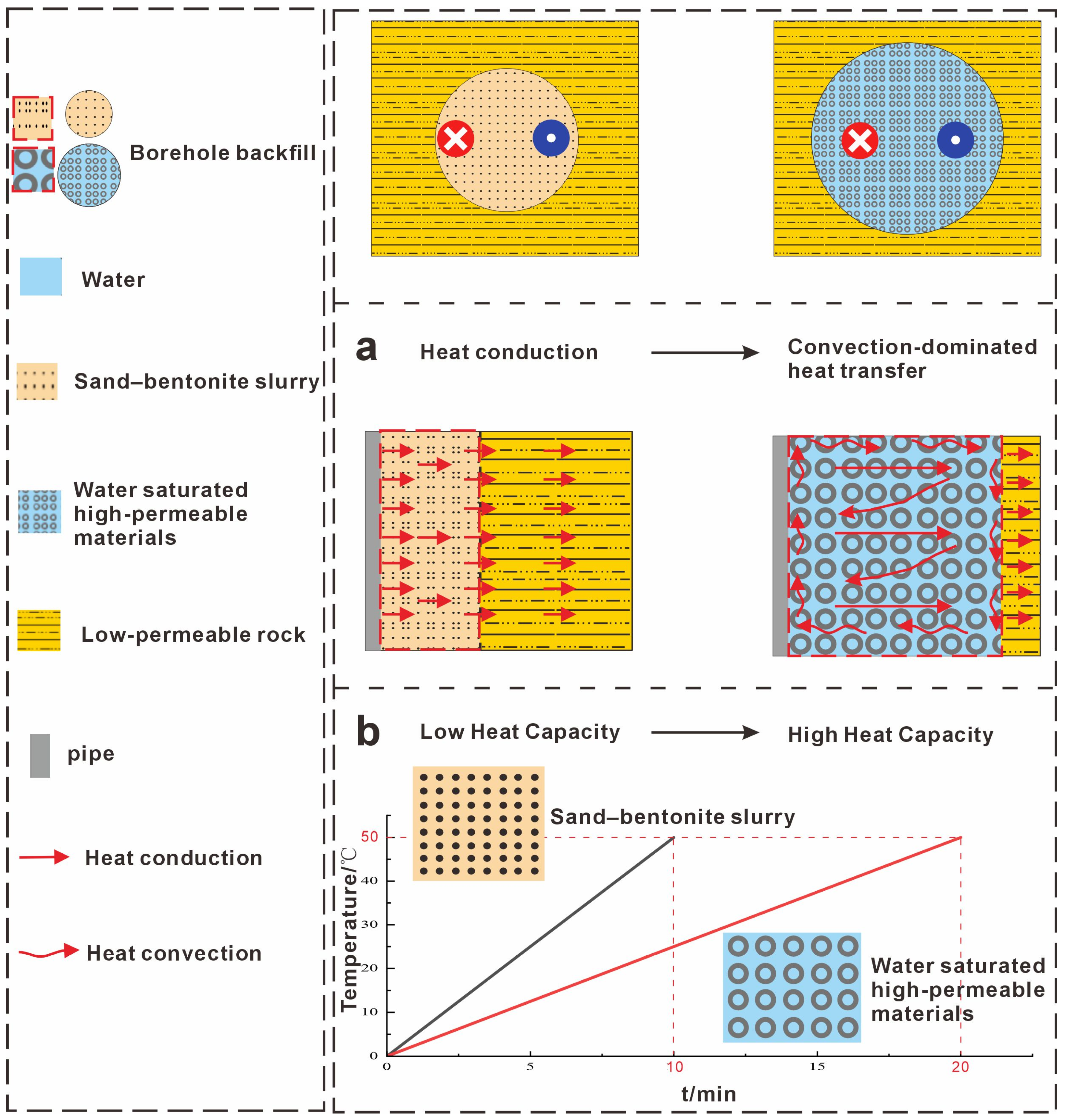
Conclusively, the enhancement of BHE thermal performance by deploying high-permeable materials can be attributed to two factors. First, the induced groundwater convection shifts the heat transfer mode from conduction-dominated to convection-dominated, significantly improving heat exchange efficiency. Second, the groundwater within the borehole increases the thermal capacity, thereby minimizing temperature fluctuations and helping sustain a stable temperature difference between the heat-carrier fluid and the surrounding ground. This mechanism supports the system’s high and stable thermal performance, as illustrated in Figure 14.

4. Conclusions

This study aims to enhance the thermal performance of BHEs in low-permeability formations by introducing high-permeability backfills. Thermal response tests (TRT) were carried out to simulate cooling-mode operation of BHEs, and physical model tests were conducted to reveal the role of the groundwater occupied borehole and to understand the thermally driven groundwater flow. The main conclusions drawn from this work are shown as follows:
  • The comparison of TRT results between BHEs backfilled with sand–bentonite slurry and those with high-permeability materials demonstrated that the latter had a 2.5 °C lower fluid outlet temperature. It indicates that thermal performance enhancement of BHE can be achieved by deploying high-permeable materials in low-permeable rock formations. Additionally, the energy efficiency coefficient increased by 18.5% relative to the sand–bentonite system, confirming the superior heat performance of the BHE with the use of high-permeable backfills.
  • Physical model tests showed that increased borehole diameter effectively reduced fluid outlet temperature using high-permeability materials. In a 100 mm diameter borehole, the fluid outlet temperature with high-permeable material backfill reached up to 49.9 °C. Compared with a 50 mm diameter borehole, the fluid outlet temperature was 8.9 °C lower, leading to an improved energy efficiency coefficient of 62.5%. Increasing the groundwater volume in a borehole will enhance thermal performance. The tracing of thermally induced groundwater flow by the operation of BHE showed that the fluid flowed upward along the pipe once it occurred. Later, it moved horizontally once it reached the water surface. It then descended along the borehole wall, eventually returning to the pipe surface, forming a continuous circuit. This process carried the heat generated at the pipe surface away, maintaining the temperature difference between the heat-carrier fluid and the borehole, thereby alleviating the thermal accumulation around the pipe, enhancing the heat performance.
  • The enhancement of the thermal performance of the BHE backfilled using high-permeable material is primarily attributed to two aspects: first, the conduction-dominated heat transfer of low-permeable-material-grouted BHE was transited to convection-dominated heat transfer when high-permeable materials were deployed due to the induced groundwater flow. The Nusselt number for the high-permeability material backfill was measured at 61.57, meaning the heat transfer on the pipe surface can be much faster than pure water heat conduction. On the other hand, the increment in volume of groundwater inside a borehole also acts as a temperature stabilizer due to the high specific heat capacity. The higher the volume of the groundwater inside a borehole, the more stable the borehole temperature can be achieved, resulting in a sustainable and high heat-transfer performance. Thus, these dual effects collectively enhance the overall system’s thermal performance as it is observed.
These findings underscore the practical value of using high-permeability backfill materials in low-permeability strata. Compared to water-filled borehole designs commonly used in crystalline bedrock, the backfill approach presented in this study demonstrates strong potential for application in similar low-permeability formations for soil and soft rock formations, demonstrating strong potential for wider and more general application. While the results are promising, broader generalization requires future validation across a wider range of geological and hydrological conditions.
This fluid outlet temperature reduction in cooling mode corresponds with the increasing of heat pump COP, lowering energy use, and operational emissions. There are even fewer costs compared to traditional backfilling materials, due to the fewer materials used in the hollow structure, thus enhancing the system’s efficiency without increasing initial investment.
This study has several limitations: the BHE numbers were limited (two boreholes), and the physical models were scaled, which may introduce scale effects. The long-term chemical and mechanical stability of the novel backfill materials was not clearly understood. Furthermore, a detailed economic analysis was beyond the scope of this study. Future work should include long-term monitoring of full-scale BHEs, numerical modeling to simulate and optimize design parameters, exploration of alternative low-cost and durable high-permeability materials, and a comprehensive life-cycle cost analysis to assess the economic feasibility of this technology. Despite these limitations, the results strongly indicate the potential of this approach to improve GSHP efficiency in challenging geological conditions worldwide.

Author Contributions

Y.L.: Software, Formal analysis, Data curation, Writing—original draft, Visualization. B.C.: Validation, Supervision, Project administration, Writing—review and editing. Y.X.: Software, Investigation, Writing—original draft. J.L.: Conceptualization, Methodology, Resources, Writing—original draft, Project administration, Writing—review and editing. All authors have read and agreed to the published version of the manuscript.

Funding

This work was Funded by the Key Laboratory of Shallow Geothermal Energy, Ministry of Natural Resources of the People’s Republic of China, No. KLSGE202501-18.

Institutional Review Board Statement

Not applicable.

Informed Consent Statement

Not applicable.

Data Availability Statement

The data presented in this study are available on request from the corresponding author due to privacy.

Conflicts of Interest

The authors declare no conflicts of interest. The authors declare that they have no known competing financial interests or personal relationships that could have appeared to influence the work reported in this paper.

Nomenclature

BHEBorehole Heat Exchanger
BHEsBorehole Heat Exchangers
TRTThermal Response Test
GSHPGround source heat pump
PEPolythene
λThermal conductivity (W/(m·K))
Volume heat capacity (MJ/m3·K)
αThermal diffusivity (m2/s)
TinFluid Inlet temperature (°C)
T o u t Fluid outlet temperature (°C)
mMass flow rate of water (kg/s)
hConvective heat transfer coefficient(W/(m2·K))
AHeat transfer area of the outer wall of the pipe(m2)
TwallBorehole wall temperature (°C)
TInitial temperature (°C)
tTime (s)
RbBorehole thermal resistance (m·K/W)
ηEnergy efficiency coefficient of a BHE (-)
QaActual heat exchanged in subsurface (kW)
ρDensity water (kg/m3)
CpSpecific heat capacity of water (J/(kg·K))
Lccharacteristic length (m)

References

  1. Shu, B.; Bao, Y.; Markides, C.N.; Besagni, G.; Moore, J. Overview and outlook of thermal processes in geothermal energy extraction. Appl. Therm. Eng. 2025, 272, 126329. [Google Scholar] [CrossRef]
  2. Tang, F.; Nowamooz, H. Factors influencing the performance of shallow Borehole Heat Exchanger. Energy Convers. Manag. 2019, 181, 571–583. [Google Scholar] [CrossRef]
  3. Sanner, B.; Reuss, M.; Mands, E.; Müller, J. Thermal response test-experiences in Germany. Proc. Terrastock 2000, 1, 177–182. [Google Scholar]
  4. Kerme, E.D.; Fung, A.S. Heat transfer simulation, analysis and performance study of single U-tube borehole heat exchanger. Renew. Energy 2020, 145, 1430–1448. [Google Scholar] [CrossRef]
  5. Dai, L.H.; Shang, Y.; Li, X.L.; Li, S.F. Analysis on the transient heat transfer process inside and outside the borehole for a vertical U-tube ground heat exchanger under short-term heat storage. Renew. Energy 2016, 87, 1121–1129. [Google Scholar] [CrossRef]
  6. Gustafsson, A.M.; Gehlin, S. Thermal response test: Power injection dependence. In Proceedings of the International Conference on Thermal Energy Storage, Galloway, NJ, USA, 31 May–2 June 2006. [Google Scholar]
  7. Delaleux, F.; Py, X.; Olives, R.; Dominguez, A. Enhancement of geothermal borehole heat exchangers performances by improvement of bentonite grouts conductivity. Appl. Therm. Eng. 2012, 33, 92–99. [Google Scholar] [CrossRef]
  8. Lee, C.; Lee, K.; Choi, H.; Choi, H.P. Characteristics of thermally-enhanced bentonite grouts for geothermal heat exchanger in South Korea. Sci. China Ser. E Technol. Sci. 2010, 53, 123–128. [Google Scholar] [CrossRef]
  9. Javadi, H.; Urchueguía, J.F.; Badenes, B.; Mateo, M.Á.; Ghafar, A.N.; Chaudhari, O.A.; Zirgulis, G.; Lemus, L.G. Laboratory and numerical study on innovative grouting materials applicable to borehole heat exchangers (BHE) and borehole thermal energy storage (BTES) systems. Renew. Energy 2022, 194, 788–804. [Google Scholar] [CrossRef]
  10. Gustafsson, A.M.; Westerlund, L. Heat extraction thermal response test in groundwater-filled borehole heat exchanger–Investigation of the borehole thermal resistance. Renew. Energy 2011, 36, 2388–2394. [Google Scholar] [CrossRef]
  11. Gustafsson, A.M.; Westerlund, L. Multi-injection rate thermal response test in groundwater filled borehole heat exchanger. Renew. Energy 2010, 35, 1061–1070. [Google Scholar] [CrossRef]
  12. Gustafsson, A.M.; Westerlund, L.; Hellström, G. CFD-modelling of natural convection in a groundwater-filled borehole heat exchanger. Appl. Therm. Eng. 2010, 30, 683–691. [Google Scholar] [CrossRef]
  13. Johnsson, J.; Adl-Zarrabi, B. Modelling and evaluation of groundwater filled boreholes subjected to natural convection. Appl. Energy 2019, 253, 113555. [Google Scholar] [CrossRef]
  14. Chiasson, A.D.; Rees, S.J.; Spitler, J.D. A Preliminary Assessment of the Effects of Groundwater Flow on Closed-Loop Ground Source Heat Pump Systems; Oklahoma State University: Stillwater, OK, USA, 2000. [Google Scholar]
  15. Spitler, J.D.; Javed, S.; Ramstad, R.K. Natural convection in groundwater-filled boreholes used as ground heat exchangers. Appl. Energy 2016, 164, 352–365. [Google Scholar] [CrossRef]
  16. Wang, H.; Qi, C.; Du, H.; Gu, J. Thermal performance of borehole heat exchanger under groundwater flow: A case study from Baoding. Energy Build. 2009, 41, 1368–1373. [Google Scholar] [CrossRef]
  17. Wang, Z.Y.; Zhang, Y.P.; Zhan, G.H.; Yu, Y.N. Study on heat transfer model of underground heat exchangers with groundwater advection. J. Zhejiang Univ. (Eng. Sci.) 2012, 46, 1450–1456. [Google Scholar]
  18. Luo, J.; Rohn, J.; Bayer, M.; Priess, A.; Xiang, W. Analysis on performance of borehole heat exchanger in a layered subsurface. Appl. Energy 2014, 123, 55–65. [Google Scholar] [CrossRef]
  19. Luo, J.; Yang, B.; Hu, X.; Pei, K.; Shao, Y. Thermal performance enhancement of borehole heat exchanger by thermally induced groundwater convection in fractured rock. Appl. Therm. Eng. 2024, 252, 123741. [Google Scholar] [CrossRef]
  20. Luo, J.; Shao, Y.; Yan, Z.; Han, X.; Guo, Q. Thermal performance enhancement of borehole heat exchangers by thermally induced groundwater convection in aquifers. Renew. Energy 2025, 243, 122539. [Google Scholar] [CrossRef]
  21. Yu, Z.Y.; Hu, P.F.; Hu, L.; Plateau, X.D. Experimental Study on Heat Transfer Characteristics of Vertical U-tube Ground Heat Exchanger. Gas Heat 2008, 28, A04–A07. (In Chinese) [Google Scholar]
  22. Javed, S.; Spitler, J.D. Calculation of borehole thermal resistance. In Advances in Ground-Source Heat Pump Systems; Elsevier: Amsterdam, The Netherlands, 2016; pp. 63–95. [Google Scholar]
  23. Sohn, B.-H. Evaluation of ground effective thermal conductivity and borehole effective thermal resistance from simple line-source model. Korean J. Air-Cond. Refrig. Eng. 2007, 19, 512–520. [Google Scholar]
  24. Holmberg, H.; Acuña, J.; Næss, E.; Sønju, O.K. Numerical model for non-grouted borehole heat exchangers, Part 2—Evaluation. Geothermics 2016, 59, 134–144. [Google Scholar] [CrossRef]
Figure 1. Experimental Process Flow Diagram.
Sustainability 17 08851 g001
Figure 2. Lithology of the BHE Borehole to 120 m depth. The blue triangular arrow indicates the groundwater level, the blue lines denote groundwater, and the different yellow symbols represent distinct lithologies.
Sustainability 17 08851 g002
Figure 3. Thermophysical parameter measurements of the samples were performed using the device ISOMET 2114.
Sustainability 17 08851 g003
Figure 4. Schematic of the BHE configuration and testing setup with different backfill materials. Red and blue U-shaped lines denote U-tubes; Interlaced blue lines represent fissure water within rock strata; downward arrows on U-shaped lines indicate inlets, whilst upward arrows denote outlets. ((a) A borehole was backfilled using sand–bentonite slurry; (b) a borehole was refilled with high-permeable materials).
Sustainability 17 08851 g004
Figure 5. Installation and instrumentation process of the borehole heat exchangers (BHEs) ((a): field drilling operation; (b): backfill materials, including sand–bentonite grout (left) and high-permeable backfill (right); (c): insertion of single-U-shaped PE tubes into the borehole; (d): implementation of a thermal response test (TRT)).
Sustainability 17 08851 g005
Figure 6. Two physical model tests, the red arrow indicates the flow of heated water towards the inlet of the U-tube. The blue arrow denotes the water, having undergone underground heat exchange and cooled at the outlet, being pumped away to be reheated in the heating zone. The red and blue arrows thus form a circulation loop: (a) heat transfer performance of BHE in boreholes backfilled with high-permeable materials in weakly permeable formations and with sand–bentonite slurry in weakly permeable formations; (b) thermally induced groundwater-convective heat transfer in boreholes backfilled with water-saturated high-permeable materials.
Sustainability 17 08851 g006
Figure 7. The development of fluid outlet temperature of the heat-carrier-fluid and evolution of the energy efficiency coefficient in two BHEs with heating power of 6 kW. (a) The fluid outlet temperature of two BHEs, one of which is grouted using sand–bentonite slurry and the other refilled with high-permeable materials; the blue line represents the heating power. (b) The determined energy efficiency coefficient development of these two BHEs.
Sustainability 17 08851 g007
Figure 8. Linear fitting of the arithmetic mean fluid temperature with logarithmic time under 6.0 kW heat input: (a) the sand–bentonite-slurry-grouted BHE; (b) the high-permeable-material backfilled BHE.
Sustainability 17 08851 g008
Figure 9. Comparison of the heat-carrier-fluid outlet temperature and energy efficiency coefficients of two BHEs with heating power of 100 W and a borehole diameter of 100 mm. (a) Fluid outlet temperatures of the two BHEs, one grouted with sand–bentonite slurry and the other grouted with a high-permeable material; (b) the energy efficiency coefficient for these two BHEs was determined.
Sustainability 17 08851 g009
Figure 10. Comparison of fluid outlet temperatures and energy efficiency coefficients of BHE for three drilled hole diameters in high-permeable materials. (a) Comparison of fluid outlet temperatures of BHE with three drilled hole diameters: 50 mm, 75 mm, and 100 mm; (b) comparison of energy efficiency coefficients of BHE.
Sustainability 17 08851 g010
Figure 11. Comparison of fluid outlet temperature and energy efficiency coefficient of BHE in boreholes backfilled with sand–bentonite slurry. (a) Comparison of fluid outlet temperatures of BHE; (b) comparison of energy efficiency coefficients of BHE.
Sustainability 17 08851 g011
Figure 12. Temperature rise in BHEs with two borehole backfill materials after a 6 h test run at 100 heating power and the same borehole diameter. (a) Temperature rise in BHEs with borehole diameter 50 mm; (b) at 75 mm borehole diameter, the temperature rise in one BHE using a high-permeable material to backfill the borehole, and the temperature rise in another BHE using sand–bentonite slurry to backfill the borehole; (c) temperature rise in BHEs with borehole diameter 100 mm; (d) temperature sensor location.
Sustainability 17 08851 g012
Figure 13. High-permeable material and sand–bentonite slurry heat transfer comparison diagram. (A) Under a high-permeable-material-backfilled borehole, physical model tests demonstrated the stimulated groundwater flow behavior: a. red dye was added at the bottom; b. the fluid rose along the pipe; c. the fluid flowed laterally to the borehole wall; d. the fluid flowed downwards to the bottom; (B) Under a sand–bentonite slurry-backfilled borehole, no detailed phenomena observed in physical model testing.
Sustainability 17 08851 g013
Figure 14. The effects of high-permeable materials on groundwater-saturated borehole heat transfer compared to that grouted using sand–bentonite slurry. The black arrow indicates the mechanism transition from sand-bentonite slurry backfilling the borehole to high-permeable material. The black and red lines respectively represent the temperature variations over time for the two materials. The red numerals denote the time required to reach the same temperature, with the sand-bentonite slurry achieving this in half the time taken by the high-permeable material. (a) the conduction-dominated heat transfer of low-permeable-material-grouted BHE was transited to convection-dominated heat transfer when high-permeable materials were deployed due to the induced groundwater flow. (b) The higher the volume of the groundwater inside a borehole, the more stable the borehole temperature can be achieved, resulting in a sustainable and high heat-transfer performance.
Sustainability 17 08851 g014
Table 1. Measured thermophysical properties of geological formation.
Lithologyλ (W/(m·K)) (MJ/m3·K)α (10−6 m2/s)
Argillaceous siltstone1.501.520.98
Strongly weathered basalt1.151.710.67
Moderately weathered basalt1.551.940.80
Argillaceous siltstone3.301.851.78
Conglomerate2.811.981.55
Table 2. The testing setup of the physical model test.
Test #Materials TypeDrilled Hole SizePower InputTesting Duration (h)
1High-permeable materials50 mm100 W6
2Sand–bentonite slurry50 mm100 W6
3High-permeable materials75 mm100 W6
4Sand–bentonite slurry75 mm100 W6
5High-permeable materials100 mm100 W6
6Sand–bentonite slurry100 mm100 W6
Table 3. The arrangement of temperature sensors is used to monitor the heat transfer process in physical model tests.
Hole DiameterDistance to Heater (mm)Temperature Sensors
50 mm0, 25, 100T1, T2, T3
75 mm0, 37.5, 100T1, T2, T3
100 mm0, 50, 100T1, T2, T3
Table 4. Thermal parameters derived from in situ thermal response tests (TRTs).
Backfills
(Heating Power)
Initial Ground Temperature (°C)Effective Thermal Conductivity (W/(m·K))Borehole Thermal Resistance ((m·K)/W)
High-permeable materials
(6.0 kW)
20.0 ± 0.23.06 (±5%)0.06 (±5%)
Sand–bentonite slurry
(6.0 kW)
20.0 ± 0.23.62 (±5%)0.11 (±5%)
Disclaimer/Publisher’s Note: The statements, opinions and data contained in all publications are solely those of the individual author(s) and contributor(s) and not of MDPI and/or the editor(s). MDPI and/or the editor(s) disclaim responsibility for any injury to people or property resulting from any ideas, methods, instructions or products referred to in the content.