Article

CFD-Based Evaluation of Waste Heat Recovery and Pressure Drop in Rotary Sinter Coolers Under Varying Bed Properties and Inlet Conditions

by
İbrahim Zengin
1,*,
Kubilay Bayramoğlu
1,
Nuri Özgür Aydın
1,
Halil İbrahim Topal
2,
Beytullah Erdoğan
1 and
Şeyma Ulukaya
3
1
Department of Mechanical Engineering, Zonguldak Bülent Ecevit University, İncivez 67100, Türkiye
2
Department of Aerospace Engineering, Zonguldak Bülent Ecevit University, İncivez 67100, Türkiye
3
Department of R&D, Karabük Iron Steel Industry Trade & Co. Inc., Karabük 78000, Türkiye
*
Author to whom correspondence should be addressed.
Sustainability 2025, 17(17), 8066; https://doi.org/10.3390/su17178066 (registering DOI)
Submission received: 4 August 2025 / Revised: 2 September 2025 / Accepted: 3 September 2025 / Published: 8 September 2025
(This article belongs to the Section Energy Sustainability)

Abstract

Demonstrating the waste heat recovery potential of rotary sinter coolers in iron production facilities is critical for improving energy efficiency and reducing environmental impacts. In this study, numerical analyses were performed for the rotary cooler, and the system’s waste heat recovery capacity was optimized. The effects of particle size, porosity ratio, and inlet air temperature on system performance were examined in detail. Considering two different air outlet regions, the relationships between temperature profiles, cooling efficiency, and pressure loss were evaluated. The findings indicate that there is significant waste heat potential in high-temperature regions and that the system’s energy performance can be improved by recovering this energy. Furthermore, it was found that porosity and particle diameter have decisive effects on both heat transfer and pressure loss. For example, increasing the porosity ratio from 0.3 to 0.5 resulted in a 26% decrease in outlet air temperature and an 82.5% decrease in pressure drop. Similarly, increasing the particle diameter from 0.04 m to 0.08 m reduced the outlet temperature in one region by 11.2 K and the pressure loss by approximately 45%.

1. Introduction

Since the steel sector is the primary source of raw materials for the national economy, it is crucial to a nation’s economic growth. However, there are significant energy losses and environmental problems during this process, especially in the sinter cooling process [1,2]. Carbon emissions from the iron and steel industry account for about 15% of total carbon emissions, especially in industrialized countries. Waste heat recovery (WHR) is an important measure to reduce carbon emissions in metallurgical processes and to use energy efficiently to achieve the “double carbon” target of the steel industry [3]. The sintering process involves the drying and cooling of raw ore in the steel industry without melting it. Therefore, energy consumption and waste heat potential are high in the sintering process. Sintering plants, which account for about 18% of the total energy consumed in the iron and steel industry, generally consist of two moving beds [4]. These are the sintering bed and the sinter cooling bed. The waste heat of the sinter cooling process accounts for about 19–35% of the total sintering energy consumption. The sinter cooling bed is mainly used for cooling high-temperature sinter and pellets in the sintering process and pelletizing process [5,6]. Different tank geometries are applied in sinter cooling processes. The sinter vertical tank cooling process is used as a typical application of the packed bed in the iron and steel industry. Compared with the existing circular cooling process, it is based on the principle of counter-current heat transfer, which can reduce the air leakage rate of the cooler from 35–50% to almost 0%, increase the temperature of the cooling air at the outlet of the cooler from 150–380 °C to 500–550 °C, and increase the recovery rate of waste heat from 40% to about 80%. Therefore, the application of vertical tank cooling is very important to reduce the energy consumption of the sintering process [7,8]. There are various studies in the literature on sinter cooling and waste heat recovery. Zhang et al. [7] carried out experimental measurement of gas flow resistance in a packed bed containing a multidimensional sinter mixture in the practical production of the sinter vertical tank cooling process to obtain the appropriate resistance correlation that can be applied. The study also analyzed the effects of particle size distribution and equivalent particle diameter on the resistance properties, permeability, and flow regime in the packed bed. Zhang et al. [9] designed a numerical model to illustrate the flow and heat transfer properties of a sinter cooling system based on a porous medium model and a local non-equilibrium thermodynamic model. Tian et al. [10] performed interval uncertain optimization of a sinter cooler by considering the uncertain operating parameters interval model. Zhang et al. [11] developed a 3D model for a sinter cooler system and mathematically investigated the heat transfer for the solid gas steady state. In the study, the reliability of the mathematical model was verified by experimental data. Liu et al. [12] presented a numerical study to investigate the gradual utilization of waste heat in a sinter cooling bed. Feng et al. [13] developed a steady-state mathematical model to study the sinter cooling process in a vertical moving bed, and the optimum parameter combination of the vertical tank was obtained based on the maximum enthalpy exergy of the cooling air by the orthogonal experiment method. Feng et al. [14] examined the heat transfer behavior between the vertical tank and the floor in the vertical tank for sinter waste heat recovery. Feng et al. [15] investigated the gas solid heat transfer in the sinter bed layer of the vertical tank with a three-dimensional mathematical model based on porous ambient theory and a local thermal equilibrium model. Salmon et al. [16] aimed to address the sinter cooling process through the design of a novel heterogeneous material for the cooling of electronic components. They focused on phase change materials (PCMs) embedded in porous structures produced using additive production technology and 3D printing techniques. Zheng et al. [17] analyzed the energy transfer coefficient of the volumetric sinter bed coefficient of sinter bed layers in a vertical tank for sinter waste heat recovery. The primary objective of this study is to investigate the parameters affecting the thermofluid conditions of sintered material by creating a numerical model. The authors have previously conducted a comprehensive study in which they introduced the experimental system in detail. In the study, the steam production capacity at different pressures via the HRSG (heat recovery steam generator) was evaluated using the waste heat released from the rotary cooler. The study also discusses economic and environmental aspects. Within the scope of the parameters examined, the amount of waste heat was calculated to be between 864 kW and 5543 kW, and from an environmental perspective, it was found that CO 2 emissions could be reduced by 58.26 tons per day [18]. Although a significant body of literature has focused on vertical tank [19,20] or fixed-bed sinter coolers, research on rotary cooling systems remains relatively scarce. This limitation mainly arises from the process-specific challenges of rotary machines, including the need to ensure dynamic sealing at rotating interfaces and the presence of non-steady-state heat transfer mechanisms due to the continuous motion of the sinter bed. Such operational complexities have hindered detailed thermodynamic and fluid-dynamic analyses in earlier works. Nevertheless, rotary coolers continue to be widely implemented in industrial sintering lines, owing to their operational flexibility and compatibility with existing process layouts. Therefore, filling this research gap is essential. By providing a systematic CFD-based evaluation of rotary sinter coolers under varying porosity, particle size, and inlet conditions, the present study addresses these challenges and offers valuable insights into improving energy efficiency and waste heat recovery potential.
This study presents an original numerical analysis of rotary sinter coolers, which have an important place in determining the waste heat recovery potential in sinter cooling systems. While heat transfer and pressure loss mechanisms in vertical tank or fixed-bed systems have been investigated in the literature, there is no detailed evaluation of the thermodynamic performance of rotary systems. This study provides several original contributions to the literature on rotary sinter coolers. The main novelties can be summarized as follows:
  • Dual-outlet temperature analysis: For the first time, a detailed thermal assessment of two distinct air outlet zones ( T o u t 1 and T o u t 2 ) is conducted, highlighting their different heat transfer dynamics and implications for waste heat recovery efficiency.
  • Rotary system evaluation: Unlike most studies focusing on vertical tanks or fixed-bed systems, this work presents an initial and comprehensive CFD-based evaluation of rotary sinter coolers, providing insights into their coupled thermal–fluid performance.
  • Time-dependent pore/particle effects: The effects of varying porosity ratios and particle diameters are investigated in a time-varying manner, simultaneously considering their influence on both heat transfer and pressure drop—an approach rarely addressed in the existing literature.
As a result, this study provides a new perspective for more efficient recovery of sinter waste heat potential both at the numerical modeling level and in terms of interpretation of the obtained results, and makes significant contributions to the literature for the design of a system with high energy efficiency and low-pressure loss. This originality has the potential to both direct academic research and contribute to the implementation of sustainable energy policies in the iron and steel sector.

2. Materials and Methods

2.1. Problem Definition

This study deals with the cooling process of sinter material in a circular type of vertical layer cooler at KARDEMİR Inc. (Karabük, Türkiye). There are 16 trolleys and the air coming from the center of the circular cooler is driven by a fan. The fan delivers 400,000 m3/h of air to the cooler at a constant operating frequency. For the case where the total air flow is divided equally among the 16 trolleys, the air velocity at the inlet section of each trolley can be determined.
In the waste heat recovery process, the sinter material is first cooled to 400 K in a vertical layer cooler and then it is aimed to be lowered to the desired temperature in a horizontal distance on rollers. The sinter cooling process at KARDEMİR Inc. is shown in Figure 1. As can be seen in Figure 1, the air driven by the fan enters through the side surface area of the trolleys in the circular cooler. While the material is initially transferred to the cooler at approximately 1000 K, the first heat transfer takes place in the air drawn in for dust collection. For this reason, the sinter material is transferred to the vertical cooler below the initial temperature. The cooling air coming into the trolley is directed over the sinter material through inclined fins in the inlet section, which prevent the upward movement of the dust. This heat transfer process, which starts with forced convection, continues with the discharge of heat from both the channel on the left edge of the trolley and the channel in the center. In the vertical layer sinter cooler, while the entire sinter material has a homogeneous temperature at the beginning, after a certain period of time, the sinter material in the lower layer is discharged and hot sinter material starts to pour into the trolley from the upper part. After this stage, the circular-type sinter cooler works in a way that repeats each round. In order to evaluate the waste heat discharged from the sinter material, it is crucial, for the definition of the problem, to evaluate and obtain the conditions under which the continuous-regime conditions are reached, rather than making measurements at the initial time. In order to evaluate the heat recovery from the center channel, the outlet gas temperature should be monitored after the continuous regime.

2.2. Numerical Modeling

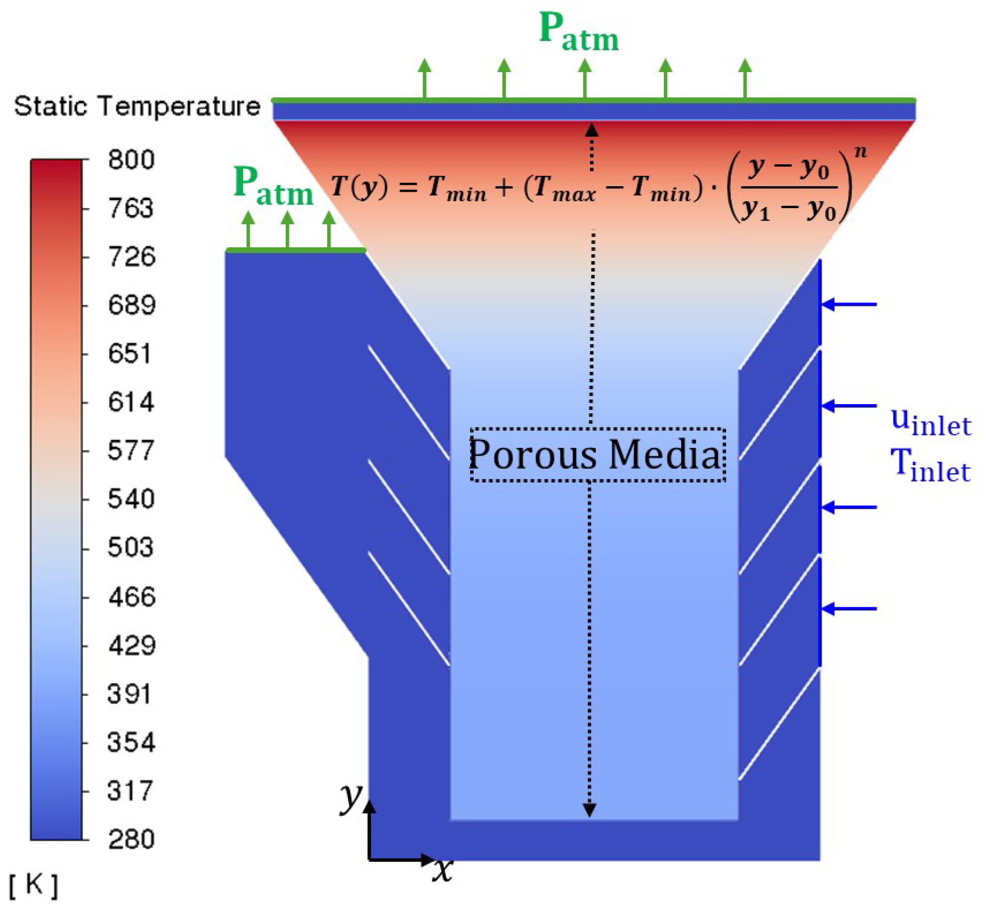
The circular-type vertical layer sinter cooler was measured to take approximately 600 s to complete one round after continuous-regime conditions. The discharge temperature of the material in the trolley was evaluated as 400 K and the material feed temperature as 800 K after each round under continuous conditions. Since the region in the inlet channel section of the trolley will cool faster than the upper region, the material temperature distribution is described by an exponential function, as shown in Equation (1).
T ( y ) = T m i n + ( T m a x T m i n ) · y y 0 y 1 y 0 n
Here, according to the independent variable y , y 0 represents the bottom vertical distance of the sinter relative to the set of axes, while y 1 represents the maximum distance of the sinter in the trolley. The term n represents the exponential coefficient. While the trolley continues to operate in a continuous regime, T m a x represents the maximum temperature of the sinter, while T m i n represents the temperature of the sinter in the discharge state, i.e., the minimum temperature.
As shown in Figure 2, the inlet boundary condition for a full-scale 2D problem domain with a width of 2900 mm and a height of 3606 mm is velocity, and the atmospheric pressure is defined as static pressure for both output boundaries. The air temperature discharged from the left side of the sinter cooling trolley ( T o u t 1 ) and the temperature discharged from the center of the trolley ( T o u t 2 ), which is a large air mass flow discharged from this area, were monitored instantaneously during the calculations. No slip condition and adiabatic assumptions are made for the fins and outer casing walls. The general transport equation in Equation (2) is solved as transient, since it is more reliable to follow the temperature of the outlet gas as a function of time in order to more accurately investigate the evaluation of the waste heat at the outlet. In the modeling of porous mediums, the temperature values of the gas phase are highly important in the evaluation of waste heat. Therefore, the governing equations have been modeled while taking into account the gas phase. Equations (2) and (3) represent the continuity and momentum equations of the gas phase.
( ρ g ) t + · ( ρ g V g ) = 0
( ρ g ) t + · ( ρ V g V g ) = P + · [ ( μ + μ T ) ( V g + ( V g ) T ) ] + S
ρ g is the density of the fluid (kg/ m 3 ), V g is the velocity vector of the flow (m/s), P is the pressure of cooling gas, μ is dynamic viscosity, μ T is the turbulent viscosity coefficient, and S is the source term. Turbulence, which represents the chaotic state occurring in the flow, is represented by the well-known standard k ε model with two equations. k is the turbulent kinetic energy and ε is the dissipation rate of the turbulent kinetic energy. The standard k ε turbulence model facilitates the near-wall interaction by assuming that the flow is completely turbulent. In the present study, a flow with a volumetric flow rate of approximately 111 m3/s at the inlet for each trolley is relatively chaotic as it enters the circular-type vertical layered sinter cooler. For such high flow rates, the standard k ε model is preferred in this study, assuming that the flow is fully turbulent. The RANS equations are solved with Ansys-FLUENT 2022 R1, a well-known commercial software using the finite volume method.
In the problem physics, the sinter material in the trolley is modeled using the porous medium approach. By adding Equation (4) to the source term in the momentum equations, the momentum transfer in that region can be modeled. Equation (4), expressed for the simple homogeneous porous medium case, contains the viscous resistance and inertial resistance terms [9,21].
Δ P L = 150 μ d p 2 ( 1 φ ) 2 φ 3 υ + 3.5 d p ( 1 φ ) φ 3 ρ υ 2 2
The second term in Equation (4) can be ignored if a laminar flow through a packed bed is to be modeled, which involves the Blake–Kozeny equation [21]. However, in this study, the whole equation is considered for turbulent flow conditions. In the equation, φ is the porosity and d p is the average diameter size of the particles. The viscous resistance coefficient (Equation (5)) is obtained from the first term and the inertial resistance coefficient (Equation (6)) is obtained from the second term.
1 α = 150 1 φ 2 d p 2 φ 3
C 2 = 3.5 1 φ d p φ 3
As seen in Equations (5) and (6), the porosity ( φ ) and average particle diameter ( d p ) have a significant effect on the evaluation of the waste heat obtained from the sinter material. Therefore, in this study, it is planned to examine both parameters at three different levels. According to the information provided by KARDEMİR Inc., the average particle size of the material is known to vary between 0 and 0.16 m. In addition, since the temperature of the fresh air sucked by the fan will vary according to the season, the inlet temperature parameter to represent the seasonal conditions at three different levels is considered. In order to compare the study parameters, base conditions were determined, each variable was evaluated within itself, and other parameters were kept constant as base parameters. To maintain physical relevance and align with existing research, key parameters were selected in accordance with values commonly reported in the literature [9,10,13,17]. The study parameters are shown in Table 1.
In the porous modeling process, the standard transport energy equation in Equation (7) is solved. Only the transient term and conduction flux expression undergo some modification. When expressing the conduction flux in the porous medium, the effective conductivity is taken into account and calculated using Equation (8). The thermal behavior (or thermal inertia) of the solid region in the porous medium is included in the transient term expression.
t φ ρ g E g + ( 1 φ ) ρ s E s + · V g ρ g E g + P = · k eff T i h i J i + τ ¯ ¯ · V g + S g h
k e f f = φ k g + 1 φ k s
φ is the porosity of the medium, k g is the thermal conductivity of the gas phase, and k s is the thermal conductivity of the solid phase. In Equation (7), E g represents the total fluid energy, while E s represents the total energy of the solid phase. The density ( ρ s = 1500 kg/m3) and thermal conductivity value ( k s = 2.87 W/mK [22]) of the sintered material are defined as constants, while the specific heat value, which changes with temperature, is calculated using temperature-dependent Equation (9) [22]. The dependent variable C s is defined within the solver using UDF code. In this study, the porous bed was modeled under the assumption of local thermal equilibrium (LTE) between the gas and solid phases, consistent with prior sinter cooling studies. Given the high surface area and effective heat transfer in the porous bed, LTE is considered acceptable for the present analysis, although future work may explore LTNE effects under strong thermal gradients.
C s = 337.03 · ( T s 273 ) 0.152
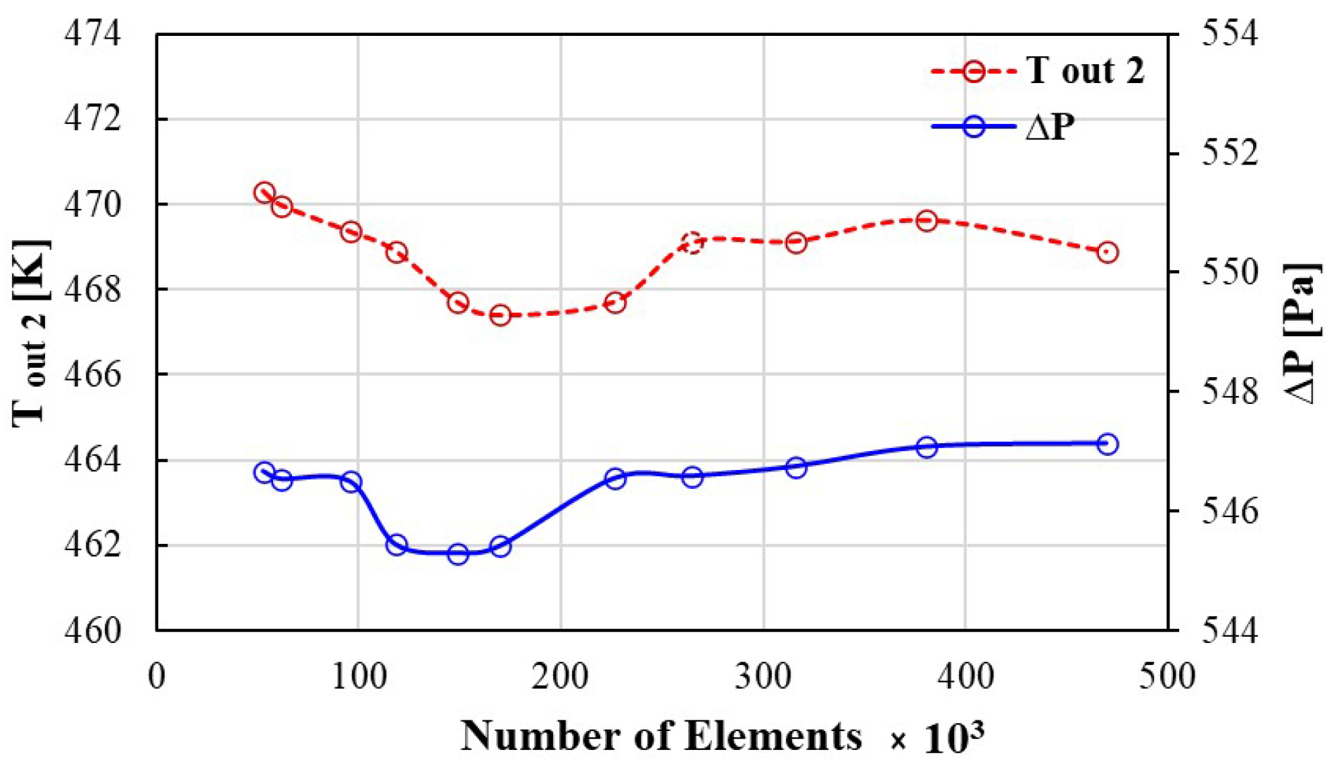
For the analysis of mesh independence of the numerical model created for the two-dimensional geometry in Figure 3, the mesh sizes were gradually reduced in the flow region and the number of elements was regularly increased. The number of elements was gradually increased across the entire domain, taking care not to leave the mesh coarse in porous region. Figure 4 shows a representative mesh view of the computational domain used in the study. The mass-weighted average static temperature was monitored in the outlet region from the center where the waste heat was evaluated. After 260 k elements, the change in the temperature of the outlet gas was found to be negligible. For the calculation time step Δ t for 1 s, the number of time steps required for the sinter trolley to complete one round in 600 s was calculated as 600. Approximately 20 iterations for each time step were sufficient for the solution to converge.

3. Results and Discussion

3.1. Comparison of the Numerical Model with Experimental Observations

Observations were made using temperature measuring probes that were either stationary or movable on the circular-type vertical layered sinter cooler shown in Figure 1. Here, measurements were planned using both the Eulerian and Lagrangian approaches. While the stationary probes took measurements from the same coordinates even when the trolleys were moving, the movable probe moved at the same speed as the trolley. After steady-state conditions were established in the circular sinter cooler, three rounds of data were recorded using the movable probe, and the average temperature distribution was obtained. The experiments were conducted using a K-type (NiCr-Ni) thermocouple. The measurement range was −200 to +1000 degrees Celsius. The accuracy was ±5 degrees Celsius for a range of +70 to +1000 degrees Celsius. For further details on the experimental work, see reference [18]. The obtained temperature data were then subjected to noise removal processing. The experimental data have been represented by a linear curve for a more meaningful interpretation. As seen in the temperature data shown in Figure 5, the experimentally measured outlet gas temperature has a more dominant cooling rate when compared to the numerical model. This situation is due to conditions that were neglected during the creation of the numerical model. These include the surfaces of the trolley in contact with the external atmosphere being defined as adiabatic and the presence of non-stationary airflow (wind) conditions in real-world external atmospheric conditions. Even though these assumptions were made to minimize computational costs, it can be said that the numerical model effectively represents the heat transfer gradient of the sintering cooling process.

3.2. Effect of Inlet Temperature

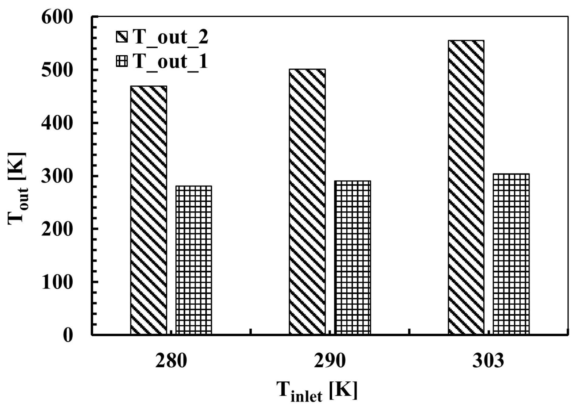
The waste heat temperature was determined for different inlet temperatures for the rotary sinter cooler. Calculations were carried out for two different air outlets. The inlet temperatures are parametrically evaluated for different seasonal conditions. Figure 6 shows the effect of different inlet air temperatures on two different outlet zones in a sinter rotary cooler. This analysis provides important insights into the efficiency of the cooling process and the potential for energy recovery. It is seen that the increase in inlet air temperature has a positive effect on the temperature in both outlet zones. When the inlet air temperature increases from 280 K to 303 K, T o u t 1 increases from approximately 280 K to 300 K, while T o u t 2 shows a significant increase from approximately 470 K to 560 K. A remarkable finding is that T o u t 2 temperatures are significantly higher than T o u t 1 temperatures at all inlet air temperatures. This indicates the presence of two separate air flow paths with different heat transfer dynamics inside the sinter rotary cooler. These temperature differences can have important consequences for the overall performance and energy efficiency of the sinter rotary cooler. The high-temperature T o u t 2 stream can be a valuable resource for waste heat recovery systems. Utilizing this hot air in preheating processes or power generation offers the potential to reduce the overall energy consumption of the system. On the other hand, the energy recovery potential of the low-temperature T o u t 1 stream is more limited.
Figure 7 presents the cooling curves of the temperature in the outlet region T o u t 2 of the sinter rotary cooler over time under three different constant inlet air temperatures (303 K, 290 K, 280 K). This outlet stream, which is initially at a high temperature, cools down with time and this cooling rate and the final temperature value depend on the applied inlet air temperature. At t = 0, the outlet temperature T o u t 2 starts at approximately the same high value (about 800 K) for all inlet air temperatures. This indicates that initially, the system is not thermally equilibrated, and the cooling zone of the sinter rotary cooler is approximately from wagon 1 to wagon 15. It may indicate that the hot material is still interacting with the cooling air. The slope of the curves represents the cooling rate. Although the cooling rates are relatively similar at the beginning, they become more pronounced for different inlet temperatures with time. Especially at a low inlet temperature (280 K), a decrease in the cooling rate is observed towards the end, which may indicate that the system is approaching thermal equilibrium or that heat transfer is becoming more difficult.
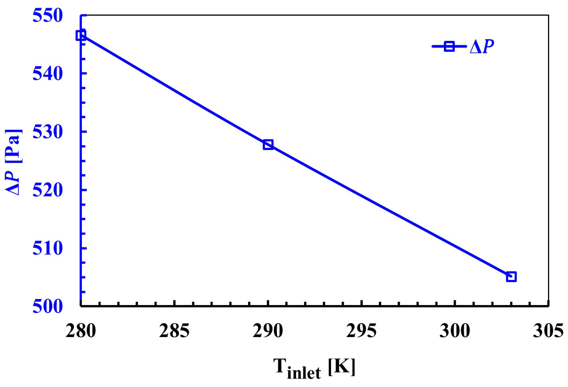
Figure 8 represents the effect of inlet temperature on pressure drop. The pressure drop exhibits a negative slope. This shows that the pressure drop in the system decreases as the inlet temperature increases. Pressure drop values for the inlet temperature are given. The pressure drop is approximately 547 Pa, 528 Pa, and 505 Pa for inlet temperatures 280 K, 290 K, and 303 K respectively. It is shown that the pressure drop decreases as the inlet air temperature increases in the sintered rotary cooler. This inverse relationship is a result of the complex fluid dynamics interactions that occur depending on the pore structure, boundary conditions, specific design, and operating conditions of the system.
The effect of inlet air temperature on the pressure loss in the system can be explained by changes in air density and viscosity. As the temperature increases, the density of the air decreases and its viscosity increases. Lower density means less mass flow in the same volume, resulting in lower resistance in the duct and porous medium. At the same time, increased viscosity contributes to less friction in the laminar sub-regions. These two effects combine to reduce the pressure loss, especially in turbulent regions. In addition, since the pressure loss in porous media according to the Darcy–Forchheimer equation depends on both velocity and fluid properties, the temperature-dependent change in fluid properties clearly affects the equations. Therefore, the pressure loss decrease observed in the system with increasing inlet air temperature is physically consistent.
The effect of inlet air temperature on system performance is multifaceted. While lower inlet temperatures allow for more efficient cooling of the sinter, they can potentially result in higher pressure drops. High pressure drops can negatively affect energy consumption by increasing the fan power requirement. On the other hand, high inlet temperatures reduce cooling efficiency, but can reduce the pressure drop in the system. Therefore, when determining the optimum operating conditions of the sinter rotary cooler, the balance between the desired cooling performance, energy consumption, and pressure losses in the system must be carefully evaluated.
The temperature distribution during the sinter cooling process is shown at different time intervals (150 s, 300 s, 450 s, and 600 s) as shown in Figure 9. The ambient air used in sinter cooling penetrates deep into the sinter material over time, creating a distinct thermal gradient from the surface to the core. The core temperature stays quite high at t = 150 s, and the cooling impact is restricted to the top region. The temperature gradient intensifies and the chilled zone spreads out sideways and downward as time increases to t = 300 s. A sizable amount of the sinter has cooled even more by t = 450 s, reaching low temperatures, suggesting efficient heat transfer brought on by convective air movement. The cooling phase is finally complete at t = 600 s, when a nearly uniform low-temperature area is seen. The cooling front’s advancement and the efficiency of forced convection in lowering the thermal energy within the sinter bed are both evident from the temperature contours and flow vectors. These findings highlight how the cooling process is time-dependent and how important airflow distribution is to achieving a consistent temperature drop throughout the sinter volume.
To determine the effects of inlet air temperature on fan power consumption, it is necessary to know the pressure loss and air flow rate in the system. The pressure loss occurring in the simulations applies to a single trolley. Since there are 16 trolleys in the existing facility, the calculations must be proportional accordingly. The fan power consumption is calculated as 60.6 kW, 58.6 kW, and 56.1 kW for 280 K, 290 K, and 303 K, respectively. Due to seasonal variations, the maximum possible difference in fan power consumption is 7.58%.

3.3. Effect of Porosity

Porosity is the ratio of the void volume of the sinter bed to the total volume, and it directly affects the interaction of the fluid with the solid phase. Increasing porosity can increase the number and continuity of fluid channels within the sinter bed. Figure 10 shows the changes for T o u t 1 and T o u t 2 as the porosity ratio ( φ ) in the sinter cooler increases from 0.3 to 0.5. As the porosity ratio increases, the outlet temperatures decrease. When the porosity ratio is 0.3, T o u t 2 is approximately 635 K, and when the porosity ratio increases to 0.5, T o u t 2 decreases to approximately 470 K. An increase of 66.7% in the porosity ratio (from 0.3 to 0.5) leads to a decrease of approximately 26% in the temperature T o u t 2 (from 635 K to 470 K). This significant decrease indicates that the heat transfer between the sinter bed and this stream increases with increasing porosity. Higher porosity allows the fluid to have a greater contact surface with the sinter particles, and therefore allows more heat exchange to take place. For porosity ratios of 0.3 and 0.5, the temperature T o u t 1 is approximately 293 K and 280 K, respectively. This allows a more efficient heat exchange by increasing the heat transfer surface area and turbulence, especially for the T o u t 2 stream in direct contact with the sinter particles. As a result, more heat is extracted from the sinter for the same amount of cooling air, and the T o u t 2 temperature is significantly reduced. These findings indicate that the porosity ratio is a critical parameter in sinter cooler design. In order to achieve the desired outlet temperatures and optimize cooling efficiency, porosity must be carefully controlled.
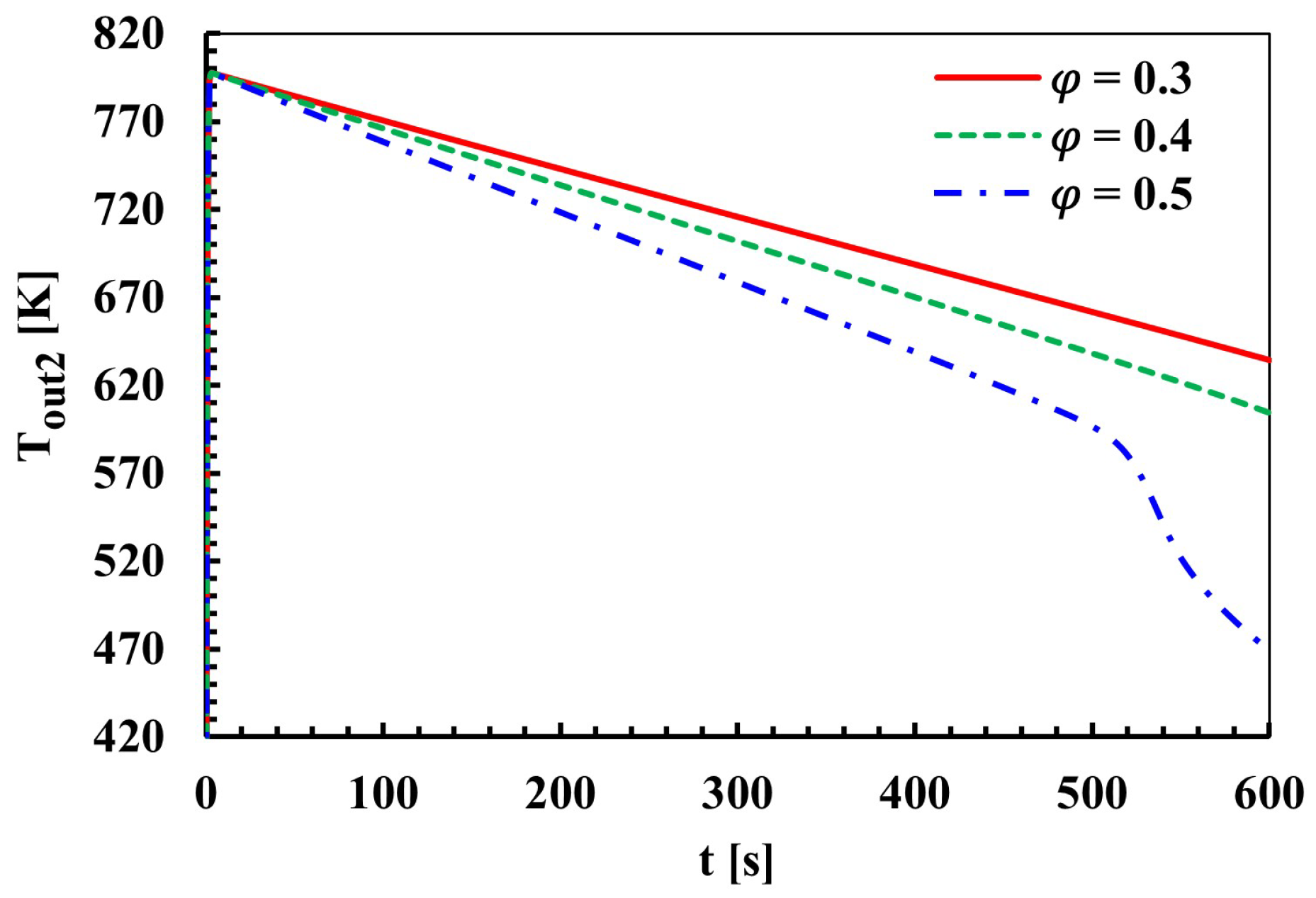
The impact of porosity ratios ( φ ) of 0.3, 0.4, and 0.5 on the temperature T o u t 2 in the sinter cooler and its time variation is depicted in Figure 11. At the lowest porosity value, the outlet temperature shows the slowest decrease with time. After 600 s, the outlet temperature is still at about 630 K. This suggests that at low porosity, the fluid makes less effective contact with the sinter material, and therefore heat transfer occurs more slowly. At the medium porosity value, the cooling rate is higher and the outlet temperature decreases to about 580 K at the end of 600 s. With an increase in porosity, it can be said that the fluid can better pass through the gaps between the sinter particles and provide more heat transfer by contacting more surfaces. At the highest porosity value, the fastest cooling is observed. Especially after about 500 s, the cooling rate increases significantly and the outlet temperature decreases to about 470 K at the end of 600 s. This shows that high porosity facilitates the flow of the fluid in the sinter bed, increases turbulence, and thus significantly improves heat transfer. Increasing porosity increases the amount of space between the sinter particles, facilitating the flow of coolant (air) through the bed. This leads to more contact of the fluid with the sinter surface, higher heat transfer coefficients, and therefore faster and more efficient cooling performance.
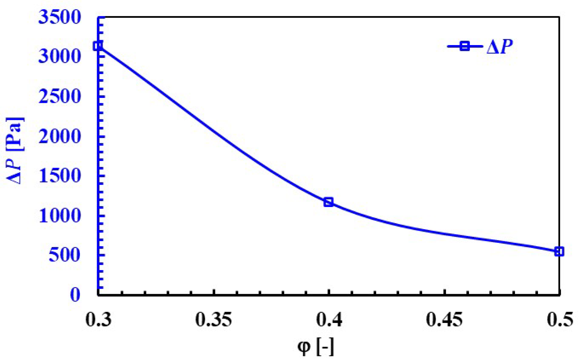
Figure 12 demonstrates the effect of porosity value on pressure drop. Clearly, as the porosity increases, the pressure drop decreases. This is in accordance with the general principle I mentioned earlier. Higher porosity means more voids or passageways that allow the fluid to pass through the material more easily, leading to less resistance and therefore a lower pressure drop. The porosity ratio values of 0.3, 0.4, and 0.5 are approximately 3150 Pa, 1150 Pa, and 550 Pa, respectively. A lower pressure drop means less pumping or fan power is required to move the fluid through the system. This reduces operating costs and improves the energy efficiency of the waste heat recovery system.
The effect of porosity on fan power consumption is also quite noteworthy. A low porosity value means there is little distance between materials, which is another important factor that will force air flow. The fan power consumption is calculated as 60.6 kW, 129.4 kW, and 347.1 kW for porosity values of 0.5, 0.4, and 0.3, respectively. These results clearly show that as porosity decreases, air passage resistance increases, and consequently, the fan consumes more power.

3.4. Effect of Particle Diameter

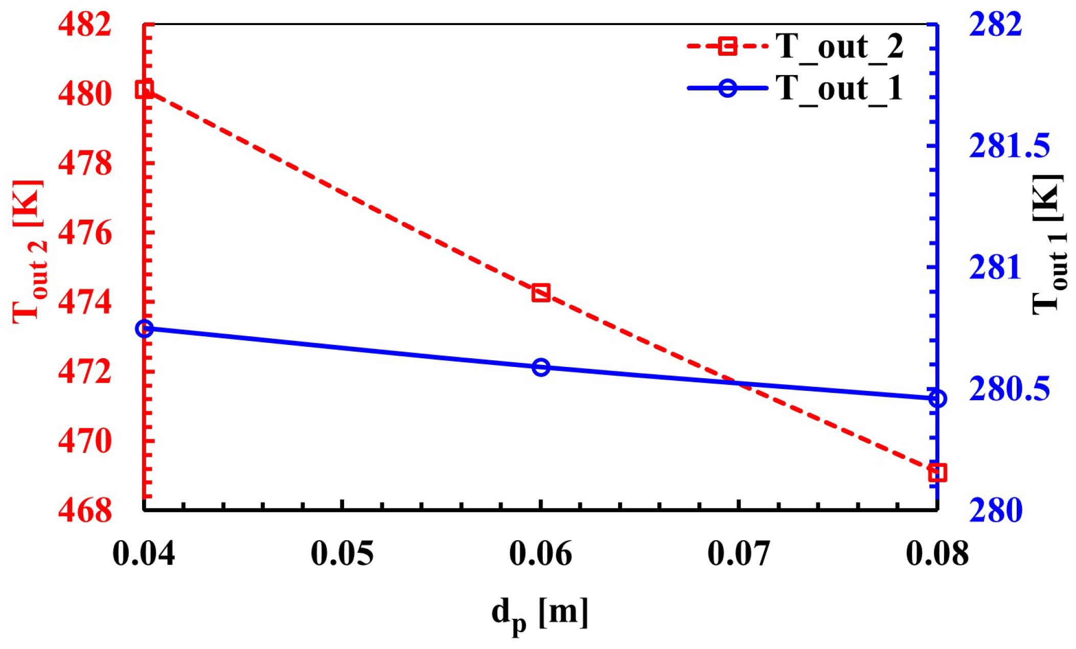
Figure 13 depicts the impact of variations in particle diameter on air outlet temperatures. It presents the variation in two different outlet temperatures, T o u t 1 and T o u t 2 , depending on the particle diameter ( d p ). It can be clearly seen that when the particle diameter increases from 0.04 m to 0.08 m, both outlet temperatures decrease. The air outlet temperature decreases from 281.7 K to approximately 280.4 K as the particle diameter increases from 0.04 m to 0.08 m. This decrease in T o u t 1 indicates that with the increase in particle diameter, more efficient heat transfer takes place in this region, and therefore the air cools more. The outlet temperature ( T o u t 2 ) decreases from 480.2 K to about 469.0 K as the particle diameter increases from 0.04 m to 0.08 m. The amount of decrease in T o u t 2 compared to T o u t 1 (about 11.2 K) is significantly greater than the amount of decrease in T o u t 1 (about 1.3 K). This indicates that particle diameter has a more dominant effect on the cooling performance associated with T o u t 2 . The decrease in outlet temperatures with increasing particle diameter is generally related to surface area and flow dynamics. Larger particles lead to an increase in the total surface area. It should be kept in mind that particle diameter is a critical design parameter when a certain temperature reduction is targeted in waste heat recovery systems. In both cases, it can be seen that temperatures decrease linearly with particle diameter.
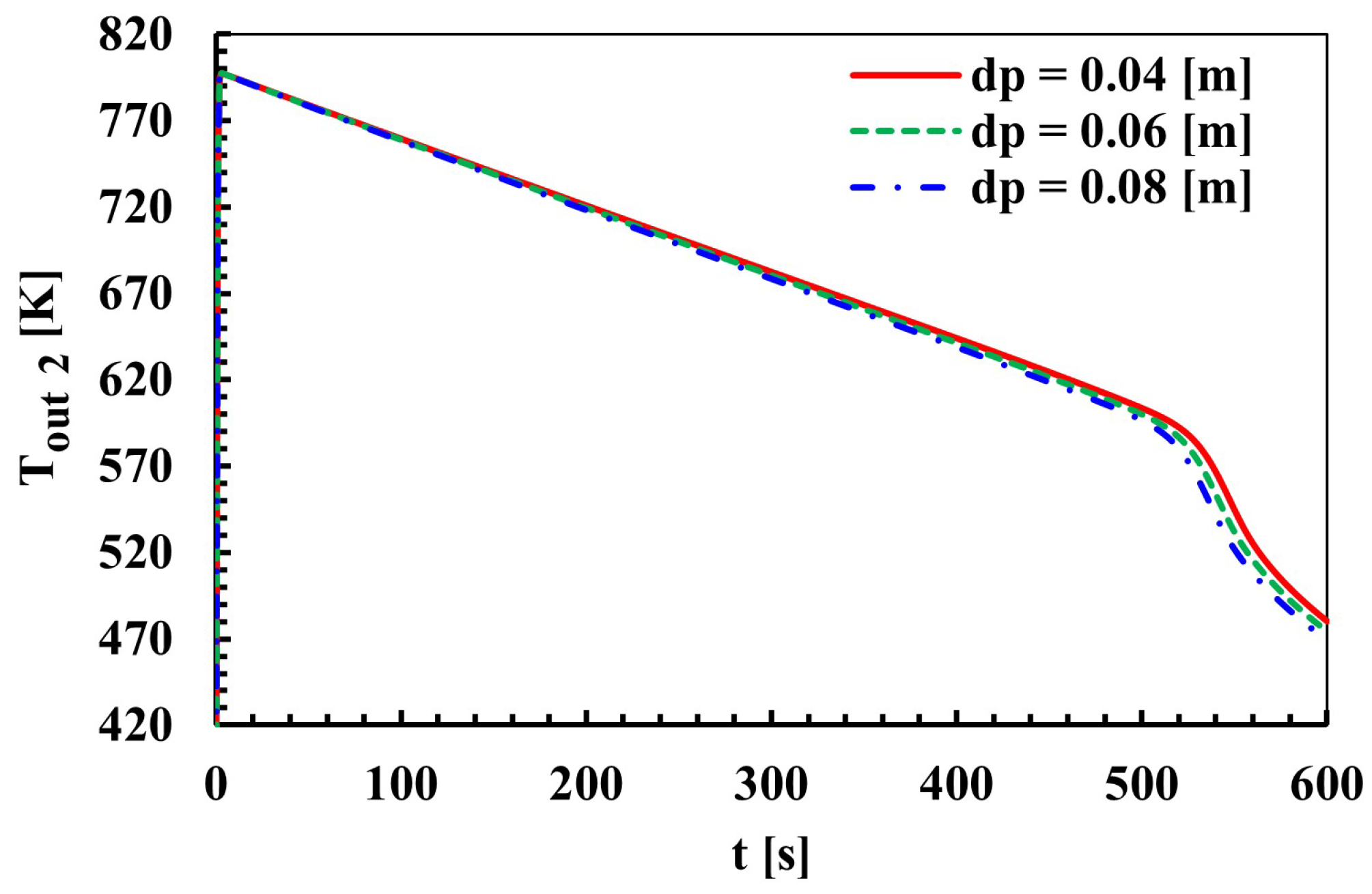
The time-dependent change in the outlet temperature T o u t 2 for various air particle sizes ( d p ) entering a sinter cooler at a fixed temperature is shown in Figure 14. The cooling curves reveal that the outlet temperature for all particle diameters starts at approximately 810 K at the beginning of the cooling process and decreases with time. During the first approximately 500 s, there is no significant difference between the outlet temperatures for the three different particle diameters. During this time, the temperature decreases with a linear trend from approximately 810 K to around 600 K. However, after about t = 500 s, the rate of decrease in the outlet temperature increases and the effect of particle diameters becomes more pronounced. Especially between t = 520 s and t = 560 s, the temperature decrease accelerates. In this critical region, the 0.04 m particle diameter tends to maintain higher temperature values than the others, while the lowest temperature values are reached for the 0.08 m diameter. The air temperature leaving the second zone of the cooler reaches the final values faster and lower as the particle diameter increases. These findings emphasize that particle diameter is an important parameter in sinter cooler design and optimization.
Figure 15 illustrates the effect of particle diameter on pressure drop in sinter cooling systems. It is clearly seen that the pressure drop decreases as the particle diameter increases from 0.04 m to 0.08 m. Specifically, the pressure drop with a particle diameter of 0.04 m was measured to be approximately 1000 Pa. When the particle diameter was increased to 0.06 m, the pressure drop decreased significantly to approximately 700 Pa. This indicates that a 50% increase in particle diameter (from 0.04 m to 0.06 m) results in a reduction in pressure drop of approximately 30%. After this point, the curve continues to decline with a less steep slope. When the particle diameter reached 0.08 m, the pressure drop decreased to approximately 550 Pa. The findings confirm that there is an inverse relationship between particle diameter and pressure loss during fluid flow. Larger particle diameters create wider flow channels in the porous medium, allowing the fluid to move with less resistance. This reduces friction losses and therefore pressure drop. Especially in applications such as porous structures, the effect of particle diameter on pressure drop is a critical parameter in terms of the energy efficiency and operating costs of the system. The findings emphasize that particle size should be carefully selected to achieve the optimum pressure drop at a given fluid flow rate.
One of the parameters that most affects fan power consumption in the facility is the size of the sintered material. As particle sizes decrease, the air flow will become more forced, which will directly affect fan power consumption. The fan power consumption is calculated as 60.6 kW, 77.7 kW, and 111.9 kW for particle sizes of 0.08 m, 0.06 m, and 0.04 m, respectively. Reducing the particle size from 0.08 to 0.06 results in an approximate 84.4% increase in fan power consumption.

3.5. Assessment of Results with General Data Ranges

The parameters and results obtained in this study are presented in Table 2 in comparison with similar studies in the literature. In the comparison made by considering basic variables such as the sinter inlet temperature, air flow rate, air inlet temperature, bed height, inner diameter, and outlet temperature, it is seen that the values of our study are largely consistent with the ranges in the literature. Despite having lower initial conditions, particularly in terms of sinter inlet temperature and air flow rate, the obtained air outlet temperatures are comparable to the values reported in the literature. This can be considered a positive indicator in terms of system efficiency. However, this assessment is presented from a very broad perspective. These compiled studies include a large number of variable parameters such as porosity, particle diameter, ambient conditions, etc. In general, the temperatures to which the air drops at the outlet and whether there is an achievable heat potential are discussed here to facilitate their tracking.

4. Conclusions

The determination of waste heat potential in sinter rotary coolers is important in terms of energy consumption. In this study, the waste heat recovery potential of rotary sinter coolers under varying operating conditions was investigated numerically and parametrically. Parametric studies were carried out according to the sinter inlet temperature depending on different ambient temperatures, porosities between particles, and particle diameters. Careful optimization of the parameters of the system reveals the need to improve the energy recovery performance of rotary-type sinter coolers. In particular, the separate evaluation of air flow paths with two different outlet zones allows for a more accurate analysis of the cooling efficiency and the potential recoverable waste heat. This approach provides a new perspective on the thermal characterization of the system and emphasizes the importance of regional analysis in the design process. The study obtained the following main findings.
  • The effect of sinter inlet air temperature on waste heat temperature was evaluated. When the inlet air temperature was increased from 280 K to 303 K, T o u t 2 increased by about 19% from 470 K to 560 K. For the same temperature increase, the pressure loss in the system decreased by 7.7% from approximately 547 Pa to 505 Pa. In addition, the temperature distribution inside the sinter cooler was analyzed. Temperature distributions are important in determining the cooling time and temperature distribution of the sinter.
  • When the porosity ratio was increased from 0.3 to 0.5, the T o u t 2 temperature decreased by 26% from about 635 K to 470 K. The pressure loss decreased by 82.5% from 3150 Pa to 550 Pa. This shows that porosity both increases cooling efficiency and reduces energy loss.
  • Particle diameter was analyzed and it was shown that larger particles provide lower pressure loss, but may limit heat transfer efficiency. The T o u t 2 zone outlet temperature decreased from approximately 480.2 K to 469.0 K with an increase in particle diameter from 0.04 m to 0.08 m. The pressure loss decreased from 1000 Pa to 550 Pa with a 45% decrease.
In practice, parameter optimization for rotary sinter coolers can be approached step by step. First, increase the porosity ( φ = 0.40–0.50) to significantly reduce pressure drop while maintaining cooling efficiency. Second, adjust the particle diameter ( d p = 0.06–0.08 m) to further lower fan power demand with only minor losses in outlet temperature. Third, consider seasonal inlet air temperature ( T i n l e t ) effects, where higher T i n l e t enhances waste heat quality ( T o u t 2 ), but may reduce final discharge cooling. Finally, prioritize T o u t 2 for waste heat recovery integration, while using T o u t 1 mainly for bulk cooling. These sequential adjustments provide a practical optimization path, ensuring efficient recovery with balanced fan energy requirements and compliance with discharge temperature limits.
In conclusion, this study contributes to the academic literature and provides a practical guide for implementing sustainable energy policies in the iron and steel industry. The data obtained can lead to the design of future waste heat recovery systems with lower energy loss, higher efficiency, and optimized fan power requirements.

Author Contributions

Conceptualization, İ.Z. and K.B.; methodology, İ.Z. and K.B.; software, İ.Z.; validation, İ.Z. and K.B.; data curation, İ.Z. and K.B.; writing—original draft preparation, İ.Z., K.B., N.Ö.A., H.İ.T., B.E. and Ş.U.; writing—review and editing, İ.Z., K.B., N.Ö.A., H.İ.T., B.E. and Ş.U. All authors have read and agreed to the published version of the manuscript.

Funding

This research was funded by the Scientific Research Project Unit of Zonguldak Bülent Ecevit University under project number 2024-77654622-01.

Institutional Review Board Statement

Not applicable.

Informed Consent Statement

Not applicable.

Data Availability Statement

The data presented in this study are available on request from the corresponding author.

Conflicts of Interest

Author Şeyma Ulukaya was employed by the company Karabük Iron Steel Industry Trade Co. Inc. The remaining authors declare that the research was conducted in the absence of any commercial or financial relationships that could be construed as a potential conflict of interest.

References

  1. Zhang, L.; Na, H.; Yuan, Y.; Sun, J.; Yang, Y.; Qiu, Z.; Che, Z.; Du, T. Integrated optimization for utilizing iron and steel industry’s waste heat with urban heating based on exergy analysis. Energy Convers. Manag. 2023, 295, 117593. [Google Scholar] [CrossRef]
  2. Cheng, Z.; Tan, Z.; Guo, Z.; Yang, J.; Wang, Q. Recent progress in sustainable and energy-efficient technologies for sinter production in the iron and steel industry. Renew. Sustain. Energy Rev. 2020, 131, 110034. [Google Scholar] [CrossRef]
  3. Feng, J.; Cheng, X.; Wang, H.; Zhao, L.; Wang, H.; Dong, H. Performance analysis and multi-objective optimization of organic Rankine cycle for low-grade sinter waste heat recovery. Case Stud. Therm. Eng. 2024, 53, 103915. [Google Scholar] [CrossRef]
  4. Liu, Y.; Yang, J.; Wang, J.; Ding, X.; Cheng, Z.; Wang, Q. Prediction, parametric analysis and bi-objective optimization of waste heat utilization in sinter cooling bed using evolutionary algorithm. Energy 2015, 90, 24–35. [Google Scholar] [CrossRef]
  5. Liu, Y.; Yang, J.; Cheng, Z.; Wang, J.; Wang, Q. Cost Benefits Analysis for Waste Heat Utilization in Sinter Cooling Bed. Chem. Eng. Trans. 2014, 39, 841–846. [Google Scholar] [CrossRef]
  6. Ja’fari, M.; Khan, M.I.; Al-Ghamdi, S.G.; Jaworski, A.J.; Asfand, F. Waste heat recovery in iron and steel industry using organic Rankine cycles. Chem. Eng. J. 2023, 477, 146925. [Google Scholar] [CrossRef]
  7. Zhang, S.; Wen, Z.; Liu, X.; Liu, X.; Wang, S.; Zhang, H. Experimental study on the permeability and resistance characteristics in the packed bed with the multi-size irregular particle applied in the sinter vertical waste heat recovery technology. Powder Technol. 2021, 384, 304–312. [Google Scholar] [CrossRef]
  8. Feng, J.; Dong, H.; Liu, J.; Liang, K.; Gao, J. Experimental study of gas flow characteristics in vertical tank for sinter waste heat recovery. Appl. Therm. Eng. 2015, 91, 73–79. [Google Scholar] [CrossRef]
  9. Zhang, X.; Chen, Z.; Zhang, J.; Ding, P.; Zhou, J. Simulation and optimization of waste heat recovery in sinter cooling process. Appl. Therm. Eng. 2013, 54, 7–15. [Google Scholar] [CrossRef]
  10. Tian, W.; Ni, B.; Jiang, C.; Wu, Z. Uncertainty analysis and optimization of sinter cooling process for waste heat recovery. Appl. Therm. Eng. 2019, 150, 111–120. [Google Scholar] [CrossRef]
  11. Zhang, S.; Zhao, L.; Feng, J.; Luo, X.; Dong, H. Thermal analysis of sinter vertical cooler based on waste heat recovery. Appl. Therm. Eng. 2019, 157, 113708. [Google Scholar] [CrossRef]
  12. Liu, Y.; Yang, J.; Wang, J.; Cheng, Z.; Wang, Q. Energy and exergy analysis for waste heat cascade utilization in sinter cooling bed. Energy 2014, 67, 370–380. [Google Scholar] [CrossRef]
  13. Feng, J.; Zhao, L.; Zhang, S.; Dong, H. Exergy analysis and parameter optimization of sinter cooling process in vertical moving bed for waste heat recovery. Appl. Therm. Eng. 2020, 175, 115370. [Google Scholar] [CrossRef]
  14. Feng, J.; Dong, H.; Gao, J.; Liu, J.; Liang, K. Experimental study of gas-solid overall heat transfer coefficient in vertical tank for sinter waste heat recovery. Appl. Therm. Eng. 2016, 95, 136–142. [Google Scholar] [CrossRef]
  15. Feng, J.; Dong, H.; Gao, J.; Li, H.; Liu, J. Numerical investigation of gas-solid heat transfer process in vertical tank for sinter waste heat recovery. Appl. Therm. Eng. 2016, 107, 135–143. [Google Scholar] [CrossRef]
  16. Salmon, F.; Ghadim, H.B.; Godin, A.; Haillot, D.; Veillere, A.; Lacanette, D.; Duquesne, M. Optimizing performance for cooling electronic components using innovative heterogeneous materials. Appl. Energy 2024, 362, 122983. [Google Scholar] [CrossRef]
  17. Zheng, Y.; Cai, J.; Dong, H.; Feng, J.; Liu, J. Experimental investigation of volumetric exergy transfer coefficient in vertical moving bed for sinter waste heat recovery. Energy 2019, 167, 428–439. [Google Scholar] [CrossRef]
  18. Erdoğan, B.; Topal, H.İ.; Aydın, N.Ö.; Bayramoğlu, K.; Zengin, İ.; Ulukaya, Ş. Integrated thermal and techno-economic analysis of waste heat recovery from sinter cooling in the iron-steel industry utilizing real data. Therm. Sci. Eng. Prog. 2025, 65, 103923. [Google Scholar] [CrossRef]
  19. Wang, W.; Li, S.; Zhen, J.; Guo, J.; Xu, W. Numerical study and orthogonal analysis of optimal performance parameters for vertical cooling of sintered ore. Sci. Rep. 2024, 14, 4904. [Google Scholar] [CrossRef]
  20. Feng, J.; Yan, Y.; Zhao, L.; Dong, H. Numerical study of gas–solid counterflow heat transfer in sinter vertical cooling furnace based on energy and exergy analysis. Appl. Therm. Eng. 2024, 244, 122773. [Google Scholar] [CrossRef]
  21. Ergun, S. Fluid Flow through Packed Columns. Chem. Eng. Prog. 1952, 48, 89–94. [Google Scholar]
  22. Cheng, Z.; Wang, H.; Feng, J.; Xia, Y.; Dong, H. Energy and Exergy Efficiency Analysis of Fluid Flow and Heat Transfer in Sinter Vertical Cooler. Energies 2021, 14, 4522. [Google Scholar] [CrossRef]
  23. Zhang, S.; Zhao, L.; Feng, J.; Luo, X.; Dong, H. Parameter optimization of gas–solid heat transfer process in sinter packed bed based on further exergy analysis. Chem. Eng. Res. Des. 2019, 146, 499–508. [Google Scholar] [CrossRef]
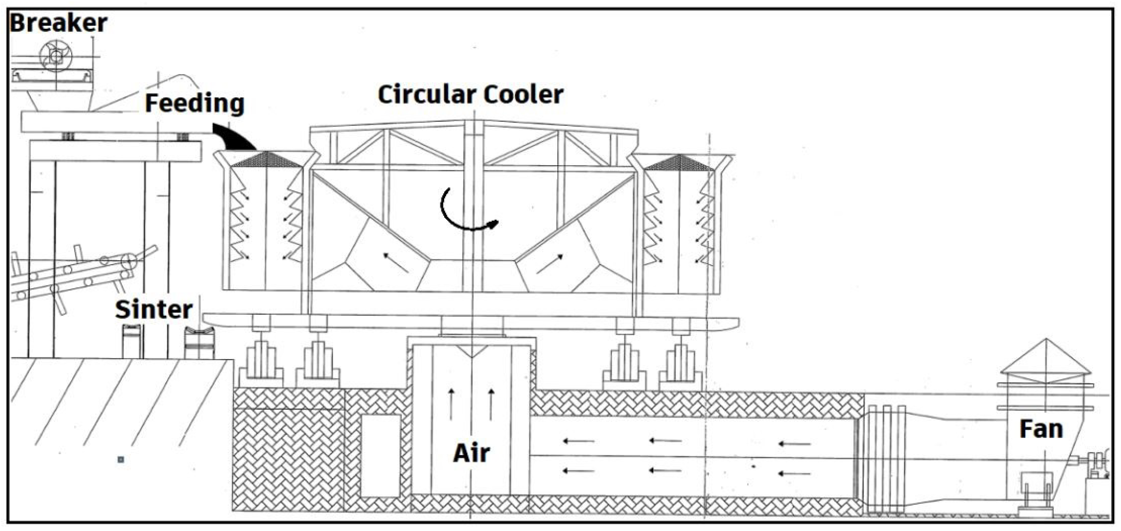
Figure 1. Circular type of vertical layer cooler for sinter cooling at Kardemir Inc.
Sustainability 17 08066 g001
Figure 2. Numerical model and boundary conditions.
Sustainability 17 08066 g002
Figure 3. Mesh independency study for sinter cooling.
Sustainability 17 08066 g003
Figure 4. Representative mesh view for rotary cooler model.
Sustainability 17 08066 g004
Figure 5. Temperature trends: comparison between simulation and experiment.
Sustainability 17 08066 g005
Figure 6. Changes in outlet air temperature depending on inlet air temperature.
Sustainability 17 08066 g006
Figure 7. Effect of inlet air temperature on cooling curves in sinter rotary cooler.
Sustainability 17 08066 g007
Figure 8. Effect of inlet air temperature on pressure drop in sinter rotary cooler.
Sustainability 17 08066 g008
Figure 9. Transient temperature and flow streamlines in sinter bed during cooling process.
Sustainability 17 08066 g009
Figure 10. Correlation of sinter cooler outlet temperatures with porosity ratio.
Sustainability 17 08066 g010
Figure 11. Effect of porosity ratio on time-dependent variation in outlet temperature.
Sustainability 17 08066 g011
Figure 12. Effect of inlet air temperature on pressure drop in sinter rotary cooler.
Sustainability 17 08066 g012
Figure 13. Variation in sinter cooler outlet temperatures with particle diameter.
Sustainability 17 08066 g013
Figure 14. Effect of particle diameter on time-dependent variation in outlet temperature.
Sustainability 17 08066 g014
Figure 15. Changes in particle diameter and pressure drop in sinter rotary cooler.
Sustainability 17 08066 g015
Table 1. Operating parameters for sinter cooling.
Operating ParametersSymbolLevel 1Level 2Level 3
Particle size [m] d p 0.040.060.08 *
Porosity [-] φ 0.30.40.5 *
Inlet air temperature [K] T inlet 280 *290303
* Base parameters.
Table 2. A comparison of the basic parameters of present study and some studies in the literature.
Sinter InletAir FlowAir InletSinter BedBed InnerAir Outlet
Temperature [K]Rate [kg/s]Temperature [K]Height [m]Diameter [m]Temperature [K]
Present study800130280–3033.610469–634
2020_Feng [13]973160–19029379750–800
2021_Cheng [22]993–11461902937 & 99727–867
2019_Zhang [23]1023380–4251.436.6678–637
2013_Zhang [9]1023404–4341.4–1.8525–760
Disclaimer/Publisher’s Note: The statements, opinions and data contained in all publications are solely those of the individual author(s) and contributor(s) and not of MDPI and/or the editor(s). MDPI and/or the editor(s) disclaim responsibility for any injury to people or property resulting from any ideas, methods, instructions or products referred to in the content.