1. Introduction
Environmental harm and global warming are caused by rapid industrialization and growing energy consumption. Energy systems must be developed in order to meet future demands for energy while trying to decrease dependence on fossil fuels and reduce greenhouse gas emissions. According to research, low-grade heat accounts for more than half of all industrial heat production, and this heat is lost as thermal pollution [
1]. Developing renewable energy and improving energy efficiency are potential solutions to thermal pollution. Since most renewable energies produce low-grade heat, power generation is an appropriate use [
2]. A power cycle refers to the sequence of processes through which a power system generates and delivers electrical energy. It typically involves a fuel supply (e.g., coal, gas, nuclear, wind, or solar), a prime mover (such as a turbine), a generator, a transmission system, and a load (the end user). Using working fluids to transfer heat and generate mechanical energy, each cycle has unique characteristics, efficiencies, and is suited to specific energy sources and applications. Common power cycles include the Rankine, Brayton, Stirling, Otto, Diesel, and organic Rankine cycles, each with distinct characteristics and efficiencies influenced by factors like fuel type, design, and operating conditions. Beyond thermodynamic cycles, electrical power cycles—like battery charging and discharging—also play a role. Understanding these cycles is vital for improving efficiency, reducing environmental impact, and developing cost-effective, sustainable energy systems [
3,
4,
5,
6]. The Carnot cycle is a theoretical thermodynamic model that represents the most efficient possible method of converting heat into work. It consists of four reversible processes: two isothermal (constant temperature) and two adiabatic (no heat exchange), operating between a high-temperature and a low-temperature heat reservoir. The cycle involves a working gas undergoing expansion and compression, absorbing heat from the hot reservoir and releasing it to the cold one. Its efficiency, known as Carnot efficiency, depends solely on the temperatures of the reservoirs and sets the upper limit for real-world heat engine performance. Though idealized and not achievable in practice due to irreversibilities, the Carnot cycle is crucial for understanding thermodynamic principles and evaluating the performance of engines and refrigerators. It can also be reversed to model refrigeration, with efficiency measured by the coefficient of performance (COP). Represented on a pressure-volume (P-V) diagram, the area enclosed shows the net work done. Proposed by Sadi Carnot in 1824, the cycle remains a foundational concept in thermodynamics [
7,
8]. The Brayton cycle, also known as the Joule cycle, is a thermodynamic cycle widely used in air conditioning and gas systems. Four main stages usually occur: isentropic compression, constant-pressure heat addition, isentropic expansion, and constant-pressure heat rejection. In gas turbines, air is compressed, mixed with fuel, and combusted, then expanded through a turbine to produce work. The cycle models continuous combustion and can be modified with intercooling, reheating, and regeneration to improve efficiency. In air conditioning, a similar process called the vapor compression cycle uses refrigerants instead of air. The Brayton cycle helps to analyze engine performance under varying conditions and serves as a key model for improving thermal efficiency [
7,
9]. Thermodynamic processes like the Rankine cycle are frequently employed in steam power plants to produce electricity. The condenser, turbine, boiler, and pump are its four primary parts. High-pressure water is heated in a boiler to create steam, which expands through a turbine to produce electricity. The steam is subsequently recirculated after condensing back into water. To provide insights into plant efficiency, the cycle named after William Rankine models the continuous conversion of water to steam and back. Superheating, reheating, and binary cycles are examples of improvements that can boost efficiency by increasing the temperature of the steam or recovering more heat. A flexible model for energy conversion, the Rankine cycle is also utilized in heating, cooling, and geothermal systems [
10,
11].
One of the many well-established methods for low and medium temperature heat recovery for power generation is the organic Rankine cycle (ORC). The primary advantage of ORC is its potential for successful application in a range of sectors, such as biomass combustion, solar desalination, and geothermal energy. When gas turbine exhaust gases are at low temperatures, it is also very helpful. ORC’s value offer is especially appealing due to its high levels of dependability and flexibility [
12]. To allow energy recovery at lower temperatures and pressures, an organic working fluid is used in the traditional Rankine Cycle. This reduces turbine corrosion risk and overall system costs. The ORC system features a simplified layout, often with a heat exchanger that preheats, vaporizes, and superheats the working fluid, eliminating the need for water treatment [
13]. Based on the working fluid’s pressure in relation to its critical point, ORC systems can be classified as subcritical, transcritical, or supercritical. Geothermal and biomass heat sources are well-suited for subcritical and transcritical systems, whereas higher-temperature sources like industrial waste heat are better suited for supercritical systems. ORC is used in waste heat recovery systems, geothermal, biomass, and solar energy [
14]. A low boiling point, nonflammability, environmental safety, and good thermodynamic performance are all essential when choosing an organic fluid. Implementation is also impacted by system sensitivity to environmental factors, scalability, and complexity. Notwithstanding these difficulties, ORC technology holds promise for generating electricity from waste heat and renewable energy sources, aiding in the shift to low-carbon energy. The goals of ongoing research are to lower system costs, increase efficiency, and optimize fluid selection [
15].
The Sun and every other celestial body that orbits it, held together by gravity, make up the solar system. Photovoltaic systems, which use solar panels to directly convert sunlight into electricity, are among the most promising renewable energy technologies. These panels can be mounted on the ground, poles, carports, or shaded structures, though they are most frequently placed on rooftops for the best sun exposure. In addition to providing environmental advantages, photovoltaic systems are eligible for federal and state tax breaks [
16]. Building-integrated photovoltaics (BIPV) offer energy savings, reduced construction costs, and esthetic value by fusing solar technology with building materials. In addition to lowering pollution, BIPV systems are frequently incorporated into new construction or retrofit plans. Multiple solar cells, which are tiny devices that transform sunlight into electricity, make up a solar panel. A solar panel, which is made up of numerous cells, produces more usable electricity than a single cell, which only produces a small amount of power. An array, which is frequently seen on rooftops, is made up of several panels joined together. Scalable solar energy solutions are made possible by this modular configuration, which also boosts power output [
17]. The ancient Greeks and other civilizations have been using solar energy to heat their homes for centuries. In 1767, Swiss physicist Horace Benedict de Saussure constructed the first solar collector, which is regarded as the first solar oven. It was an insulated box that could reach 110 °C. Alexandre Edmond Becquerel discovered the photovoltaic effect in 1839 when he observed that exposure to light increased electric current. Although early models had issues with heat retention, solar water heaters were widely used by the 19th century. Back in 1909, William J. Bailey created the groundwork for contemporary solar thermal systems by improving the design by separating the water tank and solar collector [
18]. Solar energy is a clean, renewable, and limitless source of power that produces no emissions or pollution during generation. In contrast to fossil fuels, solar energy is environmentally benign and sustainable. It is produced by technologies that fall into one of two categories: active or passive. Mechanical devices are used in active solar energy systems, like photovoltaic panels and solar thermal systems, to transform sunlight into heat or electricity. In contrast, passive systems use natural features such as windows, orientation, and ventilation, as well as building design, to absorb and disperse solar heat without the need for mechanical assistance [
19]. The solar organic Rankine cycle (ORC) is a renewable energy technology that uses a working fluid, usually an organic compound with a low boiling point, that is heated by solar collectors, much like the traditional Rankine cycle. Following vaporization, the fluid powers a turbine, generating mechanical energy that is transformed into electrical power. Solar ORC systems are particularly well-suited for off-grid communities, remote locations, and industrial or agricultural settings that require dependable, environmentally friendly energy [
20,
21]. Because of the working fluid’s capacity to store heat, these systems are especially efficient in areas with high solar radiation levels and can function even in the absence of direct sunlight. Solar ORC can operate at greater temperatures and continue to function in a variety of weather situations, in contrast to photovoltaic panels, which immediately convert sunlight into electricity. To increase energy reliability, solar ORC technology is now being combined with other renewable energy sources like wind or hydro. Applications include desalinating seawater, supplying electricity to isolated communities, and assisting with industrial processes. Solar ORC systems are becoming more widely available and more effective as research advances and costs continue to decline. Because of this technology’s potential to reduce greenhouse gas emissions and aid in the transition to sustainable energy, governments and organizations throughout the world are investing in it more and more. With ongoing development, solar ORC systems are expected to play a key role in the global transition to clean and dependable energy solutions [
22,
23,
24].
One of the main challenges in designing solar energy equipment is the low flux density of sunlight, which requires large surface areas to collect sufficient energy. Larger surfaces increase installation costs, making energy delivery more expensive. For example, on a clear day with the sun directly overhead, 10 m
2 of surface can theoretically collect about 2 kW of energy with 70% collection and 30% conversion efficiency. However, factors like cloud cover and sun position reduce this in practice. Solar energy reaching Earth includes both direct sunlight and diffuse radiation scattered by the sky. On cloudy days, direct energy decreases while diffuse energy increases, sometimes reaching up to 400 W/m
2. Thick clouds reduce the total radiation more than thin ones by reflecting more energy back into space [
25]. Another limitation is the geographic distribution of solar energy, as high irradiance is often found in remote regions far from industrial centers, requiring energy transmission infrastructure. The highest average annual irradiance, about 300 W/m
2, is found near the Red Sea. Globally, the most solar-rich areas—such as parts of Saudi Arabia, central Australia, South Africa, and India—are often flat, arid deserts unsuitable for agriculture but ideal for solar installations. While equatorial regions have high cloud cover, reducing average irradiance, their seasonal variation is minimal compared to northern climates. These regions offer strong potential for solar electricity generation despite practical and logistical challenges [
26]. Types of solar panels vary mainly in the purity and structure of their silicon, which affects their efficiency in converting sunlight into electricity. The more perfectly arranged the silicon molecules, the higher the efficiency. There are five main types of solar panels, and the best choice depends on your project’s needs, not just cost, which tends to rise with efficiency.
Monocrystalline panels are made from a single, pure silicon crystal sliced into wafers. They are the most efficient and space-saving, but also the most expensive. Polycrystalline panels, created by melting and re-casting multiple silicon fragments, are less efficient but more affordable and common in residential setups. Amorphous silicon panels, also known as thin-film, are the least expensive and least efficient. They consist of a non-crystalline silicon layer applied to surfaces and are valued for their flexibility and low cost [
27]. Solar thermal systems, sometimes referred to as solar heating systems, use sunlight to produce heat for cooking, water heating, and space heating. Solar collectors, which are mounted on rooftops, heat liquid in tubes before storing it in a tank. These systems transfer thermal energy as opposed to electrical energy, like photovoltaic panels do. About 30% of homes in Mediterranean nations have solar water heaters. For efficiency and beauty, building-integrated solar thermal (BIST) systems integrate with the architecture. Active systems, which use pumps and controls, and passive systems, which depend on natural circulation and are more prevalent in the winter, are the two primary types [
28]. A solar collector captures solar energy radiated by the sun to manufacture electricity or produce heat. There are different kinds of solar collectors, such as thermal collectors, which heat liquids or air, and electrical PV panels, which convert sunlight into electricity using silicon-based cells. Different types of thermal collectors include flat plate, concentrating, and evacuated tube collectors. Combining PV and thermal technologies makes hybrid solar collectors that produce both heat and electric power. The efficiency and cost-effectiveness of solar appliances, coupled with their ability to generate renewable energy, have resulted in widespread adoption of solar appliances in homes, businesses, and industries [
29,
30]. One very effective solar thermal method of water or other fluid heating is the use of evacuated tube collectors. These are glass tubes sealed in a vacuum with metal absorber plates that efficiently transfer solar heat to a fluid while reducing heat loss. Because of their insulation and ability to retain heat, these collectors perform well in cold, clear, or hot climates. Some uses of collectors can include air conditioning, space heating, and domestic water heating for residential and commercial buildings. Thanks to robust materials like copper and borosilicate glass, they have high efficiency, modularity, and long lifetimes, which means they need to be well-installed and serviced because they are relatively expensive to purchase initially and may be destroyed by harsh weather [
31,
32].
The aim of this paper is to create a thermodynamic performance analysis and design an organic Rankine cycle (ORC) driven by solar energy for power generation by investigating five different types of systems for ORC. A basic Organic Rankine cycle (ORC), a recuperative Organic Rankine cycle (ORC), a regenerative Organic Rankine cycle (ORC), a recuperative–regenerative (RR) organic Rankine cycle (ORC), and a basic organic Rankine cycle (ORC) with reheat. Five different types of working fluids, R-11, R-123, R-141b, n-Pentane, and toluene, will be used in order to study the installation of the solar energy system and select the best system to power this cycle. Additionally, the effects of altering the different parameters that affect the cycle’s efficiency and power output are studied and analyzed.
2. System Setup
The major components of a solar ORC system play critical roles in the efficiency and performance of the system. Every component plays a major role in contributing to the cycle, from absorbing and transferring solar energy to converting it into electricity. It is extremely crucial to understand the major components of a solar ORC system while designing, building, and operating an efficient and reliable system. We will present an overview of the major components of a solar ORC system, starting with a solar collector, which is one of the important components that transform solar power into heat energy, that generates electricity in the ORC system. A heat exchanger moves heat from the solar collectors to the working fluid. To transfer heat and produce electricity, the ORC system uses an organic working fluid. Its ability to function at low pressures and temperatures makes it a desirable choice. In the evaporator, heat from the solar collectors is used to evaporate the working fluid. A turbine produces electricity by burning a high-pressure vaporized working fluid to power a generator. When heat is released to a cooling medium, like air or water, the working fluid condenses back into a liquid state in the condenser. The ORC system’s working fluid is circulated by means of a pump. A control system is important, which keeps an eye on and controls how the ORC system operates to make sure it is operating effectively and efficiently. A generator that transforms the turbine’s mechanical energy into electrical energy, and finally, a cooling tower is used to eliminate extra heat from the condenser’s cooling medium. Also, there are some additional components that may be included depending on the specific application and requirements of the ORC system, which can enhance the performance and reliability. This includes a storage tank that stores hot water or other fluids to be used as a heat source for the ORC system during periods when solar energy is not available. A heat exchanger for thermal storage or heat rejection, which either transfers heat from the stored fluid to the working fluid in the system or transfers heat from the working fluid to a cooling medium, such as air or water, during the condensation process. An expansion valve that reduces the pressure of the working fluid before it enters the evaporator, allowing it to vaporize at a lower temperature. A heat recovery system recovers waste heat from the ORC system and uses it for other applications, such as space heating or hot water production. Finally, an auxiliary heating system provides additional heat to the system when solar energy is not sufficient, such as during periods of low sunlight or at night. This paper investigates five different systems, as shown in
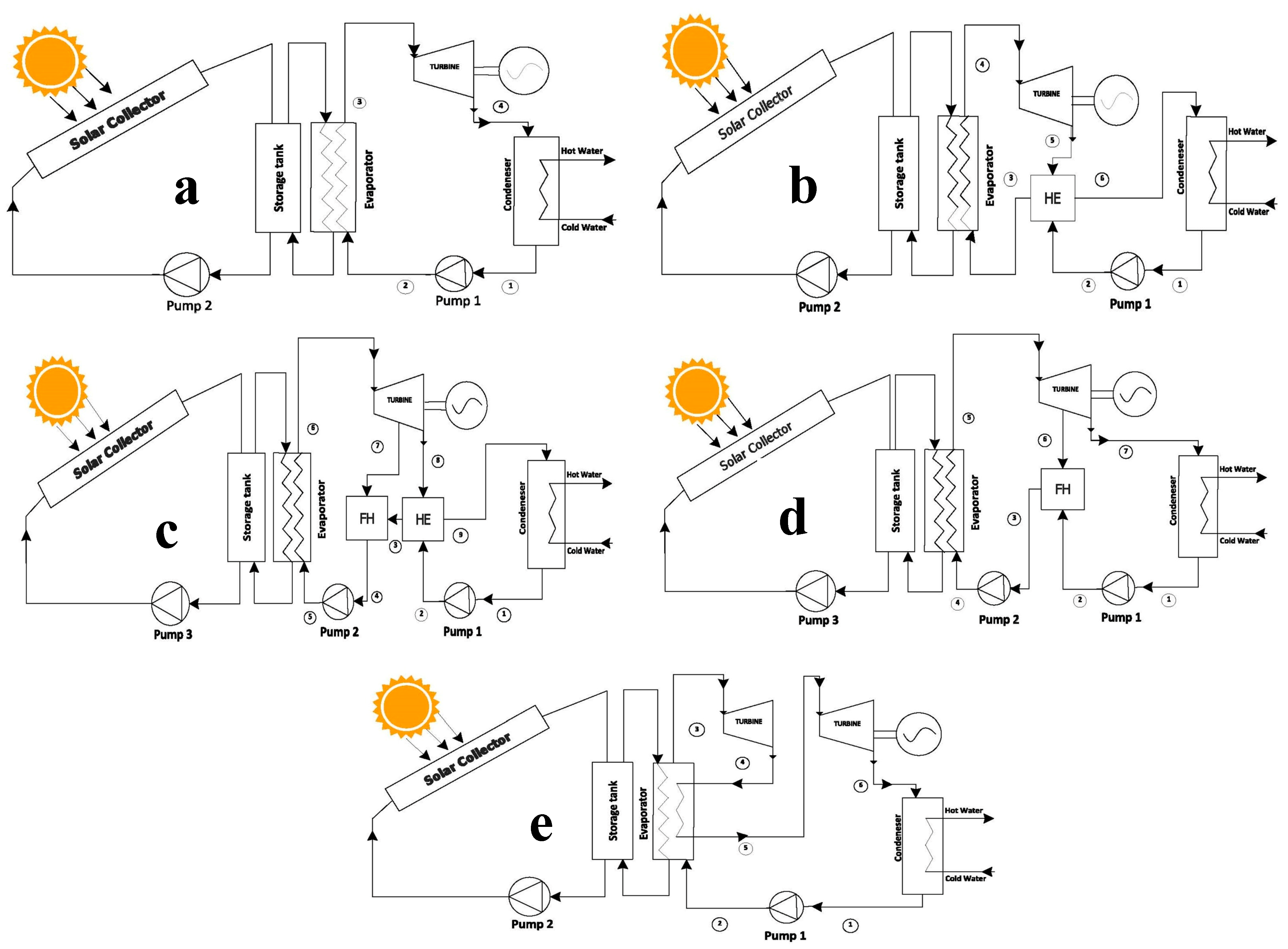
Figure 1, to focus on improving efficiency for power generation by optimizing the use of waste heat to increase the overall efficiency of the system.
A basic ORC system,
Figure 1a, operates in a closed loop, where the working fluid is continuously cycled through the system. The working fluid enters the pump as a saturated liquid and is isentropically compressed to the operating pressure of the evaporator. This isentropic compression process causes a slight increase in the temperature of the working fluid due to a slight decrease in the specific volume. Working fluid enters the evaporator as a compressed liquid and exits as superheated steam. The superheated steam enters a turbine where it expands isentropically to do work. During this process of steam entering the condenser, the pressure and temperature of the steam are reduced. In this state, the vapor is typically a high-quality saturated liquid-vapor mixture. Steam is condensed at a constant pressure in a condenser. The vapor exits the condenser as a saturated liquid and enters the pump to complete the cycle.
A recuperative ORC system,
Figure 1b, uses heat exchangers to recover more heat, which is placed after the turbine outlet and before the evaporator. By transferring heat from the hot working fluid exiting the turbine, the heat exchanger preheats the compressed working fluid before it enters the evaporator. One of the advantages of this system is the ability to generate electricity from waste heat sources that would otherwise be lost, improving overall energy efficiency and reducing greenhouse gas emissions.
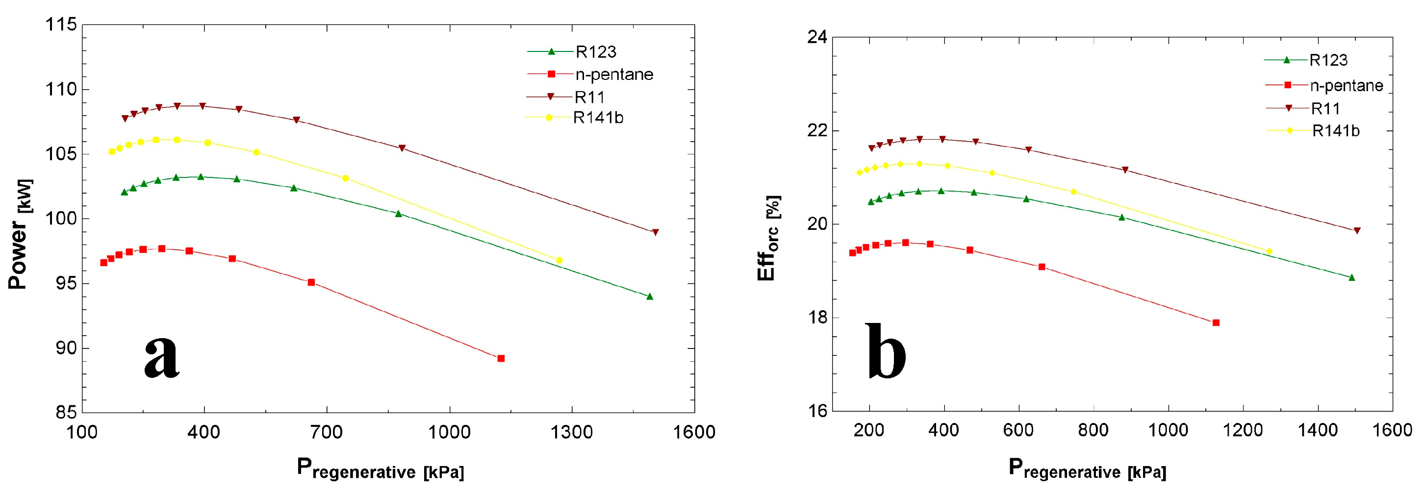
A regenerative ORC system,
Figure 1c, is widely used to increase the thermal efficiency of the Rankine cycle. This process uses steam extracted from a steam turbine to raise the temperature of the incoming working fluid before it enters the evaporator. The thermal efficiency of the regenerated Rankine cycle has been shown to increase with the number of feed heaters. However, adding more feed heaters reduces the efficiency gain.
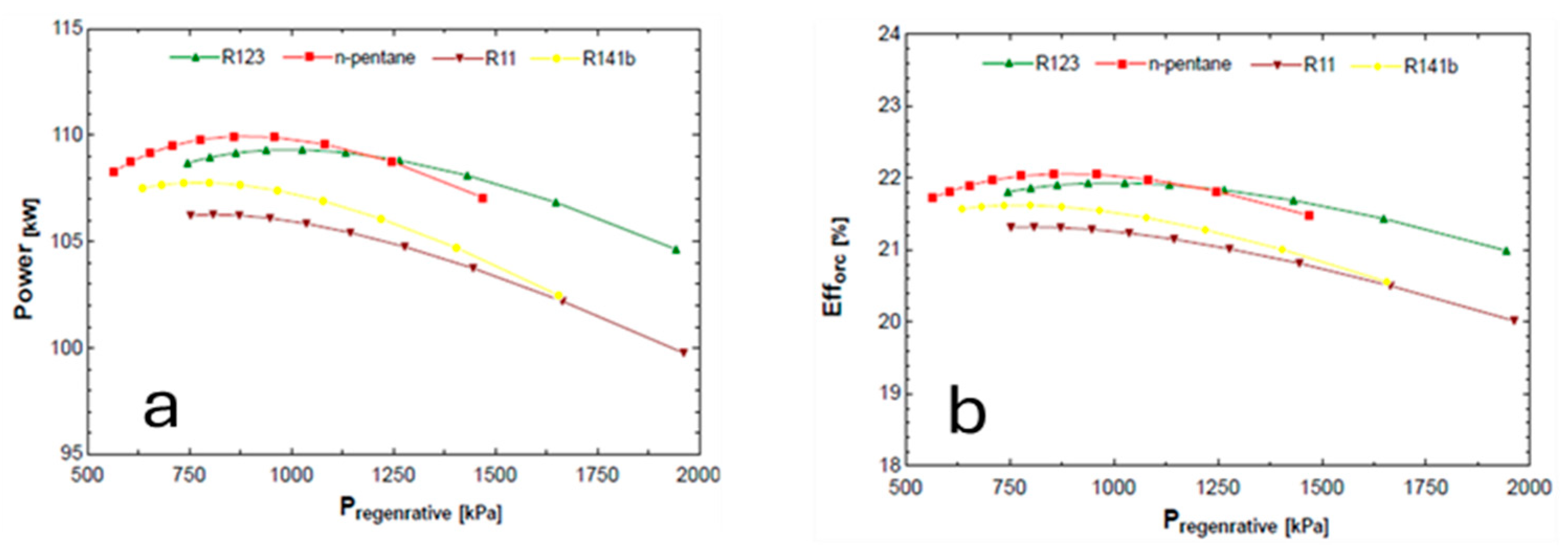
A recuperative–regenerative ORC,
Figure 1d, combines the advantages of both recuperative and regenerative ORC systems. It works by using a combination of heat exchangers and a built-in feed heater cycle. The steam extracted from the turbine is mixed with the supplied working medium and discharged from the pump. Ideally, the combination exits the heater as a saturated liquid at the heater pressure. The figure shows the modified ORC schematic incorporating both regeneration and turbine extraction. Overall, the recuperative–regenerative ORC system is a promising solution for waste heat recovery and can contribute to improving energy efficiency.
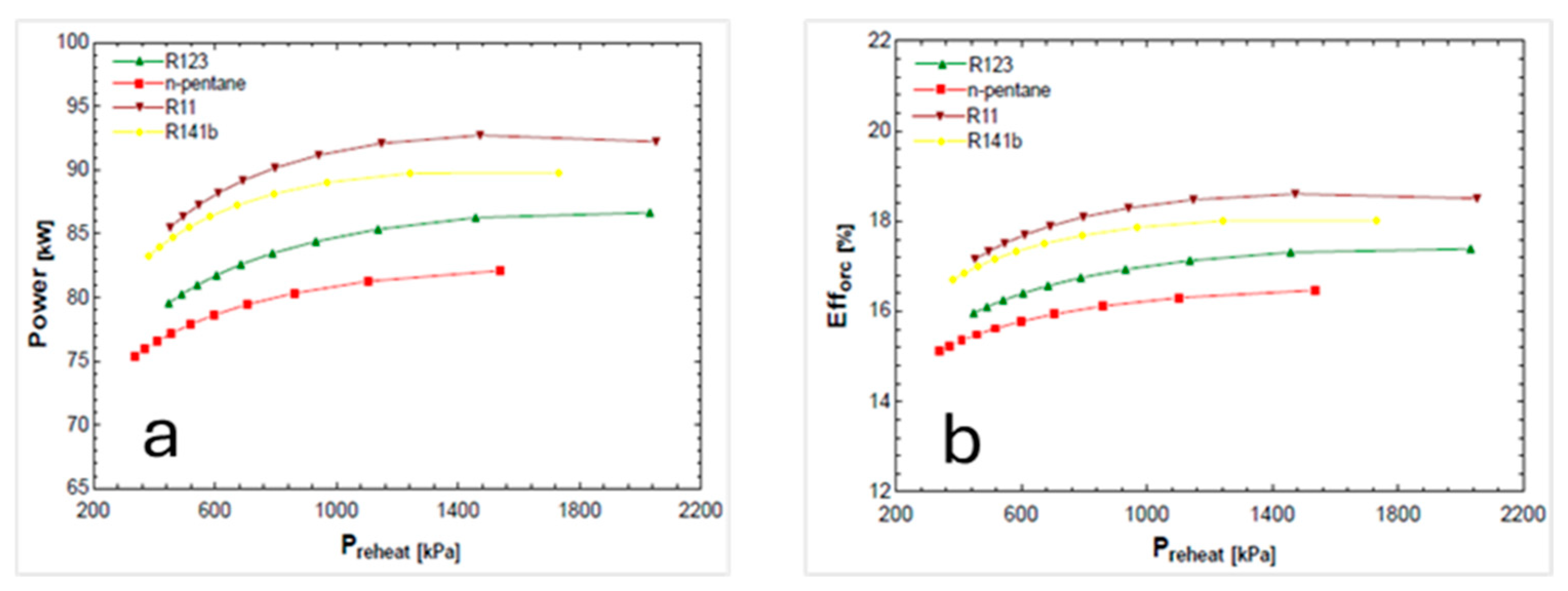
A basic ORC with reheat,
Figure 1e, is a system that incorporates a reheat process by increasing the evaporator pressure. To avoid moisture build-up in the steam exiting the turbine, the steam is expanded to intermediate pressure and reheated in the evaporator. After that, an expansion process takes place in the turbines where the steam is expanded in the high-pressure turbine to an intermediate pressure and returned to the evaporator. The steam is reheated and then sent to the low-pressure turbine, where it expands until it reaches the pressure of the condenser. The basic ORC with reheat system is often used in applications where there is a low-grade heat source available, such as geothermal and waste heat recovery systems. It can be particularly effective in applications where the temperature of the waste heat source is low, as the reheating process can help to increase the overall efficiency of the cycle.
The selection of the best working fluid is one of the steps in configuring an ORC system and can be quite challenging to perform. It can influence slightly, moderately, or even drastically impact the system’s efficiency and performance, therefore demanding careful consideration of the application’s particular needs. These factors include the thermodynamic properties of the fluid, needs for the heat source temperature, and the power output expectations of the system. The environmental consequences of the fluids, such as ozone layer damage and potential greenhouse gas emissions, must also be accounted for. A number of these characteristics were evaluated for the working fluids of the system. Firstly, to guarantee effective heat transfer, the boiling point of the working fluid must be below the source of heat. For adequate power production, the working fluid’s vapor pressure must be sufficiently high, but it must avoid so much excess as to pose operational safety concerns. Rather, it is best when focused on thermal stability, wherein the fluid is properly contained and protected from degrading or breaking down at elevated temperatures. Additional requirements dictate the heat capacity, where it is essential to enable better heat transfer, in addition to viscosity, which needs to be maintained at low levels for proper and effective flow through the system. The working fluid must not be toxic, highly flammable, or pose a danger to the environment and people. It should be available and compatible with the materials and components used in the system, and corrosive.
Different fluids have been chosen after consideration, fluorocarbon refrigerants such as R-11, R-123, and R-141b, which have high thermodynamic efficiency and low environmental impact. Hydrocarbons such as n-pentane have a higher boiling point and lower vapor pressure. Aromatic compounds such as toluene have high thermal stability and low environmental impact.
Table 1 shows some of the physical and environmental properties of the individual working fluids. R-11 has a high boiling point, which is suitable for high-temperature heat sources and proven to be highly efficient in ORC systems due to its high molecular weight. On the other hand, it has a high cost compared to other fluids and limited availability. R-123 can be a potential replacement for R-11 in ORC systems with thermodynamic properties and compatibility with system materials. The table also shows the ozone depletion potential (ODP), which is the amount of ozone depletion caused by a substance, and the global warming potential (GWP), which is a measure of the climate pollutant.
3. Mathematical Modeling
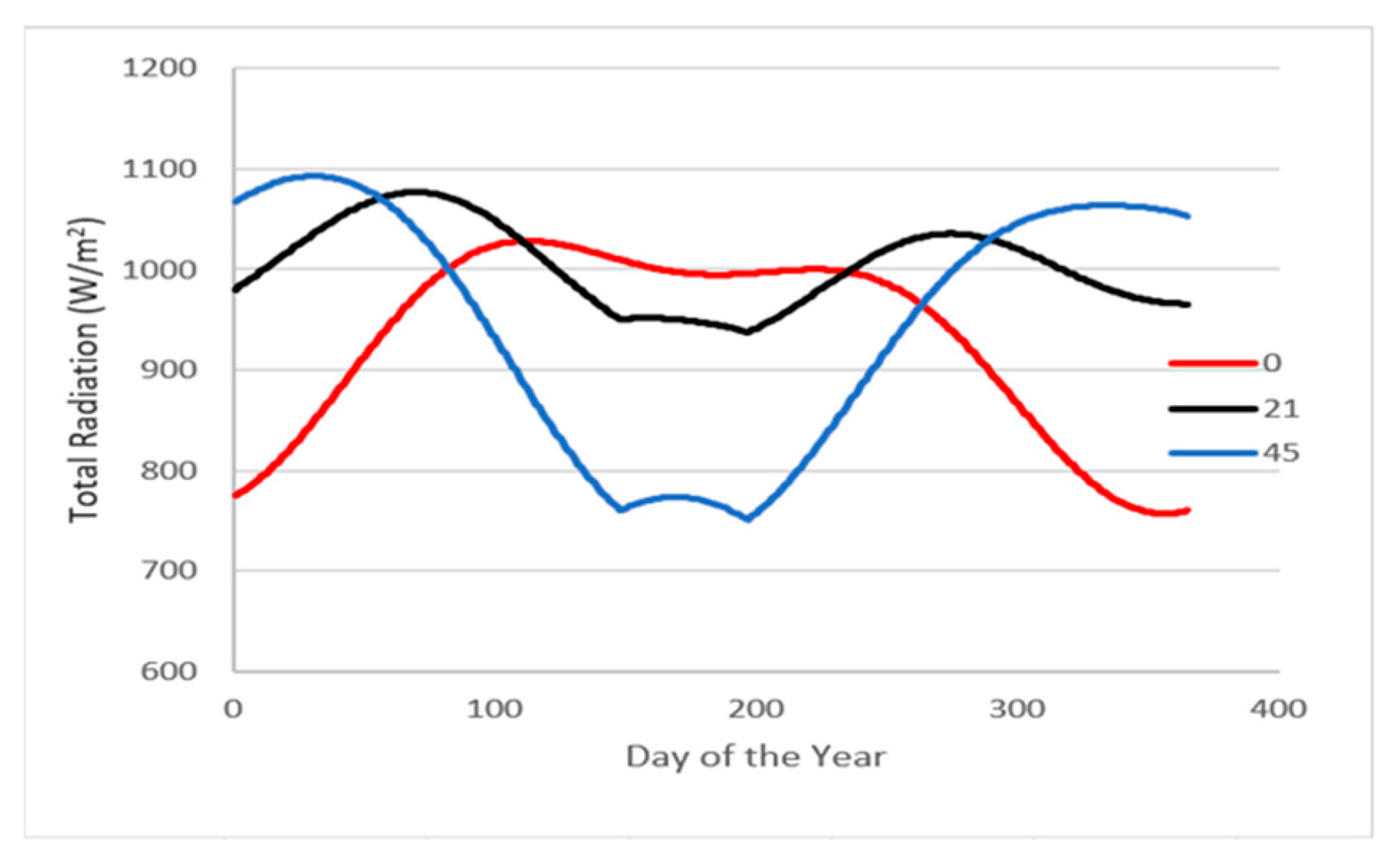
This section will give a detailed description of the methodology applied to evaluate the proposed systems. Mathematical modeling for the solar intensity, solar collectors, and the five ORC systems. We must understand the nature of solar radiation so that the engineering analysis of solar energy systems can be performed. The solar radiation calculation was carried out using two different procedures, a mathematical one and an experimental one using NASA data. Jeddah city has been chosen for calculation comparison between the developed mathematical modeling and the NASA data, where solar irradiance is projected into a specific square meter of every place on Earth. Data from the NASA website [
33] was acquired for radiation at Jeddah longitude and latitude at each hour from 2005 until 2020. It should be noted that all radiation travels at the speed of light, which is the product of the wavelength and the frequency of the radiation. Equation (1) shows the speed of light,
, in a medium (m/s):
where
is the wavelength (μm),
is the frequency (
),
is the speed of light in a vacuum (m/s), and
is the index of refraction of the medium. The monochromatic emissive power of a blackbody,
(W/
-μm), in terms of temperature and wavelength, was developed by an equation called Planck’s equation for blackbody radiation, shown in Equation (2):
where
is the temperature of the body (K),
and
are constants. The monochromatic emissive power of a blackbody and the total emissive power,
(W/
), are related by Equation (3), the emissive power of a gray body is:
where
is the emissivity that ranges between 0 <
<1,
is the Stefan–Boltzmann constant =
W/
-
. Next, equations of time and solar time must be calculated due to the variations in the orbital velocity of the Earth throughout the year. The equation of time (
) is given by Equation (4) and expressed in minutes:
where
B = (360/350)
(n − 1). The conversion from local standard time to solar time involves two steps: the equation for time is added to the local standard time, and then a longitude correction is applied. The apparent solar time (
) is related to the local standard time
by Equation (5) as follows:
where
is the longitude of the site, °E of Greenwich. A standard meridian is found every 15 degrees from 0° at Greenwich, U.K. An important factor in calculating the solar intensity is having a clear sky radiation model. Because of the slight elliptical shape of the Earth’s orbit, the extraterrestrial radiant flux,
, varies throughout the year. It can reach a maximum of 1412 W/
near the beginning of January, the time when the Earth is closest to the sun, and a minimum of 1322 W/
near the beginning of July, the time when the Earth is farthest from the sun [
34]. Extraterrestrial solar irradiance,
, can be approximated using Equation (6):
The information on the solar energy collected by the collection absorber plate is necessary for the prediction of collector performance. An isotropic model was developed by [
35] to provide the absorbed radiation,
S, on an hourly basis. By substituting the hourly direct and diffuse radiation values with the appropriate monthly average values,
and
,
with
, and various (
) values with monthly average values, (
). The monthly average absorbed solar radiation,
S, can be estimated as shown in Equation (7):
where
τα is the energy absorbed by the collector. It is very hard to avoid heat losses in all thermal systems to the environment, but most of the solar radiation that strikes a collector’s surface is absorbed, transferred to the transport fluid, and then carried away as usable energy. Equations (8) and (9) show the energy losses from the collector,
, and the useful energy collected from a solar collector,
, at a steady state as follows:
where
is the overall heat transfer coefficient based on the collector area,
is the collector area,
is the global solar irradiance at the collector plane,
is the mean temperature of the absorber plate,
is the ambient temperature,
is the fluid mass flow rate, and
and
are the fluid’s outlet and inlet temperatures. Finally, the collector efficiency,
, is determined using the gross collector aperture area,
, and can be expressed by Equation (10):
After discussing mathematical modeling for the solar intensity and evacuated tube collector, we must propose models for the proposed ORC systems.
Table 2 shows different mathematical equations for each system, including heat input, heat output, the turbines’ work, the pumps’ work, and the balance fraction.
Efficiency, power, and energy equations for all systems shown in Equations (11)–(13) are as follows:
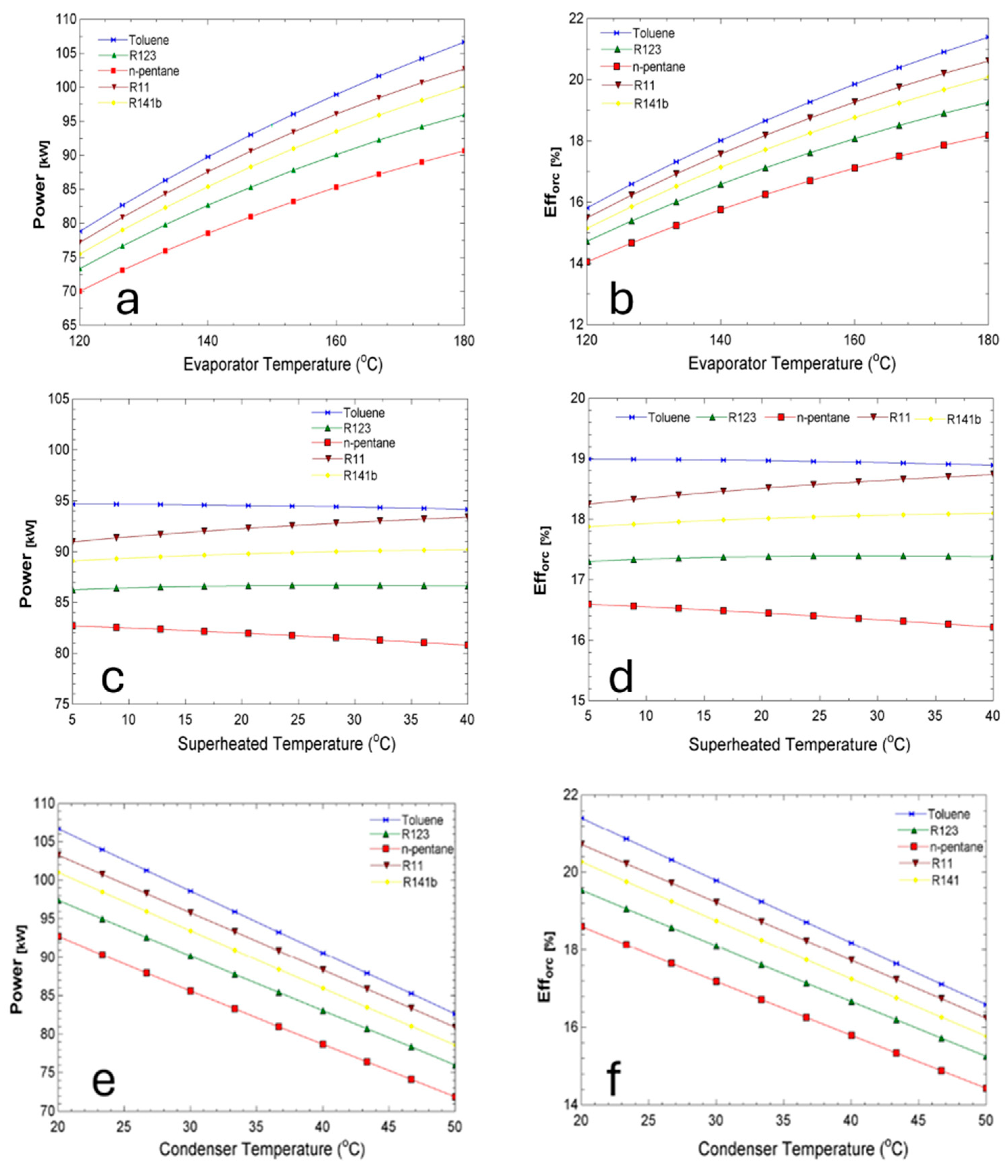
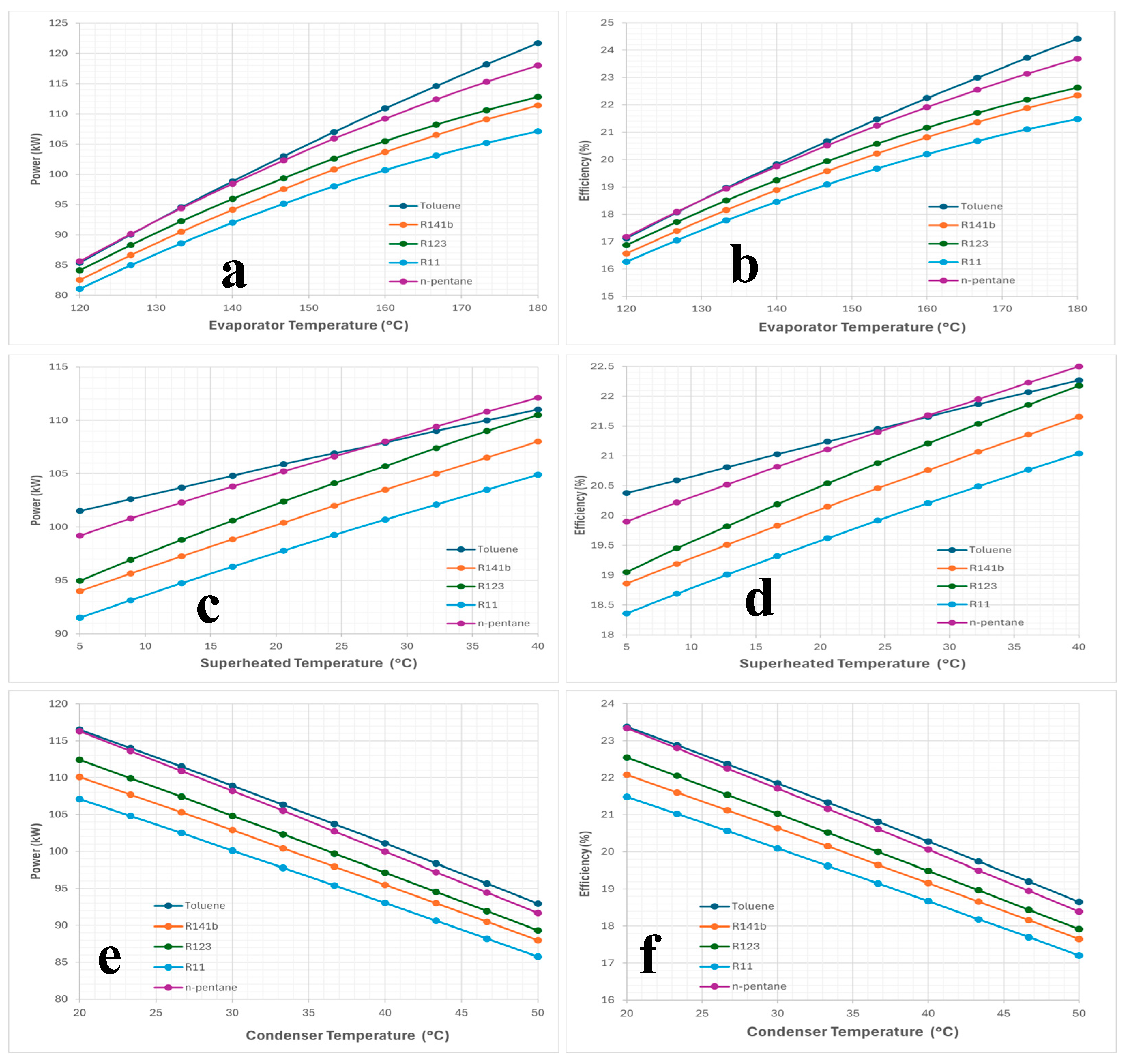
Finally, the investigation will study the parameters provided in
Table 3, such as the temperature of the evaporator, the temperature of the condenser, the difference in superheated temperature, and the pressure of regenerative and reheat. Those parameters are used to solve for the power and efficiency of each system for comparisons. The study assumes that the efficiency of turbines and pumps is 85%, the effectiveness of heat exchangers is 85%, and the efficiency of solar collectors is 62% [
36]. Also, the average solar intensity in Jeddah is assumed to be 0.8
[
33], daylight hours are 12 h [
33], and tariff cost is
$0.08/kWh [
37].
5. Conclusions
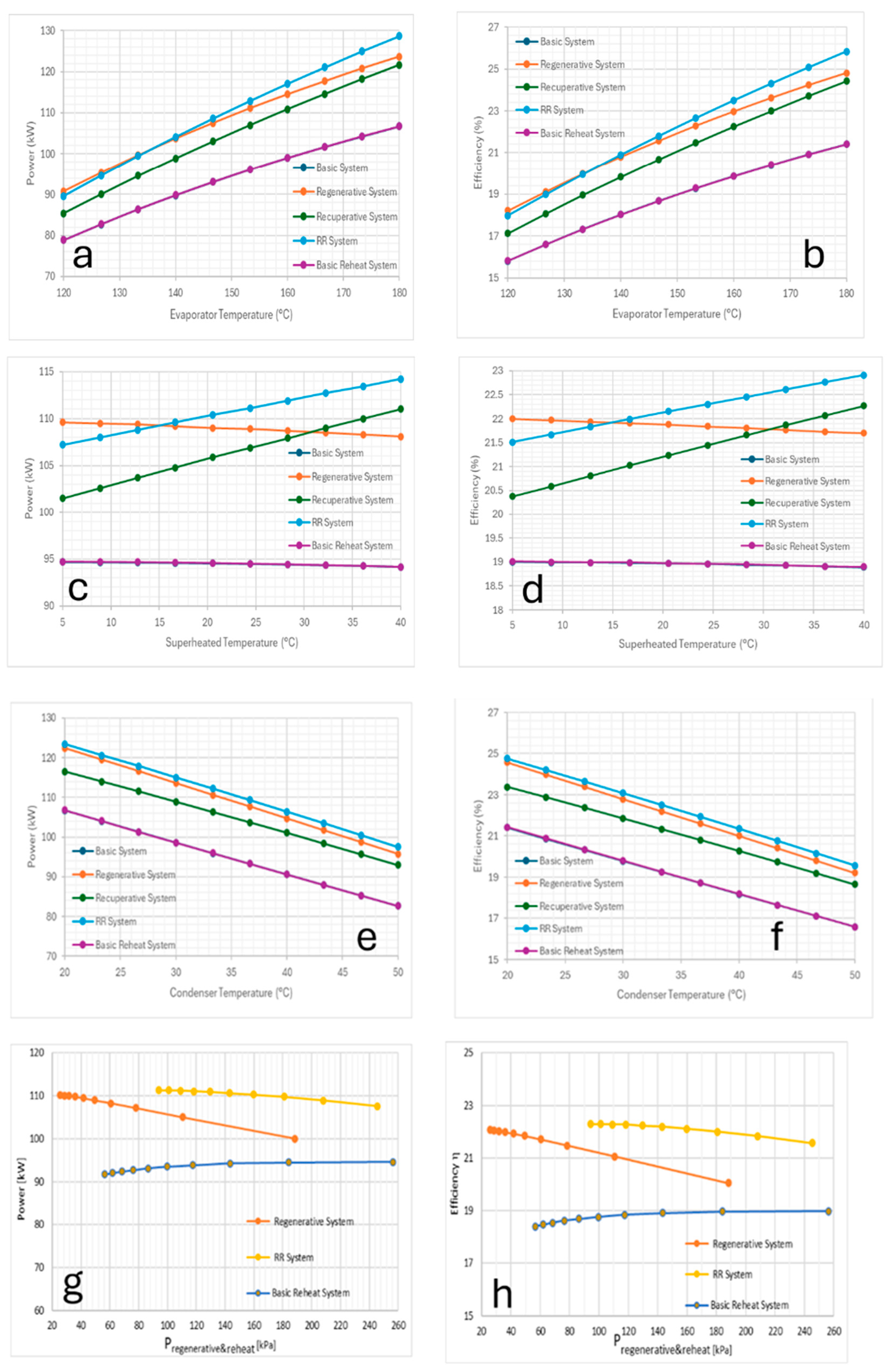
The purpose of this paper was to study the thermodynamic performance analysis and design of an organic Rankine cycle (ORC) driven by solar energy for power generation. This study considered five ORC systems: basic, basic with recuperative, basic with regenerative, basic with RR, and basic with reheat, simulated for five different working fluids: toluene, R123, R11, n-pentane, and R141b. The effects of changing different parameters, such as the temperature of the evaporator, temperature of the condenser, difference in superheated temperature, and pressure of regenerative and reheat were investigated. Simulations were obtained by using the Engineering Equation Solver (EES) software.
Optimum results were obtained for each system using toluene as a working fluid for the cycle. Input parameters were identified as 180 °C for the evaporator temperature, and 35 °C for the condenser temperature for all the systems. The difference in superheated temperature was 17.5 °C for all the systems except for the ORC basic with RR system which had an input value of 22.5 °C. These results will be reviewed in the following points:
The system with basic ORC without reheat cycle has an efficiency and power of 21.4%, 106.7 kW, respectively.
The system with recuperative ORC without reheat cycle has an efficiency and power of 24.42%, 121.7 kW, respectively.
The system with regenerative ORC without reheat cycle has an efficiency and power of 24.81%, 123.7 kW, respectively.
The system with RR-ORC without reheat cycle has an efficiency and power of 25.83%, 128.7 kW, respectively.
The system with basic ORC incorporating a reheat cycle has an efficiency and power of 21.41% and 106.71 kW, respectively.
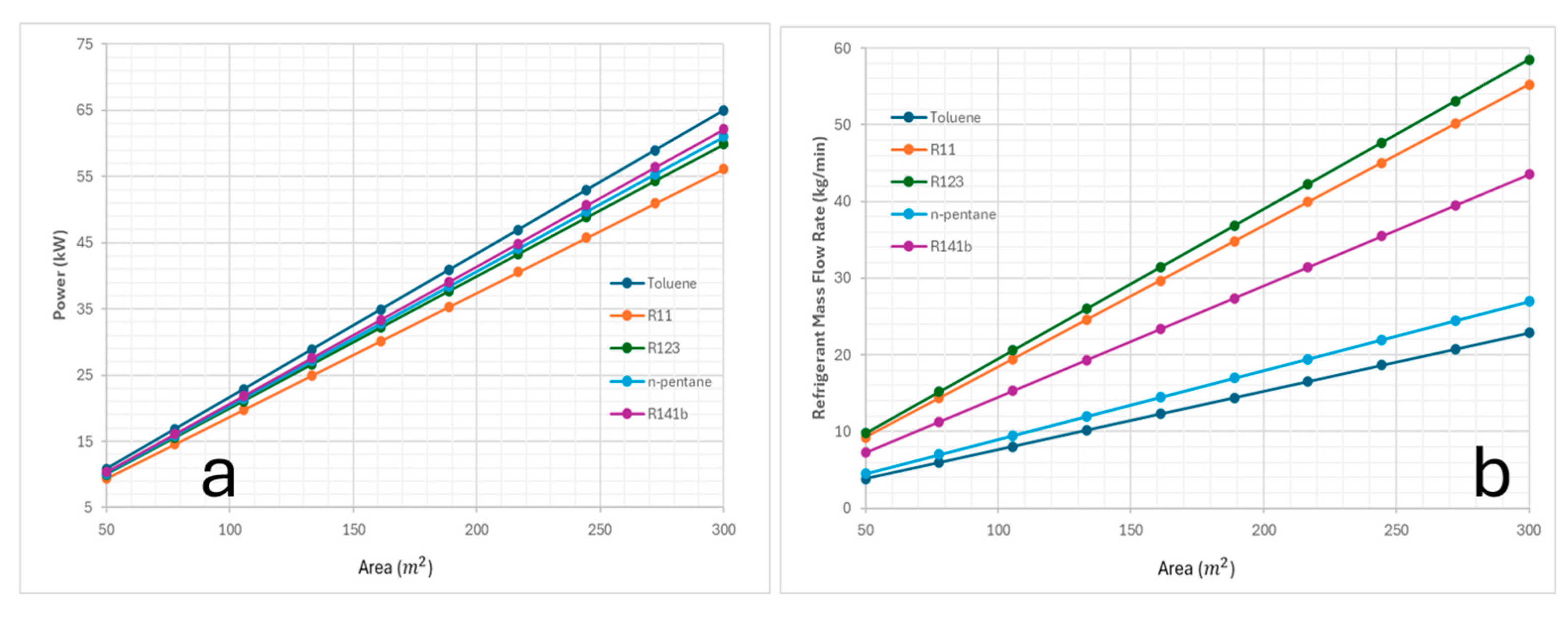
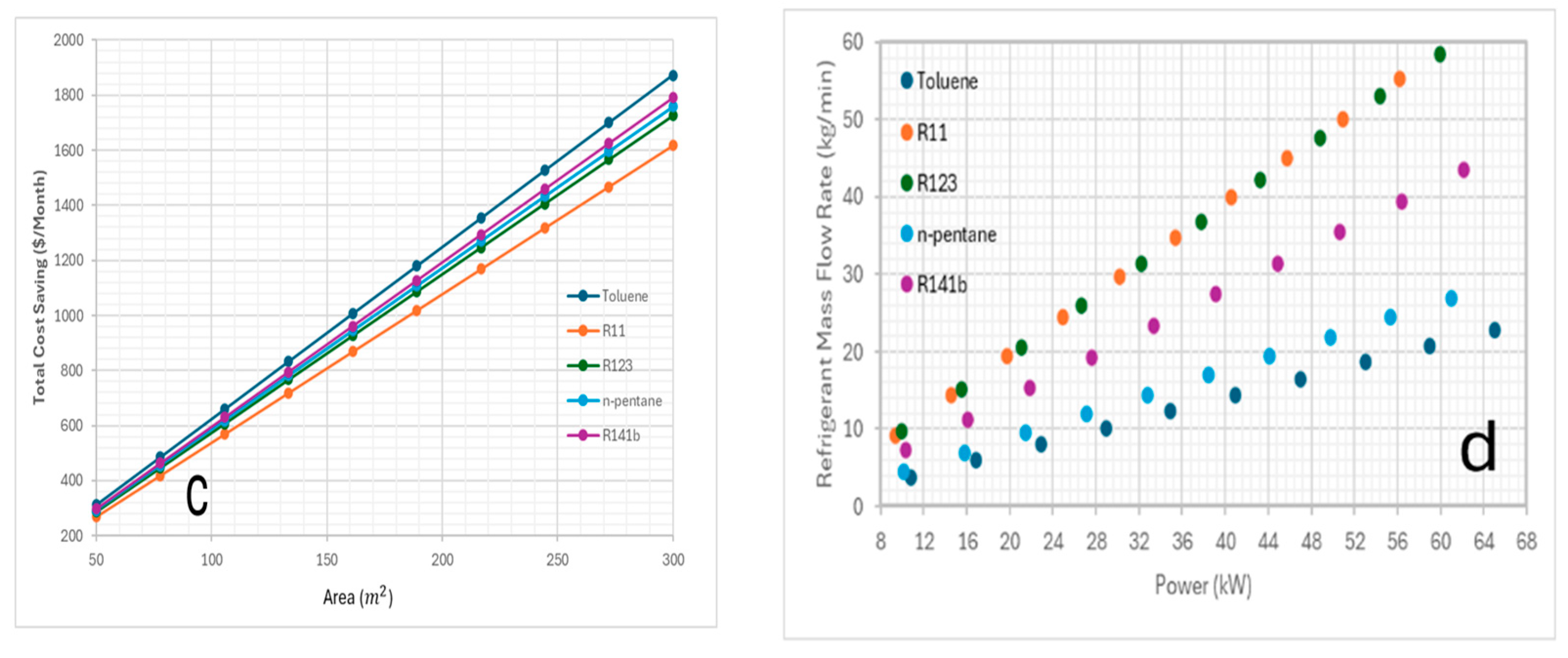
The solar collector area had an influence on power and cost savings where toluene showed an optimum savings of $1872/month at the largest area which supports the idea of investing in larger solar collector areas when feasible would be the best choice.
For future work, the current study proposes several research methods for advancing solar-ORC systems, including developing transient models, implementing machine learning to optimize performance trade-offs, and investigating hybrid configurations integrating thermal energy storage and PV-T systems. These future studies will use current insights and performance benchmarks to address dynamic operational requirements in practical solar-thermal power systems.


